


INSTALLATION TESTERS
C.A 6116N
C.A 6117
ENGLISH
User's manual
99 Washington Street
Melrose, MA 02176
Phone 781-665-1400
Toll Free 1-800-517-8431
Visit us at www.TestEquipmentDepot.com

Thank you for purchasing a C.A 6116N or C.A 6117 installation tester. To obtain the best service from your unit:
read this user manual carefully,
comply with the precautions for use.
WARNING, risk of DANGER! The operator must refer to these instructions whenever this danger symbol appears.
Useful information or tip. Current clamp.
USB socket. Auxiliary rod.
The voltage on the terminals must not exceed 550 V. Equipment protected by double insulation.
The product is declared recyclable following a life cycle analysis in accordance with standard ISO 14040.
The CE marking indicates conformity with European LVD and EMC directives.
Chauvin Arnoux has adopted an Eco-Design approach in order to design this appliance. Analysis of the complete
lifecycle has enabled us to control and optimize the effects of the product on the environment. In particular this appliance exceeds regulation requirements with respect to recycling and reuse.
The rubbish bin with a line through it means that in the European Union, the product must undergo selective disposal
in compliance with Directive WEEE 2002/96/EC.
Definition of measurement categories:
Measurement category IV corresponds to measurements taken at the source of low-voltage installations.
Example: power feeders, counters and protection devices.
Measurement category III corresponds to measurements on building installations.
Example: distribution panel, circuit-breakers, machines or fixed industrial devices.
Measurement category II corresponds to measurements taken on circuits directly connected to low-voltage installations.
Example: power supply to electro-domestic devices and portable tools.
PRECAUTIONS FOR USE
This device is protected against accidental voltages of not more than 600V with respect to earth in measurement category III or
300V with respect to earth in measurement category IV (under shelter). The protection provided by the device may be compromised if it is used other than as specified by the manufacturer.
Do not exceed the maximum rated voltage and current and the measurement category.
Never exceed the protection limits indicated in the specifications.
Comply with the conditions of use, namely the temperature, the humidity, the altitude, the degree of pollution, and the place
of use.
Do not use the device or its accessories if they seem damaged.
Do not use the device if the battery compartment cover is missing or incorrectly installed.
To recharge the battery, use only the mains adapter unit provided with the device.
To replace the battery, disconnect everything connected to the device and set the switch to OFF.
Do not use a battery with a damaged jacket.
Use connection accessories of which the overvoltage category and service voltage are greater than or equal to those of the
measuring device (600 V Cat. III or 300 V Cat. IV).
Troubleshooting and metrological checks must be done only by accredited skilled personnel.
Wear the appropriate protective gear.
2

CONTENTS
1. FIRST START-UP .............................................................. 4
1.1. Unpacking ..............................................................4
1.2. Charging the battery
1.3. Carrying the device
............................................... 5
................................................5
1.4. Use on a desktop ................................................... 6
1.5. Brightness of the display ........................................ 6
1.6. Choice of language
................................................7
2. PRESENTATION OF THE DEVICES ................................8
2.1. Functions of the devices
.......................................9
2.2. Keypad ...................................................................9
2.3. Display unit ........................................................... 10
2.4. USB port
...............................................................10
3. USE ................................................................................. 11
3.1. General
................................................................. 11
3.2. Voltage measurement ...........................................11
3.3. Resistance and continuity measurement .............13
3.4. Insulation resistance measurement
...................... 17
3.5. 3P earth resistance measurement ........................ 20
3.6. Loop impedance measurement (Z
3.7. Earth measurement on live circuit (Za, Ra) ............27
) ..................... 24
S
3.8. Selective earth measurement on live circuit ......... 32
3.9. Measurement of the line impedance (Z
3.10. Measurement of the voltage drop in the
cables (
DV) .......................................................... 38
)...............35
i
3.11. Test of residual current device ............................41
3.12. Current and leakage current measurement ........49
3.13. Direction of phase rotation ................................. 51
3.14. Power measurement ..........................................53
3.15. Harmonics .......................................................... 56
3.16. Compensation for the resistance of the
measurement leads ............................................ 59
3.17. Adjustment of the alarm threshold ..................... 61
4. ERROR INDICATION ...................................................... 62
4.1. No connection ...................................................... 63
4.2. Out of measurement range ...................................63
4.3. Presence of dangerous voltage ............................ 63
4.4. Invalid measurement ............................................63
4.5. Device too hot ...................................................... 63
4.6. Check of internal protection devices ....................64
5. SET-UP ............................................................................ 65
6. MEMORY FUNCTION ....................................................68
6.1. Organization of the memory and navigation ........68
6.2. Entering the storage function ............................... 68
6.3. Create a tree ......................................................... 69
6.4. Record the measurement ..................................... 70
6.5. Read the records .................................................. 71
6.6. Erasure .................................................................73
6.7. Errors
7. DATA EXPORT SOFTWARE
.................................................................... 73
..........................................74
8. TECHNICAL CHARACTERISTICS ................................75
8.1. General reference conditions ...............................75
8.2. Electrical characteristics.......................................75
8.3. Variations in the range of use
8.4. Intrinsic uncertainty and operating uncertainty
............................... 86
.... 89
8.5. Power supply ........................................................89
8.6. Environmental conditions ..................................... 91
8.7. Mechanical characteristics .................................. 91
8.8. Conformity to international standards
8.9. Electromagnetic compatibility (EMC)
.................. 91
...................91
9. DEFINITIONS OF SYMBOLS ......................................... 92
10. MAINTENANCE ............................................................ 94
10.1. Cleaning .............................................................94
10.2. Replacing the battery
10.3. Resetting the device
......................................... 94
........................................... 95
10.4. Metrological check ............................................. 95
10.5. Repair ................................................................. 95
10.6. Updating of the internal software
....................... 95
11. WARRANTY ................................................................. 96
12. TO ORDER
....................................................................97
12.1. Accessories ........................................................ 97
12.2. Replacement parts ............................................. 97
13. APPENDIX
.................................................................... 99
13.1. Table of fuses managed by the C.A 6117 ..........99
3

1.1. UNPACKING
1. FIRST START-UP
➀
➂
➈
➃
➁
One C.A 6116N or C.A 6117.
1
One mains charger with cable for the battery.
2
Data export software on CD-ROM and a USB A/B cord.
3
➆
➅
➇
14
➄
12
➉
11
13
One tripod cable with mains plug (adapted to the country of sale.
4
One tripod cable, 3 safety leads.
5
Three probe tips (red, blue, and green).
6
Three crocodile clips (red, blue, and green).
7
Two elbowed-straight safety leads (red and black).
8
One 4-point hands-free strap.
9
One hand strap.
10
One remote probe.
11
One carrying bag.
12
One user manuals on CD-ROM (1 file per language).
13
One multilingual safety sheet.
14
4

50 / 60 Hz
1.2. CHARGING THE BATTERY
Before the first use, start by fully charging the battery. The charging must be done between 0 and 45°C.
> 90 VAC
< 264 VAC
Battery
loading...
Remove the cover from the mains connector on
the device.
Loading
The indicator of the
device lights.
completed.
Charging time:
approximately 5h.
Set the switch to OFF, but charging is possible when the device is not off.
1.3. CARRYING THE DEVICE
The 4-point hands-free strap will let you use the device while leaving your
hands free. Snap the four fasteners of the strap onto the four lugs on the
device.
Pass the strap around your neck.
Adjust the length of the strap, then the tilt of the device.
The indicator goes
off.
5
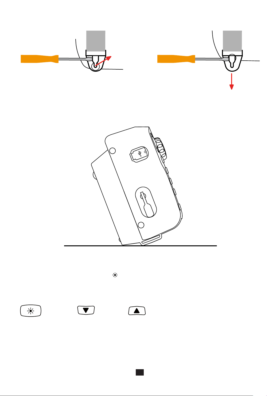
To withdraw the strap, slide a flat screwdriver under the tab of the fastener to lift it, then slide the fastener down.
1.4. USE ON A DESKTOP
For use on a desktop, have the device rest on the fasteners of the hand strap and on the housing.
This lets the display unit be read directly.
1.5. BRIGHTNESS OF THE DISPLAY
To adjust the brightness of the display, press the key and one of the arrow keys simultaneously.
+
sustained
press
or
6

1.6. CHOICE OF LANGUAGE
Before using the device, first choose the language in which you want the device to display messages.
Set the switch to SET-UP.
SET UP
11-21-2013 11:17
Use the directional keypad to select the languages icon:
OK
OFF
OK
Press the OK key to validate your
choice.
SET-UP
Select your language, from among those proposed, using the keys and validate by pressing the OK key again.
You can download other languages from our site’s support space (see §10.6).
7

2. PRESENTATION OF THE DEVICES
TEST
TEST button to start
the measurements.
Four function
keys.
Connection terminals.
/
OK
Switch for selection
of the measurement
function or SETUP.
SET UP
OFF
Indicator light.
Stud for fixing on the
4-point hands-free
strap.
USB port for data
transfer to a PC.
Help key.
Brightness adjustment key.
Battery charging
connector.
Directional keypad:
four navigation keys
and one validation
key.
Fasteners for the hand
strap, also used to tilt
the device.
8

2.1. FUNCTIONS OF THE DEVICES
C.A 6116N and C.A 6117 installation testers are portable measuring devices with a colour graphic display. They are powered by
a rechargeable battery with a built-in charger and external power supply unit.
These instruments are intended to check the safety of electrical installations. It can be used to test a new installation before it is
powered up, to check an existing installation, whether in operation or not, or to diagnose a malfunction in an installation.
Measurement
functions
Controls one thirteen-position switch, one five-key navigator, one keypad with four function keys, one context-
voltage measurement
continuity and resistance measurement
insulation resistance measurement
earth resistance measurement (with 3 rods)
loop impedance measurement (Zs)
earth resistance on live circuit measurement (with an auxiliary probe)
selective earth resistance measurement (with an auxiliary probe and an optional current clamp)
calculation of the short-circuit current and of the fault voltages
line impedance measurement (Zi)
measurement of the voltage drop in the cables (for the C.A 6117 only)
test of type AC, A, and B residual current devices, in ramp mode, in pulse mode, or in non-tripping
mode (type B with the C.A 6117 only)
current measurement (with an optional current clamp)
detection of direction of phase rotation
active power and power factor measurement (single-phase or balanced three-phase network) with
display of the voltage and/or current curves
voltage and current harmonic analysis (with an optional clamp)
sensitive help key, one brightness key, and one TEST button.
Display 5.7” (115 x 86mm) colour graphic display unit, 1/4 VGA (320 x 240 points).
The only difference between the C.A 6116N and the C.A 6117 is that the C.A 6117 can test type B RCDs.
2.2. KEYPAD
The actions of the 4 function keys are indicated on the display unit by adjacent icons. They depend on the context.
The help key can be used in all functions. The help function is context-sensitive: it depends on the function.
The key is used to adjust the brightness of the display.
The directional keypad comprises four navigation keys and one validation key.
9

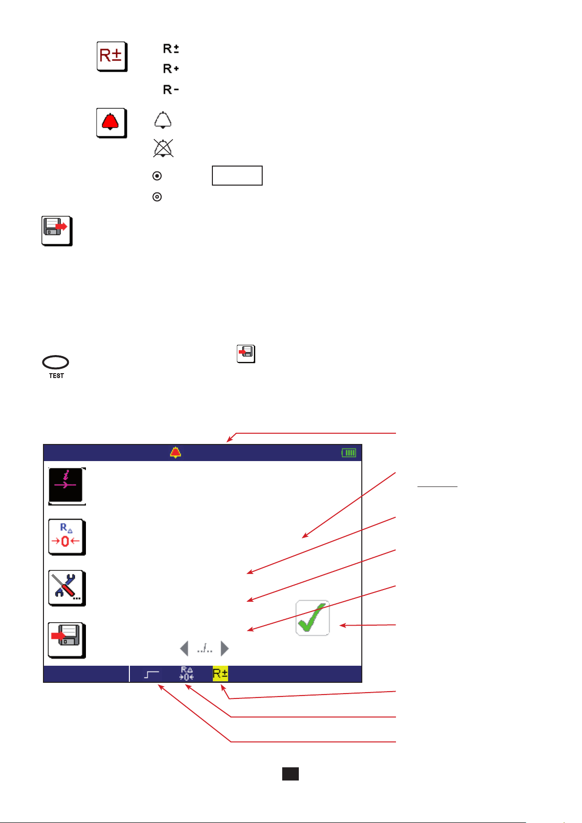
2.3. DISPLAY UNIT
➀
➅
➈
➁
11-21-2013 10:47
6 mA
L-PE 230.3 V
L-N
N-PE
6 %
LOOP ZS
➂
50 . 0 Ω 50 . 1 Hz
230.4 V
0.8 V
➃
➄
L
➆
➇
➉
Top strip
1
Date and time
2
Alarm threshold
3
Frequency measured
4
Condition of the battery
5
Icons representing the functions of the keys
6
7
8
9
10
11
11
Position of the phase on the socket outlet
Display of measurement results
Bottom strip
Name of function
Information about the measurement in progress
2.4. USB PORT
The USB port of the device is used to transfer the stored data to a PC (see §7). This operation requires the prior installation of a
specific peripheral driver and other software.
The USB port can also be used to update the device’s internal software (see §10.6).
The USB cord and the associated software are supplied with the device.
10

3. USE
3.1. GENERAL
When it leaves the plant, the device is configured so that it can be used without changing the parameters. For most measurements, simply select the measurement function by turning the switch and press the TEST button.
However, you can also parameterize:
the measurements, using the function keys,
or the device itself, using SET-UP.
The device is not designed to operate when the charger is connected. The measurements must be made using battery
power.
3.1.1. CONFIGURATION
When configuring the measurements, you can always choose between:
validating by pressing the OK key,
or exiting without saving by pressing the key.
3.1.2. HELP
In addition to an intuitive interface, the instrument provides complete help in use and analyses and appraisals. Three types of
help function are available:
Help before the measurement can be accessed using the key. It indicates the connections to be made for each function
and important recommendations.
Error messages appear, as soon as the TEST button is pressed, to report connection errors, measurement parameterizing
errors, out-of-range values, defective installations tested, etc.
Help associated with the error messages. Messages containing the icon invite you to look up the help for ways to
eliminate the error found.
3.1.3. REFERENCE POTENTIAL
The user is assumed to be at the reference earth potential. He/she must therefore not be insulated from earth: must not
wear insulating shoes or insulating gloves and must not use a plastic object to press the TEST button.
3.2. VOLTAGE MEASUREMENT
Whichever function is chosen, except for SET-UP, the device always starts by measuring the voltage present on its terminals.
3.2.1. DESCRIPTION OF THE MEASUREMENT PRINCIPLE
The device separates the alternating voltage from the direct voltage and compares the amplitudes to decide whether the signal
is AC or DC. In the case of an AC signal, the frequency is measured and the device calculates the RMS value of the AC part and
displays it. In the case of a DC signal, the device does not measure its frequency, but calculates its mean value and displays it.
For measurements made at the mains voltage, the device checks that the connection is correct and displays the position of the
phase on the socket outlet. It also checks the presence of a protective conductor on the PE terminal by means of the contact the
user makes with his/her finger by touching the TEST button.
11

3.2.2. MAKING A MEASUREMENT
Connect the lead to the device to be tested. As soon as the device is powered up, it measures the voltages present on its terminals
and displays them, whatever the setting of the switch.
/
In the ZS (RA/SEL.) and RCD, settings, the device also indicates the position of the phase on the display unit using the symbol.
The mains socket outlet of the measuring cable is marked with a white reference spot.
: the phase is on the right-hand contact of the mains plug when the white spot is up.
: the phase is on the left-hand contact of the mains plug when the white spot is up.
: the device cannot determine where the position of the phase, probably because the PE is not connected or the L and
PE conductors are interchanged.
The L symbol is displayed as soon as the voltage is high enough (> UL programmable in SET-UP). The terminal identified
as L is the one that has the highest voltage with respect to PE.
3.2.3. ERROR INDICATION
The only errors reported in voltage measurement are values outside the voltage measurement range. These errors are reported
in clear language on screen.
12

3.3. RESISTANCE AND CONTINUITY MEASUREMENT
3.3.1. DESCRIPTION OF THE MEASUREMENT PRINCIPLE
For continuity measurements, the device generates a DC current of 200 or 12 mA, at the user’s discretion, between the W and
COM terminals. It then measures the voltage present between these two terminals and from it deduces the value of R = V/I.
For resistance measurements (current chosen = kW), the device generates a DC voltage between the W and COM terminals. It
then measures the current between these two terminals and from it deduces the value of R = V/I.
In the case of a measurement at high current (200 mA), at the end of one second, the device reverses the direction of the current
and makes another measurement for one second. The result displayed is the mean of these two measurements. It is possible to
make measurements with either the positive or the negative polarity of the current disabled.
For measurements at low current (12 mA or kW), the polarity is positive only.
3.3.2. MAKING A MEASUREMENT
To comply with standard IEC-61557, the measurements must be made at 200 mA. The reversal of the current serves to compensate for any residual electromotive forces and, more important, to check that the continuity is in fact duplex.
When you make continuity measurements that are not contractual, prefer a current of 12 mA. Even though the results cannot be
regarded as those of a normative test, this significantly increases the life of the device between charges and forestalls untimely
tripping of the installations if there is a connection error.
The permanent mode is used to chain measurements without having to press the TEST button each time.
If the object to be measured is inductive, it is better to switch to pulse mode at 200 mA and make a measurement at positive
polarity, then a measurement at negative polarity, manually, in order to leave time for the measurement to settle.
The alarm, if activated, serves to inform the user, by an audible signal, that the measurement is below threshold, making it unnecessary to look at the display unit to check this point.
Set the switch to W .
Use the leads to connect the device to be tested between the W and COM terminals of the device. The object to be tested must not be live.
SET UP
R
/
OFF
3.3.3. CONFIGURING THE MEASUREMENT
Before starting the measurement, you can configure it by modifying the parameters displayed:
Choice of measurement current: kW, 12 mA or 200 mA.
200mA
The high current (200 mA) can be used only to measure low resistances, up to 40 W.
The low current (12 mA) is used to make measurements up to 400 W.
The choice kW is used to make resistance measurements up to 400 kW.
To correct for the resistance of the measurement leads (leads and probe tips or crocodile clips), for measurements
at 12 and 200 mA (see §3.16).
Pressing the TEST button starts only one measurement (pulse mode).
Pressing the TEST button starts the continuous measurement (permanent mode). To
stop it, you must press the TEST button again.
13
Automatic reversal of polarity for a measurement at 200 mA.
TEST
k Ω
Ω
Measurement at positive polarity only.
Measurement at negative polarity only.
To activate the alarm.
To deactivate the alarm.
002.00
Before the measurement: to display the measurements already recorded.
6 %
Once the parameters have been defined, you can start the measurement.
3.3.4. READING OF THE RESULT
In the case of a 200 mA current:
11-22-2013 10:47
After the measurement: to record it.
The direction of the arrow indicates whether you can make a reading (arrow pointing out) or a recording (arrow
pointing in).
The percentage indicates the quantity of memory already used.
If you selected the pulse mode, press the TEST button once and the measurement stops automatically when it is over.
If you selected the permanent mode, press the TEST button once to start the measurement and a second time to
stop it, or else press the record key
2.00 Ω - - .- Hz
6 %
directly.
To set the alarm threshold (see §3.17). The default threshold is 2W.
Value of the alarm threshold.
200 mA
1 %
CONTINUITY
0 . 8 3 Ω
I 2 0 7 . 4 m A
R + 0 . 5 9 Ω
R - 1 . 0 8 Ω
Measurement result:
(R+) + (R-)
R =
2
Measurement current.
Measurement with a positive current (R+).
Measurement with a negative current (R-).
Case where the measurement is
below the alarm threshold.
Measurement with reversal of polarity.
Compensation for the resistance of
the measurement leads is activated.
Permanent mode.
14

To see the next display page.
22/07/2014 10:47
200 mA
2.00 Ω - - .- Hz
U Ω 0 . 0 V
L - PE 0 . 00 V
L - N X V
N - PE
1 %
CIAGLOSC
In the case of a 12 mA current, there is no current reversal.
X V
External voltage present on the
terminals just before the start of the
measurement.
11-22-2013 10:47
12 mA
I 1 2 . 3 m A
1 %
CONTINUITY
2.00 Ω - - .- Hz
1 8 . 4 Ω
Value of the alarm threshold.
Measurement result.
Current measurement.
Case where the measurement is
above the alarm threshold.
The polarity of the current is positive.
Compensation for the resistance of
the measurement leads is activated.
Pulse mode.
15

In the case of a resistance measurement (kW), there is no current reversal and no compensation for the measurement leads.
11-22-2013 10:47
kΩ
1 %
RESISTANCE
- - .- Hz
1 . 5 8 k Ω
Measurement result.
Case where the measurement is
below the alarm threshold.
Permanent mode.
3.3.5. ERROR INDICATION
The commonest error in the case of a continuity or resistance measurement is the presence of a voltage on the terminals. An error
message is displayed if a voltage greater than 0.5 VRMS is detected and you press the TEST button.
In this case, the measurement is not enabled. Eliminate the cause of the interference voltage and start the measurement over.
Another possible error is measurement of an overly inductive load that prevents the measurement current from stabilizing. In this
case, start the measurement in permanent mode with only one polarity and wait for the measurement to stabilize.
For help with connections or any other information, use the help function.
16

3.4. INSULATION RESISTANCE MEASUREMENT
3.4.1. DESCRIPTION OF THE MEASUREMENT PRINCIPLE
The device generates a DC test voltage between the COM and MW terminals. The value of this voltage depends on the resistance
to be measured: it is greater than or equal to UN when R ≥ RN = UN /1 mA, and less otherwise. The device measures the voltage
and current present between the two terminals and from them deduces the value of R = V / I.
The COM terminal is the voltage reference point. The MW terminal therefore provides a negative voltage.
3.4.2. MAKING A MEASUREMENT
The alarm, if activated, serves to inform the user, by an audible signal, that the measurement is below threshold, making it unnecessary to look at the display unit to check this point.
Set the switch to MW.
Use the leads to connect the device to be tested between the COM and MW
terminals of the device. The object to be tested must not be live.
SET UP
OFF
R
To avoid leakage during the insulation measurement, which would
throw off the measurement, do not use the measuring cable when
/
you make this type of measurement, but two simple leads.
Generally, an insulation measurement on an installation is made between the interconnected phase(s) and neutral, on the one
hand, and earth, on the other.
L1
L2
L3
N
PE
/
If the insulation is not sufficient, you must then make the measurement between each of the pairs to locate the fault. It is for this
reason possible to index the recorded value with one of the following values:
L-N, L-PE, N-PE, L1-PE, L2-PE, L3-PE, L1-N, L2-N, L3-N, L1-L2, L2-L3 or L1-L3
The remoted TEST button of the optional remote control probe makes it easier to trigger the measurement. To use the remote
control probe, refer to its user’s manual.
C.A 6113/16/17
with
Operation only
L1
L2
L3
PE
17

TEST
M Ω
Ω
3.4.3. CONFIGURING THE MEASUREMENT
Before starting the measurement, you can configure it by modifying the parameters displayed:
To choose the nominal test voltage UN: 50, 100, 250, 500 or 1000 V.
To activate the alarm.
To deactivate the alarm.
k
Before the measurement: to display the measurements already recorded.
6 %
3.4.4. READING OF THE RESULT
11-22-2013 10:47
During or after the measurement: to record it.
The direction of the arrow indicates whether you can make a reading (arrow pointing out) or a recording (arrow
pointing in).
The percentage indicates the quantity of memory already used.
Once the parameters have been defined, you can start the measurement.
Keep the TEST button pressed until the measurement is stable. The measurement stops when the TEST button
is released.
Before disconnecting the leads or starting another measurement, wait a few seconds for the UN voltage to be zéro.
0500.0
500 kΩ - - .- Hz
To set the alarm threshold (see §3.17). As default, the threshold is set to
R (kW) = UN / 1 mA.
Value of the alarm threshold.
2 %
INSULATION
3 1 . 0 6 M Ω
V
577
7 s
Press TEST until the measurement
is stable
The bargraph provides a rapid quantitative indication of the insulation.
Measurement result.
The test voltage UN is present and
dangerous.
Duration of the measurement.
Case where the measurement is
above the alarm threshold.
To change display pages.
18

To see the next display page.
11-22-2013 10:47
500 kΩ - - .- Hz
U M Ω 0 . 3 V
External voltage present on the
L - PE X V
L - N X V
N - PE
Press TEST until the measurement
2 %
INSULATION
3.4.5. ERROR INDICATION
The commonest error in the case of an insulation measurement is the presence of a voltage on the terminals. If it is greater than
10 V (the exact value depends on UN, see § 8.2.5), the insulation measurement is not enabled. Eliminate the voltage and start the
measurement over.
is stable
X V
terminals just before the start of the
measurement.
To change display pages.
The measurement may be unstable, probably because of an overly capacitive load or an insulation fault. In this case, read the
measurement on the bargraph.
For help with connections or any other information, use the help function.
19

3.5. 3P EARTH RESISTANCE MEASUREMENT
This function is the only one that can measure an earth resistance when the electrical installation to be tested is not live (new installation, for example). It uses two auxiliary rods, with the third rod being constituted by the earth electrode to be tested (whence
the name “3P”).
It can be used on an existing electrical installation, but the power must be cut off (main RCD). In all cases (new or existing installation), the earthing strip of the installation must be open during the measurement.
It is possible to make a rapid measurement and measure only RE or else to make a more detailed measurement by also measuring the resistances of the rods.
3.5.1. DESCRIPTION OF THE MEASUREMENT PRINCIPLE
The device generates between the H and E terminals a square wave at a frequency of 128 Hz and an amplitude of 35 V. It measures the resulting current, IHE , along with the voltage present between the S and E terminals, USE. It then calculates the value of
RE = USE/IHE.
To measure the resistances of the RS and RH rods, the device internally reverses the E and S terminals and makes a measurement.
It then does likewise with the E and H terminals.
3.5.2. MAKING A MEASUREMENT
There are several measurement methods. We recommend the «62%» method.
Set the switch to RE 3P.
Plant the H and S rods in line with the earth electrode. The distance between the S rod
and the earth electrode must be approximately 62% of the distance between the H rod
and the earth electrode.
In order to avoid electromagnetic interference, we recommend paying out the full length of
SET UP
the cables, placing them as far apart as possible, and not making loops.
earth
strap
/
OFF
H
S
62% d
d
Connect the cables to the H and S terminals. Power down the installation and disconnect the earth strap. Then connect the E
terminal to the earth electrode to be checked.
The alarm, if activated, serves to inform the user, by an audible signal, that the measurement is above threshold, making it unnecessary to look at the display unit to check this point.
3.5.3. CONFIGURING THE MEASUREMENT
Before starting the measurement, you can configure it by modifying the parameters displayed:
Choice of type of measurement: rapid, to measure RE only (icon crossed out), or detailed, to measure also rod
resistances RS and RH. This last case is useful if the ground is dry, making the resistance of the rods high.
To compensate for the resistance of the lead connected to the E terminal, for measurements of low values (see §3.16).
20

k Ω
Ω
To activate the alarm.
TEST
To deactivate the alarm.
050.00
Before the measurement: to display the measurements already recorded.
6 %
During or after the measurement: to record it.
The direction of the arrow indicates whether you can make a reading (arrow pointing out) or a recording (arrow
pointing in).
The percentage indicates the quantity of memory already used.
If the measurement must be made in a damp environment, remember to change the value of maximum contact voltage
UL in SET-UP (see §5) and set it to 25 V.
Press the TEST button to start the measurement. The measurement stops automatically.
This symbol invites you to wait while the measurement is in progress.
Do not forget to reconnect the earth strap at the end of the measurement before powering the installation back up.
To set the alarm threshold (see §3.17). As default, the threshold is set to 50W.
3.5.4. READING OF THE RESULT
In the case of a detailed measurement:
11-22-2013 10:47
R E 3 2 . 0 8 Ω
R s 1 . 5 8 k Ω
R h 1 . 3 2 k Ω
3 %
EARTH 3P
50.0 kΩ - - .- Hz
Value of the alarm threshold.
Measurement result.
Resistance of the S rod.
Resistance of the H rod.
Case where the measurement is
below the alarm threshold.
To see the voltages before the beginning of the test.
Compensation for the resistance of
the measurement leads is activated.
21

H
d
S
3.5.5. VALIDATION OF THE MEASUREMENT
To validate your measurement, move the S rod towards the H rod by 10% of d and make another measurement. Then move the
S rod, again by 10% of d, but towards the earth electrode.
H
S
52% d
62% d
72% d
/
d
The 3 measurement results must be the same to within a few percent. If this is the case, the measurement is valid. If not, it is
because the S rod is in the zone of influence of the earth electrode.
If the resistivity of the ground is homogeneous, it is necessary to increase distance d and repeat the measurements. If the resistivity of the ground is inhomogeneous, the measurement point must be moved either towards the H rod or towards the earth
terminal until the measurement is valid.
3.5.6. POSITIONING OF THE AUXILIARY RODS
To make sure that your earth measurements are not distorted by interference, we recommend repeating the measurement with
the auxiliary rods placed at a different distance and in another direction (for example rotated 90° from the first alignment).
2
S
H
S
E
d1
If you find the same values, your measurement is reliable. If the measured values are substantially different, it is probable that
they were influenced by earth currents or a groundwater artery. It may be useful to drive the rods deeper.
If the in-line configuration is not possible, you can plant the rods in a triangle. To validate the measurement, move the S rod on
either side of the line HE.
S
H
E
Avoid routing the connecting cables of the earth rods near or parallel to other cables (transmission or power supply), metal pipes,
rails, or fences, this in order to avoid the risk of cross-talk with the measurement current.
22

3.5.7. ERROR INDICATION
The commonest errors in the case of an earth measurement are the presence of an interference voltage or rod resistances that
are too high.
If the device detects:
a rod resistance greater than 15 kW,
a voltage greater than 25 V on H or on S when the TEST button is pressed.
In these two cases, the earth measurement is not enabled. Move the rods and start the measurement over.
To reduce the resistance of the rods RH (RS), you can add one or more rods, two metres apart, in the H (S) branch of the circuit.
You can also drive them deeper and pack the earth around them, or wet it with a little water.
For help with connections or any other information, use the help function.
23

3.6. LOOP IMPEDANCE MEASUREMENT (ZS)
R
R
In a TN or TT type installation, the loop impedance measurement is used to calculate the short-circuit current and to size the
protections of the installation (fuses or RCDs), especially their breaking capacity.
In a TT type installation, the loop impedance measurement makes it easy to determine the earth resistance without planting any
rods and without cutting off power to the installation. The result obtained, ZS, is the loop impedance of the installation between
the L and PE conductors. It is barely greater than the earth resistance.
From this value and the conventional touch voltage limit (UL), it is then possible to choose the rated differential operating current
of the RCD: IDN < UL / ZS.
This measurement cannot be made in an IT type installation because of the high earthing impedance of the supply transformer,
which may even be completely isolated from earth.
3.6.1. DESCRIPTION OF THE MEASUREMENT PRINCIPLE
The device starts by generating pulses having a duration of 1.1 ms and an amplitude of at most 7 A between the L and N terminals. This first measurement is used to determine ZL.
It then applies a low current, 6, 9 or 12 mA at the user’s discretion, between the L and PE terminals. This low current serves to
avoid tripping residual current devices of which the nominal current is greater than or equal to 30 mA. This second measurement
is used to determine ZPE.
The device then calculates loop resistance ZS = Z
= ZL+ZPE , and short-circuit current Ik = U
L-PE
LPE/ZS
.
The value of Ik serves to check the proper sizing of the protections of the installation (fuses or RCDs).
For greater accuracy, it is possible to measure ZS with a high current (TRIP mode), but this measurement may trip the RCD of
the installation.
3.6.2. MAKING A MEASUREMENT
Set the switch to ZS (RA/SEL.).
Connect the measuring cable to the device, then to the socket outlet of the installation to be tested.
SET UP
At the time of connection, the device first checks that the voltages present
on its terminals are correct, then determines the position of the phase (L) and
of the neutral (N) with respect to the protective conductor (PE) and displays
it. If necessary, it then automatically switches the L and N terminals so that
the loop measurement can be made without modifying the connections of
the device.
OFF
If possible, first disconnect all loads from the network on which you make the loop
measurement.
It is possible to eliminate this step if you use a measurement current of 6 mA, which
allows a leakage current of up to 9 mA for an installation protected by a 30 mA
residual current device.
Case of a TT installation
L
L
RN
N
PE
Rb
In trip mode, it is not necessary to connect the N terminal.
Ra
/
RN
RE
Rb
Case of a TN installation
L
L
N
PE
/
24

k Ω
Ω
k A
For a more accurate measurement, you can choose a high current (TRIP mode), but the RCD that protects the installation may trip.
TEST
The alarm, if activated, serves to inform the user, by an audible signal, that the measurement is above threshold, making it unnecessary to look at the display unit to check this point.
The signal can be smoothed to produce a mean of several values. But the measurement then takes longer.
3.6.3. CONFIGURING THE MEASUREMENT
Before starting the measurement, you can configure it by modifying the parameters displayed:
6 mA
Choice of measurement current in non-tripping mode: 6, 9, 12 mA
or TRIP mode to use a high current that will give a more accurate measurement.
To compensate for the resistance of the measurement leads, for measurements of low values (see §3.16).
To activate or deactivate the smoothing of the signal.
The device proposes choosing the voltage for the Ik calculation from among the following values:
(Ik)
ULN (the measured voltage value),
the voltage of the old standard (for example 220 V),
the voltage of the current standard (for example 230 V).
Depending on the voltage ULN measured, the device proposes the following choices:
if 170<ULN<270 V: ULN, 220 V, or 230 V.
if 90<ULN<150 V: ULN, 110 V or 127 V.
if 300<ULN<500 V: ULN, 380 V or 400 V.
To deactivate the alarm.
Z-R
To activate the alarm on Z
(in TRIP mode) or on R
LPE
(in non-tripping mode).
LPE
6 %
050.00
Ik
Before the measurement: to display the measurements already recorded.
During or after the measurement: to record it.
The direction of the arrow indicates whether you can make a reading (arrow pointing out) or a recording (arrow
pointing in).
The percentage indicates the quantity of memory already used.
Press the TEST button to start the measurement. The measurement stops automatically.
When the TEST button is pressed, the device checks that the contact voltage is less than UL. If not, it does not
make the loop impedance measurement.
This symbol invites you to wait while the measurement is in progress.
To activate the alarm on Ik.
010.00
A
To set the alarm threshold (see §3.17). As default,
the threshold is set to 50 W.
To set the alarm threshold (see §3.17). As default,
the threshold is set to 10 kA.
25

3.6.4. READING OF THE RESULT
In the case of a non-tripping measurement, with smoothing:
Value of the alarm threshold.
11-22-2013 10:47
6 mA
I k 1 5 2.0 A
Z s 1 . 5 2 Ω
R s 1 . 3 6 Ω
L s 2 . 2 m H
4 %
LOOP Zs
50 .0 Ω 50 . 1 Hz
L
Value of the short-circuit current.
Value of the impedance.
Value of the resistance.
Value of the inductance.
Case in which the measurement is
below the alarm threshold.
To change display pages.
Value of the reference voltage for the
calculation of Ik.
Programmed maximum contact
voltage.
Compensation for the resistance of
the measurement leads is activated.
In the case of a measurement with tripping (TRIP) and without smoothing:
11-22-2013 10:47
10.0 Ω 50 . 1 Hz
I k 1 1.8 A
Z s 1 9 . 3 1 Ω
R s 1 9 . 0 8 Ω
L s 9 . 6 m H
4 %
LOOP Zs
L
Value of the short-circuit current.
Value of the impedance.
Value of the resistance.
Case where the measurement is
above the alarm threshold.
Value of the inductance.
3.6.5. ERROR INDICATION
See §3.8.5.
26

3.7. EARTH MEASUREMENT ON LIVE CIRCUIT (ZA, RA)
R
R
This function is used to make an earth resistance measurement in a place where it is impossible to make a 3P earth measurement
or to disconnect the earth connection strap, often the case in an urban environment.
This measurement is made without disconnecting the earth, with only one additional rod, saving time with respect to a conventional earth measurement with two auxiliary rods.
In the case of a TT type installation, this measurement is a very simple way to measure the earth of frame grounds.
In the case of a TN type installation, to determine the value of each of the earths put in parallel, it is necessary to perform a selective earth measurement on live circuit using a current clamp (see §3.8). Without this clamp, what you find is the value of the
global earth connected to the network, which is rather meaningless.
It is then more useful to measure the loop impedance to size the fuses and RCDs, and to measure the fault voltage to check the
protection of persons.
3.7.1. DESCRIPTION OF THE MEASUREMENT PRINCIPLE
The device starts by making a loop measurement ZS (see §3.6) with a low current or a high current, at the user’s discretion. It
then measures the potential between the PE conductor and the auxiliary rod and from it deduces RA = U
chosen by the user.
For greater accuracy, it is possible to make the measurement with a high current (TRIP mode), but this measurement may trip
the RCD of the installation.
3.7.2. MAKING A MEASUREMENT
/I, I being the current
PI-PE
Set the switch to ZS (RA/SEL.).
SET UP
OFF
Case of a TT installation
L
L
RN
N
PE
Connect the measuring cable to the device, then to the socket outlet of the installation to be tested.
At the time of connection, the device detects the positions of the phase (L)
and of neutral (N) with respect to the protective conductor (PE) and displays
them. If necessary, it then automatically switches the L and N terminals so
that the loop measurement can be made without modifying the connections
of the terminals of the device.
If possible, first disconnect all loads from the network on which you make the earth
measurement on line circuit.
It is possible to eliminate this step if you use a measurement current of 6 mA, which
allows a leakage current of up to 9 mA for an installation protected by a 30 mA residual current device.
Plant the auxiliary rod at a distance of more than 25 metres from the earth electrode and
connect it to the (RA SEL) terminal of the device. The symbol is then displayed.
Case of a TN installation
L
L
RN
N
RE
PE
PE
Rb
Ra
> 25 m
/
Rb
Ra
> 25 m
/
27

To make this measurement, you can choose:
k Ω
Ω
k A
either a low current which avoids any untimely tripping out of the installation but gives only the earth resistance (RA).
or a high current (TRIP mode), which yields a more accurate earth impedance (ZA) with good measurement stability and can
also be used to calculate the short-circuit fault voltage, U
The alarm, if activated, serves to inform the user, by an audible signal, that the measurement is above threshold, making it unnecessary to look at the display unit to check this point.
The signal can be smoothed to produce a mean of values. But the measurement then takes longer.
3.7.3. CONFIGURING THE MEASUREMENT
Before starting the measurement, you can configure it by modifying the parameters displayed:
in accordance with standard SEV 3569.
FK,
6 mA
Choice of measurement current: 6 (default), 9, 12 mA,
or TRIP to use a high current that will yield a more accurate measurement.
To compensate for the resistance of the measurement leads, for measurements of low values (see §3.16).
To activate or deactivate the smoothing of the signal.
The device proposes choosing the voltage for the Ik calculation from among the following values:
(Ik)
ULN (the measured voltage value),
the voltage of the old standard (for example 220 V),
the voltage of the current standard (for example 230 V).
Depending on the voltage ULN measured, the device proposes the following choices:
if 170<ULN<270 V: ULN, 220 V or 230 V.
if 90<ULN<150 V: ULN, 110 V or 127 V.
if 300<ULN<500 V: ULN, 380 V or 400 V.
To deactivate the alarm.
Z-R
To activate the alarm on ZA (in TRIP mode) or on RA (in non-tripping mode).
6 %
050.00
Ik
Before the measurement: to display the measurements already recorded.
During or after the measurement: to record it.
The direction of the arrow indicates whether you can make a reading (arrow pointing out) or a recording (arrow
pointing in).
The percentage indicates the quantity of memory already used.
To activate the alarm on Ik (in TRIP mode only).
010.00
A
28
To set the alarm threshold (see §3.17). As default,
the threshold is set to 50 W.
To set the alarm threshold (see §3.17). As default,
the threshold is set to 10 kA.

TEST
Press the TEST button to start the measurement. The measurement stops automatically.
This symbol invites you to wait while the measurement is in progress.
3.7.4. READING OF THE RESULT
In the case of a measurement with a high current (TRIP mode), without smoothing:
Value of the alarm threshold.
11-25-2013 10:47
UFk
I K 4 6 8 A
U
6 %
EARTH 1P (Ra)
50 . 0 Ω 50 . 1 Hz
L
Value of the short-circuit current.
Earth electrode fault voltage in the
event of a short-circuit.
Case where the measurement is
above the alarm threshold.
FK 0.6 V
To change display pages.
Value of the reference voltage for the
calculation of Ik.
The rod is connected.
Programmed maximum contact
voltage.
Compensation for the resistance of
the measurement leads is activated.
UFk is calculated only in earth measurement on live circuit with a high current (TRIP mode). UFk = Ik x ZA.
29

To see the next display page.
11-25-2013 10:47
50 . 0 Ω 50 . 1 Hz
L
UFk
Z A 2 5.1 0 Ω
R a 2 4 . 8 Ω
L
a 5 . 6 m H
6 %
EARTH 1P (Ra)
The third page displays the values of ZS, RS, LS. The fourth page displays the voltages ULN, U
the measurement.
Value of the impedance.
Value of the resistance.
Value of the inductance.
To change display pages.
, U
LPE
and on the rod ( ) before
NPE
In the case of a measurement with a low current and smoothing, the first display screen is the following:
Value of the alarm threshold.
11-25-2013 10:47
6 mA
R A 2 5.1 0 Ω
6 %
EARTH 1P (Ra)
50 . 0 Ω 50 . 1 Hz
L
Measurement result.
Case where the measurement is
below the alarm threshold.
To change display pages.
Value of the reference voltage for the
calculation of Ik.
The rod is connected.
Programmed maximum contact
voltage.
Compensation for the resistance of
the measurement leads is activated.
30

3.7.5. VALIDATION OF THE MEASUREMENT
Move the rod ± 10% of the distance from the earth electrode and make two more measurements. The 3 measurement results
must be the same to within a few percent. In this case the measurement is valid.
If this is not the case, this means that the rod is in the zone of influence of the earth electrode. You must then move the rod away
from the earth electrode and redo the measurements.
3.7.6. ERROR INDICATION
See §3.8.5.
31

3.8. SELECTIVE EARTH MEASUREMENT ON LIVE CIRCUIT
R
R
This function is used to make an earth measurement and to select one earth from among others, in parallel, and measure it. It
requires the use of an optional current clamp.
3.8.1. DESCRIPTION OF THE MEASUREMENT PRINCIPLE
The device starts by making a loop measurement ZS between L and PE (see §3.6) with a high current, and therefore with a risk of
tripping out the installation. This high current must be used to ensure that the current flowing in the clamp is large enough to be
measured. The device then measures the current flowing in the circuit surrounded by the clamp. Finally, it measures the potential
of the PE conductor with respect to the auxiliary rod and from it deduces R
the clamp.
3.8.2. MAKING A MEASUREMENT
ASEL
= U
PI-PE
/ I
, I
being the current measured by
SEL
SEL
Set the switch to ZS (RA/SEL.).
SET UP
OFF
RN
RE
Rb
Connect the measuring cable to the device, then to the socket outlet of the installation to be tested.
At the time of connection, the device detects the positions of the phase (L)
and of neutral (N) with respect to the protective conductor (PE) and displays
them. If necessary, it then automatically switches the L and N terminals so
that the measurement can be made without modifying the connections of
the terminals of the device.
Plant the auxiliary rod at a distance of more than 25 metres from the earth electrode
and connect it to the (RA SEL) terminal of the device. The symbol is then displayed.
Connect the clamp to the device; the symbol is displayed. Then place it on the
earth circuit to be measured.
Case of a TN installation
L
L
N
PE
PE
Ra1
Ra2
Ra3
> 25 m
/
Case of a TT installation
L
L
RN
N
PE
Rb
Ra1
Ra2
Ra3
> 25 m
/
For a more accurate measurement, you can choose a high current (TRIP mode), but the RCD that protects the installation may trip.
The alarm, if activated, serves to inform the user, by an audible signal, that the measurement is above threshold, making it unnecessary to look at the display unit to check this point.
The signal can be smoothed to produce a mean of several values. But the measurement then takes longer.
32

k Ω
Ω
In the selective earth measurement on live circuit, it is essential to do a compensation of the measurement leads and to
k A
TEST
redo it if it has not been done recently or if you have changed leads.
3.8.3. CONFIGURING THE MEASUREMENT
Before starting the measurement, you can configure it by modifying the parameters displayed:
The measurement current must be a high current (TRIP mode).
To compensate for the resistance of the measurement leads (see §3.16). It is essential for the selective earth measurement on live circuit.
To activate or deactivate the smoothing of the signal.
The device proposes choosing the voltage for the Ik calculation from among the following values:
(Ik)
ULN (the measured voltage value),
the voltage of the old standard (for example 220 V),
the voltage of the current standard (for example 230 V).
Depending on the voltage ULN measured, the device proposes the following choices:
if 170<ULN<270 V: ULN, 220 V or 230 V.
if 90<ULN<150 V: ULN, 110 V or 127 V.
if 300<ULN<500 V: ULN, 380 V or 400 V.
6 %
To deactivate the alarm.
Z-R
To activate the alarm on R
050.00
Ik
Before the measurement: to display the measurements already recorded.
During or after the measurement: to record it.
The direction of the arrow indicates whether you can make a reading (arrow pointing out) or a recording (arrow
pointing in).
The percentage indicates the quantity of memory already used.
Press the TEST button to start the measurement. The measurement stops automatically.
To activate the alarm on Ik (in TRIP mode only).
010.00
A
ASEL
.
To set the alarm threshold (see §3.17). As default,
the threshold is set to 50 W.
To set the alarm threshold (see §3.17). As default,
the threshold is set to 10 kA.
This symbol invites you to wait while the measurement is in progress.
33

3.8.4. READING OF THE RESULT
Value of the alarm threshold.
11-25-2013 10:47
R Asel 3 8.4 2 Ω
I s e l 1 6 3 . 5 m A
Z a 3 . 8 4 0 Ω
R a 3 . 8 3 8 Ω
7 %
EARTH Ra Sel.
L a 2 . 6 m H
50 . 0 Ω 50 . 1 Hz
Measurement result.
Value of the current measured by
the clamp.
Value of the impedance.
Value of the resistance.
Value of the inductance.
Case where the measurement is
above the alarm threshold.
To change display pages.
Value of the reference voltage for the
calculation of Ik.
The rod is connected.
Programmed maximum contact
voltage.
Compensation for the resistance of
the measurement leads is activated.
The clamp is connected.
The second page is used to see the value of short-circuit current Ik, f loop impedance ZS, of loop resistance RS nd of loop inductance LS.
The third page is used to see the value of the voltages ULN, U
3.8.5. ERROR INDICATION ((LOOP, EARTH ON LIVE CIRCUIT, AND SELECTIVE EARTH ON LIVE CIRCUIT)
The commonest errors in the case of a loop impedance measurement or earth measurement on live circuit are:
A connection error.
An earth rod resistance that is too high (>15 kW): reduce it by packing the earth around the rod and moistening it.
A voltage on the protective conductor that is too high.
A voltage on the rod that is too high: move the rod out of the influence of the earth electrode.
Tripping in the non-tripping mode: reduce the test current.
A current measured by the clamp in selective earth on live circuit that is too low: the measurement is not possible.
The user may have picked up a charge of static electricity, for example by walking on a carpet. In this case, when he/she
presses the TEST button, the device displays the error message «earth potential too high». The user must then be discharged by touching an earth before making the measurement.
LPE
, U
and on the rod ( ) before the measurement.
NPE
For help with connections or any other information, use the help function.
34

3.9. MEASUREMENT OF THE LINE IMPEDANCE (Zi)
R
R
R
The loop impedance measurement Zi (L-N, L1-L2, or L2-L3 or L1-L3) is used to calculate the short-circuit current and size the protections of the installation (fuse or RCD), whatever type of neutral the installation uses.
3.9.1. DESCRIPTION OF THE MEASUREMENT PRINCIPLE
The device generates pulses having a duration of 1.1 ms and an amplitude of at most 7 A between the L and N terminals. It then
measures the voltages UL and UN and from them deduces Zi.
The device then calculates the short-circuit current Ik = ULN/Zi the value of which serves to check the proper sizing of the protections of the installation.
3.9.2. MAKING A MEASUREMENT
Set the switch to Zi.
SET UP
Case of a TT installation Case of a TN installation
L
L
RN
N
Rb
OFF
Ra
PE
Connect the measuring cable to the device, then to the socket outlet of the installation to be tested.
At the time of connection, the device first checks that the voltages present
on its terminals are correct, then determines the position of the phase (L) and
of the neutral (N) with respect to the protective conductor (PE) and displays
it. If necessary, it then automatically switches the L and N terminals so that
the line impedance measurement can be made without modifying the connections of the terminals of the device.
If you use the measuring cable that is terminated by three leads, you can connect
the PE lead (green) to the N lead (blue). Otherwise, the device cannot display the
position of the phase. But this does not prevent making the measurement.
L
L
RN
N
RE
PE
Rb
/
/
Case of an IT installation
L
L
RN
N
PE
Z
Ra
/
The alarm, if activated, serves to inform the user, by an audible signal, that the measurement is above threshold, making it unnecessary to look at the display unit to check this point.
The signal can be smoothed to produce a mean of values. But the measurement then takes longer.
35

k Ω
Ω
3.9.3. CONFIGURING THE MEASUREMENT
k A
k A
Before starting the measurement, you can configure it by modifying the parameters displayed:
To select measurement of Zi (line impedance measurement) or of DV (measurement of the voltage drop in the cables,
for the C.A. 6117 only). Here, you must select Zi.
To compensate for the resistance of the measurement leads, for measurements of low values (see §3.16).
To activate or deactivate the smoothing of the signal.
The device proposes choosing the voltage for the Ik calculation from among the following values:
(Ik)
ULN (the measured voltage value),
the voltage of the old standard (for example 220 V),
the voltage of the current standard (for example 230 V).
Depending on the voltage ULN measured, the device proposes the following choices:
if 170<ULN<270 V: ULN, 220 V, or 230 V.
if 90<ULN<150 V: ULN, 110 V or 127 V.
if 300<ULN<500 V: ULN, 380 V or 400 V.
To deactivate the alarm.
Z-R
Ik
ISC
To activate the alarm on Zi.
050.00
To activate the alarm on Ik.
010.00
A
To activate the alarm on Isc (for the C.A. 6117 only).
023.00
A
If there is an alarm on Isc, the fuse characteristics menu is displayed.
Choice of type of fuse: gG, B, C, or D.
Choice of rated current, IN: all standardized values between
2 and 1250 A.
The delay (the duration of application of IN before the fuse
blows): 0.1 s, 0.2 s, 0.4 s, 5 s and 35 minutes.
To set the alarm threshold (see § 3.17). As default,
the threshold is set to 50 W.
To set the alarm threshold (see §3.17). As default,
the threshold is set to 10 kA.
To adjust the alarm threshold (see § 3.17). The
default threshold is 23 A.
6 %
The device then deduces Isc from this and displays it.
Before the measurement: to display the measurements already recorded.
During or after the measurement: to record it.
The direction of the arrow indicates whether you can make a reading (arrow pointing out) or a recording (arrow
pointing in).
The percentage indicates the quantity of memory already used.
36

TEST
Press the TEST button to start the measurement. The measurement stops automatically.
When the TEST button is pressed, the device checks that the contact voltage is less than UL. If not, it does not
make the loop impedance measurement.
This symbol invites you to wait while the measurement is in progress.
If Ik is less than Isc, the fuse is not suited to the installation it protects and must be replaced.
3.9.4. READING OF THE RESULT
Value of the alarm threshold.
11-25-2013 10:47
I k 1 3 1 6 A
Z i 0 . 2 9 Ω
R i 0 . 1 5 Ω
L i 0 . 8 m H
5 %
LOOP Zi
50 . 0 Ω 50 . 1 Hz
L
Value of the short-circuit current.
Value of the impedance.
Value of the resistance.
Value of the inductance.
Case where the measurement is
below the alarm threshold.
To change display pages.
Value of the reference voltage for the
calculation of Ik.
Programmed maximum contact
voltage.
Compensation for the resistance of
the measurement leads is activated.
3.9.5. ERROR INDICATION
See §3.8.5.
37

R
F
R
F
3.10. MEASUREMENT OF THE VOLTAGE DROP IN THE CABLES (DV)
For the C.A. 6117 only. The voltage drop in the cables is measured to check that the cross section of the cables is sufficient for the
installation. A voltage drop that is too large (> 5%) means that the cross section of the cables is too small.
This measurement can be made whatever the type of neutral used in the installation.
3.10.1. DESCRIPTION OF THE MEASUREMENT PRINCIPLE
The device makes a first measurement of Zi at a reference point, then a second measurement of Zi at the measurement point.
The voltage drop is then calculated: DV = 100 (Zi - Zi ref ) x IN / U
The result is expressed in %.
3.10.2. MAKING A MEASUREMENT
. IN is the rated current of the fuse that protects the installation.
REF
Set the switch to Zi.
You must make two measurements.
For the first, connect the tripod cable/3 safety leads to the instrument. Operate just
after the fuse that protects the installation. Connect the L cord (red) to the phase and
SET UP
the N cord (blue) to the neutral. Connect the PE cord (green) to the N cord (blue).
At the time of connection, the device first checks that the voltages present on
its terminals are correct, then determines the position of the phase (L) and of
the neutral (N) with respect to the protective conductor (PE) and displays it.
If necessary, it then automatically switches the L and N terminals so that the line
OFF
impedance measurement can be made without modifying the connections of the
terminals of the device.
L
L
N
RN
PE
Rb
Ra
/
For the second measurement, connect the tripod cable to the instrument and to one of the outlets of the installation.
L
L
N
RN
PE
Rb
Ra
/
The alarm, if activated, serves to inform the user, by an audible signal, that the measurement is above threshold, making it unnecessary to look at the display unit to check this point.
The signal can be smoothed to produce a mean of values. But the measurement then takes longer.
For this measurement, it is not necessary to connect the PE terminal.
38

TEST
3.10.3. CONFIGURING THE MEASUREMENT
Before starting the measurement, you can configure it by modifying the parameters displayed:
To select the measurement of Zi (line measurement impedance) or of V (measurement of the voltage drop in the
cables). Here, you must select DV.
To compensate for the resistance of the measurement leads, for measurements of low values (see §3.16).
Can be used to specify the characteristics of the fuse.
Choice of type of fuse: gG, B, C, or D.
2A
(Ik)
Choice of rated current, IN: all standardized values between 2 and 1250 A.
The delay (the duration of application of IN before the fuse blows): 0.1 s, 0.2 s, 0.4 s, 5 s and 35
minutes.
The device then deduces Isc from this and displays it.
The device proposes choosing the voltage for the Ik calculation from among the following values:
ULN (the measured voltage value),
the voltage of the old standard (for example 220 V),
the voltage of the current standard (for example 230 V).
Depending on the voltage ULN measured, the device proposes the following choices:
if 170<ULN<270 V: ULN, 220 V, or 230 V.
if 90<ULN<150 V: ULN, 110 V or 127 V.
if 300<ULN<500 V: ULN, 380 V or 400 V.
To deactivate the alarm.
DV
Before the measurement: to display the measurements already recorded.
6 %
During or after the measurement: to record it.
The direction of the arrow indicates whether you can make a reading (arrow pointing out) or a recording (arrow
pointing in).
The percentage indicates the quantity of memory already used.
Press the TEST button to start the measurement. The measurement stops automatically.
When the TEST button is pressed, the device checks that the contact voltage is less than UL. If not, it does not
make the loop impedance measurement.
This symbol invites you to wait while the measurement is in progress.
If Ik is greater than Isc, the fuse is unsuited to the installation it protects and must be replaced.
To activate the alarm on DV.
5.00%
To adjust the alarm threshold (see § 3.17). The default
threshold is 5%.
39

3.10.4. READING OF THE RESULT
After the first measurement:
Value of the alarm threshold.
11-25-2013 10:47
1.00%
I k 1 3 1 6 A
Z r e f 0 . 2 9 Ω
R i 0 . 1 5 Ω
L i 0 . 8 m H
5 %
LOOP dV
50 . 0 Ω 50 . 1 Hz
L
Value of the short-circuit current.
Value of the reference impedance.
Value of the resistance.
Value of the inductance.
Once the first measurement has
been made, change the connection as explained above and press
the TEST button again to make the
second measurement.
Value of the reference voltage for the
calculation of Ik.
Programmed maximum contact
voltage.
Compensation for the resistance of
the measurement leads is activated.
After the second measurement:
11-25-2013 10:47
1.00%
V - 0 . 3 3 %
Z r e f 0 . 8 3 6 Ω
Z l i n e 0 . 7 8 8 Ω
I n 1 6 . 0 0 A
5 %
LOOP dV
50 . 0 Ω 50 . 1 Hz
L
Result of the calculation of DV.
Value of the reference impedance.
Value of the 2nd impedance.
Value of the rated current of the fuse.
Case where the measurement is
below the alarm threshold.
3.10.5. ERROR INDICATION
See §3.8.5.
40

3.11. TEST OF RESIDUAL CURRENT DEVICE
The device can be used to perform three types of test on RCDs:
a tripping test in ramp mode,
a tripping test in pulse mode,
a non-tripping test.
The test in ramp mode serves to determine the exact value of the tripping current of the RCD.
The test in pulse mode serves to determine the tripping time of the RCD.
The non-tripping test serves to check that the RCD does not trip at a current of 0.5 IDN. For the test to be valid, the leakage current
must be negligible with respect to 0.5 IDN and, to ensure this, all loads connected to the installation protected by the RCD that is
being tested must be disconnected.
3.11.1. DESCRIPTION OF THE MEASUREMENT PRINCIPLE
For each of the three types of test, the device starts by checking that the RCD can be tested without compromising the user’s
safety, i.e. without causing the fault voltage, UF , to exceed 50 V (or 25 V or 65 V according to what is defined in the SET-UP for
UL ). The device therefore starts by generating a low current (<0.3 IDN) in order to measure ZS, as it would for a loop impedance
measurement.
It then calculates UF = ZS x IDN (or UF = ZS x 2 IDN or UF = ZS x 5 I
depending on the type of test requested), which will be the
DN
maximum voltage produced during the test. If this voltage is greater than UL, the device does not perform the test. The user can
then reduce the measurement current (to 0.2 IDN) so that the test current combined with the leakage current present in the installation will not lead to a voltage greater than UL.
For a more accurate measurement of the fault voltage, we recommend planting an auxiliary rod, as for earth measurements on
live circuits. The device then measures RA and calculates UF = RA x IDN (or UF = RA x 2 IDN or UF = ZS x 5 I
depending on the type
DN
of test requested).
Once this first part of the measurement has been made, the device goes on to the second part, which depends on the type of test.
For the ramp mode test, the device generates a sinusoidal current of which the amplitude increases gradually from 0.3 to 1.06
IDN between the L and PE terminals for type AC and A RCDs and from 0,2 to 2,2 IDN for type B RCDs. When the RCD opens
the circuit, the device displays the exact value of the tripping current and the tripping time. This time is an indication and may
differ from the trip time in pulse mode, which is closer to the operational reality.
For the pulse mode test, the device generates a sinusoidal current at the mains frequency, having an amplitude of IDN, 2 IDNor
5 IDN between the L and PE terminals for type AC and A RCDs and 2 IDN or 4 IDN for type B RCDs, lasting at most 500 ms. And
it measures the time the RCD takes to open the circuit. This time must be less than 500 ms.
For the non-tripping test, the device generates a current of 0.5 IDN for one or two seconds, depending on what the user has
programmed. Normally, the tripping must not trip.
In the ramp and pulse mode tests, if the RCD does not trip, the device sends a current pulse between the L and N terminals. If
the RCD trips, it is because it was incorrectly installed (N and PE reversed).
3.11.2. PERFORMING A TEST IN RAMP MODE
Set the switch to RCD .
SET UP
Connect the measuring cable to the device, then to a socket outlet included in the circuit
protected by the RCD to be tested.
At the time of connection, the device detects the positions of the phase (L) and
of neutral (N) with respect to the protective conductor (PE) and displays them. If
necessary, it then automatically switches the L and N terminals so that the test
can be done without modifying the connections of the terminals.
OFF
41

RL
RN
RCD
L
N
PE
Rb
Ra
/
If possible, first disconnect all loads from the network on which you test the RCD. This prevents interference with the test
by any leakage currents due to these loads.
If you have a current clamp, you can measure the leakage current (see §3.12) at the RCD and so make allowance for it during
the test.
To make a more accurate measurement of the fault voltage, plant the auxiliary rod at a distance of more than 25 metres
from the earth electrode and connect it to the (RA SEL) terminal of the device. The symbol is then displayed.
RCD
RL
L
N
RN
PE
Rb
Ra
> 25 m
/
Particular case:
To test a residual current device located downstream of another residual current device having a smaller nominal current, you
must use the measuring cable terminated by 3 leads and make the connections shown opposite (upstream-downstream method).
RCD RCD
RL
L
N
Rb
RN
Ra
PE
30 mA
blue
300 mA
green
/
red
42

3.11.3. CONFIGURING THE MEASUREMENT
TEST
Before starting the measurement, you can configure it by modifying the parameters displayed:
Choice of the nominal current of the residual current device IDN: VAR. (variable: the user programs a value be-
30 mA
tween 6 and 999 mA; this choice does not exist for type B RCDs), 10 mA, 30 mA, 100 mA, 300 mA, 500 mA,
650 mA, or 1000 mA.
Choice of type of residual current device: STD (standard), S or G (the S type is tested with a current of 2 IDN
as default).
Choice of the form of the test signal:
signal that starts with a positive alternation (type AC RCDs),
signal that starts with a negative alternation (type AC RCDs),
signal containing only positive alternations (type A RCDs),
signal containing only negative alternations (type A RCDs),
continuous positive DC signal (type B RCDs),
continuous negative DC (type B RCDs).
6 %
To restore the factory adjustment parameters: IDN = 30 mA, STD and signal
To perform a prior check of voltage UF, choose a test current: 0.2, 0.3, 0.4, or 0.5 IDN .
0.3 I∆N
Before the measurement: to display the measurements already recorded.
During or after the measurement: to record it.
The direction of the arrow indicates whether you can make a reading (arrow pointing out) or a recording (arrow
pointing in).
The percentage indicates the quantity of memory already used.
Press the TEST button to start the measurement. The measurement stops automatically.
In the case of type S or G circuit-breakers, the device counts 30 seconds between the prior test of UF and the test of
the RCD itself, in order to allow its demagnetization. This wait can be cut short by pressing the TEST button again.
To make a faster measurement by eliminating the prior check of voltage UF, choose: --x--.
To activate or deactivate the audible voltage alarm (the threshold being equal to UL).
This function makes it possible to locate, on the distribution panel, using the audible signal, the RCD
protecting a remote current socket outlet (typical case of a panel at a distance from the socket outlet)
without being in the immediate vicinity of the device.
This symbol invites you to wait while the measurement is in progress.
types.
43

3.11.4. READING OF THE RESULT
11-25-2013 10:47
30 mA
U F 1.0 7 3 V
I a 2 2.3 m A
T a 1 3.8 m s
8 %
RCD : Ia
50 . 1 Hz
L
UF = ZS x IA or RA x IA.
Tripping current.
Tripping time.
The measurement results are correct.
To change display pages.
Type of signal.
Type of RCD.
Programmed maximum contact
voltage.
44

3.11.5. MAKING A TEST IN PULSE MODE
Connect the measuring cable to the device, then to a socket outlet included in the circuit
Set the switch to RCD .
protected by the circuit-breaker to be tested.
At the time of connection, the device detects the positions of the phase (L) and
SET UP
of neutral (N) with respect to the protective conductor (PE) and displays them. If
necessary, it then automatically switches the L and N terminals so that the test
can be made without modifying the connections of the terminals of the device.
OFF
RL
RN
RCD
L
N
PE
Rb
Ra
/
For a more accurate measurement of the fault voltage, plant the auxiliary rod at a distance of more than 25 metres from
the earth electrode and connect it to the
(RA SEL) terminal of the device. The symbol is then displayed.
RCD
RL
L
N
RN
PE
Rb
Ra
> 25 m
/
Particular case:
To test a residual current device located downstream of another residual current device having a smaller nominal current, you
must use the measuring cable terminated by 3 leads and make the connections shown opposite (upstream-downstream method).
RCD RCD
RL
L
N
RN
PE
30 mA
blue
300 mA
green
red
Rb
Ra
/
If it is active, the alarm on the tripping time informs the user by an audible signal, that the measurement is outside the range limits,
so there is no need to look at the display unit.
A type S RCD is normally tested at 2 IDN.
The tests at 0.5 IDN are made with the
waveform.
45

3.11.6. CONFIGURING THE MEASUREMENT
Before starting the measurement, you can configure it by modifying the parameters displayed:
Choice of the nominal current of the residual current device IDN: VAR. (variable: the user programs a value between
30 mA
6 and 999 mA; this choice does not exist for type B RCDs), 10 mA, 30 mA, 100 mA, 300 mA, 500 mA, 650 mA or
1,000 mA.
Choice of type of residual current device: STD (standard), S or G (the S type is tested with a current of 2 IDN as
default)
Choice of pulse current in multiples of I
: x1, x2, x4, x5, x0,5/1s, x0,5/2s or UF . The 2 values at 0.5 IDN are used
DN
to perform a non-tripping test.
Choice of the form of the test signal:
signal that starts with a positive alternation (type AC RCDs),
signal that starts with a negative alternation (type AC RCDs),
signal containing only positive alternations (type A RCDs),
signal containing only negative alternations (type A RCDs),
continuous positive DC (type B RCDs, current x2 or x4),
continuous negative DC (type B RCDs, current x2 or x4).
Depending on the type of fuse and the form of the test signal, only some values of the pulse current are possible.
To restore the factory adjustment parameters: IDN = 30 mA, STD type RCD, pulse current = IDN and
signal .
To perform a prior check of voltage UF, choose a test current: 0.2, 0.3, 0.4, or 0.5 IDN.
To make a faster measurement by eliminating the prior check of voltage UF, choose: --x--.
0.3 I∆N
measure ZS or calculate UF . This mode allows a faster test of the RCD.
To deactivate the alarm.
TAmin
TAmax
TAmin/TAmax
To program an alarm on the minimum tripping time.
To program an alarm on the maximum tripping time.
To program an alarm on the minimum tripping time and on the maximum
tripping time (see §3.17).
The default TA min is 0 ms.
The default TA max is 500 ms.
46

Before the measurement: to display the measurements already recorded.
TEST
6 %
3.11.7. READING OF THE RESULT
In the case of a test in pulse mode with tripping:
During or after the measurement: to record it.
The direction of the arrow indicates whether you can make a reading (arrow pointing out) or a recording (arrow
pointing in).
The percentage indicates the quantity of memory already used.
Press the TEST button to start the measurement. The measurement stops automatically.
In the case of type S or G RCD, the device counts 30 seconds between the prior test of UF and the test of the RCD
itself, in order to allow its demagnetization. This wait can be cut short by pressing the TEST button again.
This symbol invites you to wait while the measurement is in progress.
Value of the alarm threshold.
11-25-2013 10:47
30 mA
U F 1.1 4 6 V
T a 1 7 1.6 m s
8 %
RCD : Ta TRIP
x2
200 ms 50 . 1 Hz
L
UF = ZS x IA or RA x IA.
for type AC and A RCDs. UF is not
calculated for type B RCDs.
Trip time.
Case where: TAmin < TA < TAmax.
To change display pages.
Type of signal.
Type of RCD.
Programmed maximum contact
voltage.
Pulse current as a multiple of IDN.
47

In the case of a non-tripping test in pulse mode:
x0.5/1
11-25-2013 10:47
30 mA
U F 0.1 4 6 V
T a > 1.0 0 s
8 %
RCD : Ta NO TRIP
50 . 1 Hz
L
UF = ZS x IA or RA x IA.
The RCD did not trip out during the
duration of application of the current
of 0.5 IDN.
To change display pages.
Type of signal.
Type of RCD.
Programmed maximum contact
voltage.
Non-tripping test lasting one second.
3.11.8. ERROR INDICATION
The commonest errors in the case of a test of a residual current device are:
The RCD did not trip out during the test. Now, to ensure the safety of users, a RCD must trip within 300 ms, or 200 ms for a
type S. Check the wiring of the RCD. If it is OK, the RCD itself must be declared defective and replaced.
The RCD trips out when it should not. The leakage currents are probably too high. First disconnect all loads from the network
on which you are performing the test. Then perform a second test with the current reduced (in UF check) as far as possible.
If the problem persists, the RCD must be declared defective.
For help with connections or any other information, use the help function.
48

3.12. CURRENT AND LEAKAGE CURRENT MEASUREMENT
A
TEST
This measurement requires the use of a specific optional current clamp.
It can measure very low currents (of the order of a few mA) like fault currents or leakage currents, and high currents (of the order
of a few hundred Amperes).
3.12.1. DESCRIPTION OF THE MEASUREMENT PRINCIPLE
The specific clamps operate on the current transformer principle: the primary is constituted by the conductor in which the current is
to be measured, while the secondary is constituted by the internal winding of the clamp. This winding is itself closed through a resistance having a very low value, located in the device. The voltage across the terminals of this resistance is measured by the device.
Two of the four points of connection of the clamp serve to identify the type of clamp (x 1,000 or x 10,000) and the other two to
measure the current. Knowing the ratio of the clamp, the device displays a direct reading of the current.
3.12.2. MAKING A MEASUREMENT
Set the switch to . Connect the clamp to the terminal on the device. The symbol is then dis-
played. Actuate the trigger to open the clamp and encircle the conductor to be meas-
SET UP
ured. Release the trigger.
I
OFF
The current measurement can be made on different conductors of an installation. This is why it has been made possible to index
the value recorded with one of the following values:
1, 2, 3, N, PE, or 3L (sum of the phase currents or phase and neutral currents, to measure the leakage current).
3.12.3. CONFIGURING THE MEASUREMENT
Before starting the measurement, you can program an alarm:
To deactivate the alarm.
To activate the alarm.
200.0
To set the alarm threshold (see §3.17). As default, the threshold is set to 200 A.
6 %
m A
Before the measurement: to display the measurements already recorded.
During or after the measurement: to record it.
The direction of the arrow indicates whether you can make a reading (arrow pointing out) or a recording (arrow
pointing in).
The percentage indicates the quantity of memory already used.
/
Press the TEST button once to start the measurement and a second time to stop it.
49

3.12.4. READING OF THE RESULT
11-25-2013 10:47
9 %
CURRENT
010 . 0 A 50 . 1 Hz
1 9 7.3 m A
Value of the alarm threshold.
Measurement result.
Case where the measurement is
below the alarm threshold.
The clamp is connected.
3.12.5. ERROR INDICATION
The commonest errors in the case of a current measurement are:
The clamp is not connected.
The current measured by the clamp is too low. Use a clamp having a lower ratio or pass the conductor through the clamp
several times to increase the measured current.
Here, the conductor passes through the clamp 4 times. You will
have to divide the measured current by 4 to know the true value
of I.
I
The frequency is too unstable for the measurement. In this case connect the cor-
responding mains voltage between L and PE. The device will then synchronize to
the frequency of the voltage and will be able to measure the current at this same
frequency.
The current measured by the clamp is too high. Use a clamp having a higher ratio.
/
I
green
red
blue
/
For help with connections or any other information, use the help function.
50

3.13. DIRECTION OF PHASE ROTATION
TEST
This measurement is made on a three-phase network. It is used to check the phase order of the network.
3.13.1. DESCRIPTION OF THE MEASUREMENT PRINCIPLE
The device checks that the three signals are at the same frequency, then compares the phases to determine their order (direct or
reverse direction).
3.13.2. MAKING A MEASUREMENT
Set the switch to .
SET UP
OFF
There are no parameters to program before starting the measurement.
Press the TEST button once to start the measurement and a second time to stop it.
Connect the measuring cable terminated by 3 leads to the device and to each of the phases:
the red to L1, the blue to L2, and the green to L3.
L1
L2
L3
N
PE
red
blue
green
/
3.13.3. READING OF THE RESULT
11-25-2013 10:47
10 %
PHASE SEQUENCE
50 . 1 Hz
U12: 379 V
U23: 380 V
U31: 378 V
The + sign indicates a forward
direction and the - sign a reverse
direction.
Voltages between the phases.
51

Before the measurement: to display the measurements already recorded.
6 %
3.13.4. ERROR INDICATION
The commonest errors in the case of a test of direction of phase rotation are:
One of the three voltages is outside the measurement range (connection error).
The frequency is outside the measurement range.
During or after the measurement: to record it.
The direction of the arrow indicates whether you can make a reading (arrow pointing out) or a recording (arrow
pointing in).
The percentage indicates the quantity of memory already used.
For help with connections or any other information, use the help function.
52

3.14. POWER MEASUREMENT
TEST
This measurement requires the use of the optional specific MN77 current clamp. It can be made on a single-phase network or
on a three-phase network that is balanced in voltage and in current.
3.14.1. DESCRIPTION OF THE MEASUREMENT PRINCIPLE
For a single-phase network, the device measures the voltage between the L and PE terminals, then multiplies it by the current
measured by the clamp.
For a three-phase network balanced in voltage and in current, the device measures one of the three phase-to-phase voltages, multiplies it by the current of the third phase, then multiplies the result by √3. Example: P3f = U12 x I3 x √3
3.14.2. MAKING A MEASUREMENT
In the case of a single-phase network, connect the measuring cable terminated by 3 leads
Set the switch to W.
SET UP
to the device and to a socket outlet of the installation to be tested, using the red and green
leads. With the clamp, surround either the phase conductor, to obtain the total power, or the
conductor of one of the loads, to obtain the partial power.
L
red
N
PE
OFF
In the case of a three-phase network balanced in voltage and in current, connect the measuring cable terminated by 3 leads
to the device and to two of the three voltages U12, U23 or U31 using the red and green leads. Then, with the clamp, surround the
conductor of the third phase I3 (for U12), I1 (for U23) or I2 (for U31).
L1
L2
L3
The power measurement can be made on different phases of an installation. This is why it has been made possible to index the
recorded power value with one of the following values: 1, 2, or 3 (single-phase measurements on a three-phase network).
3.14.3. CONFIGURING THE MEASUREMENT
Before starting the measurement, you can configure it by modifying the parameters displayed:
red
green
blue
/
green
blue
/
6 %
Choice of type of network: single-phase or balanced three-phase.
Before the measurement: to display the measurements already recorded.
During or after the measurement: to record it.
The direction of the arrow indicates whether you can make a reading (arrow pointing out) or a recording (arrow
pointing in).
The percentage indicates the quantity of memory already used.
Press the TEST button once to start the measurement and a second time to stop it.
53

3.14.4. READING OF THE RESULT
11-25-2013 10:47
+ 6 4 W
U 2 3 2 . 5 V
50 . 1 Hz
Measurement result.
The + sign indicates power consumed. The - sign indicates power
returned.
Voltage between the L and PE terminals.
I 2 7 8 . 1 mA
PF + 0 . 8 7
12 %
POWER
If the phase of the current with respect to the voltage is not correct, turn the clamp around, with the help of the arrow marked on
the jaws, in order to reverse the phase by 180°.
Current measured by the clamp.
Power factor.
The + sign indicates that the load
is resistive or inductive. The - sign
indicates that the load is capacitive.
The clamp is connected.
Press this function key to display the voltage and current curves, as on an oscilloscope. If the clamp is not connected, only the voltage curve is displayed. The current curve cannot be displayed alone.
The representation of the curves is normalized:
in amplitude, the curves are automatically adjusted to fill the screen.
on the time scale, approximately one period is shown.
11-25-2013 10:47
50 . 1 Hz
U
RMS
U
MAX
RMS
I
I
MAX
= 232.5 V
= 328.8 V
= 278.1 mA
= 393.3 mA
Numerical values.
Voltage curve (blue).
Current curve (red).
POWER
To move the key if it masks part of the curves.
54

3.14.5. POWER FACTOR
In the case of sinusoidal signals, the sign of cos j indicates whether the measurement is being made on a generator (cos j <
0) or on a receiver (cos j > 0). The power factor, PF, can be regarded as equivalent to cos j but generalized to non-sinusoidal
signals, which is often the case with currents.
However, on the instrument, the sign of the PF is treated conventionally, meaning that it indicates only the phase advance or delay
(inductive or capacitive load) and not whether a receiver or a generator is involved.
The phase angle is counted algebraically. It represents the angular difference of the voltage vector with respect to the current
vector, taken as reference.
i(t)
ϕ
V(t)
i
time
+
ϕ
V
Indications provided by the instrument
Phase[V(t);i(t)] Type of equipment Reactive component Mean power
-180° < j < -90° Generator inductive Negative Positive
- 90° < j < 0° Receiver capacitive Positive Negative
0° < j < +90° Receiver inductive Positive Positive
+90° < j < +180° Generator capacitive Negative Negative
1: under the receiver convention.
3.14.6. ERROR INDICATION
The commonest errors in the case of a power measurement are:
The voltage is outside the measurement range.
The frequency is outside the measurement range.
The current is too low to be measured.
The power measured is negative. Check that the clamp is correctly placed on the cable (look at the direction of the arrow). If
it is it means that, what you are measuring is power returned (from receiver to generator).
1
Sign of the PF
For help with connections or any other information, use the help function.
55

3.15. HARMONICS
LIN
LOG
TEST
This function is used to display the harmonic analysis of a voltage or current of which the signal is steady-state or quasi-steadystate. It is used to establish a first diagnostic of the harmonic pollution of an installation.
The current analysis requires the use of the MN77 current clamp (optional).
3.15.1. DESCRIPTION OF THE MEASUREMENT PRINCIPLE
The device measures the voltage and, if the clamp is connected, the current. Then, depending on what the user has chosen (FFT U
or FFT I), it performs an FFT limited to the first 50 harmonics either of the voltage or of the current. Harmonic 0 (the DC component)
is not displayed.
3.15.2. MAKING A MEASUREMENT
Connect the measuring cable terminated by 3 leads to the device and to a socket outlet of the
Set the switch to .
installation to be tested, using the red and green leads.
Or connect the MN77 clamp to the device and encircle the phase.
SET UP
OFF
3.15.3. CONFIGURING THE MEASUREMENT
Before starting the measurement, you can configure it by modifying the parameters displayed:
To choose to perform an FFT on the voltage (U) or on the current (I).
To choose the display format for the FFT:
linear scale,
logarithmic scale,
PE
L
N
red
green
blue
/
F
6 %
H_RMS
Choice of calculation of the level of distortion with respect to the fundamental (THD-F) or of the distortion factor
with respect to the RMS amplitude (THD-R or DF).
Before the measurement: to display the measurements already recorded.
During or after the measurement: to record it.
The direction of the arrow indicates whether you can make a reading (arrow pointing out) or a recording (arrow
pointing in).
The percentage indicates the quantity of memory already used.
Press the TEST button once to start the measurement and a second time to stop it.
result in the form of an alphanumeric list.
56

3.15.4. READING OF THE RESULT
11-25-2013 10:47
100
l o g
10
1
50 . 0 Hz
THDF = 2.8 %
= 225.9 V
ULPE
Display of the THD-F and of the
RMS voltage.
Representation of the harmonics.
F
H1
13 %
HARMONICS U
The frequency and amplitude of the selected harmonic (in black) are indicated at the bottom of the graph. To select another
harmonic, use the keys. The device then shifts from the fundamental (H1) to harmonic H2, then to harmonics (H3, H4, ...,
H25). And on the next page it sweeps the harmonics from H26 to H50.
225.3 V
100.0 %
Indication of the name of the selected spike and of its amplitude.
Frequency F1 is displayed on the top strip of the display unit.
The frequency of harmonic Hn is n x F1.
The display in list form gives the following screen:
11-25-2013 10:47
50 . 0 Hz
T H D _ F : 2 . 5 %
U _ R M S : 2 2 6 . 2 V
H%RMS
H 0 1 : 2 2 5 . 8 V 1 0 0 . 0 %
H 0 2 : 0 . 4 V 0 . 2 %
H 0 3 : 2 . 1 V 0 . 9 %
H 0 4 : 0 . 1 V 0 . 1 %
F
H 0 5 : 3 . 7 V 1 . 7 %
H 0 6 : 0 . 1 V 0 . 1 %
13 %
HARMONICS U
Display of the THD-F and of the
voltage.
For each harmonic, its amplitude
and the percentage with respect to
the amplitude of the fundamental
(H01) are specified.
To see the rest of the display of the
measurement.
You must scroll through 6 other screens using the key to display the values of all 50 harmonics.
57

3.15.5. ERROR INDICATION
The commonest errors in the case of an analysis of a signal into harmonics are:
The voltage is outside the measurement range.
The frequency is outside the measurement range.
The current is too low to be measured.
The signal is not steady-state.
For help with connections or any other information, use the help function.
58

3.16. COMPENSATION FOR THE RESISTANCE OF THE MEASUREMENT LEADS
R∆
0
Compensation for the resistance of the measurement leads serves to neutralize their values and obtain a more accurate measurement when the resistance to be measured is low. The cords are already compensated in the plant; you must perform a new
compensation if you use cords other than those provided.
The device measures the resistance of the accessories (leads, probe tips, crocodile clips, etc.) and subtracts this value from the
measurements before displaying them.
Compensation for the resistance of the measurement leads is possible in continuity, 3P earth, and loop tests. It is different for
each of these functions. It must be renewed at each change of accessories.
Press the key to enter the function.
The current value(s) of the compensation is(are) displayed at top right. A value of zero indicates that no compensation has
been determined. The
leads is compensated.
3.16.1. IN CONTINUITY
R∆: 0 . 0 5 2 Ω
symbol, present on the bottom strip of the display unit, reminds you that the resistance of the
Connect the two leads that you are going to use for the measurement to
the W and COM terminals, short-circuit them, then press the TEST button.
3.16.2. IN 3P EARTH
R∆: 0 . 7 5 0 Ω
3.16.3. IN LOOP (ZS OR Zi)
R∆E :
R∆N : 0 . 1 0 5 Ω
R∆L : 0 . 1 1 4 Ω
0 . 1 2 7 Ω
The device measures the resistance of the leads and displays it. Press OK
to use this value or to keep the old value.
Connect the lead that you are going to use to connect the E terminal to the
earth between the H and E terminals, then press the TEST button.
The device measures the lead and displays its value. Press OK to use this
value or to keep the old value.
Connect the three leads that you are going to use for the measurement to
the L, N, and PE terminals, short-circuit them, then press the TEST button.
The device measures each of the three leads and displays their values.
Press OK to use this value or to keep the old values.
59

3.16.4. ELIMINATING THE COMPENSATION
R∆
0
Proceed as for compensation, but rather than short-circuiting the leads, leave them disconnected. Then press the TEST button.
The device removes the compensation, then returns to voltage measurement. The
symbol disappears from the display unit
and the icon is crossed out.
3.16.5. ERROR
If the resistance of the measurement leads is too high (>2.5 W per lead), compensation is impossible. Check the connections
and any junctions and leads that might be open-circuit.
If, during a continuity, 3P earth, or loop impedance measurement, you obtain a negative measurement result, you must have
changed the accessories without redoing the compensation. In this case, perform a compensation with the accessories you
are now using.
60

k Ω
Ω
k Ω
k Ω
k Ω
3.17. ADJUSTMENT OF THE ALARM THRESHOLD
The device makes an audible signal and the indicator flashes:
in continuity, resistance and insulation measurement, if the measurement is below threshold;
for earth and loop measurements and measurements of the voltage drop in the cables, if the measurement is above threshold;
for short-circuit current measurements, if the measurement is below threshold;
in test of residual current device, if the measurement is not between the two thresholds (Tmin and Tmax).
In continuity measurement, the audible signal is used to validate the measurement.
In all the others functions, it reports an error.
The alarm threshold is adjusted in essentially the same way for all measurements.
Start by entering the alarm function by pressing the or key.
If the alarm is not active, press the
key to activate it.
Ω
Ω
Ω
002.00
002.00
002.00
042.00
Using the key, move the cursor to the units.
Using the keys, choose the unit of the alarm threshold you want to set: W or kW. Depending
on the function chosen, MW, mA, A, kA, and ms are also possible.
Using the key, move the cursor to the value of the threshold.
Using the keys, modify the selected digit. Then move the cursor to the next digit to
modify it, and so on.
OK
To validate the modified threshold, press the OK key.
To abort without saving, press the key or turn the switch.
61

4. ERROR INDICATION
Generally, errors are reported in clear language on screen.
Example of error screen:
Press the OK key to erase the message.
OK
Or press the help key for help in solving your problem.
The following screen is then displayed.
Press the OK key or the key to exit from the help function.
62

4.1. NO CONNECTION
One or more terminals are not connected.
4.2. OUT OF MEASUREMENT RANGE
> 4 0 . 0 W
The value is outside the measurement range of the device. The minimum and maximum
values depend on the function.
}
< 5 . 0 V
4.3. PRESENCE OF DANGEROUS VOLTAGE
The voltage is regarded as dangerous from 25, 50, or 65V, depending on the value of UL programmed in SET-UP.
For measurements made without voltage (continuity, insulation, and 3P earth), if the device detects a voltage, it
disables starting of the measurement by the pressing of the TEST button and displays an explanatory error message.
For measurements that are made on live circuits, the device detects the absence of voltage, the absence of a protective conductor, a frequency or voltage outside the measurement range. When the TEST button is pressed, the device then disables starting
of the measurement by the pressing of the TEST button and displays an explanatory error message
4.4. INVALID MEASUREMENT
If the device detects an error in the measurement configuration or in the connection, it displays this symbol and a
corresponding error message.
4.5. DEVICE TOO HOT
The internal temperature of the device is too high. Wait for
the device to cool off before making another measurement.
This case concerns essentially the test of residual current
devices.
63

4.6. CHECK OF INTERNAL PROTECTION DEVICES
The device includes two internal protection devices that cannot be reset and that the user cannot replace. These devices act only
under extreme conditions (e.g. a lightning strike).
To check the condition of these protections:
Set the switch to ZS (RA/SEL.).
SET UP
OFF
If the internal protection devices are intact, the display should indicate:
11-25-2013 10:47
6 mA
50 .0 Ω 50 . 1 Hz
L-PE V
L-N
V
Disconnect the input terminals.
/
N-PE
V
6 %
LOOP Zs
If U
does not display – x --, the
L-PE
protection in the L terminal has been
activated.
11-25-2013 10:47
6 mA
6 %
LOOP Zs
L-PE 0.0 V
L-N
N-PE
50 .0 Ω 50 . 1 Hz
V
V
If U
does not display – x --, the
N-PE
protection in the N terminal has been
activated.
11-25-2013 10:47
6 mA
6 %
LOOP Zs
L-PE V
L-N
N-PE
50 .0 Ω 50 . 1 Hz
V
0.0 V
In these last three cases, the device must be sent in for repair (see §10.5).
Case where both protections have
been activated.
11-25-2013 10:47
6 mA
6 %
LOOP Zs
L-PE 0.0 V
L-N
N-PE
50 .0 Ω 50 . 1 Hz
0.0 V
0.0 V
64

Set the switch to SET-UP.
SET UP
OFF
5. SET-UP
11-21-2013 11:17
SET-UP
OK
Use the directional keypad to select an icon, select a field, and modify it.
This key is used to exit from the current screen without saving.
Used to display all parameters of the device:
the software version (internal to the device),
the hardware version (of the internal boards and components of the device),
the date format,
the time format,
activation of the audible signal,
the serial number,
next page
the duration of operation of the device before automatic switching off,
the language.
To set the date and time and choose the display format.
To activate or deactivate the audible signal.
To set the contact voltage to 25 V, 50 V (default), or 65 V.
50 V is the standard voltage (default).
25 V should be used for measurements in a damp environment.
65 V is the default voltage in some countries (Austria, for example).
65

Adjustment of the time to automatic switching off of the device: 5 min (default), 10 min, 30 min, or ∞ (permanent operation).
Used to access the memory to:
read the measurements already made,
or prepare a tree before a measurement campaign.
See storage in §6.
To erase all of the memory.
The device requests confirmation before erasing all memory then formatting.
To return to the factory configuration (compensation for resistance of measurement leads and all adjustable
parameters in the various measurements). The device requests confirmation before executing.
The default configuration of the device is as follows:
General configuration
Audible signal: activated
UL = 50 V
Duration of lighting of the backlighting: 2 min.
Duration of operation of the device before automatic switching off: 5 min.
Date and time format: DD/MM/YYYY and 24 h.
Language: English.
The memorization is not affected by the return to the plant configuration.
Resistance and continuity measurement
Measurement mode: permanent.
Measurement current: 200 mA.
Polarity of the current: duplex
Compensation of the measurement leads: 60 mW.
Alarm activated.
Alarm threshold: 2 W.
Insulation measurement
Test voltage: 500 V.
Alarm activated.
Alarm threshold: 1 MW.
3P earth resistance measurement
Simple measurement (no measurement of the rods).
Compensation of the measurement lead RE = 30 mW.
Alarm activated.
Alarm threshold: 50 W.
Measurement of loop impedance (ZS), of earth on live circuit, and of selective earth resistance on
live circuit
Measurement current: 6 mA.
Compensation of the cords: 30 mW, 30 mW, 30 mW respectively for RDL, RDN, R
mains plug).
U
= U
REF
Alarm deactivated.
MEAS
.
(measuring cable with
DPE
No smoothing of the measurement.
Line impedance measurement (Zi)
Compensation of the leads: 30 mW, 30 mW respectively for RDL, RDN (measuring cable cord with mains plug).
U
= U
REF
Alarm deactivated.
MEAS
.
No smoothing of the measurement.
Measurement of the voltage drop in the cables (DV)
Alarm activated.
Alarm threshold: 5%.
66

Test of RCD
Nominal range IDN = 30 mA.
Type of circuit-breaker: Standard (STD).
Test waveform: sinusoidal signal that begins with a positive half-wave.
Test current for determination of UF = 0.3 I
.
DN
Alarm deactivated.
Audible RCD identification function: deactivated.
Current and leakage current measurement
Alarm deactivated.
Direction of phase rotation
No configuration.
Power measurement
Single-phase network.
Harmonics
No default configuration. Each time the device is started up, the configuration is:
Voltage harmonics.
Display in bar-chart form with linear ordinates.
Calculation of the total distortion referred to the fundamental (THD-F).
To choose the language.
67

6. MEMORY FUNCTION
6.1. ORGANIZATION OF THE MEMORY AND NAVIGATION
The device has 1000 memory locations to record measurements. They are organized in a tree on three levels, as follows:
SITE 1
ROOM 1
OBJECT 1
OBJECT 2
ROOM 2
OBJECT 1
SITE 2
ROOM 1
...
Navigation in the tree is done using the directional keypad. The titles of the SITES, ROOMS, and OBJECTS can be parameterized by the user.
If a SITE or ROOM is preceded by the sign, it means that this level has sub-levels that can be expanded using the key or
the OK key. The sign is then replaced by the sign.
To compress the tree (change from the sign to the sign), use the or OK key.
Measurements are always recorded on an OBJECT. In the OBJECT, measurements are classified by TYPE OF TEST (continuity,
insulation, loop, etc.). Each OBJECT can contain up to nine TESTS belonging to the same TYPE OF TEST. Each TEST corresponds
to one measurement.
To see the tests contained in an OBJECT, go to the OBJECT and press the OK key.
A status symbol displayed to the right of the OBJECTS, of the TYPES OF TEST, and of the TEST indicates:
that the OBJECT has not yet been tested,
that all TESTS of the OBJECT are OK,
that at least one TEST of the OBJECT is not OK.
6.2. ENTERING THE STORAGE FUNCTION
When a measurement is over, the device proposes recording it by displaying the recording icon (arrow pointing in) at bottom left
of the measurement results:
The percentage indicates the level of occupancy of the memory.
6 %
If you want to record the measurement you have just made, press the key corresponding to the record icon.
For a measurement to be «recordable», the TEST button must have been pressed. It is not possible to record voltage
measurements alone.
The device displays the following message:
Please, wait...
68
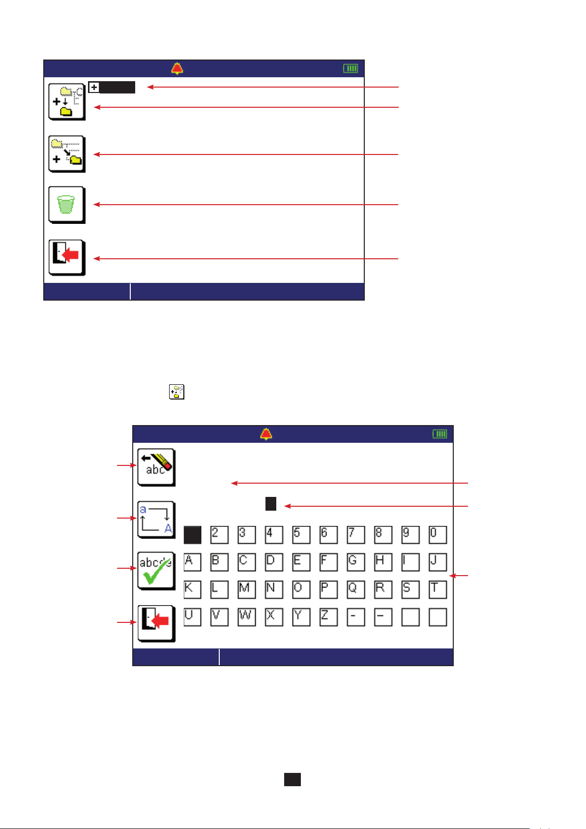
The following screen then appears:
11-25-2013 10:47
Site1
500 kΩ - - .- Hz
Position in the tree.
To create a new SITE.
To create a ROOM in a SITE or an
OBJECT in a ROOM.
To delete an element.
To exit from the memory function.
INSULATION
6.3. CREATE A TREE
As default, the device proposes the beginning of a tree (SITE1, ROOM1, OBJECT1). If you do not want to create a tree, this lets
you record all of your measurements in OBJECT1.
To expand the tree, use the key or the OK key.
To create a new SITE, press the key. The name entry screen is displayed.
11-25-2013 10:47
Erase a letter.
500 kΩ - - .- Hz
/m e m
Change between
upper- and lowercase.
Save and exit.
Exit without saving.
1
INSULATION
S i t e
Path in the tree.
Name of the new
SITE.
Alphanumeric
keyboard.
You can then rename the SITE. Start by erasing the existing text. Then move about on the keyboard using the directional keypad
( ) and validate each letter by pressing the OK key.
A sustained press on one of the keys speeds up the scrolling
69

To add a ROOM to a SITE, place the cursor on the chosen SITE and press the key. Give the ROOM a name and validate it.
Then press the key again to create an OBJECT in the ROOM. This results in the following tree:
11-25-2013 10:47
500 kΩ - - .- Hz
Site1
Room1
Object1
House
Entry
Switchboard
INSULATION
To avoid losing time when you are making the measurements, you can prepare your tree in advance.
6.4. RECORD THE MEASUREMENT
To record the measurement, place the cursor on the desired OBJECT and press the OK key.
For insulation, loop impedance, line impedance, current, and power measurements and the harmonic analysis, the device proposes indexing your measurement, because several measurements are possible.
11-25-2013 10:47
INSULAT. LN
INSULAT.
INSULAT.
INSULAT.
INSULAT.
INSULAT.
INSULAT.
INSULAT.
INSULAT.
INSULAT.
INSULAT.
INSULAT.
INSULAT.
L - N
L - PE
N - PE
L1 - PE
L2 - PE
L3 - PE
L1 - N
L2 - N
L3 - N
L1 - L2
L2 - L3
L1 - L3
500 kΩ - - .- Hz
-
PE
INSULATION
Using the arrows, select the type of insulation measurement you have just made and validate by pressing the OK key.
70

You can in this way make several insulation measurements on the electrical panel. And then move on to another type of measure-
6 %
ment, still on the electrical panel, for example a loop impedance measurement.
11-25-2013 10:47
LOOP Zs
LOOP L - PE
LOOP L1 - PE
LOOP L2 - PE
LOOP L3 - PE
LOOP Zs
6.5. READ THE RECORDS
100 Ω 50 . 1 Hz
As in the case of insulation, you can
index the measurement.
You can read the measurement made by pressing the
last OBJECT on which a measurement has been recorded is selected.
To change levels in the tree, use the and keys.
To move on the same level (from SITE to SITE, ROOM to ROOM, or OBJECT to OBJECT), use the keys.
To see all of the measurements made on the selected OBJECT, press the OK key.
11-25-2013 10:47
500 kΩ - - .- Hz
House / Entry / Switchboard
key (arrow pointing out). The device then displays the tree again. The
Insulation resistance measurements
have been made on this OBJECT
and at least one of them is not OK.
INSULATION
Zs (LOOP)
Loop impedance measurements
have been made on this OBJECT
and they are all OK.
INSULATION
71

Press the OK key to expand a TYPE OF TEST.
11-25-2013 10:47
House / Entry / Switchboard
INSULATION
Zs (LOOP)
INSULATION
Press the OK key again to see the recorded measurement.
1. -
2. -
500 kΩ - - .- Hz
INSULAT. L1-PE
INSULAT. L1-N
LOOP L1-PE1. LOOP L2-PE2. -
Path in the tree.
List of tests performed in the Panel
OBJECT.
OK
11-25-2013 10:47
2 %
INSULAT. L - PE
500 kΩ - - .- Hz
3 1 . 0 6 M Ω
7 s
The top and bottom strips of the
display unit are displayed in reverse
video to clearly differentiate a measurement just made from a reading
in memory.
Indexed measurement.
Press the key to return to the tree.
72

6.6. ERASURE
You can erase a SITE, a ROOM, an OBJECT or a record either when creating the tree or while reading in memory.
Move the cursor onto the element to be erased using the keys of the directional keypad ( ).
11-25-2013 10:47
500 kΩ - - .- Hz
Site1
Room1
Object1
House
Entry
Switchboard
Kitchen
Socket1
Socket1
Socket2
Socket3
INSULATION
Press the key to erase ROOM1. The device asks you to confirm by pressing the OK key or abort by pressing the key.
If the number of measurements recorded is large, the erasure may last several minutes.
6.7. ERRORS
The commonest errors during storage are the following:
The name given already exists. Change the name or index it (ROOM1, ROOM2, etc.)
The memory is full. You must eliminate at least one OBJECT to be able to record your new measurement.
It is not possible to record a measurement in a SITE or a ROOM. You must create an OBJECT in a ROOM or access an exist-
ing OBJECT and record the measurement there.
73

7. DATA EXPORT SOFTWARE
The data export software is in two parts:
ICT (Installation Controller Transfer), used to configure the parameters of the measurements, prepare the tree in memory, and
export the recorded measurements in an Excel file.
Dataview, used to recover the measurements from the Excel file and present them in the form of a report conforming to the
standard in your country.
Start by installing the driver and the software programs using the CD provided with the C.A. 6116.
Then, turn the device on by turning the switch to
any setting.
SET UP
Then connect the device to the PC using the USB cord
provided with the instrument and removing the cover
that protects the USB port of the device.
When the device is in communication with a PC, it
does nothing else and its keys are inactive. It then
displays the following message:
OFF
The data rate is 115,200 Bauds.
To use the data export software, refer to the help functions of the software.
Once the USB cord has been disconnected, the device restarts after a few seconds.
74
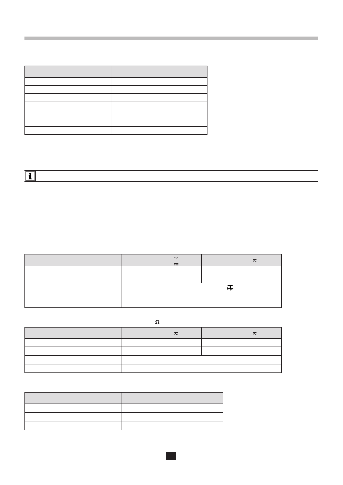
8. TECHNICAL CHARACTERISTICS
8.1. GENERAL REFERENCE CONDITIONS
Quantity of influence Reference values
Temperature 20 ± 3 °C
Relative humidity 45 to 55 % HR
Supply voltage 10.6 ± 0.2 V
Frequency DC and 45 to 65 Hz
Electric field < 1 V/m
Magnetic field < 40 A/m
Supply on battery (mains not connected)
The intrinsic uncertainty is the error defined under the reference conditions.
The operating uncertainty includes the intrinsic uncertainty plus the effects of variation of the quantities of influence (supply
voltage, temperature, interference, etc.) as defined in standard IEC-61557.
The device is not designed to operate when the charger is connected. The measurements must be made using the battery.
8.2. ELECTRICAL CHARACTERISTICS
8.2.1. VOLTAGE MEASUREMENTS
Particular reference conditions:
Peak factor = 1.414 in AC (sinusoidal signal)
AC component <0.1% in DC measurement
DC component <0.1% in AC measurement
Voltage measurements (L, N, PE)
Measurement range (AC or DC)
Resolution 0.1 V 1 V
Intrinsic uncertainty ± (1.5 % + 2 ct) ± (1.5 % + 1 ct)
Input impedance
Frequency of use DC and 15.8 to 450 Hz
Voltage measurements in insulation measurement (MW, PE)
Measurement range (AC or DC) 5,0 - 399,9 V 400 - 550 V
Resolution 0,1 V 1 V
Intrinsic uncertainty ± (3,7 % + 2 pt) ± (3,7 % + 1 pt)
Input impedance 145 kW
Frequency of use DC and 15.8 to 65 Hz
0.2 - 399.9 V
2.0 - 399.9 V
270 kW between terminals L, N, and PE
530 kW between terminals L and N
400 - 550 V
Contact voltage measurements
Measurement range (AC) 2.0 - 100.0 V
Intrinsic uncertainty ± (15% + 2 ct)
Input impedance 6 MW
Frequency of use 15.8 … 65 Hz
This voltage is displayed only if it exceeds UL (25 V, 50 V or 65 V).
75

Measurements of potential of the voltage probe
The characteristics are the same as in the voltage measurements except that the input impedance is 200 kW.
This voltage must normally be between 0 and UL.
8.2.2. FREQUENCY MEASUREMENTS
Particular reference conditions:
Voltage ≥ 2 V
Voltage ≥ 20 V
or current ≥ 30 mA for the MN77 clamp,
≥ 50 mA for the C177A clamp.
Beyond these values, the frequency is indeterminate (display of - - - - ).
Measurement range 15.8 - 399.9 Hz 400.0 - 499.9 Hz
Resolution 0.1 Hz 1 Hz
Intrinsic uncertainty
8.2.3. CONTINUITY MEASUREMENTS
Particular reference conditions:
Resistance of the leads: zero or compensated.
Inductance of the leads: zero.
External voltage on the terminals: zero.
Inductance in series with the resistance: zero.
for the MW voltage input
± (0.1 % + 1 ct)
Compensation of the leads up to 5 W.
The maximum acceptable superposed external AC voltage is 0.5 VRMS in sine wave.
200 mA current
Measurement range 0.00 - 39.99 W
Resolution 0.01 W
Measurement current ≥ 200 mA
Intrinsic uncertainty ± (1.5% + 2 ct)
Operating uncertainty ± (8.5% + 2 ct)
No-load voltage 9.5 V ± 10%
Maximum inductance in series 40 mH
12 mA current
Measurement range 0.00 - 39.99 W 40.0 - 399.9 W
Resolution 0.01 W 0.1 W
Measurement current 12 mA
Intrinsic uncertainty ± (1.5% + 5 ct)
Operating uncertainty ± (8.5% + 5 ct)
No-load voltage 9.5 V ± 10%
Maximum inductance in series 40 mH
76

8.2.4. RESISTANCE MEASUREMENTS
RN = UN / 1 mA
Particular reference conditions:
External voltage on the terminals: zero.
Inductance in series with the resistance: zero.
Measurement range 0.001 - 3.999 kW 4.00 - 39.99 kW 40.0 - 399.9 kW
Resolution 1 W 10 W 100 W
Measurement current ≤ 22 µA
Intrinsic uncertainty ± (1.5% + 5 ct)
≤ 22 µA ≤ 17 µA
± (1.5% + 2 ct) ± (1.5% + 2 ct)
No-load voltage 3.1 V ± 10%
8.2.5. INSULATION RESISTANCE MEASUREMENTS
Particular reference conditions:
Capacitance in parallel: zero.
Maximum acceptable external AC voltage during the measurement: zero.
Frequency of external voltages: DC and 15.8 ... 65 Hz.
The frequency is guaranteed only for a voltage ≥ 20 V .
Maximum no-load voltage 1.254 x UN (for UN ≥ 100 V)
No-load voltage (50 V range) 48 V ≤ U ≤ 70 V)
Nominal current ≥ 1 mA
Short-circuit current ≤ 3 mA
External AC voltage on the terminals zero
Intrinsic uncertainty on the measurement of the test voltage ± (2.5% + 3 ct)
Measurement range at 50 V 0.01 - 7.99 MW 8.00 - 39.99 MW
Measurement range at 100 V 0.01 - 3.99 MW 4.00 - 39,99 MW
Measurement range at 250 V 0.01 - 1.99 MW 2.00 - 39.99 MW
40.0 - 399.9 MW 400 - 1999 MW
Measurement range at 500 V 0.01 - 0.99 MW 1.00 - 39.99 MW
Measurement range at 1000 V 0.01 - 0.49 MW 0.50 - 39.99 MW
Resolution 10 kW 10 kW 100 kW 1 MW
50V range:
Intrinsic uncertainty ± (5% + 3 ct) ± (2% + 2 ct) ± (2% + 2 ct)
Value for guidance
Other ranges:
± (2% + 2 ct)
50V range:
Uncertainty of operation ± (12% + 3 ct) ± (10% + 2 ct) ± (10% + 2 ct)
Value for guidance
Other ranges:
± (10% + 2 ct)
Typical test voltage vs load curve
The voltage developed as a function of the resistance measured has the following form:
I = 1 mA
U
N
77
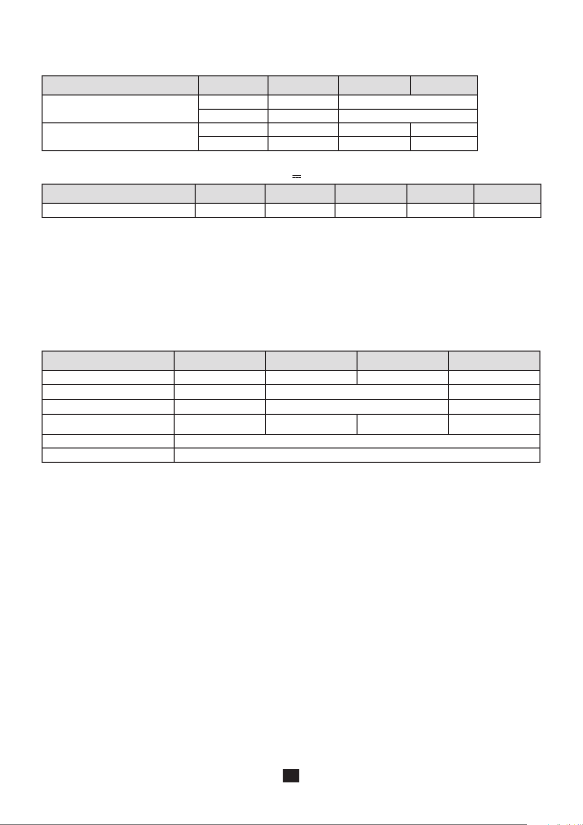
Typical measurement settling time as a function of the elements tested
These values include influences due to the capacitive component of the load, to the automatic range system, and to the regulation of the test voltage.
Test voltage Load Non-capacitive With 100 nF With 1 µF
50 V - 250 V
250 V - 500 V - 1000 V
10 MW 1 s -
1000 MW 1 s -
10 MW 1 s 2 s 12 s
1000 MW 1 s 4 s 30 s
Typical discharge time of a capacitive element to reach 25 V
Test voltage 50 V 100 V 250 V 500 V 1000 V
Discharge time (C in µF) 0,25 s x C 0,5 s x C 1 s x C 2 s x C 4 s x C
8.2.6. 3P EARTH RESISTANCE MEASUREMENTS
Particular reference conditions:
Resistance of the E lead: zero or compensated.
Interference voltages: zero.
Inductance in series with the resistance: zero.
(RH + RS ) / RE < 300 and RE < 100 x RH with RH and RS ≤ 15,00 kW.
Compensation of the lead RE up to 2.5 W.
Measurement range 0.50 - 39.99 W 40.0 - 399.9 W 400 - 3999 W 0.20 - 15.00 kW
Resolution 0.01 W 0.1 W 1 W 10 W
Intrinsic uncertainty ± (2% + 10 ct) ± (2% + 2 ct) ± (10% + 2 ct)
Operating uncertainty ± (9% + 20 ct) ± (9% + 5 ct) -
Typical peak-to-peak measurement current
2
4.3 mA 4.2 mA 3.5 mA -
Measurement frequency 128 Hz
No-load voltage 38.5 V peak-to-peak
1
1: the 40 kW display range is used only for measurements of the RH and RS rods.
2: current at mid-range with RH = 1000 W.
Maximum acceptable interference voltage:
25 V on H from 50 to 500 Hz.
25 V on S from 50 to 500 Hz.
Accuracy on the measurement of the interference voltages:
Characteristics the same as for the voltage measurements in §8.2.1.
8.2.7. EARTH MEASUREMENTS ON LIVE CIRCUITS
Particular reference conditions:
Voltage of the installation: 90 to 500 V.
Stability of the voltage source: < 0.05%.
Frequency of the installation: 15.8 to 17.5 Hz and 45 to 65 Hz.
Resistance of the leads: zero or compensated.
Impedance of the inductive part: < 0.1 x the resistive part of the impedance measured
Contact voltage (potential of the protective conductor with respect to the local earth): < 5 V.
Resistance of the voltage measurement probe: ≤ 15 kW.
Potential of the voltage probe with respect to the PE: ≤ UL.
Residual leakage current of the installation: zero.
Compensation of the lead RE up to 2.5 W.
78

Characteristics in trip mode:
Measurement range 0.100 - 0.500 W 0.510 - 3.999 W 4.00 - 39.99 W 40.0 - 399.9 W
Resolution 0.001 W 0.01 W 0.1 W
Intrinsic uncertainty on the impedance measurement ± (10% + 20 ct) ± (5% + 20 ct) ± (5% + 2 ct)
Peak measurement current between 90 and 270 V 2,45 - 7,57 A 2,27 - 7,55 A 1,36 - 7,02 A 0,274 - 4,20 A
Peak measurement current between 270 and 550 V 4,48 - 6,66 A 4,3 - 6,66 A 3,05 - 6,39 A 0,78 - 4,53 A
Intrinsic uncertainty on the resistive part ± (10% + 20 ct) ± (5% + 20 ct) ± (5% + 2 ct)
Intrinsic uncertainty on the inductive part
Operating uncertainty on the impedance measurement ± (17% + 20 ct) ± (12% + 20 ct) ± (12% + 2 ct)
Frequency of operation 15.8 to 17.5 and 45 to 65 Hz
3
± (10% + 2 ct) ± (10% + 2 ct)
-
3: the inductive part is displayed only when the impedance is ≤ 30 W.
The duration of the measurement depends on the voltage of the installation, on the measured impedance value, and on the activation of the smoothing filter (SMOOTH).
If smoothing is activated (SMOOTH mode), the instability of the intrinsic uncertainty is then halved (for example: ±5 digits becomes ±2.5 digits).
Maximum acceptable resistance of the voltage probe: 15 kW.
Intrinsic uncertainty on the probe resistance measurement: ± (10% + 5 digits), resolution 0.1 kW.
Maximum acceptable inductance for the measurement: 15 mH, resolution 0.1 mH.
Calculation of the fault voltage if there is a short-circuit, UFk:
Calculation range 0.2 - 399.9 V 400 - 550 V
Resolution 0.1 V 1 V
Intrinsic uncertainty
= √ (Intrinsic uncertainty on the voltage measurement if U
+ (Intrinsic uncertainty on the loop measurement)²
is used)²
MEAS
Frequency of operation 15,8 to 17,5 and 45 to 65 Hz
Characteristics in non-tripping mode:
Measurement range 0.20 - 0.99 W 1.00 - 1.99 W 2.00 - 39.99 W 40.0 - 399.9 W 400 - 3999 W
Resolution 0.01 W 0.1 W 1 W
RMS measurement current choice of 6. 9. or 12 mA
Intrinsic uncertainty on the impedance measurement
4
Intrinsic uncertainty on the
resistive part
Intrinsic uncertainty on the
inductive part
Operating uncertainty on the
impedance measurement
± (15% + 10 ct) ± (15% + 3 ct) ± (10% + 3 ct) ± (5% + 2 ct)
± (15% + 10 ct) ± (15% + 3 ct) ± (10% + 3 ct) ± (5% + 2 ct)
± (10% + 10 ct) ± (10% + 3 ct) ± (10% + 3 ct) ± (5% + 2 ct)
± (20% + 10 ct) ± (20% + 3 ct) ± (12% + 3 ct) - -
4: There is no measurement of the inductive in L-PE loop part with a low current.
The intrinsic uncertainty is defined for 0.1 ≤ RL / RN ≤ 10 with RL and RN ≥ 1 W.
The duration of the measurement depends on the voltage of the installation, on the measured impedance value, and on the activation of the smoothing filter (SMOOTH).
If smoothing is activated (SMOOTH mode), the instability of the intrinsic uncertainty is then halved (for example: ±5 digits becomes
±2.5 digits) and the duration of the measurement is of the order of 30 s.
Maximum acceptable resistance of the voltage probe: 15 kW.
Intrinsic uncertainty on the probe resistance measurement: ± (10% + 5 digits), resolution 0.1 kW.
Maximum acceptable inductance for the measurement: 13,17 mH with R < 0,50 W.
79

Characteristics in selective mode:
Measurement range 0.50 - 39.99 W 40.0 - 399.9 W
Resolution 0.01 W 0.1 W
Intrinsic uncertainty on the re-
sistance measurement
5
± (10% + 10 ct)
5: there is no measurement of the inductive part in selective mode.
The duration of the measurement depends on the voltage of the installation, on the measured impedance value, and on the activation of the smoothing filter (SMOOTH).
Maximum acceptable resistance of the voltage probe: 15 kW.
Accuracy on the probe resistance measurement: ± (10% + 5 digits), resolution 0.1 kW.
The measurement current corresponds to the test current indicated in the table of characteristics in tripping mode divided by the
ratio R
SEL/RA
avec R
≤ 100. Beyond this, the maximum current, 20 mA peak, is reached.
SEL/RA
8.2.8. LOOP IMPEDANCE MEASUREMENTS
Particular reference conditions:
Voltage of the installation: 90 to 500 V.
Stability of the voltage source: <0.05%.
Frequency of the installation: 15.8 to 17.5 Hz and 45 to 65 Hz.
Resistance of the leads: zero or compensated.
Contact voltage (potential of the protective conductor with respect to the local earth): < 5 V.
Residual leakage current of the installation: zero.
Compensation of the leads up to 5 W.
Characteristics in 3-wire mode with tripping:
See § 8.2.7
Characteristics in 3-wire mode without tripping:
See § 8.2.7
Characteristics of the short-circuit current calculation:
Calculation formula : Ik = U
REF
/ ZS
Calculation range 0.1 - 399.9 A 400 - 3999 A 4.00 - 6.00 kA
Resolution 0.1 A 1 A 10 A
Intrinsic uncertainty
Operating uncertainty
= √ (Intrinsic uncertainty on the voltage measurement if U
+ (Intrinsic uncertainty on the loop measurement)²
= √ (Operating uncertainty on the voltage measurement if U
+ (Operating uncertainty on the loop measurement)²
is used)²
MEAS
MEAS
is used)²
8.2.9. LINE IMPEDANCE MEASUREMENTS
Particular reference conditions:
Voltage of the installation: 90 to 500 V.
Stability of the voltage source: <0.05%.
Frequency of the installation: 15.8 to 17.5 Hz and 45 to 65 Hz.
Resistance of the leads: zero or compensated.
Impedance of the inductive part: < 0.1 x the resistive part of the impedance measured
Compensation of the leads up to 5 W.
Characteristics in 2-wire mode (power-level current):
See § 8.2.7
80

8.2.10. VOLTAGE DROP IN THE CABLES
Particular reference conditions:
Voltage of the installation: 90 to 500 V.
Stability of the voltage source: <0.05%.
Frequency of the installation: 15.8 to 17.5 Hz and 45 to 65 Hz.
Resistance of the leads: zero or compensated.
Impedance of the inductive part: < 0.1 x the resistive part of the impedance measured
Compensation of the leads up to 5 W.
The voltage drop is a calculated value.
Calculation formula: DV = 100 (Zi - Zi ref ) x IN / U
REF
Calculation range -40% to +40%
Resolution 0,01%
8.2.11. TEST OF RESIDUAL CURRENT DEVICE
Particular reference conditions:
Voltage of the installation: 90 to 500 V.
Frequency of the installation: 15.8 to 17.5 Hz and 45 to 65 Hz.
Contact voltage (potential of the protective conductor with respect to the local earth): <5 V.
Resistance of the voltage probe (if used): < 100 W.
Potential of the voltage measurement (if used) with respect to the PE: <5 V..
Residual leakage current of the installation: zero.
Limitation of the ranges accessible as a function of the voltage for type AC and A RCDs
I
DN
90 - 280 V
280 - 550 V
10 mA 30 mA 100 mA 300 mA 500 mA 650 mA 1000 mA Variable
≥ 100 V I
≤ 950 mA
DN
I
≤ 500 mA
DN
Limitation of the test current as a function of the nature of the test signal for type AC and A RCDs
Depending on the range IDN chosen and the nature of the test signal, some test modes will be unavailable. This test of coherence
is performed when the test of RCDs is started..
Wave or
I 10 mA 30 mA 100 mA 300 mA 500 mA 650 mA 1000 mA Variable
Ramp
I
pulse
DN
2 x IDN pulse
5 x IDN pulse
I
≤ 500 mA
DN
I
≤ 200 mA
DN
Wave or
I 10 mA 30 mA 100 mA 300 mA 500 mA 650 mA 1000 mA Variable
Ramp
I
pulse
DN
2 x IDN pulse
5 x IDN pulse
81
I
≤ 500 mA
DN
I
≤ 500 mA
DN
I
≤ 250 mA
DN
I
≤ 100 mA
DN
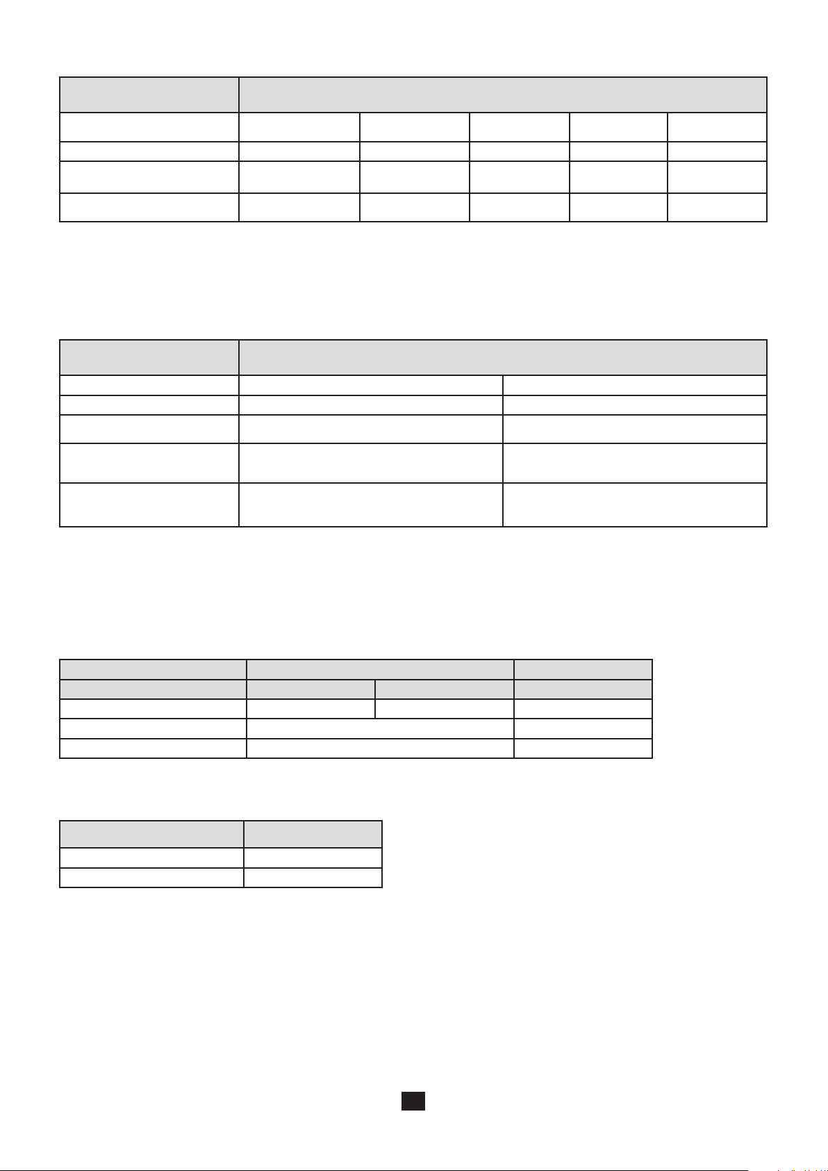
Characteristics in pulse mode for type AC and A RCDs:
Range I
DN
Nature of the test Determination of UFNon-tripping test Tripping test
Test current 0.2 x IDN … 0.5 x I
Intrinsic uncertainty on the test
current
Maximum duration of application of the test current
+0 -7%
± 2 mA
from 32 to 72
periods
10 mA - 30 mA - 100 mA - 300 mA - 500 mA - 650 mA - 1000 mA
Variable (6 to 999 mA)
6
Tripping test (se-
lective)
7
DN
0.5 x I
+0 -7%
± 2 mA
DN
I
DN
-0 +7%
± 2 mA
2 x I
DN
-0 +7%
± 2 mA
1000 or 2000 ms 8 300 ms 150 ms 40 ms
Tripping test
5 x I
DN
-0 +7%
± 2 mA
6: the upper limit of the variable range (999 mA) depends on the nature of the test performed and on the type of test current (half
or full wave).
7: this current can be adjusted in steps of 0.1 IDN and must not be less than 4 mA. As default, this current is 0.3 IDN.
8: to be chosen when configuring the measurement.
Characteristics in ramp mode for type AC and A RCDs:
Range I
DN
Nature of the test Determination of U
Test current 0.2 x IDN … 0.5 x I
Intrinsic uncertainty on the test
current
Maximum duration of application of the test current
Intrinsic uncertainty on the indication of the tripping current
10 mA - 30 mA - 100 mA - 300 mA - 500 mA - 650 mA - 1000 mA
Variable (6 to 999 mA)
F
10
DN
9
Tripping test
0.9573 x IDN x k / 28
+0 -7% ± 2 mA -0 +7% ± 2 mA
from 32 to 72 periods
4600 ms to 50 and 60 Hz
4140 ms to 16.6 Hz
-0 +7% + 3.3 % IDN ± 2 mA
-
Resolution de 0.1 mA up to 400 mA
and 1 mA thereafter
11
9: the upper limit of the variable range (999 mA) depends on the nature of the test performed and on the type of test current (half
or full wave).
10: this current can be adjusted in steps of 0.1 IDN and must not be less than 4 mA. As default, this current is 0.3 IDN.
11: k is between 9 and 31. The waveform so generated goes from 0.3 IDN to 1.06 IDN in 22 steps of 3.3% IDN each having a duration
of 200 ms (180 ms at 16.66Hz).
Characteristics of the trip time (TA) for type AC and A RCDs:
Pulse mode Ramp mode
Measurement range 5.0 - 399.9 ms 400 - 500 ms 10.0 - 200.0 ms
Resolution 0.1 ms 1 ms 0.1 ms
Intrinsic uncertainty ± 2 ms ± 2 ms
Operating uncertainty ± 3 ms ± 3 ms
Characteristics of the fault voltage calculation (UF) for type AC and A RCDs:
Measurement range 5.0 - 70.0 V
Resolution 0.1 V
Intrinsic uncertainty ± (10% + 10 ct)
Calculation formula:
UF = Z
x IDN or ZA x IDN or RA x IDN or Z
LPE
x 2IDN if the test is at 2I
LPE
DN
82

Limitation of the ranges available as a function of the voltage for type B RCDs
I
DN
90 - 280 V
280 - 550 V
10 mA 30 mA 100 mA 300 mA 500 mA 650 mA 1000 mA Variable
Limitation of the test current as a function of the nature of the test signal for type B RCDs
Depending on the range IDN chosen and the nature of the test signal, some test modes will be unavailable. This test of coherence
is performed when the test of RCDs is started.
Wave or
I 10 mA 30 mA 100 mA 300 mA 500 mA 650 mA 1000 mA Variable
Ramp
2 x IDN pulse
4 x IDN pulse
Characteristics in pulse mode for type B RCDs:
Range I
DN
10 mA - 30 mA - 100 mA - 300 mA - 500 mA
Nature of the test Tripping test Tripping test
Test current 2.2 x 2 I
Intrinsic uncertainty on the test
current
Maximum duration of application of the test current
-0 + 3.5%
± 2 mA
300 ms 150 ms
DN
2.4 x 4 I
DN
-0 + 3.5%
± 2 mA
12: this current can be adjusted in steps of 0.1 IDN and must not be less than 10 mA. As default, this current is 0.2 IDN.
Characteristics in ramp mode for type B RCDs:
Range I
DN
10 mA - 30 mA - 100 mA - 300 mA - 500 mA
Nature of the test Tripping test
Test current 0.2 to 2.2 x I
Intrinsic uncertainty on the test
current
Maximum duration of application of the test current
Intrinsic uncertainty on the indication of the tripping current
Resolution de 0.1 mA up to 400 mA
-0 +7% ± 2 mA
6000 ms
(-0 +7% + 3.3 % IDN ± 2 mA
and 1 mA thereafter
DN
Characteristics of the trip time (TA) for type B RCDs:
Pulse mode
Measurement range 5.0 - 399.9 ms 400 - 500 ms
Resolution 0.1 ms 1 ms
Intrinsic uncertainty ± 2 ms
Operating uncertainty ± 3 ms
The tripping time is not displayed.
83

8.2.12. CURRENT MEASUREMENT
Particular reference conditions:
Peak factor = 1,414
DC component< 0.1 %.
Frequency: 15.8 450 Hz.
For the measurement of I
, the intrinsic uncertainty is increased by 5%.
SEL
Characteristics with the MN77 clamp:
Transformation ratio: 1000 / 1
Measurement range 5.0 - 399.9 mA 0.400 - 3.999 A 4.00 - 19.99 A
Resolution 0.1 mA 1 mA 10 mA
Intrinsic uncertainty ± (2% + 5 ct) ± (1.5% + 2 ct) ± (1.2% + 2 ct)
When a voltage is connected between the L and PE terminals, the device synchronizes to the frequency of this voltage, allowing
current measurements from 1 mA.
Characteristics with the C177A clamp:
Transformation ratio: 10 000 / 1
Measurement range 5.0 - 399.9 mA 0.400 - 3.999 A 4.00 - 39.99 A 40.0 - 199.9 A
Resolution 0.1 mA 1 mA 10 mA 100 mA
Intrinsic uncertainty ± (2% + 5 ct) ± (1.5% + 2 ct) ± (1% + 2 ct) ± (1.2% + 2 ct)
When a voltage is connected between the L and PE terminals, the device synchronizes to the frequency of this voltage, allowing
current measurements from 5 mA.
In selective current measurements, the intrinsic error of the clamps is increased by 5 %.
8.2.13. DIRECTION OF PHASE ROTATION
Particular reference conditions:
Three-phase network.
Voltage of the installation: 20 to 500 V.
Frequency: 15.8 to 17. 5 Hz and 45 to 65 Hz.
Acceptable level of amplitude unbalance: 20%.
Acceptable level of phase unbalance: 10%.
Acceptable level of harmonics (voltage): 10%.
Characteristics:
The phase order is «positive» if rotation L1-L2-L3 is anticlockwise.
The phase order is «negative» if rotation L1-L2-L3 is clockwise.
The three voltages are measured (see the characteristics in §8.2.1) and indicated as U12, U23 and U31.
84

8.2.14. POWER MEASUREMENTS
Particular reference conditions:
Sinusoidal voltage and current signals: cosj = 1.
Voltage ≥ 10 V.
Current ≥ 0.1 A (for the C177A clamp).
Frequency: 15.8 to 17.5 Hz and 45 to 65 Hz.
No DC component.
Measurement range 5 - 3999 W 4.00 - 39.99 kW
40.0 - 110.0 kW
40.0 - 330.0 kW
13
Resolution 1 W 10 W 100 W
Intrinsic uncertainty ± (2% + 5 ct) ± (2% + 2 ct) ± (2% + 2 ct)
13: full scale is 110 kW (550V x 200A) in single-phase and 330 kW in three-phase.
8.2.15. POWER FACTOR
Particular reference conditions:
Voltage of the installation: 10 to 500 V.
Current: 0.1 to 200 A.
Measurement range (±) 0.2 - 0.49 (±) 0.50 - 1.00
Resolution 0.01
Intrinsic uncertainty ± (2% + 2 ct) ± (1% + 2 ct)
If the power is zero, the power factor is indeterminate.
The sign of the power factor depends on whether the phase of the voltage leads or lags that of the current. This can be used to
determine whether the load is inductive (+ sign) or capacitive (- sign).
8.2.16. HARMONICS
Particular reference conditions:
Signal without inter-harmonics, of which the fundamental is stronger than the other harmonic components and than the DC
component.
Frequency of the fundamental: 16.66 Hz, 50 Hz, or 60 Hz ± 0.05 Hz.
Peak factor of the signal ≤ 4.
Characteristics:
Characteristics of voltage display
Characteristics of current display
10 to 500 V, the display range being determined by the value of the
strongest harmonic component.
1 to 200 A, the display range being determined by the value of the
strongest harmonic component.
Stability of the current and voltage display ± 2 ct
Domain of use Harmonics of orders 1 to 50
Measurement range for the harmonic factor 0.2 - 399.9 %
Detection threshold for the harmonic factor 0.1 %
Measurement range in THD-F and THD-R 0.2 - 100 %
Resolution for the harmonic factor, THD-F and THD-R 0.1%
Factor > 10% and order < 13: 5 ct
Intrinsic uncertainty on the RMS value and the harmonic
factor
Factor <10% and order < 13: 10 ct
Factor > 10% and order > 13: 10 ct
Factor > 10% and order > 13: 15 ct
Intrinsic uncertainty on the THD-F and THD-R 10 ct
85

Method and definitions:
Determination of harmonics: Cooley-Tukey FFT algorithm on 16 bits
Sampling frequency: 256 times the frequency of the fundamental
Filtering window: rectangular, 4 periods
THD-F: Total distortion referred to the fundamental of the signal.
n=50
Hn²
Σ
√
THD-F =
THD-R: Total distortion referred to the RMS value of the signal (also called DF: distortion factor).
THD-R =
n=2
H
n=50
Σ
√
n=2
R[RMS]
1
Hn²
8.3. VARIATIONS IN THE RANGE OF USE
8.3.1. VOLTAGE MEASUREMENT
Quantities of influence Limits of the range of use
Temperature -10 … + 55 °C 1 %/10 °C ± 1 ct 2 %/10 °C + 2 ct
Relative humidity 10 … 85 % RH at 45°C 2 % 3 % + 2 ct
Supply voltage 8.4 … 12.7 V 0.1% or 1 ct 0.5% + 2 ct
Frequency (except in MW setting) 15.8 … 450 Hz 0,5% 4,5 % + 1 ct
Frequency (in MW setting) 15.8 … 65 Hz 4% 1% + 1 ct
Series mode rejection in AC
0 … 500 Vac 50 dB 40 dB50/60Hz series mode rejection in DC
Common mode rejection in 50/60Hz AC
8.3.2. INSULATION MEASUREMENT
Quantities of influence Limits of the range of use
Temperature -10 … + 55 °C 1 %/10 °C ± 1 ct 2 %/10 °C + 2 ct
Relative humidity 10 … 85 % RH at 45°C 2 % 3 % + 2 ct
Supply voltage 8.4 … 12.7 V 0.25% or 2 ct 2% + 2 ct
Ranges 50 V and 100 V
R ≤ 100 MW : 2 V
R > 100 MW : 0,7 V
Variation of the measurement
Typical Maximum
Variation of the measurement
Typical Maximum
50/60Hz AC voltage superposed on the
test voltage (UN)
Capacitance in parallel on the resistance
to be measured
Ranges 250 V and 500 V
R ≤ 100 MW : 6 V
R > 100 MW : 2 V
Ranges 500 V and 1000 V
R ≤ 100 MW : 10 V
R > 100 MW : 3 V
0 … 5 µF @ 1 mA
0 … 2 µF @ 2000 MW
86
1% 5% + 2 ct
1%
1%
1% + 1 ct
10% + 5 ct

8.3.3. RESISTANCE AND CONTINUITY MEASUREMENT
Quantities of influence Limits of the range of use
Temperature -10 … + 55 °C 1 %/10 °C ± 1 ct 2 %/10 °C + 2 ct
Relative humidity 10 … 85 % RH at 45°C 2 % 3 % + 2 ct
Supply voltage 8.4 … 12.7 V 0.25% or 1 ct 1% + 2 ct
50/60Hz AC voltage superposed on the
test voltage
8.3.4. 3P EARTH MEASUREMENT
Quantities of influence Limits of the range of use
Temperature -10 … + 55 °C 1 %/10 °C ± 1 ct 2 %/10 °C + 2 ct
Relative humidity 10 … 85 % RH at 45°C 2 % 3 % + 2 ct
Supply voltage 8.4 … 12.7 V 0.25% or 1 ct 1% + 2 ct
Voltage in series in the voltage measurement loop (S-E)
Fundamental = 16.6/50/60Hz + odd
harmonics
Voltage in series in the current injection
loop (H-E)
Fundamental = 16.6/50/60Hz + odd
harmonics
Current loop rod resistance (RH) 0 to 15 kW 0.3% 1% + 2 ct
Voltage loop rod resistance (RS) 0 to 15 kW 0.3% 1% + 2 ct
0.5 Vac 0,5% 1% + 2 ct
15 V (RE ≤ 40 W)
25 V (RE > 40 W)
15 V (RE ≤ 40 W)
25 V (RE > 40 W)
Variation of the measurement
Typical Maximum
Variation of the measurement
Typical Maximum
0.5% or 10 ct
0.5% or 10 ct
2% + 50 ct
2% + 2 ct
2% + 50 ct
2% + 2 ct
8.3.5. CURRENT MEASUREMENT
Quantities of influence Limits of the range of use
Temperature -10 … + 55 °C 1 %/10 °C ± 1 ct 2 %/10 °C + 2 ct
Relative humidity 10 … 85 % RH at 45°C 2 % 3 % + 2 ct
Supply voltage 8.4 … 12.7 V 0.1% or 2 ct 0.5% + 2 ct
Frequency
50/60Hz series mode rejection in AC 0 … 500 Vac 50 dB 40 dB
15.8 … 45 Hz
45 … 450 Hz
Variation of the measurement
Typical Maximum
1%
0.5%
1% + 1 ct
1.5% + 1 ct
87

8.3.6. EARTH MEASUREMENT ON LIVE CIRCUIT, LOOP AND SELECTIVE EARTH
Quantities of influence Limits of the range of use
Temperature -10 … + 55 °C 1 %/10 °C ± 1 ct 2 %/10 °C + 2 ct
Relative humidity 10 … 85 % RH at 45°C 2 % 3 % + 2 ct
Supply voltage 8.4 … 12.7 V 0.5% or 2 ct 2% + 2 ct
Network frequency of the installation
tested
Network voltage of the installation tested
Phase difference between the internal load
and the measured impedance or inductance of the measured impedance or L/R
ratio of the measured impedance
Resistance in series with the voltage probe
(earth on live circuit only)
Contact voltage (UC) 0 … 50 V
8.3.7. TEST OF RESIDUAL CURRENT DEVICE
Quantities of influence Limits of the range of use
Temperature -10 … + 55 °C 1 %/10 °C ± 1 ct 2 %/10 °C + 2 ct
Relative humidity 10 … 85 % RH at 45°C 2 % 3 % + 2 ct
Supply voltage 8.4 … 12.7 V 0.1% or 1 ct 0.5% + 2 ct
Network frequency of the installation
tested
Network voltage of the installation tested
99 to 101% of the nominal
frequency
85 to 110% of the nominal
voltage
0 …20°
or 0 … 400 mH
or 0 … 500 ms
0 … 15 kW
99 to 101% of the nominal
frequency
85 to 110% of the nominal
voltage
(taken into account in the
intrinsic uncertainty)
(taken into account in the
intrinsic uncertainty)
Variation of the measurement
Typical Maximum
0.1% or 1 ct 0.1% + 1 ct
0.1% or 1 ct 0.1% + 1 ct
1%/10° 1%/10°
Negligible
(taken into account in the
Negligible
(taken into account in the
Variation of the measurement
Typical Maximum
0.1% or 1 ct 0.1% + 1 ct
0.1% or 1 ct 0.1% + 1 ct
Negligible
intrinsic uncertainty)
Negligible
intrinsic uncertainty)
8.3.8. DIRECTION OF PHASE ROTATION
No quantity of influence
8.3.9. POWER
Quantities of influence Limits of the range of use
Temperature -10 … + 55 °C 1 %/10 °C ± 1 ct 2 %/10 °C + 2 ct
Relative humidity 10 … 85 % RH at 45°C 2 % 3 % + 2 ct
Supply voltage 8.4 … 12.7 V 0.1% or 1 ct 0.5% + 2 ct
Network frequency of the installation
tested
Network voltage of the installation
tested
Power factor
8.3.10. VOLTAGE AND CURRENT HARMONICS
The quantities of influence and the associated variations are the same as for voltage measurements and current measurements,
respectively.
99 to 101% of the nominal
frequency
85 to 110% of the nominal
voltage
0.50 … 1.00 at 45…65 Hz
0.20 … 0.49 at 45…65 Hz
0.50 … 1.00 at 15.8…17.5 Hz
0.20 … 0.49 at 15.8…17.5 Hz
Variation of the measurement
Typical Maximum
0.1% or 1 ct 0.1% + 1 ct
0.1% or 1 ct 0.1% + 1 ct
0.5%
1.5%
2%
4%
1% + 2 ct
3% + 2 ct
2.5% + 2 ct
5% + 2 ct
88

8.4. INTRINSIC UNCERTAINTY AND OPERATING UNCERTAINTY
The installation testers complie with standard IEC-61557, which requires that the operating uncertainty, called B, be less than 30%.
In insulation, B = ± ( |A| + 1,15 √ E1² + E2² + E3² )
with A = intrinsic uncertainty
E1 = influence of the reference position ± 90°.
E2 = influence of the supply voltage within the limits indicated by the manufacturer
E3 = influence of the temperature between 0 and 35°C.
In continuity measurement, B = ± ( |A| + 1,15 √ E1² + E2² + E3² )
In loop measurement, B = ± ( |A| + 1,15 √ E1² + E2² + E3² + E6² + E7² + E8² )
with E6 = influence of the phase angle from 0 to 18°.
E7 = influence of the network frequency from 99 to 101% of the nominal frequency.
E8 = influence of the network voltage from 85 to 110% of the nominal voltage.
In earth measurement, B = ± ( |A| + 1,15 √ E1² + E2² + E3² + E4² + E5² + E7² + E8² )
with E4 = influence of the interference voltage in series mode (3 V at 16.6, 50, 60, and 400 Hz)
E5 = influence of the resistance of the rods from 0 to 100 x RA but ≤ 50 kW.
In test of residual current device, B = ± ( |A| + 1,15 √ E1² + E2² + E3² + E5² + E8² )
with E5 = influence of the resistance of the probes within the limits indicated by the manufacturer.
8.5. POWER SUPPLY
The device is powered by a10.8 V 5.8 Ah rechargeable Lithum-ion battery pack.
8.5.1. LITHIUM-ION TECHNOLOGY
The Li-ion technology has many advantages:
long life between charges with limited bulk and weight,
no memory effect: you can recharge your battery even if it is not fully discharged, without reducing its capacity,
very low self discharge,
the possibility of recharging your battery rapidly,
protection of the environment through the absence of polluting materials such as lead and cadmium.
8.5.2. BATTERY CHARGE
The instrument is not designed to operate when the charger is connected. The measurements must be made using battery
power.
The battery charger of the device is in two distinct parts: an external power supply and a charger built into the device.
The charger manages the charging current, the battery voltage, and the internal temperature of the battery simultaneously. This
optimizes charging while guaranteeing a long battery life.
The day before you use your device, check its charge condition. If the battery level indicator shows less than three bars, charge
the device overnight (see §1.2).
The charging time is approximately 5 h.
In order to extend the life of your battery:
Use only the charger supplied with your device. The use of another charger may prove dangerous!
Charge your device only between 0 and 45°C.
Observe the conditions of use and storage stated in this data sheet.
Following prolonged storage, the battery may be fully discharged. In this case, the first charge may take longer.
89

Set the switch to OFF; charging is possible when the device is not off, but will take longer.
8.5.3. OPTIMIZE BATTERY CHARGING
During charging, the temperature of the battery rises, especially towards the end. A safety device, built into the battery, checks
constantly that the battery temperature does not exceed an acceptable maximum. If this maximum is exceeded, the charger
switches off automatically, even if charging is not complete.
The battery is at the bottom of the device, and the evacuation of the heat can be facilitated by placing the device upright while
charging. The battery temperature is then lower and it will be charged more fully.
This precaution is especially important when the air temperature is high (in summer).
8.5.4. LIFE BETWEEN CHARGES
The mean battery life depends on the type of measurement and on how the device is used. Approximately:
12 h if the automatic switching off function is deactivated,
24 h if the automatic switching off function is activated,
How long your device can operate when the battery is fully charged depends on several factors:
The consumption of the device, which depends on the measurements you make,
The capacity of the battery. It is greatest when the battery is new, and declines as the battery ages.
Here are a few ways to extend battery life between charges:
Use the back-lighting only when it is strictly necessary,
Set the brightness of the display to the lowest level at which you can still read the display unit,
Program the shortest time to automatic switching off you are comfortable with (see SET-UP, § 5),
Use the pulse mode for continuity measurements at 200 mA,
If the continuity measurement at 200 mA is made in permanent mode, do not let the measurement leads touch each other
when you are not making a measurement,
When making insulation measurements at high test voltages, stop pressing the TEST button when the measurement is over.
Typical life between charges of the device:
Function
At 50%
brightness
Device off > 3 months
14
At 100%
brightness
> 3 months
Number of measure-
ments per hour
14
-
Conditions
Device on standby > 10 days > 10 days Voltage / Current / Power /
Harmonics
8 h 57 h - A
Continuity at 200 mA 20 h 16 h 120 B
Continuity at 12 mA 23 h 18 h 120 B
Insulation 22 h 17 h 120 B
Earth, 3P 25 h 18 h 30 C
Loop / RCD 22 h 18 h 300 D
Loop / RCD (smooth) 2 h 16 h 20 E
Earth, 1P / Selective earth 22 h 18 h 300 D
Earth, 1P / Selective earth (smooth) 22 h 18 h 20 E
14: If the device is to be left unused for more than 2 months, remove the battery. To keep it fully charged, recharge it every 4 to
6 months.
A: With automatic switching off after 10 minutes, one measurement every 30 minutes, 7 hours a day.
B: With one 5-second measurement every 25 seconds and a programmed automatic switching-off time.
C: With 5 consecutive 10-second measurements every 10 minutes and a programmed automatic switching-off time.
D: With 5 consecutive 5-second measurements every minute and a programmed automatic switching-off time.
E: With 5 consecutive 30-second measurements every 3 minutes and a programmed automatic switching-off time.
90

8.5.5. END OF BATTERY LIFE
The internal resistance of a battery at the end of its life is high. The result is an abnormally short charging time.
After a full charge, the device indicates “charging over”, but as soon as the charger is disconnected, the display unit loses its
contrast and goes off, meaning that the battery no longer holds a charge.
8.6. ENVIRONMENTAL CONDITIONS
Indoor and outdoor use.
Specified operating range 15 -20 to 60°C and 10% to 85% RH
Range for recharging the battery 10 to 45°C
Range in storage (without battery) -40°C to +70°C and 10% to 90% RH
Altitude <2,000m
Pollution degree 2
15: This range corresponds to the range of the operating uncertainty defined by standard IEC-61557. When the device is used
outside this range, it is necessary to add 1.5%/10°C and 1.5% between 75 and 85% RH to the operating uncertainty.
8.7. MECHANICAL CHARACTERISTICS
Dimensions (L x D x H) 280 x 190 x 128 mm
Weight approximately 2.2 kg
Protection class IP 53 per IEC-60 529 if the cover of the USB port is closed, IP 51 if it is open.
IK 04 per IEC-50102
Free fall test Per IEC-61010-1
8.8. CONFORMITY TO INTERNATIONAL STANDARDS
The device is in conformity with IEC-61010-1 and IEC 61010-2-030, 600V, CAT III or 300V CAT IV.
Assigned characteristics: measurement category III, 600V with respect to earth (or 300V in CAT IV under shelter), 550V in differential between the terminals, and 300V, CAT II on the charger input.
The device is in conformity with IEC-61557 parts 1, 2, 3, 4, 5, 6, 7 and 10.
8.9. ELECTROMAGNETIC COMPATIBILITY (EMC)
The device is in conformity with standard IEC-61326-1.
91

9. DEFINITIONS OF SYMBOLS
G
S
Here is a list of the symbols used in this document and on the display unit of the device.
3P 3-point earth resistance measurement with 2 auxiliary rods.
AC AC (Alternating Current) signal.
DC DC (Direct Current) signal.
DF Distortion Factor = THD-R.
E E terminal (earth electrode, measurement current return terminal).
FFT harmonic analysis of a signal (Fast Fourier Transform).
selective residual current device, specific to Austria.
H H terminal (measurement current injection terminal in 3P earth measurement).
Hz Hertz: indicates the frequency of the signal.
I current.
I1 current in phase 1 of a three-phase network.
I2 current in phase 2 of a three-phase network.
I3 current in phase 3 of a three-phase network.
IDN assigned operating current of the RCD to be tested.
Ia RCD tripping current of the residual current device.
Ik short-circuit current between the L and N, L and PE, N and PE, or L and L terminals.
IN rated current of the fuse.
IT Type of link to earth defined in standard IEC-60364-6.
Isc current the fuse must withstand before blowing. It depends on the type of fuse, on IN, and on its delay.
I
current flowing in the earthing resistance to be measured in selective earth measurement on live circuit.
SEL
L L terminal (phase).
Li inductance in the L-N or L-L loop.
LS inductance in the L-PE loop.
N N terminal (neutral).
j phase difference of the current with respect to the voltage.
P active power, P = U . I . PF.
PE PE terminal (protective conductor).
PF power factor (cosj for sinusoidal signal).
PIT Permanent Insulation Tester.
R mean resistance calculated from R+ and R-.
R+ resistance measured with a positive current flowing from terminal W to terminal COM.
R- resistance measured with a negative current flowing from terminal W to terminal COM.
R± resistance measured alternately with a positive current, then a negative current.
RD resistance of the accessories subtracted from the measurement (compensation of the measurement leads).
RCD acronym designating a Residual Current Device.
RA earth resistance in earth measurement on live circuit.
R
selective earth resistance in selective earth measurement on live circuit.
ASEL
RE earth resistance connected to the E terminal.
RH resistance of the rod connected to the H terminal.
R
resistance in the L-N loop.
L-N
R
resistance in the L-PE loop.
L-PE
RMS Root Mean Square: root-mean-square value of the signal, the square root of the mean of the squares of the signals.
R
resistance in the N-PE loop.
N-PE
RN nominal resistance in insulation measurement RN = UN/1mA.
RPI resistance of the auxiliary rod in earth measurement on live circuit.
RPE resistance of protective conductor PE.
RS resistance of the rod connected to the S terminal.
S terminal S (acquisition of measurement potential for the earth resistance calculation).
selective residual current device.
92

TA effective trip time of the residual current device.
THD-F level of harmonic distortion referred to the fundamental.
THD-R level of harmonic distortion referred to the RMS value of the signal.
TN type of link to earth defined in standard IEC-60364-6.
TT type of link to earth defined in standard IEC-60364-6.
U12 voltage between phases 1 and 2 of a three-phase network.
U23 voltage between phases 2 and 3 of a three-phase network.
U31 voltage between phases 3 and 1 of a three-phase network.
UC contact voltage between conducting parts when they are touched simultaneously by a person or an animal (IEC-
61557).
UF fault voltage appearing during a fault condition between accessible conducting parts (and/or external conducting
parts) and the reference frame ground (IEC-61557).
UFk fault voltage, in the event of a short-circuit, according to Swiss standard SEV 3569.
UFk = Ik x ZA = U
U
voltage measured between terminals H and E.
H-E
x ZA/ZS.
REF
UL conventional maximum contact voltage (IEC-61557).
U
voltage measured between the L and N terminals.
L-N
U
voltage measured between the L and PE terminals.
L-PE
UN nominal test voltage in insulation measurement, generated between the MW and COM terminals.
U
voltage measured between the N and PE terminals.
N-PE
UPE voltage between the PE conductor and the local earth measured when the user presses the TEST button.
U
reference voltage for calculation of the short-circuit current.
REF
U
voltage measured between the S and E terminals.
S-E
ZA earth impedance in earth measurement on live circuit.
ZS impedance in the loop between the phase and the protective conductor.
Zi impedance in the loop between the phase and the neutral or between two phases (line loop impedance).
Z
impedance in the L-N loop.
L-N
Z
impedance in the L-PE loop.
L-PE
93

10. MAINTENANCE
Except for the battery, the instrument contains no parts that can be replaced by personnel who have not been
specially trained and accredited. Any unauthorized repair or replacement of a part by an “equivalent” may gravely impair safety.
10.1. CLEANING
Disconnect anything connected to the device and set the switch to OFF.
Use a soft cloth, dampened with soapy water. Rinse with a damp cloth and dry rapidly with a dry cloth or forced air. Do not use
alcohol, solvents, or hydrocarbons.
10.2. REPLACING THE BATTERY
The battery of this device is specific: it has precisely matched protection and safety elements. Replacement of the battery by a
model other than the one specified may result in damage to equipment or bodily injury by explosion or fire.
To keep the device safe, replace the battery only with the original model. Do not use a battery with a damaged jacket.
Replacement procedure:
1. Disconnect anything connected to the device and set the switch to OFF.
2. Turn the device over and insert a screwdriver into the hole in the battery pack.
TO AVOID ELECTRICAL SHOCK
DISCONNECT LEADS, PROBES AND POWER SUPPLY
BEFORE REMOVING LI-ION MODULE
ONLY REPLACE WITH
LI-ION MODULE
3. Then push the screwdriver towards the rear and the battery slides out of its compartment.
Spent batteries must not be treated as ordinary household waste. Take them to the appropriate recycling collection
point.
The internal clock of the instrument continues to run for at least 60 minutes with the battery out.
4. Insert the new battery pack in its compartment and press it home.
94

10.3. RESETTING THE DEVICE
If the device crashes, it can be reset, like a PC.
Set the switch to ZS (RA/SEL.).
SET UP
OFF
Press the 3 keys indicated below simultaneously.
/
SET UP
OFF
OK
10.4. METROLOGICAL CHECK
Like all measuring or testing devices, the instrument must be checked regularly.
This instrument should be checked at least once a year. For checks and calibrations, contact one of our accredited metrology
laboratories (information and contact details available on request), at our Chauvin Arnoux subsidiary or the branch in your country.
10.5. REPAIR
For all repairs before or after expiry of warranty, please return the device to your distributor.
10.6. UPDATING OF THE INTERNAL SOFTWARE
With a view to providing, at all times, the best possible service in terms of performance and technical upgrades, Chauvin Arnoux
invites you to update the embedded software of the device by downloading the new version, available free of charge on our web site.
Our site:
http://www.chauvin-arnoux.com
Sign in and open your account.
Then go to “Software support space”, then “Freely available software”, then “C.A 6116N / C.A 6117”.
Connect the device to your PC using the USB cord provided.
The update of the embedded software depends on its compatibility with the hardware version of the device. This version is,
indicated in SET-UP (see § 5).
The update of the embedded software overwrites the whole configuration. As a precaution save the data to a PC before
updating the embedded software.
95

11. WARRANTY
Except as otherwise stated, our warranty is valid for twelve months starting from the date on which the equipment was sold.
Extract from our General Conditions of Sale provided on request.
The warranty does not apply in the following cases:
Inappropriate use of the equipment or use with incompatible equipment;
Modifications made to the equipment without the explicit permission of the manufacturer’s technical staff;
Work done on the device by a person not approved by the manufacturer;
Adaptation to a particular application not anticipated in the definition of the equipment or not indicated in the user’s manual;
Damage caused by shocks, falls, or floods.
96

12. TO ORDER
C.A 6116N installation tester ................................................................................................................................... P01145455
C.A 6117 installation tester ...................................................................................................................................... P01145460
Delivered with:
one carrying bag.
one mains power unit/type 2 charger,
one mains cord (exact type depends on country),
one Li-Ion battery pack (in the instrument),
one hand strap,
one 4-point hands-free strap,
ICT data export software on CD-ROM,
one 1.80m USB A/B cord with ferrite,
one mains measuring cable (exact type depends on country),
one measuring cable-3 safety leads (red, blue and green),
3 4mm-dia. probe tips (red, blue and green),
3 crocodile clips (red, blue and green),
2 elbowed-straight safety leads (red and black) 3m long,
one remote probe,
one scratch-resistant film (on the instrument),
one user manual on CD-ROM (one per language),
one multilingual safety data sheet.
12.1. ACCESSORIES
15m earth kit (red/blue/green) .................................................................................................................................... P01102017
3P earth kit (50 m) ...................................................................................................................................................... P01102021
3P earth kit (100 m) .................................................................................................................................................... P01102022
1P earth kit (30 m, black) ............................................................................................................................................ P01102018
C177A clamp (200 A) .................................................................................................................................................. P01120336
MN77 clamp (20 A) ..................................................................................................................................................... P01120460
Continuity pole ........................................................................................................................................................... P01102084A
Lithium Ion pack charging stand ................................................................................................................................ P01102130
Dataview Software ..................................................................................................................................................... P01102095
12.2. REPLACEMENT PARTS
Battery pack Lithium Ion ............................................................................................................................................. P01296047
USB-A USB-B Cord ................................................................................................................................................... P01295293
Mains power unit/type 2 charger ................................................................................................................................ P01102129
2P mains cable Euro .................................................................................................................................................. P01295174
2P mains cable GB ..................................................................................................................................................... P01295253
2P mains cable US ..................................................................................................................................................... P01295481
Screen protection film ................................................................................................................................................ P01102094
4-point hands-free strap ............................................................................................................................................ P01298081
No. 22 carrying bag ..................................................................................................................................................... P01298056
Remote probe ............................................................................................................................................................. P01102092
Black prod for remote control probe .......................................................................................................................... P01101943
Tripod cable, Euro plug .............................................................................................................................................. P01295393
Tripod cable, GB plug ................................................................................................................................................. P01295394
Tripod cable, IT plug ................................................................................................................................................... P01295395
Tripod cable, CH plug ................................................................................................................................................. P01295396
Tripod cable, US plug ................................................................................................................................................. P01295397
Measuring cable-3 safety leads (red, blue and green) ............................................................................................... P01295398
Measuring cable-3 safety leads (red, blue and green) CH ......................................................................................... P01295482
97

3 4mm-dia. probe tips (red, blue and green) .............................................................................................................. P01101921
3 crocodile clips (red, blue and green) ....................................................................................................................... P01101922
2 elbowed-straight safety leads (red and black) 3m long .......................................................................................... P01295094
Hand strap .................................................................................................................................................................. P01298057
98

13. APPENDIX
13.1. TABLE OF FUSES MANAGED BY THE C.A 6117
Per standard EN 60227-1 § 5.6.3
DIN gG per standards IEC 60269-1, IEC 60269-2, and DIN VDE 0636-1/2
Iks: break-induced current for a specified time (opening time indicated for each table)
Opening time = 5 s
Nominal current
IN (A)
2 6 10 20 20
4 19 20 40 40
6 21 28 30 60 60
8 35
10 38 47 50 80 100
13 55 65 90 100
16 60 65 80 100 110
20 75 85 100 150 150
25 100 110 125 170 170
32 150 150 160 220 220
35 150 173 175 228 228
40 160 190 200 250 250
50 220 250 250 300 300
63 280 320 315 500 500
80 380 425 400 500 520
100 480 580 500 600 650
125 715 625 750 820
160 950
200 1250
250 1650
315 2200
400 2840
500 3800
630 5100
800 7000
1000 9500
1250
Slow-blow fuse
Iks max (A)
DIN gG/gL fuse
Iks max (A)
RCD LS-B
Iks max (A)
RCD LS-C
Iks max (A)
RCD LS-D
Iks max (A)
99

Opening time = 400 ms
Nominal current
IN (A)
2 6 10 20 20
4 19 20 40 40
6 34 46 30 60 120
8
10 55 81 50 100 200
13 100 65 130 260
16 80 107 80 160 320
20 120 146 100 200 400
25 160 180 125 250 500
32 240 272 160 320 640
35 240 309 160 320 640
40 280 319 200 400 800
50 350 464 250 500 1000
63 510 545 315 630 1260
80 837
100 1018
125 1455
160 1678
200 2530
250 2918
315 4096
400 5451
500 7516
630 9371
800
Slow-blow fuse
Iks max (A)
DIN gG/gL fuse
Iks max (A)
RCD LS-B
Iks max (A)
RCD LS-C
Iks max (A)
RCD LS-D
Iks max (A)
100
 Loading...