


INSTALLATION TESTER
C.A 6113
ENGLISH
User's manual
99 Washington Street
Melrose, MA 02176
Phone 781-665-1400
Toll Free 1-800-517-8431
Visit us at www.TestEquipmentDepot.com

Thank you for purchasing a C.A 6113 installation tester. To obtain the best service from your unit:
read these operating instructions carefully,
comply with the precautions for use.
WARNING, risk of DANGER! The operator must refer to these instructions whenever this danger symbol appears.
Useful information or tip.
Current clamp.
Auxiliary rod.
Polarity of the supply connector with direct voltage.
The voltage on the terminals must not exceed 550 V.
The CE marking indicates conformity with European LVD and EMC directives.
The rubbish bin with a line through it means that in the European Union, the product must undergo selective disposal
in compliance with Directive WEEE 2002/96/EC. This equipment must not be treated as household waste.
Definition of measurement categories:
Measurement category IV corresponds to measurements taken at the source of low-voltage installations.
Example: power feeders, counters and protection devices.
Measurement category III corresponds to measurements on building installations.
Example: distribution panel, circuit-breakers, machines or fixed industrial devices.
Measurement category II corresponds to measurements taken on circuits directly connected to low-voltage installations.
Example: power supply to electro-domestic devices and portable tools.
PRECAUTIONS FOR USE
This device is protected against accidental voltages of not more than 600V with respect to earth in measurement category III or
300V with respect to earth in measurement category IV (under shelter). The protection provided by the device may be compromised if it is used other than as specified by the manufacturer.
Do not exceed the maximum rated voltage and current and the measurement category.
Never exceed the protection limits indicated in the specifications.
Comply with the conditions of use, namely the temperature, the humidity, the altitude, the degree of pollution, and the place
of use.
Do not use the device or its accessories if they seem damaged.
Do not use the device if the battery compartment cover is missing or incorrectly installed.
To recharge the battery, use only the mains adapter unit provided with the device.
To replace the battery, disconnect everything connected to the device and set the switch to OFF.
Do not use a battery with a damaged jacket.
Use connection accessories of which the overvoltage category and service voltage are greater than or equal to those of the
measuring device (600 V Cat. III or 300 V Cat. IV).
Troubleshooting and metrological checks must be done only by accredited skilled personnel.
Wear the appropriate protective gear.
2

CONTENTS
1. FIRST START-UP ...................................................................................................................................................................... 4
1.1. Unpacking ...................................................................................................................................................................... 4
1.2. Charging the battery ....................................................................................................................................................... 5
1.3. Carrying the device ........................................................................................................................................................ 5
1.4. Contrast and brightness of the display .......................................................................................................................... 6
1.5. Use on a desktop ........................................................................................................................................................... 6
1.6. Choice of language ........................................................................................................................................................ 7
2. PRESENTATION OF THE DEVICE ...........................................................................................................................................8
2.1. Functions of the device ................................................................................................................................................. 9
2.2. Keypad ........................................................................................................................................................................... 9
2.3. Display unit ................................................................................................................................................................... 10
3. PROCEDURE ......................................................................................................................................................................... 11
3.1. General ......................................................................................................................................................................... 11
3.2. Voltage measurement ................................................................................................................................................... 11
3.3. Resistance and continuity measurement ..................................................................................................................... 13
3.4. Insulation resistance measurement .............................................................................................................................. 17
3.5. 3P earth resistance measurement ................................................................................................................................ 20
3.6. Loop impedance measurement (ZS) ............................................................................................................................. 24
3.7. Measurement of the line impedance (Zi)....................................................................................................................... 27
3.8. Earth measurement on live circuit (Za, Ra) .................................................................................................................... 30
3.9. Selective earth measurement on live circuit ................................................................................................................. 35
3.10. Test of residual current device .................................................................................................................................... 38
3.11. Current and leakage current measurement ................................................................................................................ 46
3.12. Direction of phase rotation ......................................................................................................................................... 48
3.13. Compensation for the resistance of the measurement leads ..................................................................................... 50
3.14. Adjustment of the alarm threshold ............................................................................................................................. 52
4. ERROR INDICATION .............................................................................................................................................................. 53
4.1. No connection .............................................................................................................................................................. 54
4.2. Out of measurement range ........................................................................................................................................... 54
4.3. Presence of dangerous voltage .................................................................................................................................... 54
4.4. Invalid measurement .................................................................................................................................................... 54
4.5. Device too hot .............................................................................................................................................................. 54
4.6. Check of internal protection devices ............................................................................................................................ 55
5. SET-UP .................................................................................................................................................................................... 56
6. TECHNICAL CHARACTERISTICS ........................................................................................................................................ 59
6.1. General reference conditions ....................................................................................................................................... 59
6.2. Electrical characteristics............................................................................................................................................... 59
6.3. Variations in the range of use ....................................................................................................................................... 70
6.4. Intrinsic uncertainty and operating uncertainty ............................................................................................................ 72
6.5. Power supply ................................................................................................................................................................ 72
6.6. Environmental conditions ............................................................................................................................................. 74
6.7. Mechanical characteristics .......................................................................................................................................... 74
6.8. Conformity to international standards .......................................................................................................................... 75
6.9. Electromagnetic compatibility (EMC) ........................................................................................................................... 75
7. DEFINITIONS OF SYMBOLS ................................................................................................................................................. 76
8. MAINTENANCE ...................................................................................................................................................................... 78
8.1. Cleaning ....................................................................................................................................................................... 78
8.2. Replacing the battery ................................................................................................................................................... 78
8.3. Resetting the device ..................................................................................................................................................... 79
8.4. Metrological check ....................................................................................................................................................... 79
8.5. Repair ........................................................................................................................................................................... 79
9. WARRANTY ........................................................................................................................................................................... 80
10. TO ORDER ............................................................................................................................................................................ 81
10.1. Accessories ................................................................................................................................................................ 81
10.2. Replacement parts ..................................................................................................................................................... 81
3
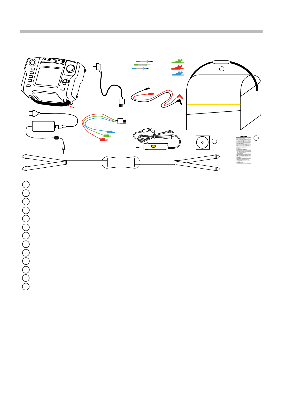
1.1. UNPACKING
1. FIRST START-UP
➀
➂
➇
➁
One C.A 6113.
1
One mains charger with cable for the battery.
2
One tripod cable with mains plug (adapted to the country of sale.
3
➃
➄
➆
➉
➅
12
11
13
➈
One measuring cable, 3 safety leads.
4
Three probe tips (red, blue, and green).
5
Three alligator clips (red, blue, and green).
6
Two elbowed-straight safety leads (red and black).
7
One hand strap.
8
One 4-point hands-free strap.
9
One remote probe.
10
One carrying bag.
11
One user manuals on CD-ROM (1 file per language).
12
One multilingual safety sheet.
13
4

< 264 Vac
50 / 60 Hz
1.2. CHARGING THE BATTERY
Before the first use, start by fully charging the battery. The charging must be done between 10 and 35°C.
> 90 Vac
Battery
loading...
The indicator of the
device lights.
Battery charging connector of the device.
Loading
Charging time:
approximately 6h
After prolonged storage, the battery may be fully discharged. In this case, the first charge may take longer and the indicator on
the device flashes for the first few minutes.
completed.
The indicator goes
off.
Set the switch to OFF, but charging is possible when the device is not off,
1.3. CARRYING THE DEVICE
The 4-point hands-free strap will let you use the device while leaving
your hands free. Snap the four fasteners of the strap onto the four
lugs on the device.
Pass the strap around your neck.
Adjust the length of the strap, then the tilt of the device.
5
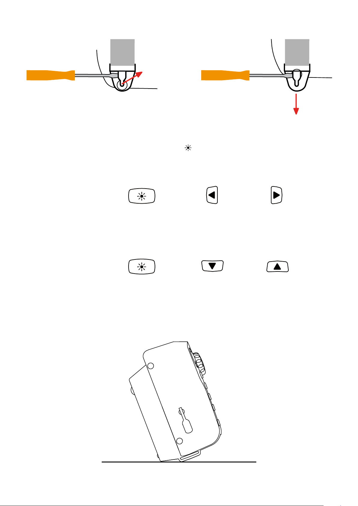
To withdraw the strap, slide a flat screwdriver under the tab of the fastener to lift it, then slide the fastener down.
1.4. CONTRAST AND BRIGHTNESS OF THE DISPLAY
To adjust the contrast and the brightness of the display, press the key and one of the arrow keys simultaneously.
Display contrast
sustained
press
Display brightness
sustained
press
1.5. USE ON A DESKTOP
For use on a desktop, have the device rest on the fasteners of the hand strap and on the housing.
This lets the display unit be read directly.
+
+
or
or
6

1.6. CHOICE OF LANGUAGE
SET-UP
Before using the device, first choose the language in which you want the device to display messages.
Set the switch to SET-UP.
SET UP
Use the directional keypad to select the languages icon:
OK
OFF
OK
Press the OK key to validate your
choice.
Select your language, from among those proposed, using the keys and validate by pressing the OK key again.
7

2. PRESENTATION OF THE DEVICE
TEST
TEST button to start
the measurements.
Four function
keys.
Connection terminals.
SET UP
OFF
OK
Switch for selection
of the measurement
function or SETUP.
Indicator light.
Stud for fixing on
the 4-point handsfree strap.
Help key.
Backlight lighting and adjustment key (contrast and brightness).
Battery charging
connector.
Directional keypad:
four navigation keys
and one validation
key.
Fasteners for the hand
strap, also used to tilt
the device.
Battery
loading...
8

2.1. FUNCTIONS OF THE DEVICE
The C.A 6113 installation tester is a portable measuring device with a monochrome graphic display. It is powered by a rechargeable battery with a built-in charger and external power supply unit.
This device is intended to check the safety of electrical installations. It can be used to test a new installation before it is powered
up, to check an existing installation, whether in operation or not, or to diagnose a malfunction in an installation.
Measurement
functions
Controls one 11-position switch, one five-key navigator, one keypad with four function keys, one context-sensitive
Display 5.7» (115 x 86mm) monochrome graphic LCD display unit, 1/4 VGA (320 x 240 points), with possibility of
voltage
continuity and resistance
insulation resistance
earth resistance (with 3 rods)
loop impedance (Zs)
earth resistance on live circuit (with an auxiliary probe)
selective earth resistance (with an auxiliary probe and an optional current clamp)
line impedance (Zi)
test of residual current devices in ramp mode
test of residual current devices in pulse mode
current (with an optional current clamp)
detection of direction of phase rotation
help key, one backlight key, and one TEST button.
backlighting.
2.2. KEYPAD
The actions of the 4 function keys are indicated on the display unit by adjacent icons. They depend on the context.
The help key can be used in all functions. The help function is context-sensitive: it depends on the function.
The backlight key is also used to adjust the contrast and brightness of the display.
The directional keypad comprises four navigation keys and one validation key.
9

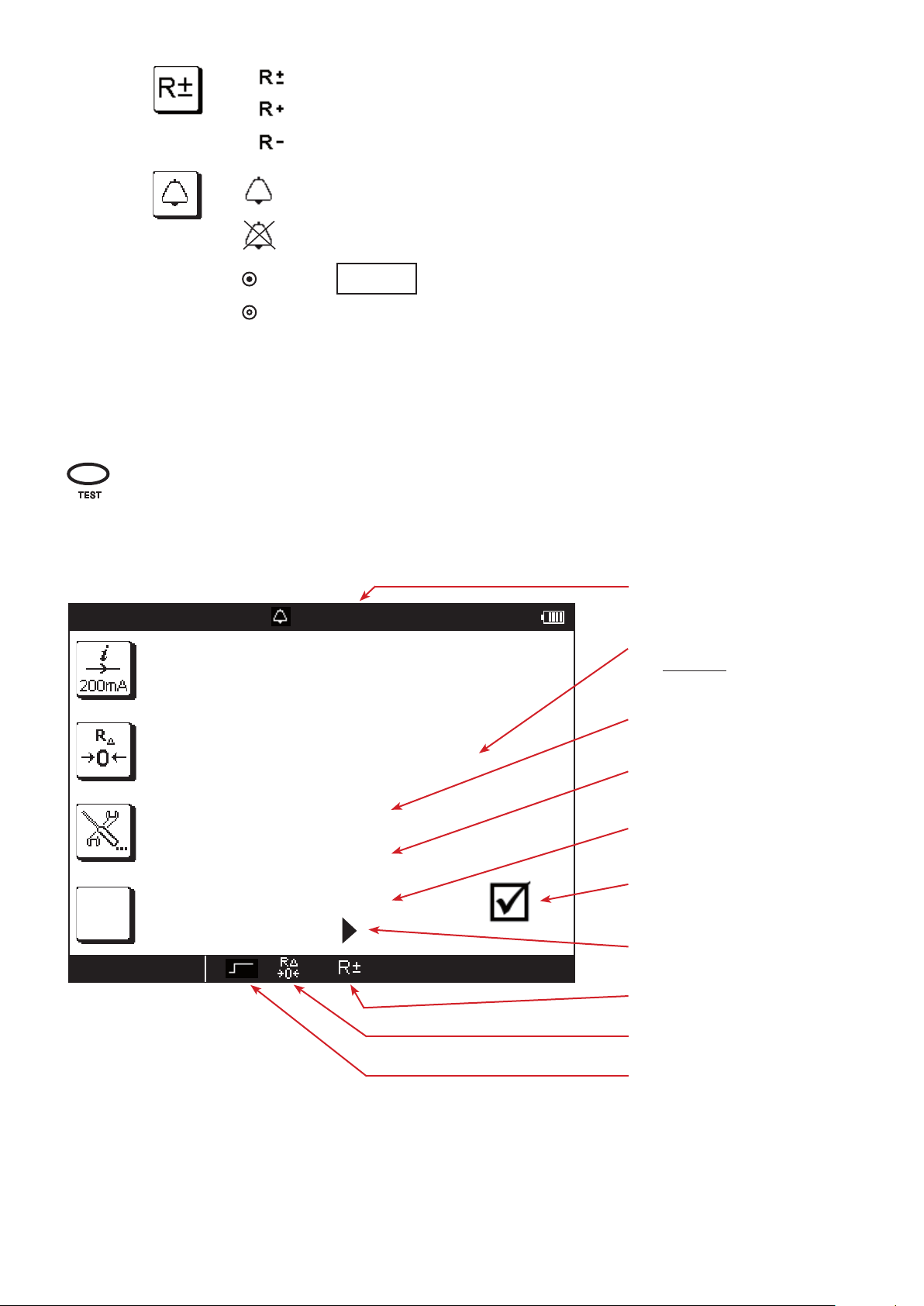
2.3. DISPLAY UNIT
➀
➅
➈
➁
02/09/2014 10:47
6 mA
L-PE 230.3 V
L-N
N-PE
LOOP ZS
➂
50 . 0 Ω 50 . 1 Hz
230.4 V
0.8 V
➃
➄
➆
➇
➉
Top strip
1
Date and time
2
Alarm threshold
3
Frequency measured
4
Condition of the battery
5
Icons representing the functions of the keys
6
11
Position of the phase on the socket outlet
7
Display of measurement results
8
Bottom strip
9
Name of function
10
Information about the measurement in progress
11
10
3. PROCEDURE
3.1. GENERAL
When it leaves the plant, the device is configured so that it can be used without changing the parameters. For most measurements, simply select the measurement function by turning the switch and press the TEST button.
However, you can also parameterize:
the measurements, using the function keys,
or the device itself, using SET-UP.
The device is not designed to operate when the charger is connected. The measurements must be made using battery
power.
3.1.1. CONFIGURATION
When configuring the measurements, you can always choose between:
validating by pressing the OK key,
or exiting without saving by pressing the key.
3.1.2. HELP
In addition to an intuitive interface, the instrument provides complete help in use and analyses and appraisals. Three types of
help function are available:
Help before the measurement can be accessed using the key. It indicates the connections to be made for each function
and important recommendations.
Error messages appear, as soon as the TEST button is pressed, to report connection errors, measurement parameterizing
errors, out-of-range values, defective installations tested, etc.
Help associated with the error messages. Messages containing the icon invite you to look up the help for ways to
eliminate the error found.
3.1.3. REFERENCE POTENTIAL
The user is assumed to be at the reference earth potential. He/she must therefore not be insulated from earth: must not
wear insulating shoes or insulating gloves and must not use a plastic object to press the TEST button.
3.2. VOLTAGE MEASUREMENT
Whichever function is chosen, the device always starts by measuring the voltage present on its terminals.
3.2.1. DESCRIPTION OF THE MEASUREMENT PRINCIPLE
The device separates the alternating voltage from the direct voltage and compares the amplitudes to decide whether the signal
is AC or DC. In the case of an AC signal, the frequency is measured and the device calculates the RMS value of the AC part and
displays it. In the case of a DC signal, the device does not measure its frequency, but calculates its mean value and displays it.
For measurements made at the mains voltage, the device checks that the connection is correct and displays the position of the
phase on the socket outlet. It also checks the presence of a protective conductor on the PE terminal by means of the contact the
user makes with his/her finger by touching the TEST button.
11
L
L
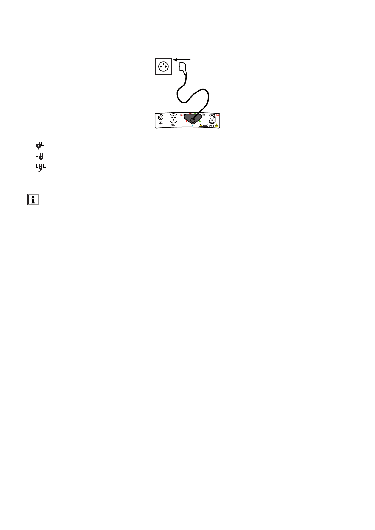
3.2.2. MAKING A MEASUREMENT
Connect the leads to the device to be tested. As soon as the device is powered up, it measures the voltages present on its terminals and displays them, whatever the setting of the switch.
The mains socket outlet of the measuring cable is marked with a white reference spot.
: the phase is on the right-hand contact of the mains plug when the white spot is up.
: the phase is on the left-hand contact of the mains plug when the white spot is up.
: the device cannot determine where the position of the phase, probably because the PE is not connected or the L and
PE conductors are interchanged.
The L symbol is displayed as soon as the voltage is high enough (> UL programmable in SET-UP). The terminal identified
as L is the one that has the highest voltage with respect to PE.
3.2.3. ERROR INDICATION
The only errors reported in voltage measurement are values outside the voltage measurement range. These errors are reported
in clear language on screen.
12

3.3. RESISTANCE AND CONTINUITY MEASUREMENT
3.3.1. DESCRIPTION OF THE MEASUREMENT PRINCIPLE
For continuity measurements, the device generates a DC current of 200 or 12 mA, at the user’s discretion, between the W and
COM terminals. It then measures the voltage present between these two terminals and from it deduces the value of R = V/I.
For resistance measurements (current chosen = kW), the device generates a DC voltage between the W and COM terminals. It
then measures the current between these two terminals and from it deduces the value of R = V/I.
In the case of a measurement at high current (200 mA), at the end of one second, the device reverses the direction of the current
and makes another measurement for one second. The result displayed is the mean of these two measurements. It is possible to
make measurements with either the positive or the negative polarity of the current disabled.
For measurements at low current (12 mA or kW), the polarity is positive only.
3.3.2. MAKING A MEASUREMENT
To comply with standard IEC-61557, the measurements must be made at 200 mA. The reversal of the current serves to compensate for any residual electromotive forces and, more important, to check that the continuity is in fact duplex.
When you make continuity measurements that are not contractual, prefer a current of 12 mA. Even though the results cannot be
regarded as those of a normative test, this significantly increases the life of the device between charges and forestalls untimely
tripping of the installations if there is a connection error.
The permanent mode is used to chain measurements without having to press the TEST button each time.
If the object to be measured is inductive, it is better to switch to pulse mode and make a measurement at positive polarity, then
a measurement at negative polarity, manually, in order to leave time for the measurement to settle.
The alarm, if activated, serves to inform the user, by an audible signal, that the measurement is below threshold, making it unnecessary to look at the display unit to check this point.
Set the switch to W .
Use the leads to connect the device to be tested between the W and COM terminals of the device. The object to be tested must not be live.
SET UP
R
OFF
3.3.3. CONFIGURING THE MEASUREMENT
Before starting the measurement, you can configure it by modifying the parameters displayed:
Choice of measurement current: kW, 12 mA or 200 mA.
The high current (200 mA) can be used only to measure low resistances, up to 40 W.
The low current (12 mA) is used to make measurements up to 400 W.
The choice kW is used to make resistance measurements up to 400 kW.
To correct for the resistance of the measurement leads (leads and probe tips or alligator clips), for measurements
at 12 and 200 mA (see §3.13).
Pressing the TEST button starts only one measurement (pulse mode).
Pressing the TEST button starts the continuous measurement (permanent mode). To
stop it, you must press the TEST button again.
13
Automatic reversal of polarity for a measurement at 200 mA.
TEST
..\..
k Ω
Ω
Measurement at positive polarity only.
Measurement at negative polarity only.
To activate the alarm.
To deactivate the alarm.
002.00
Once the parameters have been defined, you can start the measurement.
If you selected the pulse mode, press the TEST button once and the measurement stops automatically when it is over.
If you selected the permanent mode, press the TEST button once to start the measurement and a second time to
stop it.
3.3.4. READING OF THE RESULT
In the case of a 200 mA current:
02/10/2014 10:47
2.00 Ω - - .- Hz
To set the alarm threshold (see §3.14). The default threshold is 2W.
Value of the alarm threshold.
Measurement result:
(R+) + (R-)
R =
2
Measurement current.
1 %
1 %
CONTINUITY
0 . 8 3 Ω
I 2 0 7 . 4 m A
R + 0 . 5 9 Ω
R - 1 . 0 8 Ω
Measurement with a positive current (R+).
Measurement with a negative current (R-).
Case where the measurement is
below the alarm threshold.
Use the key to see the rest of the
measurement display.
Measurement with reversal of polarity.
Compensation for the resistance of
the measurement leads is activated.
Permanent mode.
14

..\..
To see the next display page.
02/10/2014 10:47
2.00 Ω - - .- Hz
U Ω 0 . 0 V
1 %
CONTINUITY
In the case of a 12 mA current, there is no current reversal.
../..
External voltage present on the
terminals just before the start of the
measurement.
Use the key to return to the previous display page.
02/10/2014 10:47
I 1 2 . 3 m A
1 %
CONTINUITY
2.00 Ω - - .- Hz
1 8 . 4 Ω
Value of the alarm threshold.
Measurement result.
Current measurement.
Case where the measurement is
above the alarm threshold.
Use the key to see the rest of the
measurement display.
The polarity of the current is positive.
Compensation for the resistance of
the measurement leads is activated.
Pulse mode.
15

In the case of a resistance measurement (kW), there is no current reversal and no compensation for the measurement leads.
..\..
02/10/2014 10:47
1 %
RESISTANCE
2.00 kΩ - - .- Hz
1 . 5 8 k Ω
Value of the alarm threshold.
Measurement result.
Case where the measurement is
below the alarm threshold.
Use the key to see the rest of the
measurement display.
Permanent mode.
3.3.5. ERROR INDICATION
The commonest error in the case of a continuity measurement is the presence of a voltage on the terminals. An error message is
displayed if a voltage greater than 0.5 VRMS is detected and you press the TEST button.
In this case, the continuity measurement is not enabled. Eliminate the cause of the interference voltage and start the measurement over.
Another possible error is measurement of an overly inductive load that prevents the measurement current from stabilizing. In this
case, start the measurement in permanent mode with only one polarity and wait for the measurement to stabilize.
For help with connections or any other information, use the help function.
16
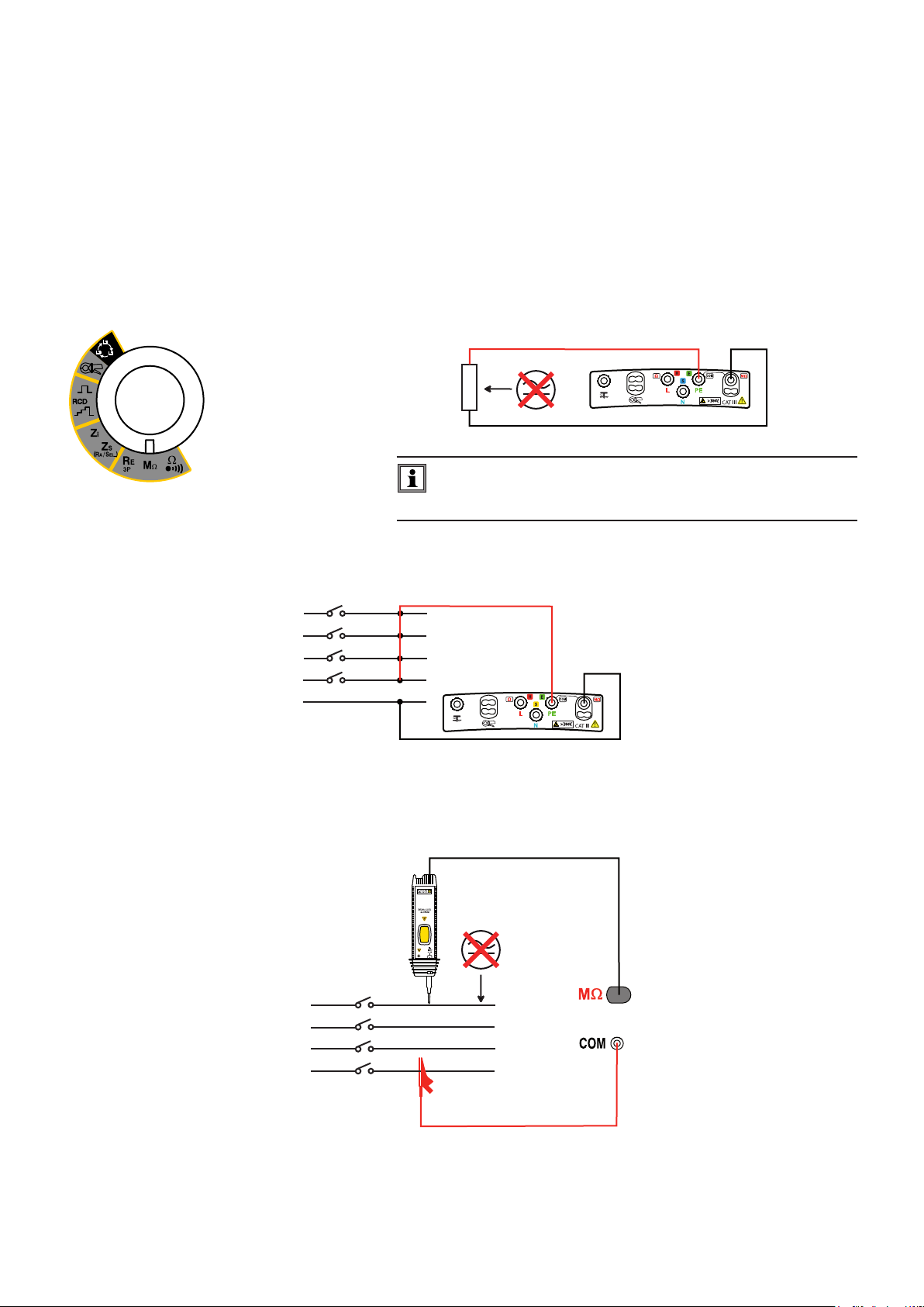
3.4. INSULATION RESISTANCE MEASUREMENT
3.4.1. DESCRIPTION OF THE MEASUREMENT PRINCIPLE
The device generates a DC test voltage between the COM and MW terminals. The value of this voltage depends on the resistance
to be measured: it is greater than or equal to UN when R is greater than or equal to RN = UN /1 mA, and less otherwise. The device
measures the voltage and current present between the two terminals and from them deduces the value of R = V / I.
The COM terminal is the voltage reference point. The MW terminal therefore provides a negative voltage.
3.4.2. MAKING A MEASUREMENT
The alarm, if activated, serves to inform the user, by an audible signal, that the measurement is below threshold, making it unnecessary to look at the display unit to check this point.
Set the switch to MW.
Use the leads to connect the device to be tested between the COM and MW
terminals of the device. The object to be tested must not be live.
SET UP
R
OFF
To avoid leakage during the insulation measurement, which would
throw off the measurement, do not use the measuring cable when
you make this type of measurement, but two simple leads.
Generally, an insulation measurement on an installation is made between the interconnected phase(s) and neutral, on the one
hand, and earth, on the other.
L1
L2
L3
N
PE
If the insulation is not sufficient, you must then make the measurement between each of the pairs to locate the fault.
The remoted TEST button of the optional remote control probe makes it easier to trigger the measurement. To use the remote
control probe, refer to its user’s manual.
C.A 6113/16/17
with
Operation only
L1
L2
L3
PE
17
TEST
..\..
M Ω
Ω
3.4.3. CONFIGURING THE MEASUREMENT
Before starting the measurement, you can configure it by modifying the parameters displayed:
To choose the nominal test voltage UN: 50, 100, 250, 500 or 1000 V.
To activate the alarm.
To deactivate the alarm.
k
Once the parameters have been defined, you can start the measurement.
Keep the TEST button pressed until the measurement is stable. The measurement stops when the TEST button
is released.
Before disconnecting the leads or starting another measurement, wait a few seconds for the device tested to be discharged
(when the symbol disappears from the display unit).
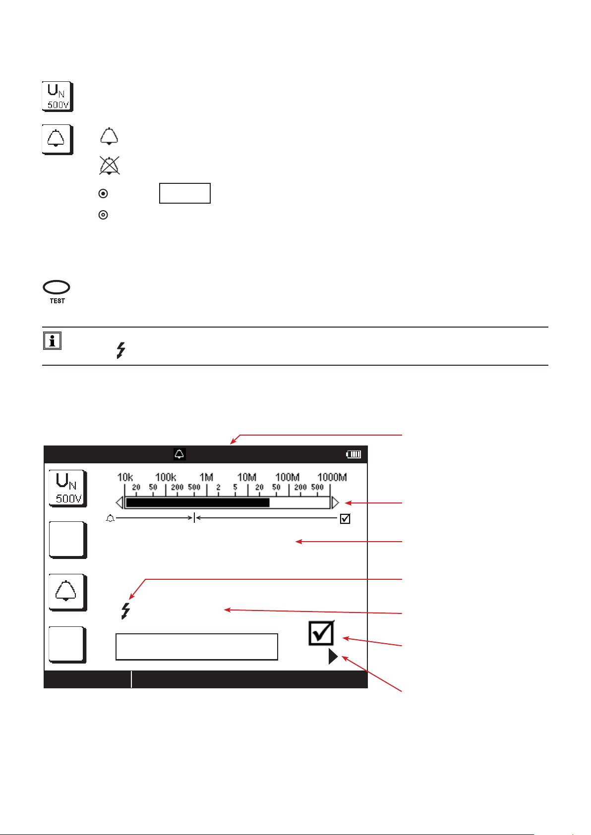
3.4.4. READING OF THE RESULT
02/11/2014 10:47
0500.0
500 kΩ - - .- Hz
To set the alarm threshold (see §3.14). As default, the threshold is set to
R (kW) = UN / 1 mA.
Value of the alarm threshold.
2 %
INSULATION
3 1 . 0 6 M Ω
7 s
Press TEST until the measurement
is stable
The bargraph provides a rapid quantitative indication of the insulation.
Measurement result.
The test voltage UN is present and
dangerous.
Duration of the measurement.
Case where the measurement is
above the alarm threshold.
Use the key to see the rest of the
measurement display.
18

To see the next display page.
02/11/2014 10:47
U M Ω 0 . 0 V
Press TEST until the measurement
2 %
INSULATION
3.4.5. ERROR INDICATION
The commonest error in the case of an insulation measurement is the presence of a voltage on the terminals. If it is greater than
50 V, the insulation measurement is not enabled. Eliminate the voltage and start the measurement over.
is stable
500 kΩ - - .- Hz
../..
External voltage present on the
terminals just before the start of the
measurement.
Use the key to return to the previous display page.
The measurement may be unstable, probably because of an overly capacitive load or an insulation fault. In this case, read the
measurement on the bargraph.
For help with connections or any other information, use the help function.
19

3.5. 3P EARTH RESISTANCE MEASUREMENT
This function is the only one that can measure an earth resistance when the electrical installation to be tested is not live (new
installation, for example). It uses two additional rods, with the third rod being constituted by the earth electrode to be tested
(whence the name “3P”).
It can be used on an existing electrical installation, but the power must be cut off (main RCD). In all cases (new or existing installation), the earthing strip of the installation must be open during the measurement.
It is possible to make a rapid measurement and measure only RE or else to make a more detailed measurement by also measuring the resistances of the rods.
3.5.1. DESCRIPTION OF THE MEASUREMENT PRINCIPLE
The device generates between the H and E terminals a square wave at a frequency of 128 Hz and an amplitude of 35 V. It measures the resulting current, IHE , along with the voltage present between the S and E terminals, USE. It then calculates the value of
RE = USE/IHE.
To measure the resistances of the RS and RH rods, the device internally reverses the E and S terminals and makes a measurement.
It then does likewise with the E and H terminals.
3.5.2. MAKING A MEASUREMENT
There are several measurement methods. We recommend the «62%» method.
Set the switch to RE 3P.
Plant the H and S rods in line with the earth electrode. The distance between the S rod
and the earth electrode must be approximately 62% of the distance between the H rod
and the earth electrode.
SET UP
In order to avoid electromagnetic interference, we recommend paying out the full length of
the cables, placing them as far apart as possible, and not making loops.
earth
OFF
H
S
62% d
d
strap
Connect the cables to the H and S terminals. Power down the installation and disconnect the earth strap. Then connect the E
terminal to the earth electrode to be checked.
The alarm, if activated, serves to inform the user, by an audible signal, that the measurement is above threshold, making it unnecessary to look at the display unit to check this point.
3.5.3. CONFIGURING THE MEASUREMENT
Before starting the measurement, you can configure it by modifying the parameters displayed:
Choice of type of measurement: rapid, to measure RE only (icon crossed out), or detailed, to measure also rod
resistances RS and RH. This last case is useful if the ground is dry, making the resistance of the rods high.
To compensate for the resistance of the lead connected to the E terminal, for measurements of low values (see §3.13).
20

k Ω
Ω
To activate the alarm.
..\..
TEST
To deactivate the alarm.
050.00
If the measurement must be made in a damp environment, remember to change the value of maximum contact voltage
UL in Setup (see §5) and set it to 25 V.
Press the TEST button to start the measurement. The measurement stops automatically.
This symbol invites you to wait while the measurement is in progress.
Do not forget to reconnect the earth strap at the end of the measurement before powering the installation back up.
3.5.4. READING OF THE RESULT
In the case of a detailed measurement:
02/12/2014 10:47
50.0 Ω 50.1 Hz
To set the alarm threshold (see §3.14). As default, the threshold is set to 50W.
3 %
EARTH 3P
R E 3 2 . 0 8 Ω
R s 1 . 5 8 k Ω
R h 1 . 3 2 k Ω
Value of the alarm threshold.
Measurement result.
Resistance of the S rod.
Resistance of the H rod.
Case where the measurement is
below the alarm threshold.
The key is used to see the voltages
before the beginning of the test.
Compensation for the resistance of
the measurement leads is activated.
21

H
d
S
3.5.5. VALIDATION OF THE MEASUREMENT
To validate your measurement, move the S rod towards the H rod by 10% of d and make another measurement. Then move the
S rod, again by 10% of d, but towards the earth electrode.
H
S
52% d
62% d
72% d
d
The 3 measurement results must be the same to within a few percent. If this is the case, the measurement is valid. If not, it is
because the S rod is in the zone of influence of the earth electrode.
If the resistivity of the ground is homogeneous, it is necessary to increase distance d and repeat the measurements. If the resistivity of the ground is inhomogeneous, the measurement point must be moved either towards the H rod or towards the earth
terminal until the measurement is valid.
3.5.6. POSITIONING OF THE AUXILIARY RODS
To make sure that your earth measurements are not distorted by interference, we recommend repeating the measurement with
the auxiliary rods placed at a different distance and in another direction (for example rotated 90° from the first alignment).
2
S
H
S
E
d1
If you find the same values, your measurement is reliable. If the measured values are substantially different, it is probable that
they were influenced by earth currents or a groundwater artery. It may be useful to drive the rods deeper.
If the in-line configuration is not possible, you can plant the rods in a triangle. To validate the measurement, move the S rod on
either side of the line HE.
S
H
E
Avoid routing the connecting cables of the earth rods near or parallel to other cables (transmission or power supply), metal pipes,
rails, or fences, this in order to avoid the risk of cross-talk with the measurement current.
22

3.5.7. ERROR INDICATION
The commonest errors in the case of an earth measurement are the presence of an interference voltage or rod resistances that
are too high.
If the device detects:
a rod resistance greater than 15 kW,
a voltage greater than 25 V on H or on S when the TEST button is pressed.
In these two cases, the earth measurement is not enabled. Move the rods and start the measurement over.
To reduce the resistance of the rods RH (RS), you can add one or more rods, two metres apart, in the H (S) branch of the circuit.
You can also drive them deeper and pack the earth around them, or wet it with a little water.
For help with connections or any other information, use the help function.
23

3.6. LOOP IMPEDANCE MEASUREMENT (ZS)
R
R
OFF
In a TN or TT type installation, the loop impedance measurement is used to calculate the short-circuit current and to size the
protections of the installation (fuses or RCDs), especially their breaking capacity.
In a TT type installation, the loop impedance measurement makes it easy to determine the earth resistance without planting any
rods and without cutting off power to the installation. The result obtained, ZS, is the loop impedance of the installation between
the L and PE conductors. It is barely greater than the earth resistance.
From this value and the conventional touch voltage limit (UL), it is then possible to choose the rated differential operating current
of the RCD: IDN < UL / ZS.
This measurement cannot be made in an IT type installation because of the high earthing impedance of the supply transformer,
which may even be completely isolated from earth.
3.6.1. DESCRIPTION OF THE MEASUREMENT PRINCIPLE
The device starts by generating pulses having a duration of 300 µs and an amplitude of at most 3.5 A between the L and N terminals. This first measurement is used to determine ZL.
It then applies a low current, 6, 9 or 12 mA at the user’s discretion, between the L and PE terminals. This low current serves to
avoid tripping residual current devices of which the nominal current is greater than or equal to 30 mA. This second measurement
is used to determine ZPE.
The device then calculates loop resistance ZS = Z
= ZL+ZPE , and short-circuit current Ik = U
L-PE
LPE/ZS
.
The value of Ik serves to check the proper sizing of the protections of the installation (fuses or RCDs).
For greater accuracy, it is possible to measure ZS with a high current (TRIP mode), but this measurement may trip the RCD of
the installation.
3.6.2. MAKING A MEASUREMENT
Set the switch to ZS (RA/SEL.).
Connect the measuring cable to the device, then to the socket outlet of the installation to be tested.
SET UP
At the time of connection, the device first checks that the voltages present
on its terminals are correct, then determines the position of the phase (L) and
of the neutral (N) with respect to the protective conductor (PE) and displays
it. If necessary, it then automatically switches the L and N terminals so that
the loop measurement can be made without modifying the connections of
the device.
If possible, first disconnect all loads from the network on which you make the loop
measurement.
It is possible to eliminate this step if you use a measurement current of 6 mA, which
allows a leakage current of up to 9 mA for an installation protected by a 30 mA
residual current device.
Case of a TT installation
L
L
RN
N
PE
Rb
in trip mode, it is not necessary to connect the N terminal.
Ra
RN
RE
Rb
Case of a TN installation
L
L
N
PE
24

k Ω
k A
For a more accurate measurement, you can choose a high current (TRIP mode), but the RCD that protects the installation may trip.
TEST
The alarm, if activated, serves to inform the user, by an audible signal, that the measurement is above threshold, making it unnecessary to look at the display unit to check this point.
The signal can be smoothed to produce a mean of several values. But the measurement then takes longer.
3.6.3. CONFIGURING THE MEASUREMENT
Before starting the measurement, you can configure it by modifying the parameters displayed:
6 mA
Choice of measurement current in non-tripping mode: 6, 9, 12 mA
or TRIP mode to use a high current that will give a more accurate measurement.
To activate or deactivate the smoothing of the signal.
To compensate for the resistance of the measurement leads, for measurements of low values (see
§3.13).
The device proposes choosing the voltage for the Ik calculation from among the following values:
(Ik)
ULN (the measured voltage value),
the voltage of the old standard (for example 220 V),
the voltage of the current standard (for example 230 V).
Depending on the voltage ULN measured, the device proposes the following choices:
if 170<ULN<270 V: ULN, 220 V, or 230 V.
if 90<ULN<150 V: ULN, 110 V or 127 V.
if 300<ULN<500 V: ULN, 380 V or 400 V.
To deactivate the alarm.
Z-R
To activate the alarm on Z
(in TRIP mode) or on R
LPE
(in non-tripping mode).
LPE
Ω
Ik
Press the TEST button to start the measurement. The measurement stops automatically.
When the TEST button is pressed, the device checks that the contact voltage is less than UL. If not, it does not
make the loop impedance measurement.
This symbol invites you to wait while the measurement is in progress.
To activate the alarm on Ik.
050.00
010.00
A
To set the alarm threshold (see §3.14). As default,
the threshold is set to 50 W.
To set the alarm threshold (see §3.14). As default,
the threshold is set to 10 kA.
25
 Loading...