

Page 1
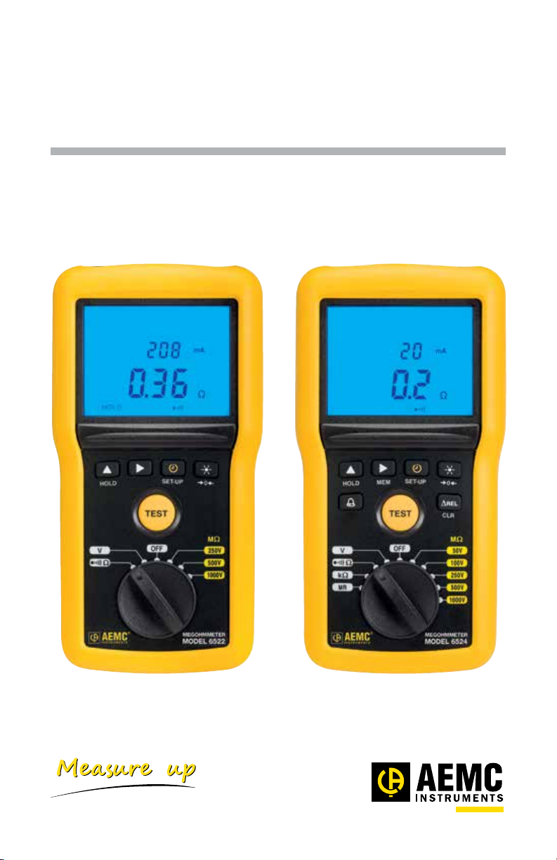
Megohmmeters
Model 6522 & 6524
User Manual
ENGLISH
www.aemc.com
®
CHAUVIN ARNOUX GROUP
Page 2

Statement of Compliance
Chauvin Arnoux®, Inc. d.b.a. AEMC® Instruments
certifies that this instrument has been calibrated using
standards and instruments traceable to international
standards.
We guarantee that at the time of shipping your
instrument has met its published specifications.
An NIST traceable certificate may be requested at
the time of purchase, or obtained by returning the
instrument to our repair and calibration facility, for a
nominal charge.
The recommended calibration interval for this
instrument is 12 months and begins on the date of
receipt by the customer. For recalibration, please
use our calibration services. Refer to our repair and
calibration section at www.aemc.com.
Serial #: ________________________________
Catalog #: 2155.51 / 2155.52
Model #: 6522 / 6524
Please fill in the appropriate date as indicated:
Date Received: _________________________________
Date Calibration Due:
_______________________
Chauvin Arnoux®, Inc.
d.b.a AEMC® Instruments
www.aemc.com
Page 3

Copyright © Chauvin Arnoux®, Inc. d.b.a. AEMC® Instruments. All rights reserved.
No part of this documentation may be reproduced in any form or by any means (including electronic storage and retrieval
or translation into any other language) without prior agreement and written consent from Chauvin Arnoux®, Inc., as
governed by United States and International copyright laws.
Chauvin Arnoux®, Inc. d.b.a. AEMC® Instruments
15 Faraday Drive • Dover, NH 03820 USA
Tel: (800) 945-2362 or (603) 749-6434 • Fax: (603) 742-2346
This documentation is provided “as is,” without warranty of any kind, express, implied, or otherwise. Chauvin Arnoux®,
Inc. has made every reasonable eort to ensure that this documentation is accurate; but does not warrant the accuracy or
completeness of the text, graphics, or other information contained in this documentation. Chauvin Arnoux®, Inc. shall not
be liable for any damages, special, indirect, incidental, or inconsequential; including (but not limited to) physical, emotional
or monetary damages due to lost revenues or lost prots that may result from the use of this documentation, whether or
not the user of the documentation has been advised of the possibility of such damages.
Chauvin Arnoux®, Inc and AEMC® are registered trademarks of AEMC® Instruments.
Page 4
Thank you for purchasing the Megohmmeter Model 6522 or 6524.
For best results from your instrument:
■ Read these operating instructions carefully
■ Comply with the precautions for use
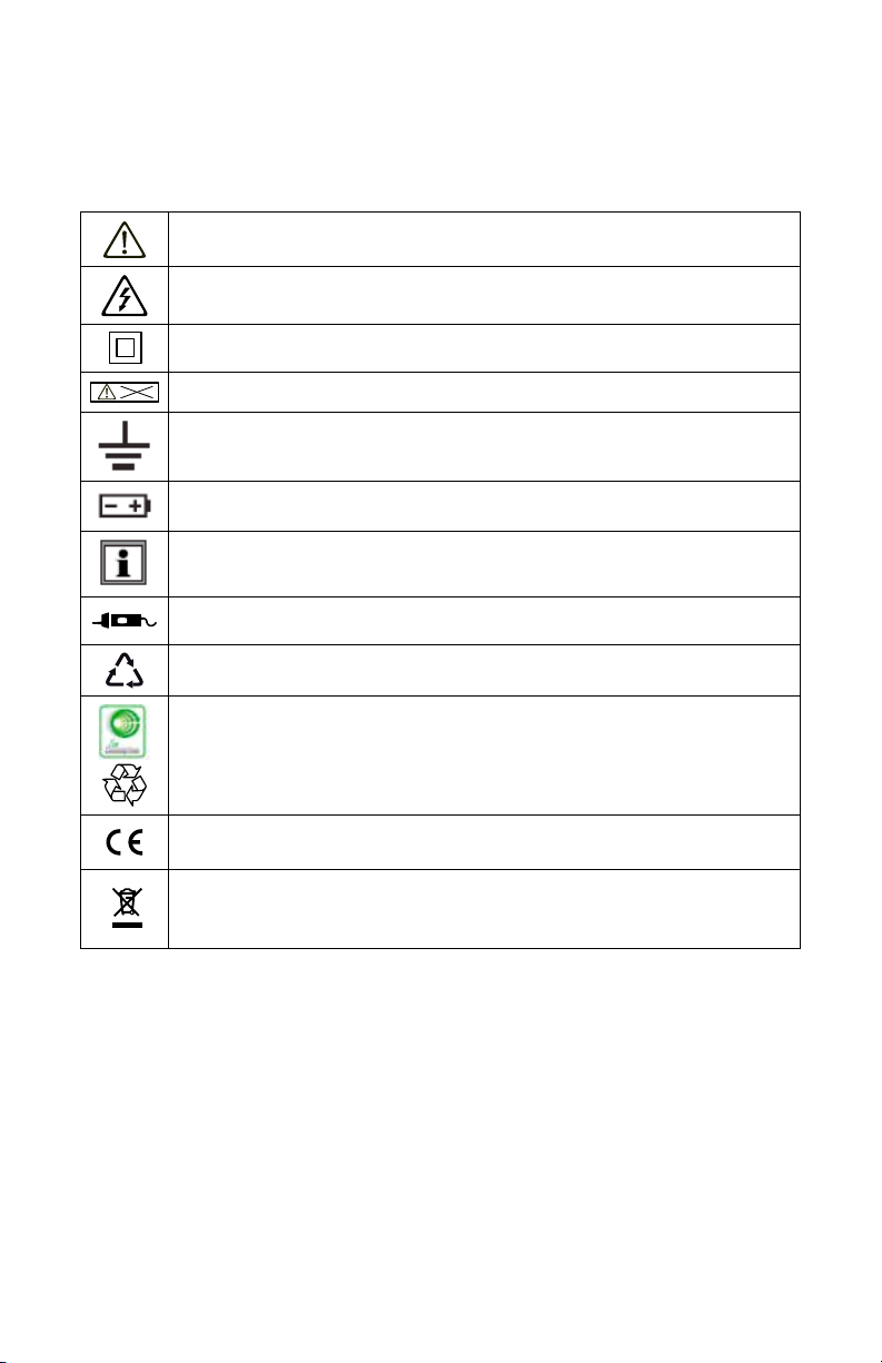
WARNING, risk of DANGER! The operator must refer to these
instructions whenever this danger symbol appears
WARNING, risk of electric shock. The voltage applied to parts
marked with this symbol may be hazardous
Equipment is protected by double insulation
> 700V
The voltage on the terminals must not exceed 700V
Ground/Earth
Battery
Information or useful tip
Remote test probe
The product is recyclable in accordance with standard ISO14040
This instrument exceeds regulatory requirements with respect to
recycling and reuse
Indicates conformity with European directives, in particular LVD and
EMC
Indicates that, in the European Union, the instrument must undergo
selective disposal in compliance with Directive WEEE 2002/96/EC.
This instrument must not be treated as household waste
Denition of Measurement Categories (CAT)
■ CAT II corresponds to measurements taken on circuits directly connected to
low-voltage installations.
Example: power supply to electro-domestic devices and portable tools.
■ CAT III corresponds to measurements on building installations.
Example: distribution panel, circuit-breakers, machines or xed industrial
devices.
■ CAT IV corresponds to measurements taken at the source of low-voltage
installations.
Example: power feeders and protection devices.
Page 5

PRECAUTIONS FOR USE
This instrument is compliant with safety standard IEC 61010-2-030, and the leads
are compliant with IEC 61010-031, for voltages up to 600V in CAT IV or 1000V in
CAT III.
Failure to observe the following safety instructions may result in electric shock,
re, explosion, and damage to the instrument and installation.
■ Carefully read and understand all precautions for use.
■ Be aware of all electrical hazards when using this instrument.
■ Using this instrument other than as specied may compromise its user
protection features.
■ The safety of any system in which this instrument is incorporated is the
responsibility of the integrator of the system.
■ This instrument can be used on CAT IV installations, for voltages
not exceeding 600V
RMS
with respect to ground or 700V
between terminals.
■ Do not use the instrument on networks whose voltage or category
exceeds those specied in this manual.
■ Observe all environmental conditions of use (see § 3).
■ Except for voltage measurements, take no measurements on
electrically “live” systems.
■ Do not use the instrument if it appears damaged, incomplete, or poorly
closed.
■ Before each use, check the condition of the insulation on the leads,
housing, and accessories. Any part on which the insulation is
deteriorated (even partially) must be set aside for repair or scrapping.
■ Using the instrument without its battery compartment cover may result
in electric shock to the user.
■ Before using your instrument, ensure it is completely dry.
■ Use only the leads and accessories supplied. The use of leads (or
other accessories) of a lower voltage rating or category limits the use
of the instrument/leads (or accessories) combination to the lowest
category and service voltage.
■ When handling the leads, test probes, and alligator clips, keep your
ngers behind the physical guards.
■ Before removing the battery compartment cover, ensure all
measurement leads and accessories are disconnected. Replace all
batteries at once. Use alkaline batteries.
■ Use personal protection equipment where appropriate.
■ All troubleshooting and metrological checks must be done by
competent, accredited personnel.
RMS
maximum
Page 6

Table of Contents
1. INTRODUCTION .....................................................................4
1.1 Receiving Your Shipment......................................................................4
1.2 Accessories...........................................................................................5
1.3 Replacement Parts ...............................................................................5
1.4 Description ............................................................................................5
1.4.1 Model 6522 (Front) ...................................................................6
1.4.2 Model 6524 (Front) ...................................................................7
1.5 Back of Instrument ................................................................................8
1.6 Terminals ..............................................................................................9
1.7 Function Buttons ...................................................................................9
1.8 LCD Display .......................................................................................10
2. OPERATION .......................................................................... 11
2.1 Setting Up the Instrument ...................................................................11
2.1.1 Conguration Settings ...........................................................11
2.1.2 Alarms.....................................................................................12
2.1.2.1 Activating/Deactivating the Alarm Function ....................12
2.1.2.2 Setting an Alarm Threshold ............................................13
2.1.2.3 Viewing Alarms ..............................................................14
2.1.3 ∆REL Function (Model 6524) .................................................15
2.1.4 HOLD Function.......................................................................16
2.1.5 Backlighting ............................................................................16
2.1.6 Standby Mode ........................................................................16
2.2 Taking Measurements .........................................................................17
2.2.1 Voltage Measurement.............................................................17
2.2.2 Insulation Measurement .........................................................18
2.2.2.1 TEST Button Operation ..................................................20
2.2.2.2 Timed Tests ...................................................................21
2.2.2.3 Remote Control Probe (Optional) ..................................22
2.2.3 Continuity Measurement.........................................................23
2.2.3.1 Lead Compensation .......................................................23
2.2.3.2 Continuity Measuring .....................................................24
2.2.4 Resistance Measurement (Model 6524).................................25
2.3 Recording Data (Model 6524).............................................................26
2.3.1 Recording a Measurement .....................................................26
2.3.2 Viewing Stored Recordings ....................................................27
2
Megohmmeter Model 6522/6524
Page 7

2.3.3 Deleting Recordings ...............................................................28
2.3.3.1 Deleting a Single Recording ..........................................28
2.3.3.2 Deleting All Recordings ..................................................28
3. SPECIFICATIONS ................................................................. 29
3.1 General Reference Conditions ...........................................................29
3.2 Electrical Specications ......................................................................29
3.2.1 Voltage Measurement.............................................................29
3.2.2 Frequency Measurement........................................................30
3.2.3 Insulation Measurement .........................................................30
3.2.4 Continuity Measurement.........................................................32
3.2.5 Resistance Measurement (Model 6524).................................32
3.2.6 Timer.......................................................................................32
3.2.7 Storage Memory (Model 6524) ...............................................33
3.3 Operating Environment .......................................................................33
3.3.1 Voltage Measurement.............................................................33
3.3.2 Insulation Measurement .........................................................34
3.3.3 Resistance and Continuity Measurement ...............................35
3.3.4 Intrinsic Uncertainty and Operating Uncertainty .....................36
3.4 Power Supply......................................................................................36
3.5 Environmental Conditions ...................................................................36
3.6 Mechanical Specications .................................................................37
3.7 Safety Standards ................................................................................37
4. MAINTENANCE & TROUBLESHOOTING ...............................38
4.1 Maintenance .......................................................................................38
4.1.1 Cleaning .................................................................................38
4.1.2 Replacing the Batteries ..........................................................38
4.2 Troubleshooting ..................................................................................40
4.2.1 Errors ......................................................................................40
4.2.1.1 Voltage present before an insulation measurement.......40
4.2.1.2 Range exceeded during an insulation measurement.....40
4.2.1.3 Voltage during continuity/resistance/measurement .......41
4.2.1.4 Memory full (Model 6524) ..............................................41
4.2.2 Resetting the Instrument ........................................................41
4.3 Repair and Calibration ........................................................................42
4.4 Technical and Sales Assistance ..........................................................42
4.5 Limited Warranty .................................................................................43
4.6 Warranty Repairs ................................................................................43
Megohmmeter Model 6522/6524
3
Page 8

1. INTRODUCTION
1.1 Receiving Your Shipment
Upon receiving your megohmmeter product package, ensure the contents are
consistent with the packing list. Notify your distributor of any missing items. If
the equipment appears to be damaged, le a claim immediately with the carrier
and notify your distributor at once, providing a detailed description. Save the
damaged packing container to substantiate your claim.
Ordering Information:
Megohmmeter Model 6522.............................................................. Cat. #2155.51
Megohmmeter Model 6524.............................................................. Cat. #2155.52
Shipping Contents:
One of the following:
Megohmmeter Model 6522
Megohmmeter Model 6524
Both models also include 6 AA batteries and a user manual.
4
or
Soft Carrying Case
Two 1.5m test leads (red/black), two alligator clips
(red/black), 1 test probe (black)
Megohmmeter Model 6522/6524
Page 9
1.2 Accessories
Megohmmeter Test Probe ................................................................ Cat. #2155.75
Case - Field Case (Waterproof) ........................................................ Cat. #2118.98
Case - Hands Free Carrying Case ................................................... Cat. #2118.99
Continuity Pole .................................................................................Cat. #2138.54
Probe - Set of 2, Color-coded (Red/Black) Grip Probes ................... Cat. #2152.26
1.3 Replacement Parts
Lead - Set of 2, Color-coded 5 ft (Red/Black) Silicone Leads, Test Probes &
Alligator Clips {Rated 1000V CAT IV} ............................................... Cat. #2152.05
For accessories and replacement parts, visit our store at www.aemc.com.
1.4 Description
The Megohmmeters Models 6522 and 6524 are portable measuring instruments
with digital displays. They are powered by batteries. These instruments can
check the safety of electrical installations. For example, they can be used to test
new installations before they are powered up, check an existing installation in a
power-o condition, or troubleshoot an installation.
Features Include:
Model 6522 Model 6524
Insulation test voltages 250, 500, and
1000V
PI and DAR ratios calculation
Continuity measurement
Resistance measurement
Programmable alarms
Frequency measurement
Storage of the measurements
Megohmmeter Model 6522/6524
50, 100, 250, 500, and
1000V
5
Page 10
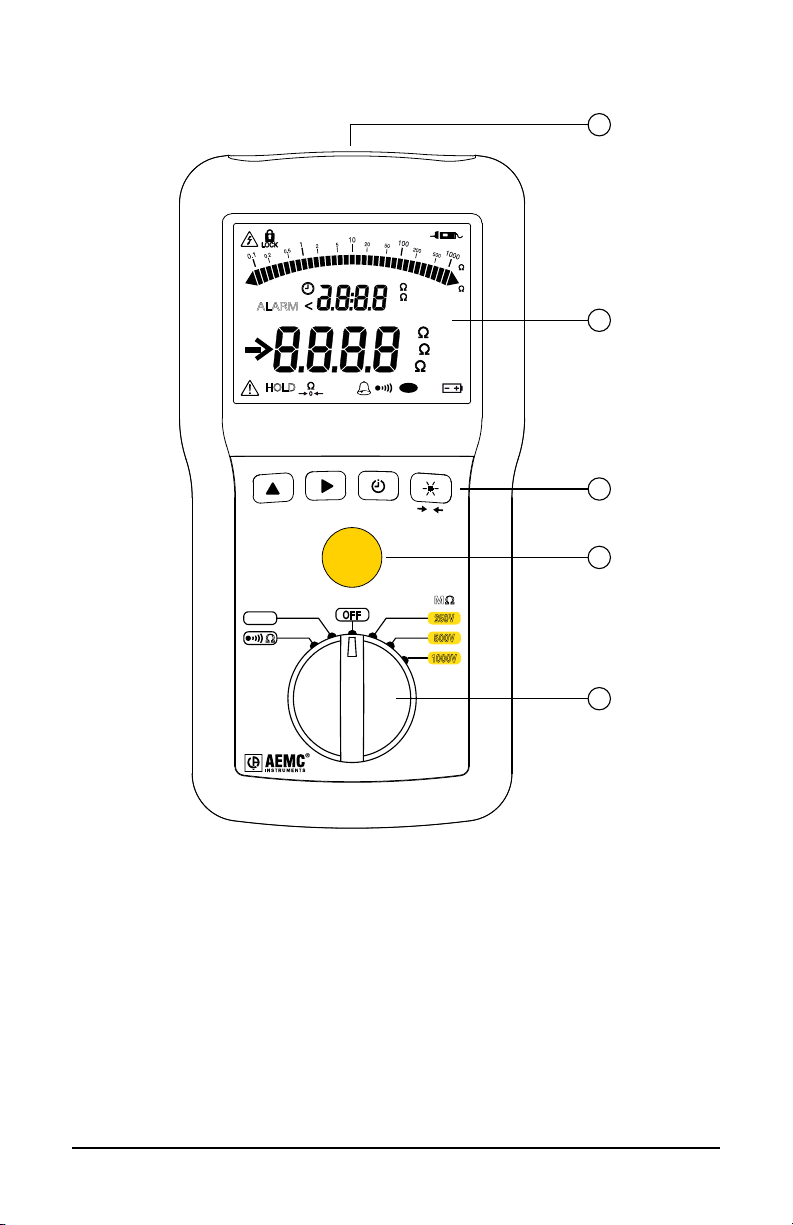
1.4.1 Model 6522 (Front)
<
ALARM
HOLD
G VHz
M mAµA
G
M
k
P
1
M
%
G
2
DC
AC
V
HOLD
SET-UP
0
TEST
MΩ
V
Ω
OFF
MEGOHMMETER
MODEL 6522
250V
500V
1000V
Figure 1
1. Input terminals
2. Blue backlit LCD
3. Four function buttons (see § 1.7)
4. TEST button to start insulation measurements (see § 2.2.2.1)
3
4
5
5. Six-position rotary switch to choose the function or to turn the instrument
OFF
6
Megohmmeter Model 6522/6524
Page 11
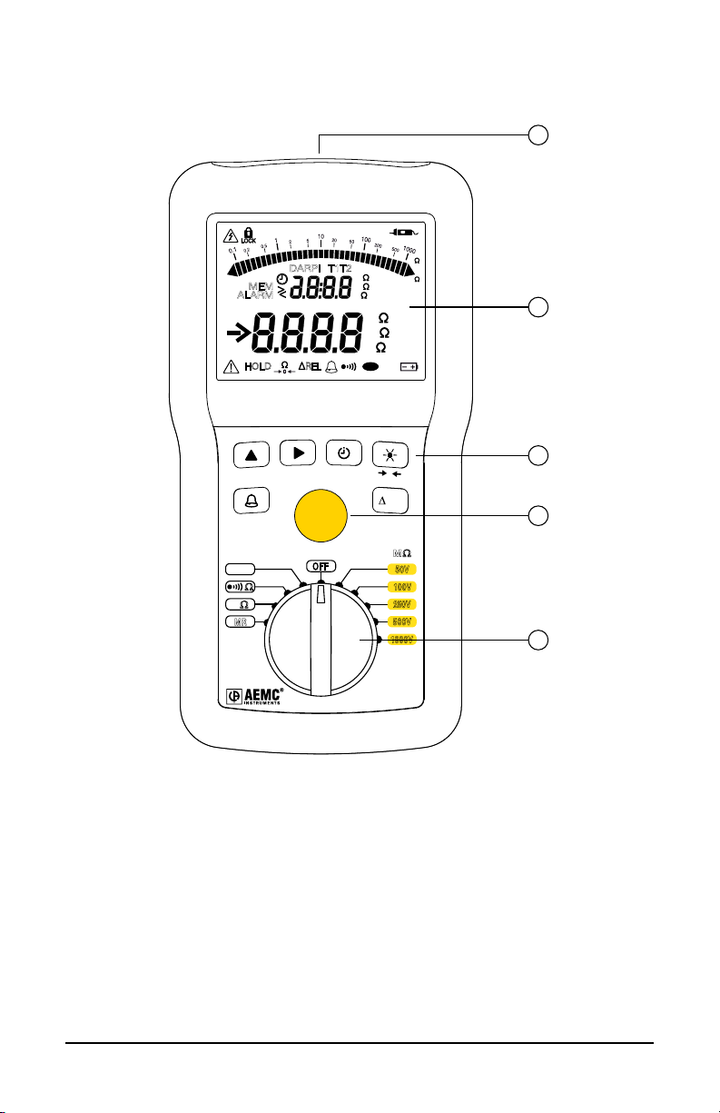
1.4.2 Model 6524 (Front)
1
ALARM
HOLD
HOLD
V
Ω
Ω
k
MR
MEM
>
<
DARPI
MEM
REL
TEST
OFF
T1T2
SET-UP
%
G VHz
M mAµA
k
G
M
DC
AC
V
k
P
0
REL
CLR
MΩ
50V
100V
250V
500V
1000V
MEGOHMMETER
MODEL 6524
M
G
2
3
4
5
Figure 2
1. Input terminals
2. Blue backlit LCD
3. Six function buttons (see § 1.7)
4. TEST button to start insulation measurements (see § 2.2.2.1)
5. Ten-position rotary switch to choose the function or to turn the instrument
OFF
Megohmmeter Model 6522/6524
7
Page 12
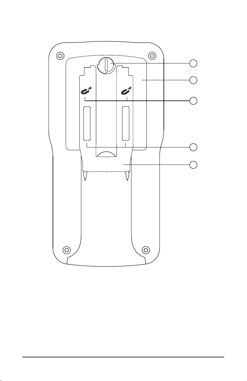
1.5 Back of Instrument
1
2
3
4
5
Figure 3
1. Captive quarter-turn screw
2. Battery compartment cover
3. Mounting magnets, molded into instrument case (Model 6524)
4. Non-skid pads
5. Stand
8
Megohmmeter Model 6522/6524
Page 13
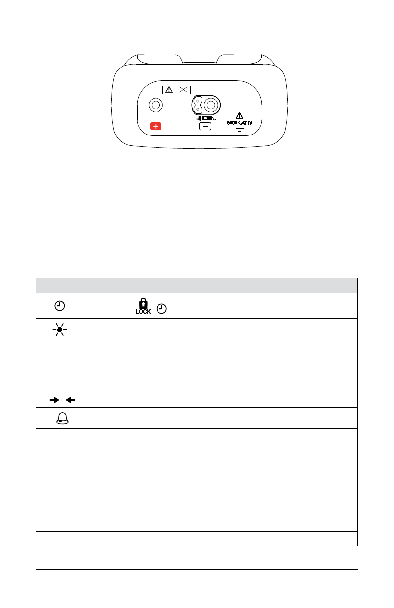
1.6 Terminals
0
> 700V
600V CAT IV
Figure 4
The instrument has one positive ( + ) terminal and one negative ( - ) terminal. The
negative terminal also supports the remote probe accessory (see § 2.2.2.3).
1.7 Function Buttons
In general, each button has two functions. One is marked on the button, and is
enabled via a short press. The second function is marked under the button, and
is enabled by a long (>2 seconds) press.
BUTTON
DESCRIPTION
Selects the , , PI, and DAR functions (§ 2.2.2).
Toggles backlighting ON and OFF (§ 2.1.5).
HOLD
SET-UP
Freezes/unfreezes the displayed measurement on the LCD (§
2.1.4).
Accesses the instrument’s setup parameters and information (§
2.1.1).
Applies lead compensation in continuity testing (§ 2.2.3.1).
(Model 6524) Activates/deactivates alarms (§ 2.1.2).
Modify the display and program the durations of insulation
measurements (§ 2.2.2.2).
Choose the continuity test current (§ 2.2.3).
Program the alarm thresholds on the Model 6524 (§ 2.1.2).
∆Rel
(Model 6524) Displays the dierence between the present
measurement and a stored reference measurement (§ 2.1.3).
MEM (Model 6524) Records measurements (§ 2.3).
CLR (Model 6524) Erase recorded measurements (§ 2.3.3).
Megohmmeter Model 6522/6524
9
Page 14
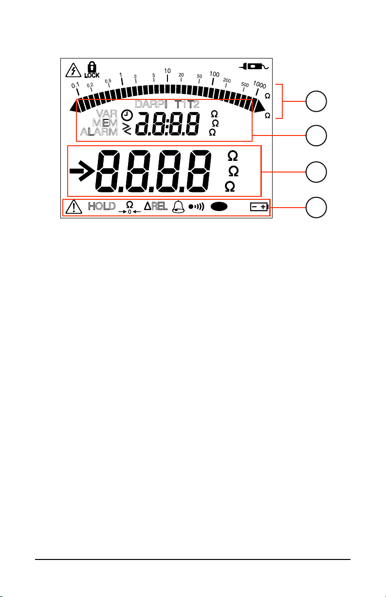
1.8 LCD Display
V
%
nF
µF
DC
AC
M
1
G
2
3
4
VAR
MEM
ALARM
>
<
DARPI
T1T2
G VHz
M mAµA
k nF/ km
G
M
k
HOLD
1. Logarithmic bar graph displays insulation measurements
2. Secondary display area
3. Main display area
4. Icons/indicators
When the measured value is below the minimum, the instrument displays - - - - .
When measuring voltage, if the reading falls outside the range dened by the
positive and negative limits, the instrument displays OL or – OL.
REL
Figure 5
P
10
Megohmmeter Model 6522/6524
Page 15
2. OPERATION
SET-UP
Except when measuring voltage, all measurements must be made on poweredoff systems. Therefore check to ensure there is no voltage on the system under
test before making a non-voltage measurement. When the rotary switch is set
to the voltage or an insulation testing position, the instrument measures and
displays any voltage present at the input terminals prior to the user pressing the
test button.
2.1 Setting Up the Instrument
2.1.1 Configuration Settings
A >2 second press of the SET-UP button enables you to
change conguration settings on the instrument. You can
then use the ▲ and ► buttons to scroll through and modify
> 2s
parameters.
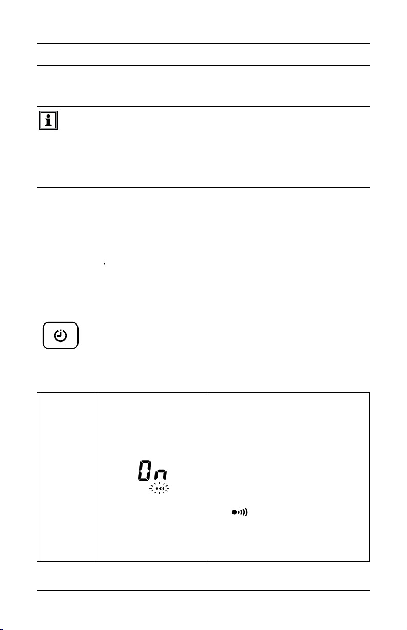
In Set-Up mode, the ▲ button performs the following functions:
1st press
on
Megohmmeter Model 6522/6524
The alarm buzzer is active. To
deactivate it:
1. Press . On will blink to
indicate it is selected.
2. Press to change the
setting to OFF.
3. Press to validate the
change.
The symbol disappears from the
display when you exit Set-Up.
Note that this setting reverts to On
when you turn OFF the instrument.
11
Page 16

2nd press
P
P
on
Automatic switching to standby
mode is activated. To deactivate it:
1. Press to select OFF (the
setting blinks).
2. Press to change the
setting to On.
3. Press to validate the
change.
rd
press
3
on
th
press
4
on
5th press
on
6th press
on
The
display when you exit Set-Up.
Note that this setting reverts to OFF
when you turn OFF the instrument.
Displays the instrument model
number.
Displays the instrument rmware
version.
Displays the instrument hardware
version.
Return to the rst press.
symbol appears on the
2.1.2 Alarms
The instrument includes an alarm function that sounds an audible buzzer when a
dened alarm condition is measured. Alarm features are model-dependent (see
below).
2.1.2.1 Activating/Deactivating the Alarm Function
Model 6522:
The alarm is available in continuity testing mode. Pressing
the TEST button activates the alarm. The
on the LCD, along with the threshold value (2Ω). If the
measurement is below this threshold and the buzzer is active,
the instrument emits an audible signal.
Megohmmeter Model 6522/6524
12
TEST
symbol appears
Page 17

Model 6524:
The alarm is available in insulation, resistance, and continuity
measurement modes. Pressing the
alarm. The
value.
symbol is displayed, along with the threshold
button activates the
ALARM
To turn OFF the alarm buzzer while it is sounding, press the HOLD button. To
deactivate an active alarm function, press the
2.1.2.2 Setting an Alarm Threshold
While
the alarm threshold by pressing the button (except during insulation
measurements). For each testing mode, there are three pre-dened threshold
values:
is displayed indicating the alarm function is active, you can change
■ Continuity: < 2Ω, <1Ω and <0.5Ω
■ Resistance: >50kΩ, >100kΩ and >200kΩ
■ Insulation:
50V : <50kΩ, <100kΩ and <20kΩ
100V : <100kΩ, <200kΩ and <400kΩ
250V : <250kΩ, <500kΩ and <1MΩ
500V : <500kΩ, <1MΩ and <2MΩ
1000V : <1MΩ, <2MΩ and <4MΩ
<
button.
Megohmmeter Model 6522/6524
13
Page 18
In each measurement mode, the third threshold can be replaced by a user-
ALARM
<
M
ALARM
k
M
>
dened value. To do this:
1. Press the ► button while the threshold value is displayed.
2. The > symbol starts blinking; you can change it to < by pressing the
button. This symbol indicates the direction of the alarm threshold: < for a
low threshold and > for a high threshold.
3. To change the threshold setting, press the ► button to navigate to the
rst digit, and then use the button to change its value.
4. Use the ► and buttons to select and change the other digits in the
threshold value, as well as the units of measurement.
5. When nished setting the threshold, press the ► button to validate the
setting.
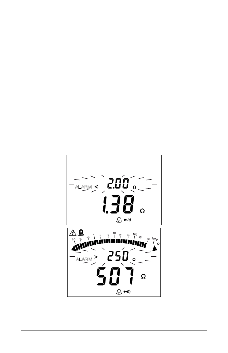
2.1.2.3 Viewing Alarms
When the measurement is below a low alarm threshold or above a high alarm
threshold, the instrument emits a continuous audible signal and the LCD
indicates the threshold crossed:
When checking continuity, this enables you to determine whether or not the
continuity measurement is less than 2Ω simply by listening, without looking at the
display. You can similarly check insulation quality.
14
Megohmmeter Model 6522/6524
Page 19

2.1.3 ∆REL Function (Model 6524)
CLR
M
REL
V
G
For an insulation, resistance, or capacitance measurement,
you can congure the instrument to subtract a reference value
from the measured value and display the dierence.
To activate this function, take a measurement, and then press
REL
If the measured value is less than the stored value, the display becomes
negative.
the ∆REL button. This measurement becomes the reference
(R
ref) and will be stored and subtracted from subsequent
measurement values (R
the LCD while this function is activated.
meas). The ∆REL symbol appears on
You can display the dierence as a percentage of the reference (
by pressing the button until the % sign appears:
%
G
M
REL
For insulation measurements, only the digital display is modified by ∆REL. The
bar graph continues to display the true measured value.
To deactivate the ∆REL function, press the ∆REL button or turn the rotary switch
to another setting.
Megohmmeter Model 6522/6524
15
)
Page 20

2.1.4 HOLD Function
HOLD
0
Pressing the HOLD button freezes the display of the
measurement. This can be done in all functions except the MΩ
settings, or during a timed measurement (
To unfreeze the display, press the HOLD button again.
2.1.5 Backlighting
Pressing the button turns ON backlighting for the LCD.
, DAR, PI).
To switch it OFF, press the
backlighting goes OFF automatically at the end of one
minute.
2.1.6 Standby Mode
After 5 minutes of operation with no user activity, the instrument automatically
switches to standby mode. To restore normal operation, simply press any button.
The instrument returns to the state it was in prior to entering standby mode, with
no loss of information (value of the last measurement, compensation of the leads,
∆Rel, timed mode, alarm, etc.).
Automatic switching to standby mode is disabled during:
■ insulation measurements in
DAR).
■ continuity measurements, for as long as measurements are made.
Automatic switching to standby is disabled via the SET-UP button (see § 2.1.1).
mode and in timed mode ( , PI, or
button again. Otherwise,
16
Megohmmeter Model 6522/6524
Page 21

2.2 Taking Measurements
100V
V
k
Ω
MR
OFF
Ω
250V
500V
1000V
50V
MΩ
2.2.1 Voltage Measurement
To ensure proper and accurate operation of the instrument, we recommend
measuring a known voltage (such as an electrical outlet) before measuring
unknown voltages.
1. Set the switch to V or to one of the MΩ positions.
2. Using the leads, connect the system to be tested to the instrument’s
terminals.
The instrument displays the voltage on the terminals. It detects whether the
voltage is AC or DC; and (for the Model 6524) if it is AC, displays its frequency.
Megohmmeter Model 6522/6524
G VHz
DC
AC
V
17
Page 22

V
DC
AC
G VHz
In the MΩ settings, the symbol indicates that the voltage is too high (>25V)
V
DC
AC
G VHz
and that insulation measurements are prohibited:
If the voltage is >15V, continuity, resistance, and capacitance measurements are
prohibited.
2.2.2 Insulation Measurement
Insulation measurement results can be affected by the impedances of
additional circuits connected in parallel or by transient currents.
Do not start any measurement while the symbol
is displayed.
1. Set the rotary switch to one of the MΩ positions. The test voltage
depends on the voltage of the installation to be tested.
18
Megohmmeter Model 6522/6524
Page 23

100V
V
k
Ω
MR
OFF
Ω
250V
500V
1000V
50V
MΩ
2. Use the leads to connect the system to be tested to the instrument’s
terminals. The system under test must be powered down and
discharged. When testing insulation, the typical connection is negative
(black) lead to conductor and positive (red) lead to ground or the outer
insulation of the device under test.
DC
V
3. (Optional) Press the button to display the current or the elapsed time.
(You can also do this during the measurement.)
4. Press the TEST button and hold it down until the displayed
measurement is stable. Note that if the instrument detects a voltage
greater than 25V in the system under test, pressing the TEST button
has no eect because the test will be prohibited. (An error screen will
appear.)
5. The resistance measurement is displayed on the LCD’s main display
area and on the bar graph. The secondary display area indicates the test
voltage generated by the instrument.
Megohmmeter Model 6522/6524
19
Page 24

M
G V
> 1s
TEST
The symbol indicates that the instrument is generating a hazardous
voltage (>70V).
6. At the end of the measurement, release the TEST button. The
instrument stops generating the test voltage and discharges the device
being tested. The
system under test has fallen below 70V.
NOTE: Do not disconnect the leads and do not start any measure-
ment while the symbol
When you release the TEST button, the measurement results remain displayed
until the next measurement, or the HOLD button is pressed, or the instrument is
turned OFF.
symbol is displayed until the voltage on the
is displayed.
M
2.2.2.1 TEST Button Operation
Pressing the TEST button starts an insulation measurement. In normal mode, the
test voltage is generated for as long as the button is pressed. When the button is
released, the measurement stops.
mode, press the test button once to start the measurement, then press it a
In
second time to stop; there is no need to keep the button pressed. However, if you
do not stop the measurement, it will stop automatically after 15 minutes.
In timed test mode (
measurement. The test will stop automatically at the end of the dened test
duration time.
20
, DAR, or PI) press the TEST button once to start the
Megohmmeter Model 6522/6524
Page 25

2.2.2.2 Timed Tests
PI
T1T2
DARPI
T1T2
The TIMER button activates timed test mode. This button is active only for
insulation measurements.
1st press This locks the TEST button. After you start the
measurement, it continues to run without requiring you to keep the TEST button pressed. The
test will run until you stop it, or when 15 minutes
have passed.
nd
press This activates timed test mode. You can set a test
2
duration between 1 and 39:59 minutes. Use the
and buttons to modify the value displayed.
When the time duration is displayed, press the
button to enter edit mode. When the rst digit
blinks, you can change it using the button.
Press to go to the next digit and to change
it. Then press to validate.
rd
press
3
th
press
4
th
press Exits timed test mode.
5
(Model 6524) This enables the PI function. This
is used to calculate the polarization index (the
ratio of the measurement at 10 minutes to the
measurement at 1 minute).
(Model 6524) This enables the DAR function. This
is used to calculate the dielectric absorption ratio
(the ratio of the measurement at 1 minute to the
measurement at 30 seconds).
When
, DAR, or PI is activated, pressing the TEST button starts the test. The
LCD displays the measurement, along with a “countdown” timer showing the time
remaining in the test. The test automatically stops when the duration end time is
reached and the result is displayed.
DAR
M
M
DAR
Megohmmeter Model 6522/6524
21
Page 26

HOLD
Successive presses on the button display intermediate
TEST
values. These include:
For
:
■ Programmed time, voltage, and current at the end of
the measurement
For PI and DAR:
■ T1 time and the voltage, current, and insulation
resistance at that time
■ T2 time and the voltage, current, and insulation
resistance at that time
Use the following table as a guide for interpreting the results of a DAR or PI test:
DAR PI Condition of insulation
DAR < 1.25 PI < 2 Poor or even dangerous
1.25 ≤ DAR < 1.6 2 ≤ PI < 4 Good
1.6 ≤ DAR 4 ≤ PI Excellent
Press the TEST button to return to voltage measurement.
2.2.2.3 Remote Control Probe (Optional)
The optional remote control probe is used to trigger the measurement using the
TEST button on the probe. To use this accessory, refer to its separate operating
instructions.
22
Megohmmeter Model 6522/6524
DC
V
Page 27

When the probe is connected, the symbol is displayed on the
0
> 2s
0
instrument’s LCD.
NOTE: The remote probe can also be used as a passive probe by simply
touching the probe tip to the test point. It is not necessary to press the test
button.
2.2.3 Continuity Measurement
Continuity measurement measures a low resistance (<10 or 100Ω depending on
the current) at a high current (200 or 20mA).
NOTE: A current of 20mA reduces the power consumption of the instrument,
increasing its battery life. However, the standard IEC 61557 requires 200mA
current for continuity testing.
The Model 6522 can take measurements only at 200mA.
If an external voltage >15V is detected in the system under test during the
continuity measurement, the instrument is protected without a fuse. The
continuity measurement is stopped and the instrument reports an error until the
voltage disappears.
2.2.3.1 Lead Compensation
Before checking continuity, you should compensate for the
resistance of the measurement leads. This ensures that the
resistance measurement excludes the resistance in the leads.
To do this, set the rotary switch to Ω. Then short-circuit the
measurement leads and press the
button for >2 seconds.
Megohmmeter Model 6522/6524
M mA
23
Page 28

The display changes to zero and the symbol is displayed. The resistance
0
100V
V
k
Ω
MR
OFF
Ω
250V
500V
1000V
50V
MΩ
OFF
of the leads will be systematically subtracted from all continuity measurements. If
the resistance of the leads is >10Ω, there is no compensation. The compensation
remains in memory until the instrument is turned OFF.
If the leads are changed with no change of compensation, the display may
become negative. The instrument reports that the compensation must be redone
by displaying a blinking
symbol.
To remove the compensation of the leads, leave the leads open and press the
button for >2 seconds. The LCD displays the resistance of the leads and
the
symbol goes o.
2.2.3.2 Continuity Measuring
1. Set the rotary switch to Ω.
2. (Model 6524) Press the ► button to display the measurement current.
The measurement current appears blinking on the LCD. You can change
the current by pressing the ► button.
3. Use the leads to connect the instrument to the system to be tested. The
system to be tested must be powered down.
24
Megohmmeter Model 6522/6524
Page 29

M mA
M mA
100V
V
k
Ω
MR
OFF
Ω
250V
500V
1000V
50V
MΩ
R
The instrument displays the
resistance and the current used in
the test.
To obtain a continuity value per
standard IEC 61557:
1. Take a measurement at
200 mA and note its value,
R1.
2. Reverse the leads and
note the value R2.
3. Calculate the mean:
2.2.4 Resistance Measurement (Model 6524)
Resistance measurements up to 1000kΩ are made with a low current.
1. Set the rotary switch to kΩ.
Megohmmeter Model 6522/6524
25
Page 30

2. Connect the system to be tested to the instrument. The device to be
k
MEM
tested must be powered down.
3. The instrument displays the results.
2.3 Recording Data (Model 6524)
2.3.1 Recording a Measurement
A measurement can be stored in the instrument’s memory if the measurement is:
■ “Frozen” on the LCD via the HOLD button (§ 2.1.4)
■ The result of a timed test (§ 2.2.2.2)
To save the
measurement, press
the MEM button for
>2 seconds. The
> 2s
measurement is stored
in the rst available
record in the instrument’s
memory.
The saved recording
includes all information
associated with the
measurement, including
voltage, current, duration
of tests, T1 and T2 (for
PI and DAR), and other
data. The recording
also includes a bar
graph indicating how
much available memory
remains in the instrument.
26
Megohmmeter Model 6522/6524
Page 31

2.3.2 Viewing Stored Recordings
100V
V
k
Ω
MR
OFF
Ω
250V
500V
1000V
50V
MΩ
M
MEM
1. Set the rotary switch to MR.
2. The instrument displays the last recording stored in the instrument. The
secondary (top) display indicates the memory location; while the main
display indicates the measured value.
To see the other measurements, press the button. The record number
is decremented and the corresponding measurement is displayed.
3. To scroll rapidly through the recorded measurements, keep the button
pressed.
4. To select a specic recording, use the button to change the recording
number.
5. Once you select the recording number, you can see all information
associated with the measurement. Press the MEM button for >2
seconds, then use the button to scroll the information.
6. When nished viewing recordings, press MEM for >2 seconds.
Megohmmeter Model 6522/6524
27
Page 32

2.3.3 Deleting Recordings
2.3.3.1 Deleting a Single Recording
1. Set the rotary switch to MR.
2. Use the and buttons to select the number of the recording to be
deleted.
3. Press the CLR button for >2 seconds. The record number blinks and the
LCD displays the letters CLR.
4. Press the MEM button for >2 seconds to conrm the deletion. To cancel,
press the CLR button for >2 seconds.
2.3.3.2 Deleting All Recordings
1. Set the rotary switch to MR.
2. Press the CLR button for >2 seconds.
3. Press the button; the record number is replaced by ALL.
4. To cancel, press the CLR button for >2 seconds. Otherwise, press the
MEM button for >2 seconds to conrm the deletion.
5. The instrument displays a message indicating the memory is empty.
28
Megohmmeter Model 6522/6524
Page 33

3. SPECIFICATIONS
3.1 General Reference Conditions
Quantity of Inuence Reference Values
Temperature 73.4° ± 5.4°F (23° ± 3°C)
Relative humidity 45 to 55% RH
Frequency DC and 45 to 65Hz
Supply voltage
Electric eld 0V/m
Magnetic eld < 40A/m
■ The intrinsic uncertainty is the error specied for the reference
conditions.
■ The operating uncertainty includes the intrinsic uncertainty plus
variations of the quantities of inuence (position, supply voltage,
temperature, etc.) as dened in standard IEC 61557.
In this section, uncertainties are typically expressed as % of the reading (R) plus
number of display counts (ct).
8 ± 0.2V
battery life indication 58% ± 8%
3.2 Electrical Specifications
3.2.1 Voltage Measurement
Specic reference conditions: Peak factor = 1.414 in AC, sinusoidal signal.
Measurement Range 0.3 to 399.9V 400 to 700V
Resolution 0.1V (AC and DC) 1V (AC and DC)
Intrinsic uncertainty ± (3% R + 2 ct)
Input impedance 400kΩ
Frequency ranges DC and 15.3 to 800Hz
Megohmmeter Model 6522/6524
29
Page 34

3.2.2 Frequency Measurement
Measurement Range 15.3 to 399.9Hz 400 to 800Hz
Resolution 0.1Hz 1Hz
Intrinsic uncertainty ± (1% R + 2 ct) ± (1.5% R + 1 ct)
3.2.3 Insulation Measurement
Specic reference condition: Capacitance in parallel on resistance = null
Measurement Range
Test Voltage Model 6522 Model 6524
50V 10kΩ to 10GΩ
100V 20kΩ to 20GΩ
250V 50kΩ to 10GΩ 50kΩ to 50GΩ
500V 100kΩ to 20GΩ 100kΩ to 100GΩ
1000V 200kΩ to 40GΩ 200kΩ to 200GΩ
Accuracy
Test Voltage
(VT)
Measurement
Range
Resolution 1kΩ 10kΩ 100kΩ 1MΩ 10MΩ 100MΩ
Accuracy
For all test voltages, when the insulation resistance is ≤ 2GΩ the intrinsic
uncertainty is ± (3% R + 2 ct).
Bar Graph
Measurement Range 0.1MΩ - 200GΩ*
Resolution 9 segments per decade
Intrinsic uncertainty ± (5% R + 1 segment)
*When the measurement range is exceeded, the whole bar graph is displayed.
30
10 to 999kΩ
and 1.000 to
3.999 MΩ
50V - 100V - 250V - 500V - 1000V
4.00 to
39.99MΩ
VT = 50V: ± (3% R + 2 ct + 2%/GΩ)
VT = 100V: ± (3% R + 2 ct + 1%/GΩ)
VT = 250V: ± (3% R + 2 ct + 0.4%/GΩ)
VT = 500V: ± (3% R + 2 ct + 0.2%/GΩ)
VT = 1000V: ± (3% R + 2 ct + 0.1%/GΩ)
40.0 to
399.9MΩ
Megohmmeter Model 6522/6524
400 to
3999MΩ
4.00 to
39.99GΩ
40.0 to
200.0GΩ
Page 35

Test Voltage
Measurement Range 0.0 to 399.9V 400 to 1250V
Resolution 0.1V 1V
Accuracy ± (3% R + 3 ct)
Typical Discharge Time after Test
To go from V
to 25V, the discharge time is < 2s/µF.
T
Test Current
Maximum test current: 2mA
Measurement
Range
0.01 to
39.99µA
40.0 to
399.9µA
0.400 to
2.000mA
Resolution 10nA 100nA 1µA
Accuracy ± (10% R + 3 ct)
Typical Test Voltage vs Load Curve
The voltage as a function of the measured resistance is illustrated below:
The range of operation per IEC 61557 is from 100kΩ to 2GΩ (see § 3.3.4).
Megohmmeter Model 6522/6524
31
Page 36

3.2.4 Continuity Measurement
Specic reference condition: Inductance in series with the resistance = zero.
Model Range
Measurement Range (without
compensation of the leads)
Resolution 10mΩ 100mΩ
Accuracy ± (2% + 2 ct)
Test Current 200mA 20mA
Open Voltage ≥ 6V
*In the case of incorrect compensation of the leads, the instrument allows display
of negative values, down to -0.05Ω at 200mA and -0.5Ω at 20mA.
Test Current
200mA range: 200mA (0mA + 20mA)
20mA range: 20mA ± 5mA
Measurement Range 0 to 250mA
Resolution 1mA
Accuracy ± (2% + 2 ct)
6522
0.00* to 10.00Ω 0.0 * to 100.0Ω
6524
Lead Compensation: 0 to 9.99Ω.
3.2.5 Resistance Measurement (Model 6524)
Measurement Range
Resolution 1Ω 10Ω 100Ω 1kΩ
Accuracy ± (3% + 2 ct)
Open voltage approximately 4.5V
32
0 to
3999Ω
4.00 to
39.99kΩ
Megohmmeter Model 6522/6524
40.0 to
399.9kΩ
400 to
1000kΩ
Page 37

3.2.6 Timer
Measurement Range 0:00 to 39:59
Resolution 1s
Accuracy ± 1s
3.2.7 Storage Memory (Model 6524)
Maximum number of recordings stored in memory: 300
3.3 Operating Environment
3.3.1 Voltage Measurement
Inuencing
Parameter
Temperature
Relative
Humidity
Frequency 15.3 to 800Hz V 1% 2% R + 1 ct
Supply
Voltage
Common
Mode
Rejection in
AC 50/60 Hz
Range of
inuence
-4 to 131°F
(20 to + 55°C)
20 to 80% RH V, F 1% R + 2 ct
6.6 to 9.6V V, F 0.1% R + 2 ct
0 to 600V
AC
Quantity
inuenced
V, F
V 50dB 40dB
Typical Maximum
Inuence
0.3% R/18°F
+ 1 ct
(0.3% R/10°C
+ 1 ct)
Megohmmeter Model 6522/6524
33
Page 38

3.3.2 Insulation Measurement
Inuencing
Parameter
Temperature
Relative
Humidity
Supply
Voltage
50/60Hz
AC voltage
superposed
on the test
voltage (VT)
Capacitance
in parallel on
resistance to
be measured
Range of
Inuence
-4 to 131°F
(-20 to + 55°C)
20 to 80% RH
6.6 to 9.6V MΩ 0.1% R + 2 ct
0 to 5µF at
1mA
0 to 2µF
0 to 1µF
Quantity
Inuenced
MΩ
R ≤ 3GΩ
3GΩ < R < 10GΩ
10GΩ ≤ R
VT: 50 to 500V
VT: 1000V
Measurement
current
MΩ 2% R + 1 ct 3% R + 2 ct
VT: 50 to 1000V 1% R + 2 ct
Measurement
current
R ≤ 0.1GΩ : 4V
from 0.1 to 1GΩ : 0.2V
100 and 250V:
from 100kΩ to 10MΩ : 20V
from 10MΩ to 1 GΩ : 0.3V
500 and 1000V:
from 500kΩ to 50MΩ : 20V
from 50MΩ to 3 GΩ : 0.3V
MΩ 1% R + 1 ct
50, 100 and 250V:
from 10kΩ to 3GΩ
500 and 1000V:
from 100kΩ to
10GΩ
50V: ≤5GΩ
250V: ≤15GΩ
1000V: ≤100GΩ
1% R/10°C
1% R/10°C +
50V:
6% R + 2 ct 10% R + 2 ct
6% R + 2 ct 10% R + 2 ct
6% R + 2 ct 10% R + 2 ct
Inuence
Typical Maximum
2% R/10°C +
2 ct
3% R/10°C +
+ 1pt
1 ct
2 ct
4% R/10°C +
2 ct
0.5% R/10°C +
1 ct
1% R/10 °C +
1 ct
2% R/10°C +
2 ct
1% R + 2 ct
5% R + 2 ct
34
Megohmmeter Model 6522/6524
Page 39

Common
mode
rejection in
AC 50/60 Hz
0 to 600Vac V 50dB 40dB
3.3.3 Resistance and Continuity Measurement
Inuencing
parameter
Temperature
Relative
Humidity
Supply Voltage 6.6 to 9.6V
50/60Hz
AC voltage
superposed on
the test voltage
(VT)
Common mode
rejection in AC
50/60 Hz
Range of
inuence
-4 to 131°F
(-20 to + 55°C)
20 to 80% RH
0.5Vac at 200mA
For R ≥ 10Ω:
0.4Vac
Accepts no
perturbations
0 to 600Vac
Quantity
inuenced
at 200mA
at 20mA
R
at 200mA 2% R + 1 ct 4% R + 2 ct
at 20mA 4% R + 2 ct
R 3% R + 2 ct
at 200mA
at 20mA
R
at 20mA
R
at 200mA
at 20mA
R
Inuence
Typical Maximum
2% R/10°C +
2 ct
2% R/10°C +
2 ct
1% R/10°C +
2 ct
0.1% R + 2 ct
5% R + 10 ct
50dB 40dB
Megohmmeter Model 6522/6524
35
Page 40

3.3.4 Intrinsic Uncertainty and Operating Uncertainty
These megohmmeters comply with standard IEC 61557, which requires that the
operating uncertainty (called B) must be less than 30%.
In insulation and continuity measurements:
where:
A = intrinsic uncertainty
E1 = inuence of the reference position ± 90°
E2 = inuence of the supply voltage within the limits indicated by the
manufacturer
E3 = inuence of the temperature between 32 and 95°F (0 and 35°C)
3.4 Power Supply
The instrument is powered by six 1.5V alkaline AA (LR6) batteries.
The voltage range ensuring correct operation is from 6.6 to 9.6V.
Typical life between charges:
■ 1500 5-second insulation measurements at 1000V for R = 1 MΩ, at the
rate of one measurement per minute.
■ 3000 5-second continuity measurements, at the rate of one
measurement per minute.
3.5 Environmental Conditions
Indoor use
Range of operation: -4 to 131°F (-20 to +55°C) and 20 to 80% RH
Range of storage (without batteries): -22 to 176°F (-30 to +80°C) and 10 to 90%
RH without condensation
Altitude: <6562 ft (2000m)
Degree of pollution: 2
36
Megohmmeter Model 6522/6524
Page 41

3.6 Mechanical Specifications
Dimensions (L x W x H): 8.31 x 4.25 x 2.36” (211 x 108 x 60mm)
Weight: approximately 1.87lb (850g)
Ingress protection:
■ IP 54 per IEC 60529, not in operation
■ IK 04 per IEC 50102
Drop test: per IEC 610
3.7 Safety Standards
Safety according to: EN 61010-2-30 : 2010
Insulation Class: 2
Pollution Degree: 2
Overvoltage Category: 600V CAT IV
Immunity according to: EN 61326-1 : 2013
Emission according to: EN 61326-1 : 2013
Specications are subject to change without notice.
Megohmmeter Model 6522/6524
37
Page 42

4. MAINTENANCE & TROUBLESHOOTING
G VHz %
Except for the batteries, the instrument contains no parts that can
be replaced by personnel who have not been specially trained and
accredited. Any unauthorized repair or replacement of a part by an
“equivalent” may impair safety.
4.1 Maintenance
4.1.1 Cleaning
Disconnect the unit completely and turn the rotary switch to OFF.
Use a soft cloth, dampened with soapy water. Rinse with a damp cloth and
dry rapidly with a dry cloth or forced air. Do not use alcohol, solvents, or
hydrocarbons.
Do not use the instrument again until it is completely dry.
4.1.2 Replacing the Batteries
At start-up, the instrument displays the remaining battery life:
If the battery voltage is too low to ensure correct operation of the instrument, a
“low battery” message appears on the LCD and the
38
Megohmmeter Model 6522/6524
symbol blinks:
Page 43

This indicates the batteries must be replaced. All batteries must be replaced at
the same time. To do this:
1. Disconnect any attached leads or accessories from the instrument and
turn the rotary switch to OFF.
2. Use a tool or a coin to turn the quarter-turn screw of the battery
compartment cover.
3. Remove the battery compartment cover.
4. Remove the batteries from the compartment.
Do not treat spent batteries as ordinary household waste. Take them to the
appropriate collection facility for recycling.
Megohmmeter Model 6522/6524
39
Page 44

5. Place the new batteries in the compartment, ensuring that each battery’s
G
<
M mAµA
G
polarity is correct.
6. Put the battery compartment cover in place and screw the quarter-turn
screw back in.
4.2 Troubleshooting
4.2.1 Errors
During instrument operation, errors may be displayed on the LCD. The causes
of any errors must be corrected before the instrument can resume normal
operation.
4.2.1.1 Voltage present before an insulation measurement
Before taking an insulation
measurement, the instrument
measures voltage on the system under
test. If it detects voltage in excess
of 25V and you attempt to take a
measurement, the instrument displays
the message shown to the left, and no
measurement is taken.
You must eliminate the voltage to
resume taking the measurement.
4.2.1.2 Range exceeded during an insulation measurement
If during an insulation measurement
the value to be measured exceeds the
measurement range (which depends
on the instrument and the test voltage),
the instrument reports this condition.
For example, the screen to the left is
displayed when the range is exceeded
on the Model 6524 while measuring in
the 100V range.
Megohmmeter Model 6522/6524
40
Page 45

G
DAR
With the Model 6524, if this
MEM
condition occurs during a DAR or PI
measurement, the instrument interrupts
the measurement and displays the
screen shown to the left.
4.2.1.3 Voltage present during a continuity, resistance, or capacitance measurement
If during a continuity, resistance,
or capacitance measurement the
instrument detects an external
voltage in excess of 15V (AC or DC),
it interrupts the measurement and
displays the screen show to the left.
You must eliminate the voltage to
resume the measurement.
4.2.1.4 Memory full (Model 6524)
When the memory is full (300
recordings), the instrument displays
the screen shown to the left. You must
remove one or more recordings before
new recordings can be saved (see §
2.3.3).
4.2.2 Resetting the Instrument
You can reset your instrument at any time. To do this:
1. Press the ▲ and
2. Turn the rotary switch to any setting other than OFF.
3. The instrument reboots.
Megohmmeter Model 6522/6524
buttons simultaneously.
41
Page 46

4.3 Repair and Calibration
To ensure that your instrument meets factory specications, we recommend
that it be scheduled to be sent back to our factory Service Center at one-
year intervals for recalibration, or as required by other standards or internal
procedures.
For instrument repair and calibration:
You must contact our Service Center for a Customer Service Authorization
Number (CSA#). This will ensure that when your instrument arrives, it will be
tracked and processed promptly. Please write the CSA# on the outside of the
shipping container. If the instrument is returned for calibration, we need to know
if you want a standard calibration, or a calibration traceable to N.I.S.T. (Includes
calibration certicate plus recorded calibration data.)
Ship To: Chauvin Arnoux®, Inc. d.b.a. AEMC® Instruments
15 Faraday Drive • Dover, NH 03820 USA
Phone: (800) 945-2362 (Ext. 360) • (603) 749-6434 (Ext. 360)
Fax: (603) 742-2346 or (603) 749-6309
E-mail: repair@aemc.com
(Or contact your authorized distributor.)
Costs for repair, standard calibration, and calibration traceable to N.I.S.T. are
available.
NOTE: You must obtain a CSA# before returning any instrument.
4.4 Technical and Sales Assistance
If you are experiencing any technical problems, or require any assistance with
the proper operation or application of your instrument, please call, fax, or e-mail
our technical support team:
Phone: (800) 343-1391 • (508) 698-2115
E-mail: techsupport@aemc.com
42
Megohmmeter Model 6522/6524
Page 47

4.5 Limited Warranty
The Model 6522 and 6524 are warranted to the owner for a period of one year
from the date of original purchase against defects in manufacture. This limited
warranty is given by AEMC® Instruments, not by the distributor from whom it was
purchased. This warranty is void if the unit has been tampered with or abused, or
if the defect is related to service not performed by AEMC® Instruments.
Full warranty coverage and product registration is available on our website at:
www.aemc.com/warranty.html.
Please print the online Warranty Coverage Information for your records.
What AEMC® Instruments will do: If a malfunction occurs within the one-
year period, you may return the instrument to us for repair, provided we have
your warranty registration information on le or a proof of purchase. AEMC®
Instruments will, at its option, repair or replace the faulty material.
4.6 Warranty Repairs
What you must do to return an Instrument for Warranty Repair:
First, request a Customer Service Authorization Number (CSA#) by phone or by
fax from our Service Department (see address below), then return the instrument
along with the signed CSA Form. Please write the CSA# on the outside of the
shipping container. Return the instrument, postage or shipment pre-paid to:
Ship To: Chauvin Arnoux®, Inc. d.b.a. AEMC® Instruments
15 Faraday Drive • Dover, NH 03820 USA
Phone: (800) 945-2362 (Ext. 360) • (603) 749-6434 (Ext. 360)
E-mail: repair@aemc.com
Caution: To protect yourself against in-transit loss, we recommend you insure
your returned material.
NOTE: You must obtain a CSA# before returning any instrument.
Megohmmeter Model 6522/6524
43
Page 48

CHAUVIN ARNOUX GROUP
12/16
99-MAN 100429 v3
®
Chauvin Arnoux
15 Faraday Drive • Dover, NH 03820 USA
Phone: (603) 749-6434 • Fax: (603) 742-2346
, Inc. d.b.a. AEMC® Instruments
www.aemc.com
®
 Loading...