

Page 1
Special
product
features
▼
W
E
O
R
T
T
S
E
T
G
R
O
U
N
S
D
I
S
R
E
GROUND RESISTANCE TESTERS
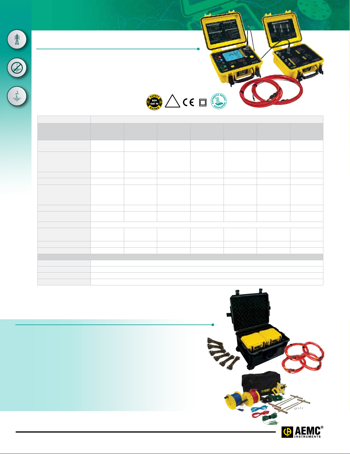
Tower Ground Resistance Tester
L
E
G
E
C
GroundFlex® Field Kit
N
A
T
S
E
V
I
L
T
S
E
T
Test active tower grounds safely
Y
S
T
E
M
without de-energizing or disconnecting
S
any cables. Unique in the industry!
E
G
N
I
R
M
O
R
U
E
N
T
D
E
D
C
Y
O
T
I
N
L
D
A
U
U
C
Q
T
O
R
SPECIFICATIONS
MODELS 6472 & 6474
ELECTRICAL
Range (Auto-Ranging)
Resolution
Accuracy
No-Load Voltage
Measurement
Frequency
Coupling Measurement
Auxiliary Rod
Resistance Measurement
Voltage Interference
Soil Resistivity
Type of Measurement
Measurement Current
MECHANICAL
Memory/Communication
Dimensions/Weight
Protection Safety
Electrical Safety
3-POINT
METHOD
0.01Ω to 99.9kΩ 0.001 to 99.99Ω 0.01 to 500Ω 0.01Ω to 99.9kΩ 0.01mV to 65.00V 0.001Ω to 99.9kΩ
0.01 to 100Ω 0.001 to 10Ω 0.01 to 1Ω 0.01 to 100Ω 0.01 to 10mV
± (2% + 1 count) ± (2% + 1 count) ± (10% + 1 count) ± (2% + 1 count) ± (5% + 1 count) ± (2% + 2 counts) ± (5% + 1 count)
16 or 32Vrms 16 or 32Vrms 16 or 32Vrms 16 or 32Vrms 16 or 32Vrms ± 16Vdc 16 or 32Vrms
41 to 5078Hz 41 to 5078Hz
Yes – – – – – –
0.1Ω to 100kΩ 0.01Ω to 100kΩ – – – – 0.01Ω to 100kΩ
– – –
3 wires 4 wires – 4 wires 3 wires 2 wires or 4 wires –
– – – – – > 200mA DC –
4-POINT
SELECTIVE
METHOD
10.7 x 9.84 x 5.04" (272 x 250 x 128mm) / Model 6472: 3.2 kg / Model 6474: 2.3 kg
50V CAT IV, complies with IEC 61326-1 / IEC 61010 / IEC 61557-1-4-5
IP
53
Rated
cover closed
GROUND
MEASUREMENT
WITH 2 CLAMPS
SOIL
RESISTIVITY
Auto: 1611Hz
Manual: 128Hz,
1367Hz, 1611Hz,
41 to 128Hz 41 to 128Hz DC 41 to 5078Hz
1758Hz
Maximum 60Vpeak
Wenner and
Schlumberger
512-record memory / optical link / USB
IP53 (cover closed)
GROUND
POTENTIAL
MEASUREMENT
DC
RESISTANCE
MEASUREMENT
2 wires:
0.01 to 100
4 wires:
0.001 to 10
– – –
MEASUREMENTS
Ω
Ω
WITH 6474
0.001Ω to
99.99k
Ω
0.001 to 10Ω
TEST KITS
Ground Tester Model 6472 Kit-500 ft
Includes meter, rechargeable NiMH batteries, optical USB cable, power adapter 110/240V with
power cord 115V US, two 500 ft color-coded leads on spools (red/blue), two 100 ft color-coded leads
(hand-tied, green/black), one 30 ft lead (green), four T-shaped auxiliary ground electrodes, one 100 ft
®
tape measure, DataView® software, ground tester workbook and user manual on USB stick,
AEMC
carrying bag for meter and carrying bag for kit. Catalog #2135.54
GroundFlex® Field Kit Model 6474
Includes GroundFlex
rings, connection lead, two extension leads on H reel (black/green) with color-coded alligator clips,
one extra black and green alligator clip, six BNC extension leads, calibration loop, three C-clamps,
carrying case with wheels and handle for meters, one inverter 12V
use) and user manual. Catalog #2136.03 (includes Cat. #2135.54)
www.aemc.com
®
Adapter Model 6474, four GroundFlex
®
sensors (5m) with twelve color-coded
dc to 120Vac 200 watt (vehicle
Technical Assistance (800) 343-1391
Page 2
GroundFlex® Field Kit
Current
4 AmpFlex® channels connected
FEATURES
• 3- and 4-Point Fall-of-Potential measurement
with manual or automatic frequency selection
• 4-Point soil resistivity measurement with automatic
calculation of Rho (ρ) and user selection of the
Wenner or Schlumberger test method
• 2- and 4-Wire DC resistance measurement
(Bond testing) with automatic polarity reversal
• 3-Point Earth coupling measurement
• Automatic frequency scan from 40 to 5078Hz
for optimum test accuracy in electrically noisy
environments
• Selectable test voltage limit of 16 or 32V
with up to 250mA of test current
• Automatic recognition of all electrode connections
and measurement of their resistance value
• Determines bonding condition of overhead
ground conductors
• Auto Power OFF management
• Optically isolated USB communication
• Remote set up and operation of all
measurements using DataView® software
supplied
• Automatic report generation
• Rechargeable NiMH batteries from wall
charger or vehicle power
• Rugged dustproof and rainproof field case —
IP53 rated in closed position
• IEC 61557 parts 4 and 5 compliant
• Includes DataView® software for data storage,
real-time display, analysis, report generation and
system configuration
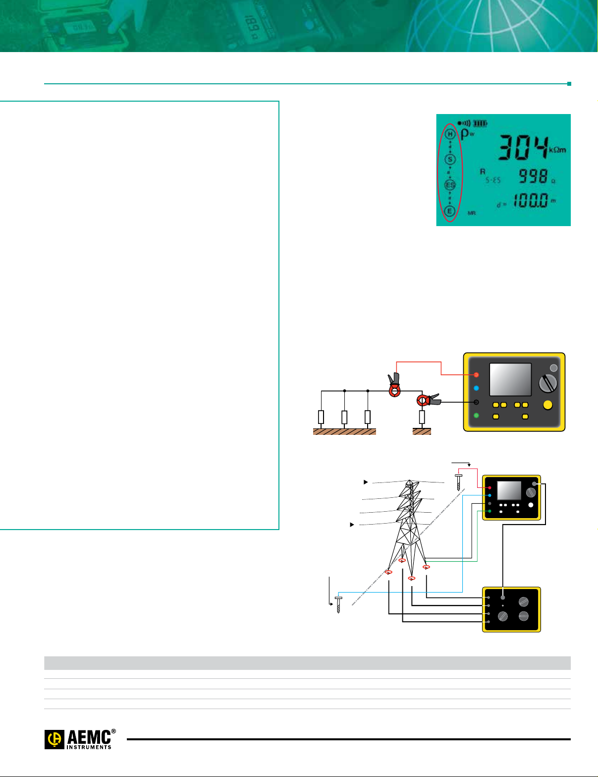
Ground measurement on towers with ground cable
High-voltage lines are usually equipped with a ground cable
to allow lightning to discharge to ground via the tower. As all
the towers are all connected to this conductor, all the tower's
resistances are in parallel. This means it is impossible to
measure tower resistance using traditional 3-Point methods
unless the ground cable is disconnected, which is a
dangerous and time-consuming operation.
Automatic recognition and
display of input connections
to match test
The connections are displayed
and flash if incorrect or absent
for the test selected.
Ground resistance measurement using 2 Clamps
For systems with parallel ground connections, the Model 6472 is
capable of accurately measuring a ground resistance using clamps
only. This method involves placing 2 clamps around the ground
conductor to be tested and connecting them each to the instrument.
One clamp injects a known signal (32V/1367Hz) while the other
clamp measures the current circulating in the loop. This method
saves considerable time when ground testing because it is no longer
necessary to set up auxiliary rods or to disconnect the ground
connector.
H
S
ES
E
R
H
H
S
ES
E
1
2
3
4
6472
6472
6474
Overhead
ground conductor
High voltage
line
Potential
measurement rod
R
S
R
E
injection
rod
4
3
1
2
CATALOG NO. DESCRIPTION
2135.54 Ground Resistance Tester Model 6472 Kit – 500 ft (Model 6472 and Cat. #2135.37)
2136.03 GroundFlex® Field Kit Model 6474 (Includes Cat. #2135.54)
2136.04 GroundFlex® Adapter Model 6474 w/{1} 10 m GroundFlex® Sensor
2136.05
GroundFlex
(Includes Cat. #2136.04 & Cat. #2135.54)
®
Adapter Model 6474 w/{1} 10 m GroundFlex® Sensor
Technical Assistance (800) 343-1391
www.aemc.com
Page 3

GROUND RESISTANCE TESTERS
GROUND RESISTANCE TESTERS
Multi-Function
Multi-Function
Ground Testers Models 6471 & 6472
Typical DataView® Functional Displays
2 Clamp Method Setup
Selective 3-Point Testing of Multiple Rods
Fall-of-Potential, Step-Touch Potential
4-Point Bonding For Very Low Resistance
Bonding
Soil Resistivity
OPTIONAL KITS
150 ft Kit 300 ft Kit 500 ft Kit
Catalog #2135.35
Test Kit for 3-Point
testing includes
carrying bag, two 150 ft
color-coded leads on spools (red/blue), two 5
ft color-coded leads (red/blue), one 30 ft lead
(green), two 14.5" T-shaped auxiliary ground
electrodes, one set of five spaded lugs and
100 ft tape measure.
Catalog #2135.36
Test Kit for 4-Point
testing includes
carrying bag, two 300
ft color-coded leads on spools (red/blue), two
5 ft color-coded leads (red/blue), two 100 ft
color-coded leads (green and black), four 14.5"
T-shaped auxiliary ground electrodes, one set
of five spaded lugs and 100 ft tape measure.
Catalog #2135.37
Test Kit for 4-Point
testing includes carrying bag,
two 500 ft color-coded leads on
spools (red/blue), two 5 ft color-coded leads
(red/blue), two 100 ft color-coded leads (green
and black), one 30 ft lead (green), four 14.5"
T-shaped auxiliary ground electrodes, one set
of five spaded lugs and 100 ft tape measure.
www.aemc.com
Technical Assistance (800) 343-1391
Page 4

POWER QUALITY ANALYZERS, METERS & LOGGERS
Three-Phase Power Quality Analyzer
GROUND RESISTANCE TESTERS
Software for Ground Resistance Testers
Multi-Function
Data Analysis and Reporting Software for Ground Testers
Configure all functions of
the Models 6417, 6471 & 6472
• Run tests and analyze real-time data from
your PC
• Configure all test functions and parameters
from your PC
• Customize views, templates and reports to
your exact needs
• Display Fall-of-Potential plots, tabular listings
of test results, resistance vs. frequency plots,
soil resistivity and bonding tests
(Models 6471 & 6472)
• Print reports using standard or custom
templates you design
• Free updates are available on our website
www.aemc.com
DATAVIEW®
Special
product
features
▼
DataView® software provides a convenient way to configure and
control ground resistance tests from your computer. Through the use
of clear and easy-to-use tabbed dialog boxes, all ground tester
functions can be configured and tests can be initiated. Results can
be displayed in real-time and stored in your PC. Reports may be
printed along with the operator’s comments and analysis.
Technical Assistance (800) 343-1391
www.aemc.com
 Loading...