

Page 1
n
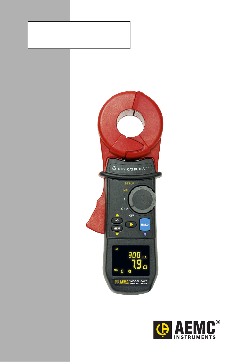
CLAMP-ON GROUND
RESISTANCE TESTER
6417
ENGLISH
User Manual
Page 2

Statement of Compliance
Chauvin Arnoux®, Inc. d.b.a. AEMC® Instruments
certifies that this instrument has been calibrated
using standards and instruments traceable to
international standards.
We guarantee that at the time of shipping your
instrument has met its published specifications.
An NIST traceable certificate may be
requested at the time of purchase, or obtained
by returning the instrument to our repair and
calibration facility, for a nominal charge.
The recommended calibration interval for this
instrument is 12 months and begins on the date of
receipt by the customer. For recalibration, please
use our calibration services. Refer to our repair
and calibration section at www.aemc.com.
Serial #: ________________________________
Catalog #: 2141.02
Model #: 6417
Please fill in the appropriate date as indicated:
Date Received: _________________________________
Date Calibration Due: _______________________
Chauvin Arnoux®, Inc.
d.b.a AEMC® Instruments
www.aemc.com
Page 3
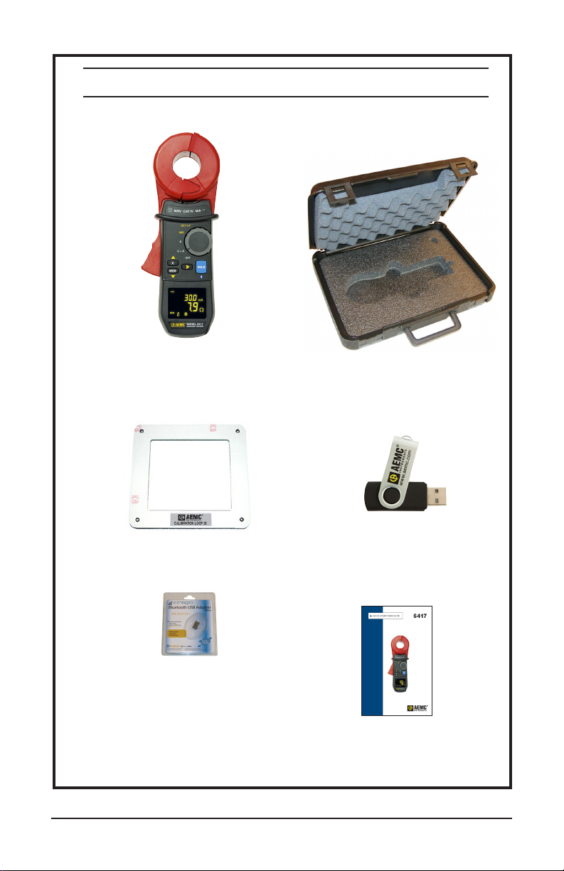
PRODUCT PACKAGING
Shipping Contents:
(1) Clamp-on Ground Tester
Model 6417
Cat. #2141.02
5W Calibration Loop
Cat. #2141.51
Bluetooth Adapter
Cat. #2126.45
Also Included:
(4) 1.5V AA Batteries
(1) Wrist Strap
(1) Safety Sheet (20 languages)
Hard Accessory Case
Cat. #2141.50
USB Stick with
DataView® Software & User Manual
Quick Start Guide
Clamp-on Ground Resistance Tester Model 6417
1
Page 4
Thank you for purchasing an AEMC Clamp-on Ground Resistance Tester.
For best results from your instrument and for your safety, read the enclosed
operating instructions carefully and comply with the precautions for use. These
products must be only used by qualied and trained users.
WARNING, risk of DANGER! The operator must refer to these instructions whenever
this danger symbol appears.
CAUTION! Risk of electric shock. The voltage at the parts marked with this symbol
may be dangerous.
Application or withdrawal authorized on conductors carrying dangerous voltages.
Type A current sensor as per IEC 61010-2-032.
Equipment is protected by double insulation.
The product has been declared recyclable after analysis of its life cycle in accordance
with the ISO14040 standard.
Important instructions to read and to fully understand.
Useful information or tip to read.
The CE marking guarantees conformity with European directives and with regulations
covering EMC.
The trash can with a line through it means that in the European Union, the product
must undergo selective disposal for the recycling of electric and electronic material,
in compliance with Directive WEEE 2002/96/EC.
Denition of Measurement Categories (CAT)
CAT IV Measurement Category IV corresponds to measurements taken at the
source of low-voltage installations.
Example: power feeders, counters and protection devices.
CAT III Measurement Category III corresponds to measurements on building
installations.
Example: distribution panel, circuit-breakers, machines or xed
industrial devices.
CAT II Measurement Category II corresponds to measurements taken on
circuits directly connected to low-voltage installations.
Example: power supply to domestic electrical appliances and portable
tools.
2 Clamp-on Ground Resistance Tester Model 6417
Page 5
PRECAUTIONS FOR USE
This instrument and its accessories comply with safety standards EN 61010-1,
EN 61010-030, and EN 61010-2-032 for voltages of 600V in Category IV at an
altitude of less than 2000m with a pollution degree of not more than 2.
Failure to observe the safety instructions may result in electric shock, re,
explosion, and destruction of the instrument and of the installations.
■ The operator and/or the responsible personnel must carefully read and clearly
understand the various precautions to be taken in use. Sound knowledge
and a keen awareness of electrical hazards are essential when using this
instrument.
■ If you use this instrument other than as specied, the protection it provides
may be compromised, thereby endangering you.
■ Do not use the instrument on networks of which the voltage or category
exceeds those mentioned.
■ Do not use the instrument if it seems to be damaged, incomplete, or poorly
closed.
■ Before each use, check the condition of the insulation on housing. Any item
of which the insulation is deteriorated (even partially) must be set aside for
repair or scrapping.
■ Use personal protection equipment systematically.
■ When handling the instrument, keep your ngers behind the physical guard.
■ All troubleshooting and metrological checks must be performed by competent
and accredited personnel.
■ Avoid impacts on the measurement head, in particular the air gap.
■ Keep the surfaces of the air gap clean; even a little dirt can cause the clamp
to malfunction.
■ All metal objects or wires connected to the electrical system should be
assumed to be lethal until tested. Grounding systems are no exception.
■ Use extreme caution when using the instrument around energized electrical
equipment.
■ Never attempt to use the instrument to twist or pry the ground electrode or
ground wire away from the equipment being grounded.
Clamp-on Ground Resistance Tester Model 6417
3
Page 6

Table of Contents
1. INTRODUCTION .............................................................................................7
1.1 Receiving Your Shipment......................................................................7
1.2 Ordering Information .............................................................................7
1.2.1 Replacement Parts ...................................................................7
2. PRODUCT FEATURES .....................................................................................8
2.1 Description ............................................................................................8
2.2 Features................................................................................................9
2.3 Applications...........................................................................................9
2.4 Display ................................................................................................10
2.5 Control Features .................................................................................12
2.6 Audible Signals ...................................................................................13
2.7 Rotary Switch Functions .....................................................................13
2.8 Button Functions .................................................................................14
3. PRINCIPLE OF OPERATION ..........................................................................15
4. SET-UP .......................................................................................................17
4.1 Menu Items .........................................................................................17
4.2 SET-UP Menu Displays ......................................................................17
4.3 Selecting a Specic Menu ..................................................................18
4.4 SET-UP Menus ...................................................................................18
5. OPERATION .................................................................................................22
5.1 Inserting the Batteries .........................................................................22
5.2 Setting the Date and Time ..................................................................22
5.3 Display Example .................................................................................23
5.4 Turning the Instrument ON .................................................................23
5.5 Turning Bluetooth ON .........................................................................24
5.6 Turning the Instrument OFF................................................................24
5.7 Standard and Advanced Modes..........................................................24
5.8 Memory ...............................................................................................25
5.8.1 Memory Capacity....................................................................25
5.8.2 Storing Measurements into Memory.......................................25
4 Clamp-on Ground Resistance Tester Model 6417
Page 7

5.8.3 Reading Stored Data ..............................................................25
5.8.4 Erasing the Memory ...............................................................25
5.8.5 Using the ▲ and ▼ Buttons ...................................................26
5.8.6 Exporting Data to a PC ...........................................................26
5.9 Alarm Management.............................................................................26
5.9.1 Voltage Alarm .........................................................................26
5.9.2 Current Alarm .........................................................................27
5.9.3 Impedance Alarm...................................................................27
5.9.4 No Alarm Detection.................................................................27
5.9.5 Priority of the Alarms ..............................................................28
6. MEASUREMENT MODES ..............................................................................29
6.1 Rotary Position Ω+A ...........................................................................29
6.1.1 Standard Mode .......................................................................29
6.1.2 Advanced Mode ......................................................................30
6.1.3 General Information ................................................................31
6.2 Rotary Position (A)..............................................................................32
6.2.1 Making a Measurement ..........................................................33
6.3 Rotary Position - (MR) ........................................................................33
6.3.1 Displaying Stored Measurements...........................................33
7. DATAVIEW® SOFTWARE ...............................................................................36
7.1 Installing DataView® ............................................................................36
7.2 Connecting the Instrument to a Computer ..........................................40
7.2.1 Bluetooth Connection .............................................................40
7.2.2 Pairing using Windows Vista / Windows 7/8/8.1/10 ................40
7.3 The Control Panel ...............................................................................42
7.3.1 Establishing Instrument Communication ................................43
7.4 Conguring the Instrument .................................................................44
8. ANDROID APPLICATION ..............................................................................46
9. SPECIFICATIONS .........................................................................................50
9.1 Reference Conditions .........................................................................50
9.2 Electrical .............................................................................................50
9.2.1 Loop Resistance Measurement ..............................................50
9.2.2 Loop Inductance Measurement ..............................................51
9.2.3 Contact Voltage (Touch Voltage) ............................................51
Clamp-on Ground Resistance Tester Model 6417
5
Page 8

9.2.4 Current Measurement.............................................................51
9.2.5 Power Supply .........................................................................52
9.3 Environmental .....................................................................................52
9.4 Mechanical..........................................................................................52
9.5 Safety..................................................................................................53
10. MAINTENANCE ..........................................................................................54
10.1 Cleaning............................................................................................54
10.2 Battery Replacement ........................................................................54
10.3 Repair and Calibration ......................................................................55
10.4 Technical and Sales Assistance ........................................................55
10.5 Limited Warranty ...............................................................................56
10.6 Warranty Repairs ..............................................................................56
6 Clamp-on Ground Resistance Tester Model 6417
Page 9

1. INTRODUCTION
1.1 Receiving Your Shipment
Upon receiving your shipment, make sure that the contents are consistent with
the packing list. Notify your distributor of any missing items. If the equipment
appears to be damaged, le a claim immediately with the carrier and notify
your distributor at once, giving a detailed description of any damage. Save the
damaged packing container to substantiate your claim.
1.2 Ordering Information
Clamp-on Ground Resistance Tester Model 6417 ....................... Cat. #2141.02
Includes a hard carrying case, Bluetooth USB adapter, calibration loop, four 1.5V
AA batteries, quick start guide, and USB stick with DataView® software and user
manual.
1.2.1 Replacement Parts
Bluetooth USB Adapter Class 2........................................................Cat. #2126.45
Wrist Strap ........................................................................................Cat. #2135.47
Hard Carrying Case .......................................................................... Cat. #2141.50
5W Calibration Loop .......................................................................... Cat. #2141.51
Order Accessories and Replacement Parts Directly Online
Check our Storefront at www.aemc.com for availability
Clamp-on Ground Resistance Tester Model 6417
7
Page 10

2. PRODUCT FEATURES
2.1 Description
The Clamp-on Ground Resistance Tester Model 6417 measures grounding
electrodes and grid resistance without the use of auxiliary rods. Clamp-on ground
resistance testers can be used in multi-grounded systems without disconnecting
the ground system under test. The Model 6417 simply clamps around the
ground conductor or rod and measures the resistance to ground. By performing
measurements on intact ground systems, the user also veries the quality of the
grounding connections and bonds. Resistance and continuity of grounding loops
around pads and buildings can also be measured.
The Model 6417 includes a current measurement function. The ground tester’s
high sensitivity enables measurement of leakage current owing to ground or
circulating in ground loops from 0.2mA to 40A and resistances from 0.01 to
1500W.
Battery life information is displayed at power-up and the Auto Power OFF feature
can be enabled for power management. Additional features include the large
OLED (Organic Light Emitting Diode) display that ensures high readability of
data. The Buzzer and Auto Power OFF features can be disabled at any time.
The Model 6417 is equipped with an alarm function and a data storage function.
In the Alarm mode, the probe will audibly and visually indicate when the reading
is beyond an input set point. You can also have the alarm activate above or
below the set point. This alarm feature permits quick eld checks where only
“pass” or “fail” readings are required.
The data storage function logs up to 2000 measurements (W and/or A). This
enables you to conduct eld surveys, and to retrieve and analyze the readings at
a later time. The alarm settings and stored data are saved on the ground tester
and remain stored even when the instrument is turned OFF. You can retrieve and
analyze the results at a later time with DataView® software or with an Android app
through the Bluetooth communication port.
Two new features unique to AEMC® are test frequency selection and touch
voltage indication.
The ability to select the test frequency provides more accurate measurements in
inductive environments.
Displaying voltage derived from current and resistance measurements provides
an extra level of safety for the user, indicating a potentially dangerous touch
condition.
8 Clamp-on Ground Resistance Tester Model 6417
Page 11

2.2 Features
■ Simple and fast clamp-on operation - no leads, no auxiliary rods or spacing
requirements
- Ammeter: Current measurements from 0.2mA to 40A.
- Loop ohmmeter: Measurement of loop impedances from 0.01 to 1500W.
The ohmmeter function makes allowance for the presence of inductances
in the loop, making impedance measurements more accurate at low
values.
- Contact voltage: The contact voltage is determined by calculating the
product of the loop impedance and leakage current. The value found is an
upper bound on the voltage between the measurement point and earth,
since the impedance taken into account is that of the whole loop.
■ Touch voltage display
■ Large multi-function, bright yellow organic light emitting diode display (OLED)
■ Display in Standard mode (one screen) or Advanced mode (three screens)
■ Clamping diameter of 1.38" (35mm) accommodating cables up to 1000kcmil
■ Stores up to 2000 measurements (W and/or A, with time-stamping)
■ Displays stored measurements on the display or via Bluetooth® to a PC
■ Measurement hold by the HOLD and AUTO-HOLD functions
■ Clamp opening made easy by a trigger with a force compensation system
■ Auto Power OFF function
■ Alarm function with adjustable set point and buzzer for quick eld checks
■ Rugged Lexan® head and body construction resists breakage
■ Alarm settings and stored memory information saved during shutdown
■ NOISE icon and buzzer notify the user to presence of dangerous voltage and
current levels
■ Designed to EN 61010-1, 600V CAT IV safety standards
2.3 Applications
■ Ground electrode system resistance
■ Bonding/continuity checks
■ Cell tower grounding verication
■ Ground measurements on Railroad signaling systems
Clamp-on Ground Resistance Tester Model 6417
9
Page 12

2.4 Display
The Model 6417 is equipped with a 152-segment OLED (organic light-emitting
diode) display. This OLED technology results in a thinner, lighter, sharper, higher
contrast display compared to LCD displays.
202122
1
2
3
4
5
6 7
8
9 10 11 12
Figure 2-1
16
171819
Item Description
1
Indicates selection of Advanced mode.
In Advanced mode, this indicates when the inductive component is negligible with
2
respect to the resistive component.
Main Display:
3
- Measurement of the impedance or current.
- Display of the date and time (month-day and hour-minute) in configured and
stored values display mode.
In Advanced mode, these symbols identify the value displayed (resistance or
4
impedance).
5
Data storage mode.
6
Memory recall mode.
Memory index four-digit digital display (0 to 9999-counts):
7
- Measurement sequence number of the current memory in normal operation
associated with the Recall (MR) or Storage (MEM) indications.
- Date stamp (year) when the device is configured.
8
9
- Blinks while the Bluetooth connection is being established.
- On steady for the duration of Bluetooth communication.
Signal indicating potentially hazardous voltage. Blinks when the contact voltage
exceeds 50V.
15
14
13
10 Clamp-on Ground Resistance Tester Model 6417
Page 13
Alarm threshold high/low indicator (operational use or configuration):
10
▲ Alarm threshold high indicator.
AL Alarm threshold adjustment mode or Alarm function.
▼ Alarm threshold low indicator.
Alarm threshold display:
11
- Display of one of the alarms (1000-count display) with units.
- These three digits are also used when configuring the time display mode.
(A for A.M., P for P.M. or 24H) in SET-UP (see § 4.4, menu #8).
Unit of the alarm displayed. The alarm can be defined on a resistance impedance,
voltage, or current, depending on the measurement chosen (W+A or A).
12
- A: Current measurement alarm.
- W: Resistance measurement alarm.
- V: Voltage measurement alarm.
Unit of the central measurement display:
13
- V: Contact voltage measurement unit.
- W: Impedance measurement unit. Symbol used for impedances at the
measurement frequency, for impedances referred to the network frequency, or
for the resistive component.
Unit of the top measurement display:
14
- mH: Loop inductance measurement unit.
- mA or A: Current measurement unit.
Upper display: 4000-count current measurement and 500-count loop inductance
15
measurement (Advanced mode).
Battery charge indicator:
- Not displayed: Batteries charged.
16
- Blinking: Batteries low. The device remains functional, but the batteries will
have to be replaced soon.
- Steady: Batteries discharged. The display indicates Lo bat. It is not possible to
make measurements, read records, or configure parameters.
Continuous operation of the clamp (Auto Power OFF disabled).
17
Selection of Auto Power OFF mode is made in SET-UP (see § 4.4, menu #3).
Symbol indicating incorrect closing of the clamp; measurements cannot be made
in this case. If the AUTO-HOLD mode is activated, the HOLD icon blinks and the
18
measurement is frozen. Selection of AUTO-HOLD mode is made in SET-UP (see § 4.4,
menu #11).
Symbol indicating the presence of disturbance (current) in the loop, which
19
compromises the accuracy of the impedance measurement.
Indicates that the main display shows the date (when the rotary switch is set to MR
20
or SET-UP).
Indicator of freezing the measurement display when the HOLD button is pressed or
21
while in the AUTO-HOLD mode.
Display of the buzzer’s active state; the icon is not shown when the buzzer is inactive.
22
Selection of the buzzer operating mode is made in SET-UP (see § 4.4, menu #2).
Clamp-on Ground Resistance Tester Model 6417
11
Page 14
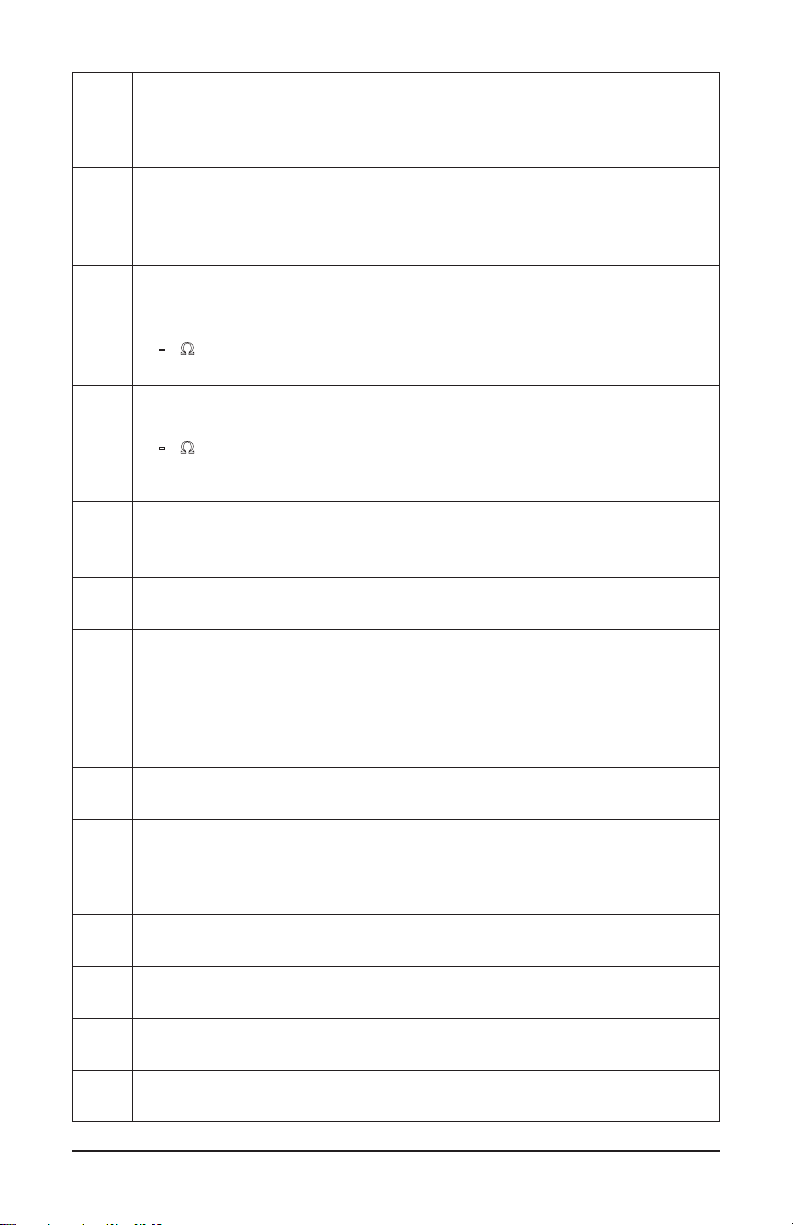
2.5 Control Features
1
2
3
6
0
0
V
SET-UP
MR
A
A
0
4
C
V
I
A
T
8
MEM
OFF
HOLD
9
4
5
6
7
Figure 2-2
1. Head Assembly: Consists of two individually shielded magnetic cores
2. Guard: Safety guard; do not place hands above this guard
3. Lever: Opens or closes the jaws
4. : Toggles display backlight ON/OFF
5. MEM: Stores measurements into memory
6. ►: Navigates and validates measurement displays
7. OLED Display: Crisp, clean and bright display
8. Rotary Switch: Selects measurement functions and instrument SET-UP
9. HOLD: Freezes last measured value on the display
Turns Bluetooth ON/OFF (when switch is set to MR or SET-UP)
12 Clamp-on Ground Resistance Tester Model 6417
Page 15
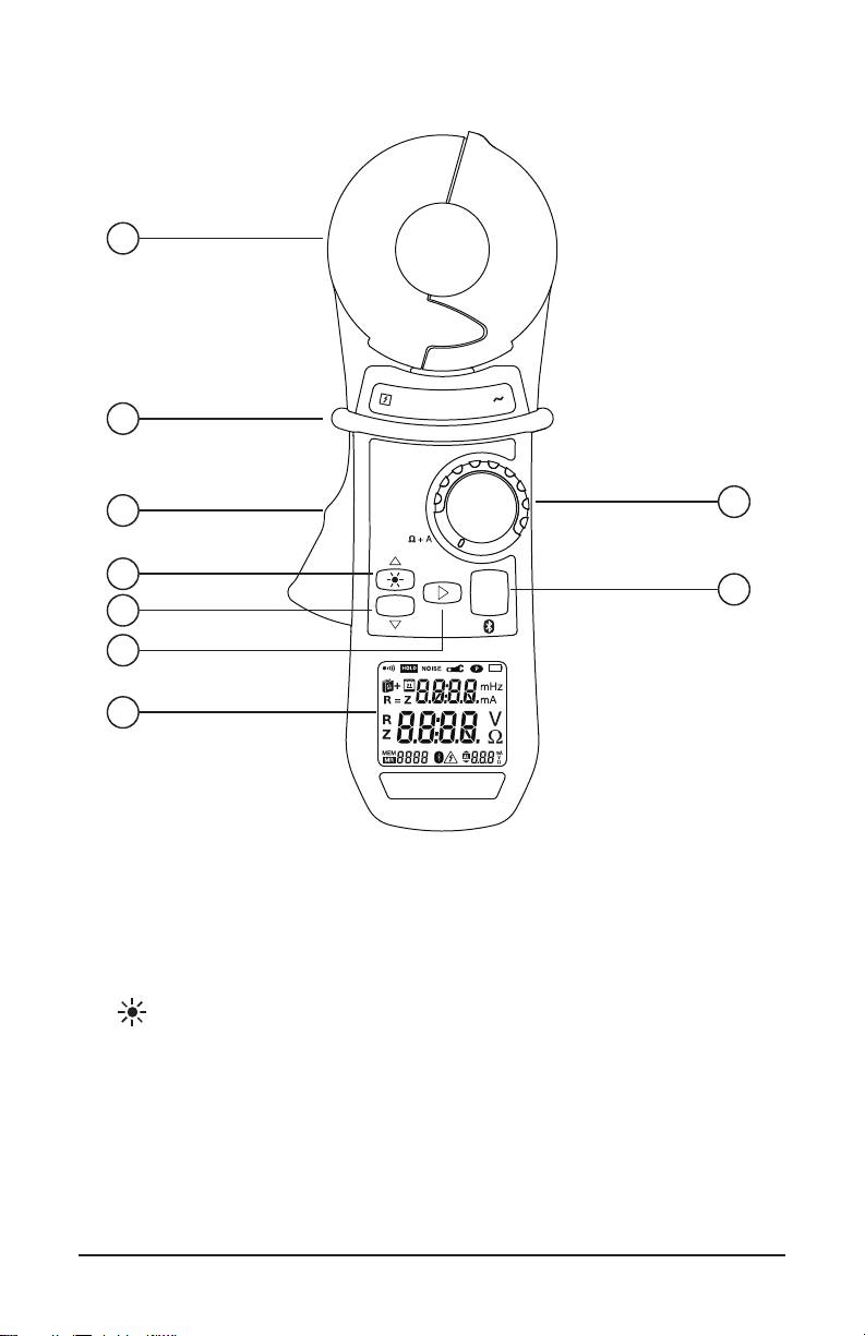
2.6 Audible Signals
There are four audible signals:
Type Duration Description
Low-pitched
High-pitched
Audible signals can be enabled or disabled in SET-UP (see § 4.4, menu #2).
The symbol indicates:
Visible
Not Visible
This programming is backed-up and retrieved at each reset.
During a measurement, a long press on the ► button toggles between activation
and deactivation of the buzzer.
NOTE: Since the measurement frequency is audible, the operator hears a beeping
signal. This is neither an operating fault nor an alarm, and it cannot be eliminated.
This audible signal is amplified by the presence of current in the loop.
Short Normal use (button pressed).
Permanent High/Low alarm threshold (W, A) triggered.
Short Abnormal use (for example, memory full).
Permanent Alarm threshold (V) exceeded.
Description
Buzzer enabled; an alarm or a button press causes an audible signal to be
emitted.
No audible signal is emitted.
2.7 Rotary Switch Functions
Range Description
OFF
Ω+A
A
MR
SET-UP
Clamp-on Ground Resistance Tester Model 6417
Instrument is powered OFF.
Simultaneous selection of the loop impedance measurement and the leakage
current measurement.
Current measurement selection
Displays stored measurements.
Access to the instrument configuration and deletion of stored measurements.
13
Page 16
2.8 Button Functions
Button Description
• When the rotary switch is set to W+A or A: Increases the brightness
▲
of the display, making it easier to read the display in an environment with
strong background illumination. Highlighting activated for 30 seconds.
• When the rotary switch is set to SET-UP or MR: Serves as the ▲
arrow when browsing in the menus and values. The brightness of the
display does not change when device is set to SET-UP or MR.
MEM
▼
►
HOLD
&
AUTO-HOLD
• When the rotary switch is set to W+A or A: Records the measured
value. All of the data is recorded in the Standard or Advanced mode.
• When the rotary switch is set to SET-UP or MR: Serves as the ▼
arrow when browsing in the menus and values.
• When the rotary switch is set to W+A (Advanced Mode):
Short Press: Switches the display through the following three modes:
- Display of the impedance recalculated at the selected frequency.
- Display of the contact voltage (product Z*I).
- Display of R and L.
Long Press: Enables or disables the audible alarms.
• When the rotary switch is set to SET-UP:
- Validation when browsing in the menus and values.
• When the rotary switch is set to MR (Advanced Mode):
- Switches the display through the measurement screens and the
measurement date/time.
• When the rotary switch is set to W+A:
- Freezes the displayed measurement for as long as the HOLD button
is pressed. The NOISE, clamp open ( ), and alarm exceedence ( )
icons are visible, if they were active.
• When the rotary switch is set to MR or SET-UP:
- Enables or disables the Bluetooth® connection.
• AUTO-HOLD Function:
If the AUTO-HOLD mode was enabled during instrument SET-UP (see
§ 4.4, menu #11), opening the clamp acts as the identical state to the
HOLD mode for as long as the clamp is open. The benefit of this function
is that it makes it easy to freeze the measurement with one hand, when
access to the HOLD button is difficult.
If the HOLD button is not pressed during this time, closing the clamp
automatically exits the AUTO-HOLD mode.
14 Clamp-on Ground Resistance Tester Model 6417
Page 17
3. PRINCIPLE OF OPERATION
1
Σ
Ri
1
Σ
Ri
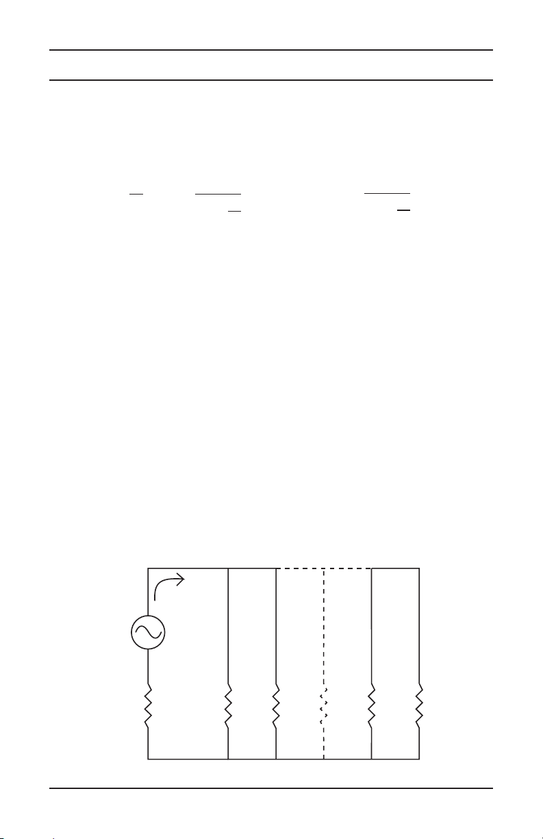
Typically, a grounded distribution system can be simulated by the basic circuit
shown in Figure 3-1 or an equivalent to the diagram shown in Figure 3-2. If
voltage (V) is applied to any measured grounding electrode Rx through a
special transformer; current (I) ows through the circuit, thereby establishing the
following equation:
V
= Rx +
I
Therefore, V/I = Rx is established. If I is detected and measured with V kept
constant, the measured grounding electrode resistance Rx can be obtained.
A signal is fed to a special transformer via a power amplier from a 2403Hz
constant voltage oscillator. The resulting current is then sensed by a detection
CT (current transformer). An active lter is used to dampen earth current at
commercial frequency (50/60Hz) and high-frequency noise.
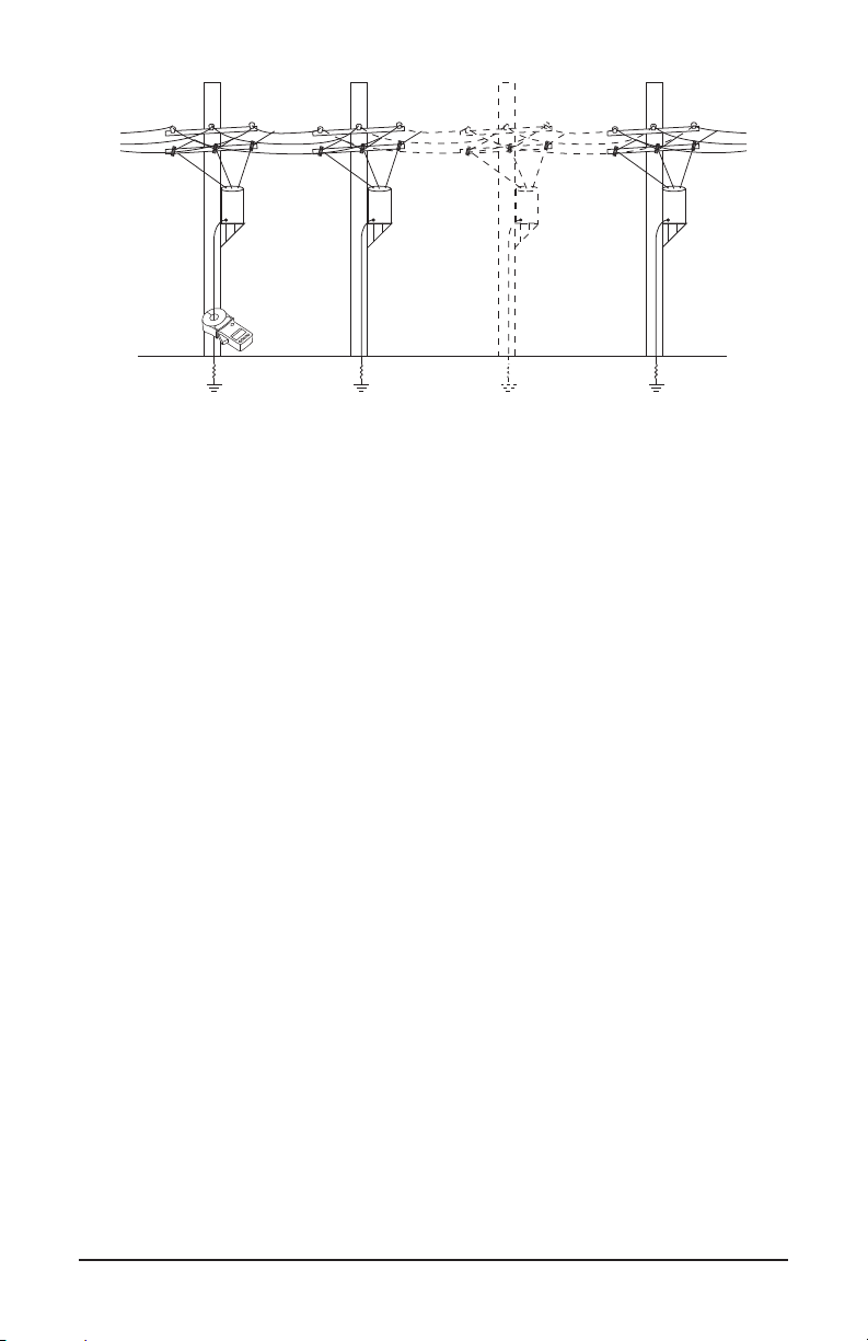
Example: If clamped around any grounding electrode in a multi-grounded
system, the measured value of the electrode under test will be the resistance
of that particular rod in series with the equivalent parallel resistance value that
the rest of the multi-grounded system represents. If an electrical system had
101 grounding electrodes and each had a resistance value of 25W, and it were
clamped around any electrode in the system, the measured value would be 25W
in series with the equivalent parallel resistance of the other 100 electrodes or
0.25W. The displayed value would be 25.2W (instrument resolution to 0.1W).
n
i=1
where, usually
1
Rx »
n
i=1
1
V/I = 25W + 0.25W
Rx = 25.2W
In most eld applications, the number of electrodes that make up a multi-
grounded system would be higher; therefore the equivalent parallel resistance is
negligible with respect to the rod under test.
I
V
Rx R1 R2 Rn-1 Rn
Figure 3-1
15
Clamp-on Ground Resistance Tester Model 6417
Page 18
Rx R1 RnRn-1
Figure 3-2
16 Clamp-on Ground Resistance Tester Model 6417
Page 19

4. SET-UP
Turn the rotary switch to the SET-UP position.
4.1 Menu Items
The SET-UP position gives access to the following options to set user dened
parameters for instrument conguration:
No. Function
1 Erases stored measurements.
2 Enables/disables the buzzer.
3 Enables/disables Auto Power OFF
4 Sets the impedance alarm threshold (W).
5 Sets the voltage alarm threshold (V).
6 Sets the current alarm threshold (I).
7 Sets the date.
8 Sets the time.
9 Selects the Standard or Advanced operating mode.
10 Selects the test frequency for the impedance.
11 Enables/disables the AUTO-HOLD mode.
12 Displays the version number.
13 Not used.
4.2 SET-UP Menu Displays
The 12 accessible menus (listed
above) are clearly identied by their
title and number, as shown in the
example in Figure 4-1 (menu #5)
which displays the voltage alarm
threshold adjustment (AL. V).
Clamp-on Ground Resistance Tester Model 6417
Figure 4-1
17
Page 20

4.3 Selecting a Specific Menu
Use the buttons as follows to select a specic menu item:
Button Action
▲ Move up in the menu tree.
▼ Move down in the menu tree.
► Select the menu displayed or return to the previous menu.
NOTE: When changes have been made in one of the SET-UP menus, the changes
can be cancelled by turning the rotary switch to a position other than SET-UP,
provided that there has not been a return to the main menu (by pressing ►).
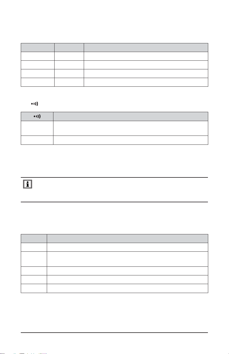
4.4 SET-UP Menus
Menu # Indication Function
Erasing the Memory:
■ Enter the menu by ►. Clr blinks.
1 CLr
■ Press ▲ and ▼ simultaneously for 6 seconds. All
recorded data is erased. The meter indicates
MEM 0.
■ Return to the previous menu by ►.
Enabling/Disabling the Buzzer:
■ Enter the menu by ►. Snd blinks.
■ Press ▲ or ▼.
2 Snd
3 StOP
■ The Buzzer is enabled when the icon is visible
and disabled when it is masked.
■ Return to the previous menu by ►.
NOTE: In the Ω+A and A measurement modes, a long
press on ► activates or deactivates the audible alarms.
Enabling/Disabling Auto Power OFF:
■ Enter the menu by ►. StOP blinks.
■ Press ▲ or ▼.
■ Auto Power OFF is deactivated when the icon is
visible and activated when it is hidden.
■ Return to the previous menu by ►.
18 Clamp-on Ground Resistance Tester Model 6417
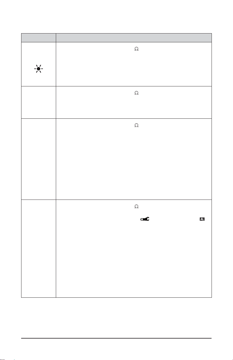
Page 21

Menu # Indication Function
Setting the Impedance Alarm Threshold (Ω):
■ Enter the menu by ►. AL. W blinks.
■ Press ▲ or ▼ to select the state of the alarm:
- : Disabled.
Enabled for a measurement exceeding the
- :
threshold.
4 AL. Ω
Enabled for a measurement below the
- :
threshold.
■ Validate by ►.
Setting the Alarm Value:
■ Press ▲ or ▼ to select the impedance alarm
threshold (Figure 2-1, item #11).
■ Validate and return to the previous menu by ►.
Setting the Voltage Alarm Threshold (V):
■ Enter the menu by ►. AL. V blinks.
■ Press ▲ or ▼ to select the state of the alarm
(Figure 2-1, item #10):
- : Disabled.
Enabled for a measurement exceeding the
5 AL. V
- :
threshold.
■ Validate by ►.
Setting the Alarm Value.
■ Press ▲ or ▼ to select the alarm threshold value
(Figure 2-1, item #11).
■ Validate and return to the previous menu by ►.
Setting the Current Alarm Threshold (I):
■ Enter the menu by ►. AL. A blinks.
■ Press ▲ or ▼ to select the state of the alarm
(Figure 2-1, item #10):
- : Disabled.
Enabled for a measurement exceeding the
6 AL. A
- :
threshold.
■ Validate by ►.
Setting the Alarm Value.
■ Press ▲ or ▼ to select the current alarm threshold
(Figure 2-1, item #11).
■ Validate and return to the previous menu by ►.
Clamp-on Ground Resistance Tester Model 6417
19
Page 22

Menu # Indication Function
Setting the Date:
■ Enter the menu by ►. dAtE blinks.
■ Press ▲ or ▼ to select the year. Validate by ►.
7 dAtE
8 HOUR
9 USE
■ Press ▲ or ▼ to select the month. Validate by ►.
■ Press ▲ or ▼ to select the date.
■ Validate and return to the previous menu by ►.
NOTE: In some locations the order of the date values is
displayed as Year, Date, Month.
Setting the Time:
■ Enter the menu by ►. HOUR blinks.
■ Press ▲ or ▼ to select the AM/PM (A. or P.) or 24H
display mode (24H), which blinks. Validate by ►.
■ Press ▲ or ▼ to select the hour, which blinks.
Validate by ►.
■ Press ▲ or ▼ to select the minutes value, which
blinks.
■ Validate and return to the previous menu by ►.
Selecting Standard or Advanced Operating Mode:
■ Enter the menu by ►. USE blinks.
■ Press ▲ or ▼ to select the Standard or Advanced
mode.
- Advanced Mode: The icon is displayed.
- Standard Mode: Std is displayed.
■ Validate and return to the previous menu by ►.
Choosing the Test Frequency for the Impedance in
Advanced Mode:
■ Enter the menu by ►. FrEQ blinks.
10 FrEQ
■ Press ▲ or ▼ to select the transposition frequency
of the measured impedance from among the four
possible values: 50, 60, 128, and 2083 Hz.
■ Validate and return to the previous menu by ►.
20 Clamp-on Ground Resistance Tester Model 6417
Page 23

Menu # Indication Function
Enabling/Disabling the AUTO-HOLD Mode:
■ Enter the menu by ►. HOLd blinks.
■ Press ▲ or ▼ to switch the AUTO-HOLD mode to
active or inactive.
11 HOLd
- AUTO-HOLD Mode Disabled: Only the
icon is displayed.
- AUTO-HOLD Mode Enabled: The and
icons are displayed.
■ Validate and return to the previous menu by ►.
Displaying the version number
12 VER
■ Enter the menu by ►.
■ The version number is displayed.
■ Return to the previous menu by ►.
13 CAL
Reserved for factory use - not used for normal
operation
Clamp-on Ground Resistance Tester Model 6417
21
Page 24

5. OPERATION
5.1 Inserting the Batteries
■ Unclamp and remove the instrument
from any connections and turn the rotary
switch to the OFF position.
■ Use a Philips head screwdriver to
unscrew the two attachment screws and
remove the battery compartment cover.
■ Remove the old batteries and replace
+++
+
Figure 5-1
NOTE: The alkaline batteries can be replaced by NiCd or NiMh rechargeable
batteries (AA, 1.2V) having similar characteristics. However, the time between
the low battery message and the Auto Power OFF will be shorter with the
rechargeable batteries.
them with four new batteries (LR6, AA,
1.5V), observing the polarities.
■ Close the battery compartment cover and
tighten the two screws.
■ Check for the proper operation of the
device.
Used batteries must not be treated as ordinary household waste. Recycle
them appropriately.
5.2 Setting the Date and Time
Setting the clock, which is used for time-stamping measurements, is done only
the rst time the clamp is used or after it has been without battery power for more
than two minutes.
Set the function switch to Ω+A. All icons on the display light for approximately
two seconds. Enter the date and time using the ▲, ▼, and ► buttons.
The date and time can also be congured before a measurement in SET-UP (see
§ 4.4, menu #7 & #8).
NOTE: If time-stamping is not needed, this operation can be skipped by pressing
the ► button until the measurement screen corresponding to the switch setting
(Ω+A, A, MR or SET-UP) is displayed.
22 Clamp-on Ground Resistance Tester Model 6417
Page 25

5.3 Display Example
Figure 5-2 shows a typical display upon
rst use, with the device set to Ω+A. In
this example the measured current is
30.0mA and the impedance is 7.9W.
The buzzer is active and the memory is
empty.
NOTE: This display corresponds to the
device in Standard mode. In Advanced
mode, two additional screens are
available (see § 6.1.2.2).
Figure 5-3 shows a display, upon rst
use, with the device set to A. In this
example, the current measured is
30.0mA.
The buzzer is active and the memory is
empty.
Figure 5-2
Figure 5-3
5.4 Turning the Instrument ON
With the clamp closed and not clamped around any conductor, set the rotary
switch to a position other than OFF. All icons on the display light for approximately two seconds, before possible entry of the date and time (see § 5.2).
During the rst few seconds of operation, the clamp automatically adjusts correction factors to optimize the impedance measurement. This correction makes
it possible to allow for the variations of the measurement head air gap that may
occur in some temperature and humidity conditions.
During this adjustment, the screen displays CAL GAP. If the clamp detects a
problem, it indicates Err CAL when the switch is set to Ω+A. Turn the instrument
OFF, disconnect it from any conductor and make sure the sensor heads are
clean with no obstructions, then turn it back ON.
When this adjustment is done, the clamp displays the screen corresponding to
the switch setting.
Clamp-on Ground Resistance Tester Model 6417
23
Page 26

5.5 Turning Bluetooth ON
1. Rotate the rotary switch to the MR or Setup position.
2. Press and release the HOLD / button.
■ When Bluetooth (BT) is ON you will see a ashing Bluetooth icon ( ) at the
bottom of the display.
■ To turn Bluetooth OFF, repeat the steps given above.
■ Once Bluetooth is ON you can rotate the rotary switch to any position (except
OFF) and the Bluetooth will remain ON.
5.6 Turning the Instrument OFF
The instrument can be turned OFF in two ways:
■ Manually: Turn the rotary switch to OFF.
■ Auto Power OFF: This function activates after 5 minutes of no activity (no
button press, no change of switch setting, and no opening of the jaws).
- Fifteen seconds before Auto Power OFF, a short audible signal is emitted
and the display blinks once a second.
Auto Power OFF can be disabled in SET-UP (see § 4.4, menu #3). The
symbol is then displayed.
5.7 Standard and Advanced Modes
The instrument has two modes.
■ Standard Mode: Makes the standard loop resistance and leakage current
measurements.
■ Advanced Mode: Used to rene and complete the measurements:
- Impedance at the selected frequency.
- Contact voltage.
- Resistive and inductive components of the loop impedance.
The choice of Standard or Advanced mode and the alarm thresholds are
congured in SET-UP (see § 4.4, menu #9).
24 Clamp-on Ground Resistance Tester Model 6417
Page 27

5.8 Memory
5.8.1 Memory Capacity
The Model 6417 has a recording capacity of 2000 measurements. The PC
interface can be used to activate a circular (rst in/rst out) recording mode in
which the 2000 most recent values are kept, with a maximum sequence number
of 9999. If the circular recording mode is activated; as soon as the threshold of
2000 values is exceeded, the sequence number is displayed alternately with
FULL in order to report the overwriting of the oldest records. When the threshold
of 9999 records is reached, the sequence number is replaced by FULL. The
next time the MEM button is pressed, a beep is emitted and the FULL indication
blinks.
5.8.2 Storing Measurements into Memory
The values displayed during the measurements can be stored in memory and
read later.
Storage of the data is available in both the Ω+A and A measurement modes,
provided that memory locations are free.
Data is stored as soon as the MEM button is pressed. A long audible signal
conrms the storage.
All calculated impedance and/or current values, together with the values
accessible in the secondary screens in Advanced mode, are stored as soon as
the MEM button is pressed, such as:
■ Current measurement (A)
■ Measurement of the resistance, inductance, and impedance (Z)
■ Contact voltage measurement (V)
■ Present conguration of the clamp
■ Sequence number of the record
■ Time and date of the record
The display indicates the sequence number of the last measurement recorded,
or 0 if the memory is empty. The data is preserved when the device is OFF or
without a battery.
5.8.3 Reading Stored Data
The data can be read using the MR function (see § 6.3).
5.8.4 Erasing the Memory
Refer to § 4.4, menu #1.
Clamp-on Ground Resistance Tester Model 6417
25
Page 28

5.8.5 Using the ▲ and ▼ Buttons
The ▲ and ▼ buttons are used to view the various stored measurements.
If these buttons are held down, the sequence number is scrolled at a rate
of 3 counts per second; after 5 seconds, the rate is increased to 10 counts
per second. Each time the sequence number changes, the value of the
corresponding measurement is displayed. The MR symbol remains displayed as
a reminder that the memory recall function is active.
It is possible to scroll past the oldest recorded value to the most recent, or past
the most recent recorded value to the oldest.
When circular recording is activated, the sequence number of the oldest record is
not necessarily 1: the remaining records may be numbered from 44 to 2043, for
example.
5.8.6 Exporting Data to a PC
The Model 6417 has a communication capability and can transfer the recorded
measurements to a PC using the supplied DataView software (see § 7).
5.9 Alarm Management
The device has three distinct alarms that can be congured.
NOTE: The (W, V, A) alarm thresholds can be configured in SET-UP (see §4.4).
5.9.1 Voltage Alarm
■ If the voltage (product ZxI) exceeds
the threshold set, the alarm symbol
and the alarm threshold blink.
■ If the buzzer is active, a high-pitched
audible warning signal is emitted.
Figure 5-4
26 Clamp-on Ground Resistance Tester Model 6417
Page 29

5.9.2 Current Alarm
■ If the current exceeds the threshold
set, the alarm symbol and the alarm
threshold blink.
■ If the buzzer is active, a low-pitched
audible signal is emitted.
Figure 5-5
5.9.3 Impedance Alarm
If there is no voltage alarm, no detection of noise, and no current alarm, an alarm
on the impedance may be triggered. If the buzzer is enabled, the corresponding
audible signal is emitted.
■ Low Threshold Conguration:
An audible signal is emitted when the
impedance is below the threshold set
(continuity type measurement).
■ High Threshold Conguration:
An audible signal is emitted at values
exceeding the threshold (detection
of a grounding impedance that is too
high).
Figure 5-6
If the impedance crosses the selected threshold, a low-pitched audible signal is
emitted.
5.9.4 No Alarm Detection
If no alarm is activated, the alarm icons are not displayed.
■ When no alarm is triggered, the
alarm threshold is displayed,
along with the direction
of triggering ( , ) of the
impedance, voltage, or current
alarm.
Figure 5-7
Clamp-on Ground Resistance Tester Model 6417
27
Page 30

5.9.5 Priority of the Alarms
If several alarms are triggered simultaneously, a priority rule determines the
display and the corresponding sound:
■ The voltage alarm has priority because it concerns the user’s safety.
■ The current alarm is second in priority.
■ The impedance alarm is displayed when no other alarm is triggered.
28 Clamp-on Ground Resistance Tester Model 6417
Page 31

6. MEASUREMENT MODES
6.1 Rotary Position W+A
6.1.1 Standard Mode
Selection of Standard mode is performed in the SET-UP (see § 4.4, menu #9).
In Standard mode, only one measurement screen is available. The clamp
measures the loop impedance (W) (at the xed frequency of 2083Hz) and the
leakage current.
NOTE: Since the measurement frequency is audible, the operator hears a beeping
signal. This is neither an operating fault nor an alarm, and it cannot be eliminated.
This audible signal is amplified by the presence of current in the loop.
The alarm thresholds can be congured as desired (see § 4.4, menus #4, #5 &
#6).
6.1.1.1 Making a Measurement
■ Turn the rotary switch to the Ω+A position, and wait several seconds
while the instrument performs internal calibration.
■ Clamp around the conductor to be measured. If the clamp is incorrectly
closed, the icon is displayed.
■ If necessary, use the HOLD button to freeze the measurement.
■ If necessary, use the MEM button to store the measurement.
NOTE: If the measured impedance is less than 1W, the measurement display
alternates between the value measured and the word LOOP, in order to call the
user’s attention to the risk of measuring a local loop at the test point that does
not include the earth/ground measurement.
Clamp-on Ground Resistance Tester Model 6417
29
Page 32

6.1.1.2 Measurement Results
Once the measurement has stabilized, the display
indicates:
- The leakage current.
- The impedance of the loop at the frequency of
2083Hz.
The impedance is measured only if the leakage
current is less than 10A. In the 10 to 40A range,
only the current is displayed; the NOISE symbol
blinks and the impedance is replaced by dashes.
To store the measurement into memory, press the MEM button (see § 5.8.2).
If the contact voltage exceeds 50V, the display indicates the current/impedance
measurements and the contact voltage alternately.
Figure 6-1
6.1.2 Advanced Mode
Selection of Advanced mode is performed in the SET-UP (see § 4.4, menu #9).
In this mode, three measurement screens are provided, impedance referred
to the chosen frequency and leakage current, contact voltage, display of R
(resistance) and L (inductance). The clamp measures the loop impedance
(W) at the frequency of 2083Hz. However, in addition to what is measured in
Standard mode, the impedance is recalculated at the frequency dened by the
conguration.
The frequency and alarm thresholds can be congured as desired (see § 4.4,
menus #4, #5 & #6).
6.1.2.1 Making a Measurement
■ Turn the rotary switch to the Ω+A position, and wait several seconds
while the instrument performs internal calibration.
■ Clamp around the conductor to be measured. If the clamp is incorrectly
closed, the icon is displayed.
■ If necessary, use the HOLD button to freeze the measurement.
■ If necessary, use the MEM button to store the measurement.
30 Clamp-on Ground Resistance Tester Model 6417
Page 33

6.1.2.2 Measurement Results
First Screen:
Once the measurement has stabilized, the
display shows the rst screen, which indicates:
- The leakage current.
- The loop impedance referenced to the
chosen frequency.
The impedance is measured only if the leakage
current is less than 10A. In the 10 to 40A range,
only the current is displayed; the NOISE symbol
blinks and the impedance is replaced by dashes.
Second Screen:
Press ► to display the second screen, which
indicates the contact voltage (product ZxI).
Third Screen:
Press ► to display the third screen, which
indicates the values of R and L. The loop
inductance and loop resistance are displayed.
When the inductive component is negligible* with
respect to the resistive component, the symbol
R=Z is displayed, and only the impedance is
displayed; the inductance is replaced by dashes.
* R > 25W or R[W] / L[H] > 10
5
Figure 6-2
Figure 6-3
Figure 6-4
6.1.3 General Information
This information is displayed in both Standard and Advanced modes.
PRODUCT ZxI GREATER THAN 50V
- The blinking NOISE symbol is displayed.
- The impedance blinks.
- The hazardous voltage symbol blinks.
Clamp-on Ground Resistance Tester Model 6417
Figure 6-5
31
Page 34

IMPEDANCE GREATER THAN 1500Ω
In this case:
- The impedance display indicates O.R
(Over Range).
LEAKAGE CURRENT DISTURBANCE
If the current is greater than 5A, or if it is
signicantly disturbed:
- The blinking NOISE symbol is displayed.
- The impedance blinks.
CURRENT GREATER THAN 10A
If the current is greater than 10A:
- The blinking NOISE symbol is displayed.
- The impedance is replaced by - - - -
CURRENT GREATER THAN 40A
If the current is greater than 40A:
- The current display indicates O.R
(Over Range).
Figure 6-6
Figure 6-7
Figure 6-8
Figure 6-9
6.2 Rotary Position (A)
In the A position, the clamp measures the electrical current, independently of any
ground/earth measurement.
If desired, congure the current alarm threshold as desired (see §4.4, menu #6).
32 Clamp-on Ground Resistance Tester Model 6417
Page 35

6.2.1 Making a Measurement
■ Turn the rotary switch to the A position, and wait several seconds while
the instrument performs internal calibration.
■ Clamp around the conductor to be measured. If the clamp is incorrectly
closed, the icon is displayed.
■ If necessary, use the HOLD button to freeze the measurement.
■ If necessary, use the MEM button to store the measurement.
Once the measurement has stabilized, the display will indicate the value of the
current owing in the conductor.
NOTE: If the preset alarm threshold is
exceeded, the threshold set value and the
value of the current measured blink.
Figure 6-10
6.3 Rotary Position - (MR)
The MR position (Memory Recall) is used to display measurements previously
stored when the MEM button was pressed.
6.3.1 Displaying Stored Measurements
■ Set the function switch to the MR position.
■ The type of data that is displayed is dependent on whether Standard or
Advanced mode was selected during SET-UP (see § 4.4, menu #9).
6.3.1.1 Data Displayed in Standard Mode
The last measurement is displayed. The MR
symbol and the sequence number of the
record being recalled are also displayed.
Figure 6-11 illustrates an impedance plus a
current measurement (Ω+A setting).
Figure 6-11
Clamp-on Ground Resistance Tester Model 6417
33
Page 36

The stored values are displayed as they were
when recorded: same display range, alarm
states, NOISE signal, battery condition, etc.
However, the audible alarms are not
reproduced; only the AL symbol and the alarm
threshold blink.
Figure 6-12 illustrates a current measurement
(A setting).
Press ► to display the measurement storage
date/time screen.
To exit from the MR mode, set the rotary
switch to the desired mode.
6.3.1.2 Data Displayed in Advanced Mode
First Screen:
- The last measurement is displayed,
namely the impedance referenced to
the chosen frequency.
- The MR symbol and the sequence
number of the record being recalled are
also displayed.
- Figure 6-14 illustrates an impedance
and current measurement.
- Press ► to display the next screen.
Figure 6-12
Figure 6-13
Figure 6-14
Second Screen:
- Figure 6-15 illustrates a contact voltage
measurement (product ZxI).
- Press ► to display the next screen.
Figure 6-15
34 Clamp-on Ground Resistance Tester Model 6417
Page 37

Third Screen:
- Figure 6-16 illustrates a resistance and
impedance measurement (switch set to
Ω+A).
- Press ► to display the next screen.
Fourth Screen:
- Figure 6-17 illustrates the date and
time of the measurement (switch set to
Ω+A), namely:
- 12.30: December 30
- 15:39: 1539 hours
- Press ► to return to the rst screen.
- To exit from the MR mode, set the
rotary switch to the desired mode.
Figure 6-16
Figure 6-17
Clamp-on Ground Resistance Tester Model 6417
35
Page 38

7. DATAVIEW® SOFTWARE
7.1 Installing DataView
®
DO NOT CONNECT THE INSTRUMENT TO THE PC BEFORE INSTALLING THE
SOFTWARE AND DRIVERS.
NOTE: When installing, the user must have Administrative access rights
during the installation. The users access rights can be changed after the
installation is complete. DataView® must be reinstalled for each user in a
multi-user system.
USB Flash Drive Install
1. Insert the USB stick into an available USB port on the computer.
2. If Autorun is enabled then an AutoPlay window should appear as shown.
Figure 7-1
NOTE: If Autorun is disabled, it will be necessary to open Windows Explorer, then
locate and open the USB drive labeled “DataView” to view the files.
3. In the AutoPlay window, select Open Folder to view Files.
4. Double-click on Setup.exe from the opened folder view to launch the
DataView setup program.
NOTE: Depending on your operating system, the User Account Control dialog
box may be displayed. Provide a positive response when prompted to proceed.
36 Clamp-on Ground Resistance Tester Model 6417
Page 39

5. A Set-up window, similar to the one below, will appear.
Figure 7-2
There are several options to choose from. Some options (indicated by an asterisk
below) require an internet connection.
DataView, Version x.xx.xxxx - Installs DataView® onto the PC.
■ *Adobe Reader - Links to the Adobe® website to download the most
recent version of Adobe® Reader to the computer. Adobe® Reader is
required for viewing PDF documents supplied with DataView®.
■ *DataView Updates - Links to the online DataView® software updates
to check for new software version releases.
■ *Firmware Upgrades - Links to the online rmware updates to check
for new rmware version releases.
■ Documents - Shows a list of instrument related documents that you
can view. Adobe® Reader is required for viewing PDF documents
supplied with DataView®.
6. DataView, Version x.xx.xxxx option should be selected by default. Select
the desired language and then click on Install.
7. The Installation Wizard window will appear. Click Next.
8.
To proceed, accept the terms of the license agreement and click Next.
9. In the Customer Information window, enter a Name and Company, then
click Next.
Clamp-on Ground Resistance Tester Model 6417
37
Page 40

10.
In the Setup Type window that appears, select the Complete radio button
option, then click Next.
11. In the Select Features window that appears, ensure that Ground Tester
is checked (which it is by default), then click Next. (Note that you can also
deselect any instruments you don’t need at this time.)
NOTE: The PDF-XChange option must be selected to be able to generate PDF
reports from within DataView®.
Figure 7-3
12. In the Ready to Install the Program window, click on Install.
13. If the instrument selected for installation requires the use of a USB port, a
warning box will appear, similar to Figure 7-4. Click OK.
38 Clamp-on Ground Resistance Tester Model 6417
Page 41

Figure 7-4
NOTE: The installation of the drivers may take a few moments. Windows may
even indicate that it is not responding, however it is running. Please wait for it to
finish.
14. When the drivers are nished installing, the Installation Successful dialog
box will appear. Click on OK.
15. Next, the Installation Wizard Complete window will appear. Click on
Finish.
16. A Question dialog box appears next. Click Yes to read the procedure for
connecting the Bluetooth USB adapter to the USB port on the computer.
NOTE: The Set-up window remains open. You may now select another option to
download (e.g. Adobe® Reader), or close the window.
17. Restart your computer, then insert the AEMC Bluetooth USB adapter into
the USB port on the computer.
18. Once connected, the Found New Hardware dialog box will appear.
Windows will complete the driver installation process automatically.
Shortcuts for DataView® and each instrument Control Panel selected during the
installation process have been added to your desktop.
NOTE: If you connected your instrument to the computer before installing the
software and drivers, you may need to use the Add/Remove Hardware utility to
remove the instrument driver before repeating the process.
Clamp-on Ground Resistance Tester Model 6417
39
Page 42

7.2 Connecting the Instrument to a Computer
■ Turn the Bluetooth communication function ON (see §5.5).
7.2.1 Bluetooth Connection
The Model 6417 is designed to connect to a computer wirelessly via Bluetooth
technology.
The pairing procedure varies depending on your operating system, Bluetooth
equipment and driver software.
NOTE: The information in the following sections are only necessary the first
time an instrument is connected, or when the Bluetooth USB adapter has been
removed then reconnected.
7.2.2 Pairing using Windows Vista / Windows 7/8/8.1/10
1. Begin by connecting the included Bluetooth USB Adapter into an available
USB port on the computer. Windows will install any necessary drivers
automatically.
2. A Bluetooth symbol ( ) will appear in the system tray once the driver is
installed.
3. Right click on the icon and select Add a Device.
4. In the Add a Device window, select the Model 6417, then select Next.
Figure 7-5
40 Clamp-on Ground Resistance Tester Model 6417
Page 43

NOTE: Depending on the Bluetooth setup and operating system, it may be necessary to enter a passkey to finalize the instrument connection. If so, the default
passkey is 1234.
5. Once the instrument has been successfully added to the computer, a window
such as the one below will be displayed. Select Close.
Figure 7-6
6. Launch the Control Panel by double-clicking the Ground Clamp icon that
was placed on the desktop during the DataView® installation. The instrument
should automatically connect if only one instrument is paired. If more than
one instrument is paired, select the instrument you wish to connect to from
the drop-down list in the connection window.
7. Selecting OK will establish the connection between the instrument and the
Control Panel. It is now possible to congure the instrument, view real-time
measurements, and generate reports.
Clamp-on Ground Resistance Tester Model 6417
41
Page 44

7.3 The Control Panel
To open the Control Panel, double-click the Ground Clamp icon that was
created during installation, located on the desktop.
Figure 7-7
The Control Panel opens and displays the following:
■ Menu Bar: List of main menu options just under the title bar.
■ Navigation tree frame. This list, on the left side of the Control Panel window,
contains a selection tree from which you select what is to be displayed in the
data frame.
■ Data frame: This frame, to the right of the navigation tree frame, contains a
textual report of the test data previously downloaded from an instrument, as
well as user denable parameters.
■ Toolbar Buttons: This is a list of buttons that are used to initiate various
operations. The following is a list of the available buttons.
■ Open: Opens the Open le dialog box allowing you to select the test
data le to be opened.
■ Save: Saves the current set of test records to a data le.
■ Create a DataView Report: Generates a DataView report using the
template selected in the DataView Report drop down list.
42 Clamp-on Ground Resistance Tester Model 6417
Page 45

■ Print: Prints the selected test report (as seen in the data frame) using
the default printer.
■ Print Preview: Previews the selected test report (as seen in the data
frame).
■ Connect: Opens a connection with an attached instrument.
■ Disconnect: Closes a connection with the attached instrument.
■ Congure: Displays the Instrument Conguration dialog box. This
dialog box allows you to change various settings stored in the
instrument.
■ Download: Initiates the transfer of test measurements stored in the
attached instrument
7.3.1 Establishing Instrument Communication
NOTE: Before proceeding, pair the instrument with the PC first (see § 7.2.2).
Make sure the instrument is turned ON with Bluetooth enabled as explained in
§5.5. Then in the Control Panel, click Instrument in the menu bar and select
Connect. The Connection dialog box will appear:
Figure 7-8
■ This dialog box allows you to select the desired instrument , or associated
serial port used to access the instrument. Specify the desired instrument by
selecting it from the Communications port drop-down list. In order to have
the desired instrument in this list, you should have previously paired the
instrument with the PC (see § 7.2.2 - Note: During this operation, you may
need the Bluetooth pass code, which is 1234).
■ NOTE: The instrument selection is made either with the serial port number
or with the Bluetooth name of the ground tester (starting with “GTC 6417”),
depending on the Bluetooth software stack installed on the PC. When the
Bluetooth name is personalized in the conguration window, Windows may
need some time to propose the updated name.
■ Once the proper communication parameters have been specied, click OK.
This closes the Connection dialog box. When the connection is established,
the word Connected appears in the lower right corner of the status bar at the
bottom of the Control Panel window.
Clamp-on Ground Resistance Tester Model 6417
43
Page 46

7.4 Configuring the Instrument
To congure the instrument, perform the following steps.
1. In the Control Panel, select Instrument in the menu bar and click the
Congure option.
NOTE: If a connection has not been previously established, the
Communication dialog box will appear (see Figure 7-8).
2. Once identication is complete, the Conguration dialog box will appear
(if not already open).
Figure 7-9
This dialog box allows you to congure options for each of the following settings:
■ Alarm Z: Enables/disables the alarm, species the impedance alarm
threshold and whether or not the alarm should be triggered when the
measured value is above or below the specied threshold.
■ Alarm V: Enables/disables the alarm and species the voltage
threshold for the alarm.
■ Alarm I: Enables/disables the alarm and species the current threshold
for the alarm.
■ Loop Alarm: Enables/disables the alarm and species the threshold
for the loop alarm.
■ Z Frequency: Selects the desired test frequency.
■ Buzzer: Enables/disables the feedback buzzer of the instrument.
■ Automatic stop: Enables/disables automatic stop of the instrument.
44 Clamp-on Ground Resistance Tester Model 6417
Page 47

■ User mode: Selects if the instruments operating mode should be
standard or advanced.
■ Auto-hold: Enables/disables the AUTO-HOLD function.
■ Date format: Species the format of dates to be used by the
instrument.
■ Time format: Species the format of time to be used by the instrument.
■ Circular buffer: Enables/disables the instrument’s circular buffer
function.
■ Bluetooth Instrument name: Allows you to customize the device
name of the instrument when connecting via Bluetooth.
■ Set Clock: Sets the time within the instrument.
■ Erase Memory: Deletes all of the test results stored in the instrument.
■ Write to Instrument: Writes the conguration options as they are set in
this dialog box to the instrument.
■ Read from Instrument: Resets the options in this dialog box to reect
the settings as they are in the attached instrument.
■ Cancel: Closes this dialog box discarding any changes specied
without writing them to the attached instrument.
NOTE: For more information on using DataView®, refer to the online Help within
the software.
Clamp-on Ground Resistance Tester Model 6417
45
Page 48

8. ANDROID APPLICATION
Users of the AEMC® Clamp-on Ground Tester Model 6417 can work with their
instruments from an Android device. The Ground Tester 6417 app, distributed
through the Google Play Store, provides a quick, convenient, and mobile option
for working with a Model 6417. Through a simple, easy-to-learn interface, the app
provides a substantial subset of the features and functionality offered in AEMC’s
DataView® data analysis software, without requiring a PC.
Figure 8-1
46 Clamp-on Ground Resistance Tester Model 6417
Page 49

Android is a platform for “touch screen” mobile devices such as tablets and
smartphones. Introduced in 2007, Android has grown to become the most
popular mobile operating system in the world, with an estimated one billion
devices (and counting) sold globally.
The Ground Tester 6417 app enables users to connect to the Model 6417 via
Bluetooth. Once connected, you can view data currently being measured by
the instrument in real-time. Real-time measurements can be displayed as both
numerical data and as graphical trends.
Figure 8-2
Clamp-on Ground Resistance Tester Model 6417
47
Page 50

Displayed real-time measurements can be saved in the Android device’s memory
as data records. The app allows you to “localize” each saved record by adding
descriptive text, GPS positioning data, and a photograph.
Figure 8-3
These records can later be viewed on the device. They can also be emailed to
others for further distribution and analysis. In addition, records can be used to
generate reports in text, Excel-compatible, or .icp (DataView) format.
You can also use the app to modify a variety of conguration settings on the
Model 6417.
48 Clamp-on Ground Resistance Tester Model 6417
Page 51

Figure 8-4
The Ground Tester 6417 app can be downloaded free from the Google
Play Store (see https://play.google.com/store/apps/details?id=com.
projectCA6417&hl=en) and is available in multiple languages.
Clamp-on Ground Resistance Tester Model 6417
49
Page 52

9. SPECIFICATIONS
9.1 Reference Conditions
Influencing Parameters Reference Values
Ambient temperature 73°F ± 5°F (23°C ± 3°C)
Relative humidity 50% RH ±10%
Battery voltage 6V ±0.2V
Magnetic field < 40A/m DC (no AC field)
Electric field < 1V/m
Operating position Clamp horizontal
Position of the conductor in the clamp Centered
Measurement environment
Proximity to magnetic mass > 10cm
Loop resistance
Measured current, sinusoidal frequency
Inferior current in loop resistance
measurement
No adjacent conductors carrying current
within 10cm
Non-inductive resistance
(20W for the voltage measurement)
Frequency 50/60Hz
Level of distortion < 0.5%
Zero for the resistance and inductance
measurements
< 3.75A for the voltage measurement
9.2 Electrical
9.2.1 Loop Resistance Measurement
Measurement Range Resolution Accuracy
0.010 to 0.099W 0.001W ±1.5% ±0.01W
0.10 to 0.99W 0.01W ±1.5% ±0.02W
1.0 to 49.9W 0.1W ±1.5% ±0.1W
50.0 to 99.5W 0.5W ±2% ±0.5W
100 to 199W 1W ±3% ±1W
200 to 395W 5W ±5% ±5W
400 to 590W 10W ±10% ±10W
600 to 1150W 50W 20% approx
1200 to 1500W 50W 25% approx
Alarm: range of threshold from 1 to 199W.
50 Clamp-on Ground Resistance Tester Model 6417
Page 53

Measurement Frequency: 2083Hz
Frequency Selection: Choice of 50, 60, 128, or 2083Hz for the impedance
calculation
Maximum overloads: - permanent current 100A maximum (50/60Hz)
- transient current (<5s) 200A (50/60Hz)
9.2.2 Loop Inductance Measurement
Measurement Range Resolution Accuracy
10 to 100µH 1µH ±5% ±1µH
100 to 500µH 1µH ±3% ±1µH
9.2.3 Contact Voltage (Touch Voltage)
Contact Voltage Function: Value calculated as the product of the loop
impedance by the leakage current.
Measurement Range Resolution Accuracy
0.1 to 4.9V 0.1V ±5% ±0.1V
5.0 to 49.5V 0.5V ±5% ±0.5V
50.0 to 75.0V 1V ±10% ±1V
Alarm: Range of thresholds from 1V to 75V.
9.2.4 Current Measurement
Ammeter Function: 0.2 to 40A. 4000-count display.
Measurement Range Resolution Accuracy
0.200 to 0.999mA 1µA ±2% ±50µA
1.000 to 2.990mA
3.00 to 9.99mA
10.00 to 29.90mA
30.0 to 99.9mA
100.0 to 299.0mA
0.300 to 0.990A
1.000 to 2.990A
3.00 to 39.99A
Alarm: Range of thresholds from 1mA to 40A.
Clamp-on Ground Resistance Tester Model 6417
10µA ±2% ±50µA
100µA ±2% ±100µA
1mA ±2% ±1mA
10mA ±2% ±10mA
51
Page 54

9.2.5 Power Supply
■ 4x1.5V LR6 (AA) alkaline batteries or 4 NiMH batteries
■ Battery Consumption: 140mA approx
■ Battery Life: 12 hours, or 1440 30-second measurements approx
NOTE: Extreme environmental conditions may interfere with the internal
microprocessor. Simply disconnecting the battery may be enough to eliminate
this malfunction.
9.3 Environmental
Quantity of
Influence
Temperature
Relative humidity 10% to 90% RH A, W
Battery voltage 4 to 6.5V A, W
Position of
conductor
Position of clamp ±90°, 180° A, Uc, W
Proximity to
magnetic mass
Magnetic field at
50/60Hz
Frequency of
the current
Leakage current
at 50/60Hz
(1): Ω designates the quantities R, L, and Z.
(2): Offset on the current measurement.
(3): “P” = Accuracy at reference condition; “r” = 1ct on display resolution.
Limit of
the Domain
-4° to 131°F
(-20° to 55°C)
From the edge to
the center
Steel sheet 1mm
thick against air gap
Quantities
Influenced
(1)
A, W
, Uc 1 P/10°C +r 2 P/10°C +r
(1)
, Uc P+r 3 P+r
(1)
, Uc 0.1 P+r 0.25 P+r
(1)
A, Uc, W
(1)
(1)
A, W
, Uc 0.1 P+r 0.5 P+r
30A/m A, Uc
47 to 800Hz A, Uc P+r 2 P+r
I<10A
R x I<50V
(1)
W
9.4 Mechanical
(3)
Typical
0.1 P+r
0.05 P+r
0.2 P+r
0.1 P+r
(2)
2mA
0.1 P+r
0.2 P+r
0.1 P+r
0.4 P+r
0.25 P+r
4.5mA
0.5 P+r
2 P+r 8 P+r
Max
(3)
(2)
Jaw Opening: 1.38" (35mm) max
Dimensions: 2.16 x 3.74 x 10.31" (55 x 95 x 262mm)
Weight: 2.06 lbs (935g) approx. with batteries
Environmental: IP40, group III equipment
Drop Test: According to IEC-61010-1
52 Clamp-on Ground Resistance Tester Model 6417
Page 55

9.5 Safety
Electromagnetic Compatibility
This instrument is compliant with standard IEC-61326-1.
■ Electrical safety according to EN 61010-1 (Ed. 2 of 2001)
■ Measurement according to EN 61557 (Ed. 2 of 2007) parts 1, 4, and 5.
■ NF-EN-61010-2-032 Ed 2012
■ 600V CAT IV
■ Double Insulated
*Specications are subject to change without notice
Clamp-on Ground Resistance Tester Model 6417
53
Page 56

10. MAINTENANCE
Use only factory specied replacement parts. AEMC® will not be held responsible
for any accident, incident, or malfunction following a repair done other than by its
service center or by an approved repair center.
10.1 Cleaning
Disconnect anything connected to the device and set the switch to OFF
■ Use a soft cloth lightly moistened with soapy water, taking care not to touch
the contacts inside the clamp. Wipe with a moist cloth and then completely
dry with a dry cloth.
■ Never use alcohol, solvents or hydrocarbons.
10.2 Battery Replacement
The Model 6417 is powered by four 1.5V batteries. The battery replacement
indicator will blink when battery voltage is low and will display continuously when
battery replacement is required.
■ The instrument must be OFF and disconnected from any conductor.
■ Place the meter face down and remove the two Phillips screws on the back of
the instrument.
■ Remove back cover from the instrument.
■ Remove the used batteries and replace with four new batteries (LR6, AA,
1.5V), observing the polarities.
■ Replace the back cover and secure into position by tightening the screws.
Used batteries must not be treated as ordinary household waste. Recycle them
appropriately.
54 Clamp-on Ground Resistance Tester Model 6417
Page 57

10.3 Repair and Calibration
To ensure that your instrument meets factory specications, we recommend that
it be sent to our factory Service Center at one-year intervals for recalibration, or
as required by other standards or internal procedures.
For instrument repair and calibration:
You must contact our Service Center for a Customer Service Authorization
Number (CSA#). This will ensure that when your instrument arrives, it will be
tracked and processed promptly. Please write the CSA# on the outside of the
shipping container. If the instrument is returned for calibration, we need to know
if you want a standard calibration, or a calibration traceable to N.I.S.T. (Includes
calibration certicate plus recorded calibration data).
Ship To: Chauvin Arnoux®, Inc. d.b.a. AEMC® Instruments
15 Faraday Drive
Dover, NH 03820 USA
Phone: (800) 945-2362 (Ext. 360)
(603) 749-6434 (Ext. 360)
Fax: (603) 742-2346 or (603) 749-6309
E-mail: repair@aemc.com
Or contact your authorized distributor.
Costs for repair, standard calibration, and calibration traceable to N.I.S.T. are
available.
NOTE: You must obtain a CSA# before returning any instrument.
10.4 Technical and Sales Assistance
If you are experiencing any technical problems, or require any assistance with
the proper operation or application of your instrument, please call, mail, fax or
e-mail our technical support team:
Chauvin Arnoux®, Inc. d.b.a. AEMC® Instruments
200 Foxborough Boulevard
Foxborough, MA 02035 USA
Phone: (800) 343-1391
(508) 698-2115
Fax: (508) 698-2118
E-mail: techsupport@aemc.com
www.aemc.com
NOTE: Do not ship Instruments to our Foxborough, MA address.
Clamp-on Ground Resistance Tester Model 6417
55
Page 58

10.5 Limited Warranty
The Clamp-on Ground Tester Model 6417 is warranted to the owner for a period
of one year from the date of original purchase against defects in manufacture.
This limited warranty is given by AEMC® Instruments, not by the distributor from
whom it was purchased. This warranty is void if the unit has been tampered
with or abused, or if the defect is related to service not performed by AEMC®
Instruments.
Full warranty coverage and product registration is available on our website at
www.aemc.com/warranty.html.
Please print the online Warranty Coverage Information for your records.
What AEMC® Instruments will do:
If a malfunction occurs within the one-year period, you may return the instrument
to us for repair, provided we have your warranty registration information on le or
a proof of purchase. AEMC® Instruments will, at its option, repair or replace the
faulty material.
REGISTER ONLINE AT: www.aemc.com
10.6 Warranty Repairs
What you must do to return an Instrument for Warranty Repair:
First, request a Customer Service Authorization Number (CSA#) by phone or by
fax from our Service Department (see address below), then return the instrument
along with the signed CSA Form. Please write the CSA# on the outside of the
shipping container. Return the instrument, postage or shipment pre-paid to:
Ship To: Chauvin Arnoux®, Inc. d.b.a. AEMC® Instruments
15 Faraday Drive
Dover, NH 03820 USA
Phone: (800) 945-2362 (Ext. 360)
(603) 749-6434 (Ext. 360)
Fax: (603) 742-2346 or (603) 749-6309
E-mail: repair@aemc.com
Caution: To protect yourself against in-transit loss, we recommend you insure
your returned material.
NOTE: You must obtain a CSA# before returning any instrument.
56 Clamp-on Ground Resistance Tester Model 6417
Page 59

Page 60

10/15
99-MAN 100395 v4
15 Faraday Drive • Dover, NH 03820 USA • Phone: (603) 749-6434 • Fax: (603) 742-2346
Chauvin Arnoux®, Inc. d.b.a. AEMC® Instruments
www.aemc.com
 Loading...