

Page 1
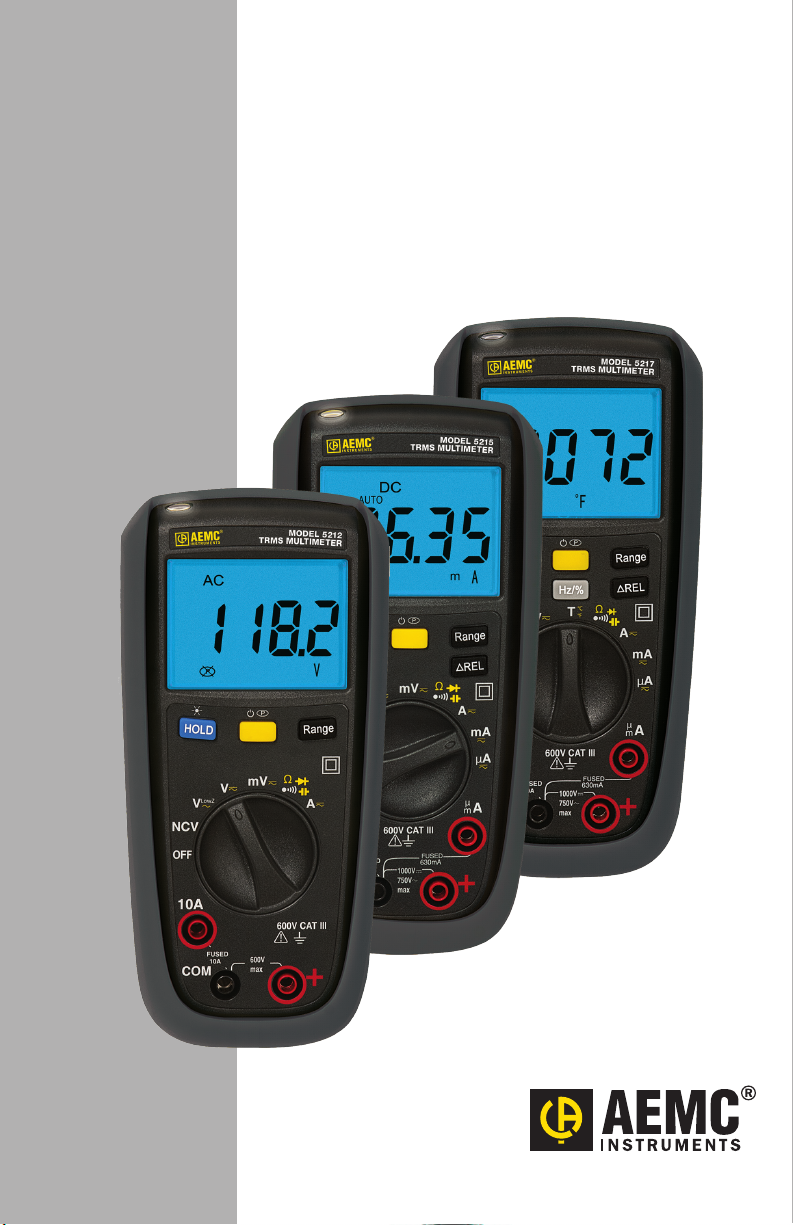
Digital Multimeter
Models 5212,
5215 & 5217
ENGLISH
User Manual
Page 2

Page 3

Copyright © Chauvin Arnoux®, Inc. d.b.a. AEMC® Instruments. All rights reserved.
No part of this documentation may be reproduced in any form or by any means (including electronic
storage and retrieval or translation into any other language) without prior agreement and written consent
from Chauvin Arnoux®, Inc., as governed by United States and International copyright laws.
Chauvin Arnoux®, Inc. d.b.a. AEMC® Instruments
15 Faraday Drive, Dover, NH 03820 USA
Tel: (800) 945-2362 or (603) 749-6434
Fax: (603) 742-2346
This documentation is provided “as is,” without warranty of any kind, expressed, implied, or otherwise.
Chauvin Arnoux®, Inc. has made every reasonable eort to ensure that this documentation is accurate;
but does not warrant the accuracy or completeness of the text, graphics, or other information contained
in this documentation. Chauvin Arnoux®, Inc. shall not be liable for any damages, special, indirect,
incidental, or inconsequential; including (but not limited to) physical, emotional, or monetary damages
due to lost revenues or lost prots that may result from the use of this documentation, whether or not the
user of the documentation has been advised of the possibility of such damages.
Chauvin Arnoux®, Inc., AEMC®, are registered trademarks of Chauvin Arnoux®, Inc.
Page 4

Statement of Compliance
Chauvin Arnoux®, Inc. d.b.a. AEMC® Instruments
certifies that this instrument has been calibrated
using standards and instruments traceable to
international standards.
We guarantee that at the time of shipping your
instrument has met its published specifications.
An N.I.S.T. traceable certificate may be
requested at the time of purchase, or obtained
by returning the instrument to our repair and
calibration facility, for a nominal charge.
The recommended calibration interval for this
instrument is 12 months and begins on the date of
receipt by the customer. For recalibration, please
use our calibration services. Refer to our repair
and calibration section at www.aemc.com.
Serial #: ________________________________
Catalog #: 2154.07/2154.08/2154.09
Model #: 5212/5215/5217
Please fill in the appropriate date as indicated:
Date Received: _________________________________
Date Calibration Due: _______________________
Chauvin Arnoux®, Inc.
d.b.a AEMC® Instruments
www.aemc.com
Page 5
Thank you for purchasing the AEMC Multimeter.
For best results from your instrument and for your safety, read the enclosed
operating instructions carefully and comply with the precautions for use. These
products must be only used by qualied and trained users.
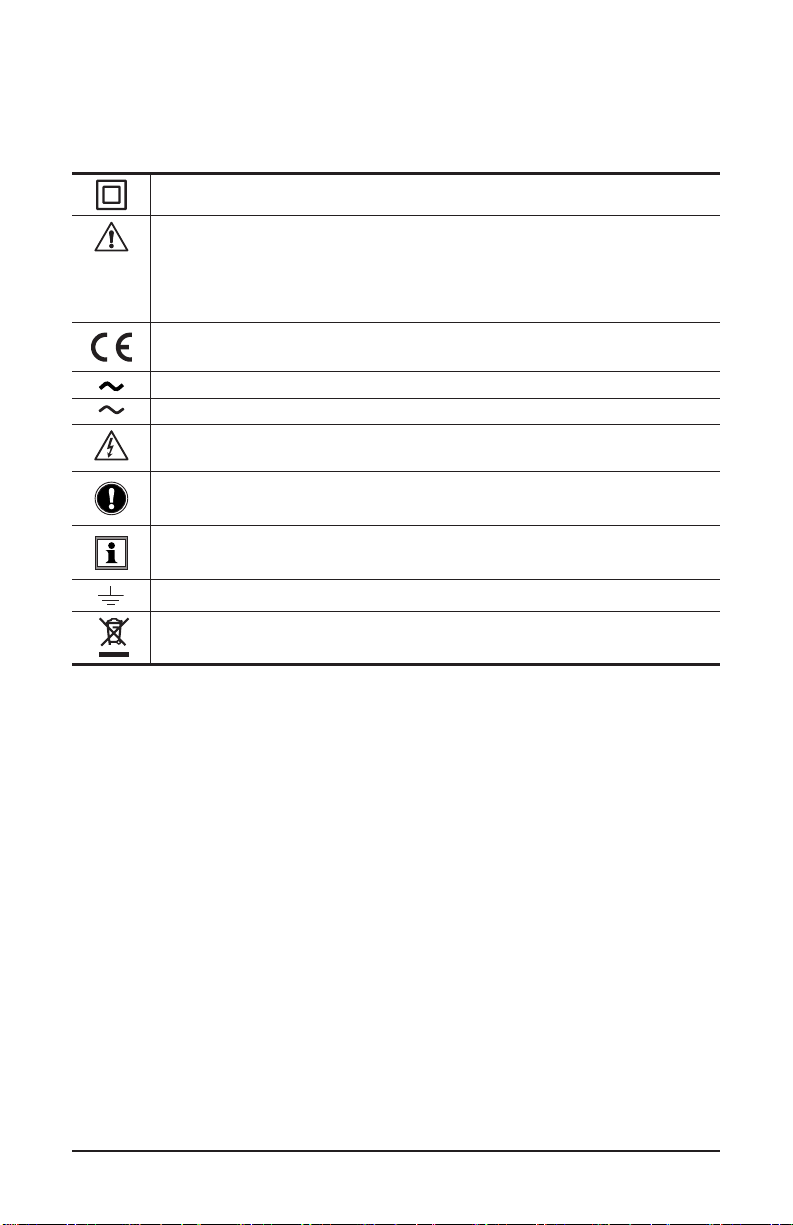
Signifies that the instrument is protected by double or reinforced insulation.
This symbol on the instrument indicates a WARNING that the operator must
refer to the user manual for instructions before operating the instrument. In
this manual, the symbol preceding instructions indicates that if the instructions
are not followed, bodily injury, installation/sample and/or product damage may
result.
Compliance with the Low Voltage & Electromagnetic Compatibility European
directives (73/23/CEE & 89/336/CEE)
AC – Alternating current
AC or DC – Alternating or direct current
Risk of electric shock. The voltage at the parts marked with this symbol may be
dangerous.
Important instructions to read and understand completely.
Important information to acknowledge.
Ground/Earth symbol
Denition of Measurement Categories (CAT)
CAT IV Measurement category IV corresponds to measurements taken at the
CAT III Measurement category III corresponds to measurements on building
CAT II Measurement category II corresponds to measurements taken on
Multimeter Models 5212/5215/5217
In conformity with WEEE 2002/96/EC
source of low-voltage installations.
Example: power feeders, counters and protection devices.
installations.
Example: distribution panel, circuit-breakers, machines or xed
industrial devices.
circuits directly connected to low-voltage installations.
Example: power supply to domestic electrical appliances and portable
tools.
1
Page 6

PRECAUTIONS FOR USE
The protection obtained by the instrument can be compromised if it is used
in a way that is not recommended by the manufacturer. Carefully read and
understand all required precautions when using this instrument.
Failure to comply with these safety instructions can create a risk of electric shock,
re, and explosion; resulting in destruction of the instrument, injury to the user,
and damage to the facility. If the instrument is used other than as specied in this
manual, the protection provided by the instrument may be impaired.
■ Before using the instrument, make sure it functions properly by measuring a
known voltage, and check continuity by short-circuiting both test leads.
■ Do not use the instrument in an explosive atmosphere or in the presence of
ammable gas or smoke.
■ Do not use the instrument on electrical networks with a rated voltage or
category higher than those listed for the instrument.
■ Respect the maximum rated voltages and currents between terminals and in
relation to ground/earth.
■ Do not use the instrument if it appears damaged, incomplete, or incorrectly
closed.
■ Before each use, check the condition of the insulation of the leads, the
instrument, and all accessories. Any insulation that appears damaged (even
partially) must be taken out of service for repair or disposal.
■ Use leads and accessories for voltage according to IEC 61010-031 and
measurement categories at least equal to those of the instrument. An
accessory with a lower category reduces the category of the combined
multimeter/accessory combination to that of the accessory.
■ Respect the environmental conditions of use listed in this manual.
■ Strictly comply with the fuse specications. Disconnect all cables before
opening the fuse access cover.
■ Do not modify the instrument or replace components using substitute parts.
Repairs and adjustments must be performed by AEMC® Instruments.
■ Replace the battery immediately if the symbol appears on the display.
Disconnect all leads before opening the battery access cover.
■ Use personal protection equipment when conditions require it.
■ Keep hands and ngers away from unused terminals.
2 Multimeter Models 5212/5215/5217
Page 7

Table of Contents
1. INTRODUCTION .............................................................................................5
1.1 Receiving Your Shipment......................................................................5
1.2 Ordering Information .............................................................................5
1.2.1 Replacement Parts ...................................................................5
1.3 Introducing the Models 5212, 5215 & 5217 ..........................................6
1.4 Front Panel ...........................................................................................8
1.5 LCD Screen ..........................................................................................9
1.6 Buttons ...............................................................................................10
1.7 Selection Dial ......................................................................................10
1.8 Terminals ............................................................................................11
2. SET UP & OPERATION .................................................................................12
2.1 Setup ..................................................................................................12
2.1.1 Installing Batteries ..................................................................12
2.1.2 Mounting .................................................................................13
2.1.3 Instrument Check ...................................................................14
2.2 Measurement Options ........................................................................14
2.2.1 Manual Range and Auto Range .............................................15
2.2.2 Display Hold ...........................................................................15
2.2.3 Max-Min Spread (Models 5215 and 5217) .............................15
2.2.4 Relative Measurement (Models 5215 and 5217) ...................16
2.3 Operation ............................................................................................16
2.3.1 Non-Contact Voltage Detection (NCV) ...................................17
2.3.2 Voltage Measurement.............................................................18
2.3.3 DC and AC Current Measurement..........................................19
2.3.4 Continuity Check ....................................................................20
2.3.5 Resistance Measurement .......................................................21
2.3.6 Diode Test ...............................................................................22
2.3.7 Capacitance Measurement.....................................................23
2.3.8 Frequency & Duty Cycle Measurement (Model 5217)............24
2.3.9 Temperature Measurement (Model 5217) ..............................24
3. SPECIFICATIONS .........................................................................................25
3.1 Reference Conditions .........................................................................25
3.2 General Specications ........................................................................25
3.3 Measurement Resolution and Accuracy .............................................26
Multimeter Models 5212/5215/5217
3
Page 8

4. MAINTENANCE ............................................................................................28
4.1 Battery Check .....................................................................................28
4.2 Cleaning..............................................................................................28
4.3 Testing and Replacing Fuses ..............................................................28
4.3.1 Testing the 10A Fuse ..............................................................28
4.3.2 Testing the 630mA Fuse .........................................................29
4.3.3 Replacing a Fuse....................................................................29
4.4 Metrological Check and Calibration ....................................................30
4.5 Technical and Sales Assistance ..........................................................30
4.6 Limited Warranty .................................................................................31
4.7 Warranty Repairs ................................................................................31
4 Multimeter Models 5212/5215/5217
Page 9

1. INTRODUCTION
1.1 Receiving Your Shipment
Upon receiving your shipment, make sure that the contents are consistent with the
packing list. Notify your distributor of any missing items. If the equipment appears
to be damaged, le a claim immediately with the carrier and notify your distributor
at once, giving a detailed description of any damage. Save the damaged packing
container to substantiate your claim.
1.2 Ordering Information
Multimeter Model 5212 ................................................................... Cat. #2154.07
Multimeter Model 5215 ................................................................... Cat. #2154.08
Multimeter Model 5217 ................................................................... Cat. #2154.09
Includes meter, soft carrying pouch, set of 2 color-coded leads (red/black), K-Thermocouple
adapter (Model 5217), two 1.5V AA batteries and a user manual.
1.2.1 Accessories
Lead - Set of 2, 5 ft (1.5m) Color-coded (Red/Black) Silicone Leads,
Test Probes & Alligator Clips {Rated 1000V CAT IV} ........................ Cat. #2152.05
MultiFix (universal mounting system) ............................................... Cat. #5000.44
1.2.2 Replacement Parts
Soft Carrying Pouch .........................................................................Cat. #2154.71
Lead - Set of 2, 5 ft (1.5m) Needle Tip Color-coded (Red/Black) w/4mm Right-angle
Plug {600V CAT IV w/shield on Needle Tip, 1000V CAT II w/o sheild}
K-Thermocouple w/4mm integrated adapter .................................... Cat. #2139.71
Fuse - Set of 5, 10A, 1000V (Fast Blow), 30kA,
0.4 x 1.2" (10 x 30mm) .....................................................................Cat. #2154.75
Fuse - Set of 5, 0.63A, 1000V (Fast Blow), 10kA,
0.25 x 1.26" (6.3 x 32mm) ................................................................Cat. #2154.76
..Cat. #2154.74
Order Accessories and Replacement Parts Directly Online
Check our Storefront at www.aemc.com for availability
Multimeter Models 5212/5215/5217
5
Page 10

1.3 Introducing the Models 5212, 5215 & 5217
The Digital Multimeter Models 5212, 5215, and 5217 measure electrical and
physical quantities, including:
■ AC and DC Voltage
■ AC and DC Current
■ Resistance and Continuity
■ Capacitance
■ Frequency and duty cycle (Model 5217)
■ Temperature (Model 5217)
The instrument can also perform continuity checks, voltage detection, and diode
testing (including forward bias voltage). Measurement features include Auto
Range mode, which enables the instrument to select the best range for the input
detected, and a Data Hold function.
The following table lists the various features respectively:
Model 5212 Model 5215 Model 5217
TRMS ● ● ●
LCD 4000 cts 6000 cts 6000 cts
NCV ● ● ●
VLowZ ● ● ●
VAC ● ● ●
VDC ● ● ●
mVAC ● ●
mVDC ● ●
AAC ● ● ●
ADC ● ● ●
mAAC ● ●
mADC ● ●
µAAC ● ●
µADC ● ●
Temperature °C & °F ●
Resistance ● ● ●
Diode test ● ● ●
Continuity ● ● ●
Capacitance ● ● ●
HOLD ● ● ●
Backlight ● ● ●
Flashlight ● ● ●
6 Multimeter Models 5212/5215/5217
Page 11

Model 5212 Model 5215 Model 5217
Auto Range ● ● ●
Max-Min ● ●
Frequency (Hz) and
Duty Cycle
Relative Measurement ● ●
Sleep Mode ● ● ●
●
Multimeter Models 5212/5215/5217
7
Page 12

1.4 Front Panel
1
2
3
4
5
6
7
8
HOLD
Max-Min
NCV
OFF
10A
COM
FUSED
10A
Hz/%
600V CAT III
1000V
750V~
max
FUSED
630mA
Range
REL
9
10
11
µ
A
m
12
13
Figure 2-1 (Model 5217 Shown) aaaaa
The instrument front panel consists primarily of an LCD display, a rotary mode
selection dial, function buttons, and input terminals. Dierent instrument models
provide dierent combinations of buttons, modes, and terminals.
1 "Flashlight" LED 8 Common input terminal
2 LCD display 9 Range button
Function (yellow) button
3
Sleep mode enable/disable
Relative Measurement button
10
(Models 5215/5217)
HOLD button
Short press: Holds measurement
4
Long (>2s) press: turns on back-
Frequency/duty cycle button
11
(Model 5217)
light/ashlight
Maximum/Minimum button
5
(Models 5215 and 5217)
µ/mA current input terminal
12
(Models 5215/5217)
6 Measurement selection dial 13 Voltage input terminal
7 10A current input terminal
8 Multimeter Models 5212/5215/5217
Page 13

1.5 LCD Screen
1
2
101112131415
3 4 5 6
Figure 2-2
987
In the center of the front panel is the LCD screen. In addition to displaying measurement results, the LCD includes a number of indicator symbols.
1 Relative mode 9 Duty cycle percentage
2 Auto ranging enabled 10
3 Low Battery indicator 11 Decimal prex (mega or kilo)
Sleep mode (auto-shutdown)
4
enabled
5 Max, Min, or Max minus Min indicator 13 Diode test selected
6 Fahrenheit or Celsius indicator 14 AC or DC indicator
Decimal prex
7
(nano, micro, or milli)
Amps or volts indicator;
8
Capacitance (Farads) indicator
Measurement
(resistance or frequency)
12 Continuity test selected
15 Display Hold enabled
Multimeter Models 5212/5215/5217
9
Page 14

1.6 Buttons
Below the LCD is a set of up to six buttons (model dependent).
Figure 2-3 (Model 5217) xxxx
■ HOLD freezes the measurement display (see § 2.2.2). A long press (>2 seconds)
turns ON the "ashlight" on the top of the instrument, and the LCD backlight.
■ (Yellow button) performs several tasks, depending on the instrument
mode. These include:
- Enable and disable Sleep mode (§ 2.1.1.1)
- Toggle between AC and DC in current and voltage measurements (§ 2.3.2
and 2.3.3)
- Toggle between continuity/ resistance/ diode/capacitance measurement
(§ 2.3.4 through 2.3.6)
- Toggle between °C and °F for temperature measurements on Model 5217
(§ 2.3.9)
■ Range enables/disables auto ranging (§ 2.2.1).
■ Max-Min (Models 5215 and 5217) enables Max-Min mode (§ 2.2.3).
■ ΔREL (Models 5215 and 5217) enables relative measurement mode (§ 2.2.4).
■ Hz% (Model 5217) enables frequency and duty cycle measurement (§ 2.3.8).
1.7 Selection Dial
The rotary selection dial determines the type of measurement to be made.
NCV
OFF
µ
A
10A
Figure 2-4 (Model 5217) xxxx
10 Multimeter Models 5212/5215/5217
m
Page 15

OFF Turns the instrument OFF Temperature (Model 5217)
NCV
Non-Contact Voltage
detection
Continuity/Resistance/Diode
test/Capacitance/Fuse check
Voltage with instrument
set to low impedance
Amps
voltage mode
Voltage with instrument set to
normal voltage mode
millivolts
(Models 5212 and 5215)
milliamps
(Models 5215 and 5217)
microamps
(Models 5215 and 5217)
1.8 Terminals
The instrument includes three (Model 5212) or four (Models 5215 and 5217)
input terminals.
µ
A
10A
600V CAT III
m
1000V
750V~
max
FUSED
630mA
COM
FUSED
10A
Figure 2-5 (Models 5215 and 5217)
■ 10A is used for measuring AC and DC current up to 10A, and (Model 5217)
current frequency/duty cycle. For the Model 5212 this terminal is used for all
current measurements. For the Models 5215 and 5217 this is used for
(amp) measurements.
(Models 5215 and 5217) is used for AC and DC milliamp and microamp
■
current measurements up to 600mA.
■ COM (Common) is the “return” terminal used for all measurements.
■ + is used for measuring voltage, capacitance, and resistance; for checking
circuit continuity; and for checking diodes. For the Model 5217, this terminal is
also used for measuring temperature and voltage frequency/duty cycle.
Multimeter Models 5212/5215/5217
11
Page 16

2. SET UP & OPERATION
2.1 Setup
The instrument requires a few simple setup steps before use. This includes:
■ Install the batteries and perform a battery check.
■ Perform a quick instrument check.
■ Select a mounting format (at or hand-held, magnetic mount, stand).
2.1.1 Installing Batteries
The instrument uses two AA batteries. To install the batteries:
1. Ensure all leads are disconnected from the instrument and the circuit.
2. Remove the protective rubber shock-proof housing from the instrument.
3. Using a screwdriver, remove the two battery cover screws on the back.
4. Lift the instrument stand, and then gently pull on the stand to separate
the battery cover from the instrument.
5. Place the batteries in the casing. Be sure to position each with the
correct polarity.
6. Replace the battery cover, screws, and protective housing.
7. Turn ON the instrument by selecting any dial setting and check that it
powers up correctly. Then check the LCD to see whether or not the Low
Battery indicator is displayed. If so, replace the batteries.
Figure 3-1
12 Multimeter Models 5212/5215/5217
Page 17

2.1.1.1 Sleep Mode
To extend battery life, the instrument includes a Sleep mode feature.
In Sleep mode, the LCD turns OFF after 30 minutes of inactivity. Pressing the
(yellow button) restores the LCD. When Sleep mode is enabled, the P
symbol appears.
To disable the Sleep mode feature, press and hold down while turning the
instrument ON. (Sleep mode will be re-enabled the next time you turn the instrument ON.)
2.1.2 Mounting
The instrument can be mounted three dierent ways:
■ Stand: The instrument includes a pull-out stand. When this stand is extended,
the instrument can be placed on a horizontal surface for viewing in an upright
position.
Figure 3-2
■ Mounting Slot: On the back of the instrument is a slot that can be slid over a
screw head or other mounting point. This lets you mount the instrument to a wall
or other permanent location.
■ Magnet Mount: The removable protective housing includes a set of molded-
in magnets located near the top. These allow the instrument to be axed onto
a magnetic surface.
Multimeter Models 5212/5215/5217
13
Page 18

2.1.3 Instrument Check
Before using the instrument for the rst time, perform a quick series of steps to
ensure it is working properly. We also recommend performing this procedure
whenever you operate the instrument after a prolonged period of inactivity (a
week or longer).
1. Ensure all leads are disconnected from the instrument and the circuit.
2. Turn the instrument ON. Check the startup screen to ensure all symbols
and indicators display. (Due to the short duration the startup screen
appears, you may need to turn the instrument ON and OFF more than
once to check every part of the screen.
3. Turn the rotary dial to the Continuity setting. The LCD should
display the symbol OL, indicating an overload condition.
4. With the dial still on , insert the red test lead into the + (voltage)
terminal and the black test lead into the COM terminal. Touch the leads
together; the beeper should sound, and after a few moments a reading
close to 000.0 should appear on the LCD.
5. Turn the dial to a voltage setting (for example ), select AC or DC
by pressing , and touch the leads to a known voltage (such as a
battery or AC electrical outlet) to ensure the reading is accurate.
2.2 Measurement Options
The instrument includes several features that enhance its measurement and
display capabilities, including:
■ Manual and Auto Range let you set the measurement range yourself
or enable the instrument to do it.
■ Display HOLD lets you “freeze” a measurement displayed on the
screen.
■ Maximum/Minimum mode displays the maximum and minimum
measurements and the dierence between them (Models 5215 and
5217).
■ Relative Measurement denes a measurement value against which
subsequent measurements will be compared (Models 5215 and 5217).
14 Multimeter Models 5212/5215/5217
Page 19

2.2.1 Manual Range and Auto Range
The instrument features both manual range and Auto Range options. Auto Range
enables the instrument to automatically select the best measurement range for
the detected resistance, voltage, current, or capacitance input. This allows you to
have the best resolution without manually resetting the range.
By default, the instrument starts in Auto Range mode, as indicated by the AUTO
indicator on the LCD. To enable manual ranging, press the Range button. Each
subsequent press of this button increases the measurement range by one order
of magnitude (10x). When the highest range is reached, pressing this button
returns to the lowest range.
To exit manual ranging, press and hold down the Range button until AUTO is
displayed on the LCD.
2.2.2 Display Hold
To freeze a measurement displayed on the LCD, press the HOLD button once.
The measurement will remain on the screen until you press the HOLD button
a second time to resume normal measurement display. When display hold is
enabled, the
symbol appears on the LCD.
2.2.3 Max-Min Spread (Models 5215 and 5217)
By default, the instrument displays measurements continuously in real-time. You
can instead have the instrument display only the minimum and maximum values
of a measurement session. To do this, turn the instrument dial to the desired
measurement type, and proceed as follows:
1. Press the Max-Min button. This initiates Max-Min mode, with the
maximum value displayed for the measurement session. (The MAX
symbol appears.) This value will remain on the screen until a higher
value is measured.
2. Press the Max-Min button a second time to view the minimum value
measured during this session. (The MIN symbol appears.) As with the
maximum, the minimum value remains on the LCD until a lower value is
measured.
3. Press the Max-Min button a third time to display the dierence (spread)
obtained by subtracting the maximum from the minimum. (The MAX-MIN
symbol appears.)
4. To exit this mode, press and hold down the Max-Min button for longer
than 2 seconds.
NOTE: Auto Range is disabled in Max-Min mode.
Multimeter Models 5212/5215/5217
15
Page 20

2.2.4 Relative Measurement (Models 5215 and 5217)
The instrument lets you dene a measurement against which other measurements can be compared. The LCD will then display the dierence between the
present measurement and the dened “reference” measurement. This feature is
available for all measurement types except frequency, duty cycle, NCV, diode,
and continuity.
To set the reference measurement, turn the instrument dial to the desired
measurement type, and proceed as follows:
1. Touch the test leads to the circuit.
2. When the desired measurement is displayed, press the ΔREL button.
This stores the measured value as the reference, and activates relative
measurement mode. (The ΔREL symbol appears on the LCD.)
3. As you take additional measurements, the LCD displays the dierence
between the real-time measurement and the reference measurement.
4. To exit relative measurement mode, press ΔREL until the ΔREL symbol
disappears.
NOTE: Auto Range is disabled in relative measurement mode.
2.3 Operation
All Model 5200 series instruments can perform the following:
■ Voltage measurement (including low impedance voltage via the
setting)
■ Current measurement
■ Capacitance measurement
■ Resistance measurement
■ Diode test (including measuring forward bias voltage and polarity
detection)
■ Continuity check
■ Non-contact voltage detection
In addition, the Model 5217 provides the following measurements:
■ Frequency and duty cycle
■ Temperature
WARNING
Be sure to carefully observe all safety precautions when testing
components, especially when working with unknown currents or voltages.
16 Multimeter Models 5212/5215/5217
Page 21

2.3.1 Non-Contact Voltage Detection (NCV)
The instrument can detect whether or not AC voltage is present in a circuit
without making physical contact. Note that the instrument can only detect AC live
voltage referenced to the ground.
WARNING
Never touch a circuit based solely on whether or not NCV detects
voltage. Detection may not occur if:
■ The instrument is held too far away from the conductor under test
■ The electric eld is weak
■ The conductor under test is shielded
To enable voltage detection:
1. Turn the dial to NCV.
2. While holding the instrument, point it towards the conductor under
measurement and approach the conductor with the top of the instrument
3. If no AC live voltage is detected, the letters EF (Electric Field) appear
on the LCD. If AC live voltage is detected, up to four dashes appear on
the LCD, the beepers sounds, and the backlight blinks red. The number
of dashes displayed, and the speed with which the backlight blinks and
buzzer beeps, depends on how close the instrument is held to the live
conductor. The closer the conductor, the more dashes are displayed and
the faster the blinking/beeping.
Multimeter Models 5212/5215/5217
HOLD
Max-Min
NCV
OFF
10A
COM
Range
REL
Hz/%
µ
A
m
600V CAT III
FUSED
FUSED
630mA
10A
1000V
750V~
max
Figure 3-1
17
Page 22

2.3.2 Voltage Measurement
The instrument provides three settings for measuring voltage:
■ lowers the instrument’s input impedance to 500kΩ to help prevent “ghost”
voltage from aecting the measurement. (Standard input impedance can be in the
10 to 11MΩ range, depending on the voltage measurement range selected.)
■ measures volts
■ measures millivolts (Models 5212 and 5215)
To take a voltage measurement:
1. Connect the red test lead to the + terminal and the black test lead to
COM.
2. Turn the rotary dial to the desired voltage setting ( , , or ).
Hz/%
600V CAT III
1000V
750V~
max
Range
REL
µ
A
m
FUSED
630mA
NCV
OFF
HOLD
Max-Min
10A
COM
FUSED
10A
Figure 3-2
3. Connect the probe tips to the circuit under test.
4. Press to toggle back and forth between AC and DC
measurements. (Note that VDC is not available in mode.)
NOTE: When the Model 5212 or Model 5215 is set to , input above 400mV
(Model 5212) or 600mV (Model 5215) displays the symbol on the LCD,
indicating an overload condition.
18 Multimeter Models 5212/5215/5217
Page 23

2.3.3 DC and AC Current Measurement
All Model 5200 series instruments provide the setting for measuring current.
The Models 5215 and 5217 also include the settings (milliamps) and
(microamps).
By default, the instrument is in DC mode.
To measure current:
1. Connect the black test lead to the COM terminal, and the red test lead
as follows:
- For measuring amps, connect to the terminal labeled 10A.
- For measuring milliamps or microamps on the Models 5215 and
5217, connect to the terminal labeled .
HOLD
Max-Min
NCV
OFF
10A
COM
Range
REL
Hz/%
µ
A
m
600V CAT III
FUSED
FUSED
630mA
10A
1000V
750V~
max
HOLD
Max-Min
NCV
OFF
10A
COM
Range
REL
Hz/%
µ
A
m
600V CAT III
FUSED
FUSED
630mA
10A
1000V
750V~
max
Amps Milliamps/Microamps
Figure 3-3
2. Turn the dial to the desired current setting ( , , or ).
3. Connect the probe tips to the circuit under test.
4. Press the yellow button to toggle back and forth between AC and
DC measurements.
NOTE: If current is above 10A, an alarm sounds and the instrument’s fuse may
blow.
Multimeter Models 5212/5215/5217
19
Page 24

2.3.4 Continuity Check
The instrument can perform a quick continuity check. This can help determine
whether or not a circuit is complete.
1. Ensure that the circuit to be tested has no voltage running through it.
An NCV test can help determine whether or not the circuit is live (see §
2.3.1).
2. Connect the red test lead to the + terminal and the black test lead to the
COM terminal.
3. Turn the dial to .
4. Touch the probes to the desired points in the circuit under test. If there
is continuity, the circuit’s resistance is displayed on the LCD. If this
resistance is under 50Ω, the beeper also sounds, indicating a potential
short circuit.
NOTE: If there is no continuity (the resistance is above 600Ω), the LCD displays
, indicating an open circuit or high resistance. symbol on the LCD, indicating
an overload condition.
20 Multimeter Models 5212/5215/5217
Page 25

2.3.5 Resistance Measurement
To measure resistance, perform the following steps:
1. Ensure that the circuit to be tested has no voltage running through it (see
§ 2.3.1).
2. Connect the red test lead to the + terminal and the black test lead to the
COM terminal.
3. Turn the dial to .
4. Press the yellow button once. The symbol MΩ appears on the
LCD, indicating the instrument is in resistance measurement mode.
5. Touch the probes to the desired points in the circuit under test. The
resistance measurement appears on the LCD. If the resistance between
the two points is above 60MΩ (or 40MΩ in the Model 5212), the LCD
displays the symbol.
NCV
OFF
Multimeter Models 5212/5215/5217
HOLD
Max-Min
10A
COM
FUSED
10A
Hz/%
600V CAT III
1000V
750V~
max
Range
REL
µ
A
m
FUSED
630mA
Figure 3-4
< 50
21
Page 26

2.3.6 Diode Test
The instrument can measure the forward bias voltage of a diode, and also determine the diode’s polarity.
1. Ensure that the circuit to be tested has no voltage running through it (see
§ 2.3.1).
2. Connect the red test lead to the + terminal and the black test lead to the
COM terminal.
3. Turn the dial to .
4. Press the yellow button twice. The symbol appears on the
LCD, indicating the instrument is in diode testing mode.
5. Touch the red test probe to the anode side of the diode under test, and
black test probe to the cathode side. The diode’s forward bias voltage is
displayed on the screen.
6. If the polarity of the test leads is reversed with diode polarity (or if the
forward bias voltage is above 3V) the symbol appears on the LCD.
This can help identify the anode and cathode of the diode.
2x
< 50
Hz/%
Range
REL
µ
A
m
FUSED
630mA
1000V
750V~
max
HOLD
Max-Min
NCV
OFF
10A
COM
FUSED
10A
600V CAT III
Figure 3-5
22 Multimeter Models 5212/5215/5217
Page 27

2.3.7 Capacitance Measurement
To measure capacitance:
1. Ensure that the circuit to be tested has no voltage running through it
(see § 2.3.1).
2. Connect the red test lead to the + terminal and the black test lead to the
COM terminal.
3. Turn the dial to .
4. Press the yellow button three times. The nF symbol appears on
the LCD, indicating the instrument is in capacitance measurement mode.
5. Touch the probes to the capacitor leads. After a few moments, the
measurement will stabilize and display on the LCD. (This may require 15
seconds or more for measurements in the 100mF range.)
3x
HOLD
Max-Min
NCV
OFF
10A
Multimeter Models 5212/5215/5217
COM
FUSED
10A
Hz/%
600V CAT III
1000V
750V~
max
Range
REL
µ
A
m
FUSED
630mA
Figure 3-6
23
Page 28

2.3.8 Frequency & Duty Cycle Measurement (Model 5217)
You can measure frequency while performing an AC voltage or current measurement. The instrument can measure the duty cycle of a square signal.
1. While in any AC current or voltage measurement mode, press the Hz/%
button. This displays the frequency of the AC signal under measurement.
(The symbol Hz appears on the LCD.)
2. Press Hz/% a second time to display the signal’s percent of duty cycle.
3. Press Hz/% again to return to normal current/voltage measurement.
(The symbol AC reappears on the LCD.)
2.3.9 Temperature Measurement (Model 5217)
The instrument includes an internal temperature sensor that allows it to display
ambient temperature above 0°C without any input. An optional external K type
thermocouple (Cat. #2139.71) is available as an accessory.
WARNING
Do not measure temperature on a live circuit.
■ Ensure that the circuit to be tested has no voltage running through it
(see § 2.3.1).
■ Turn the rotary dial to . The instrument displays the ambient
temperature as measured by its internal temperature sensor.
■ Plug the thermocouple’s positive lead into the + terminal and the
negative lead into the COM terminal.
■ Touch the thermocouple tip to the object under measurement.
■ Allow one minute for thermal stabilization.
■ Press the yellow button to toggle between Celsius (°C) and
Fahrenheit (°F).
■ If the measured temperature exceeds 1300°C (2372°F) the LCD
displays the symbol.
24 Multimeter Models 5212/5215/5217
Page 29

3. SPECIFICATIONS
3.1 Reference Conditions
Inuencing Parameters Reference Conditions
Ambient temperature 23°C ± 3° (73°F ± 5°)
Relative humidity 45 to 75%
AC frequency 60Hz ± 15Hz
Magnetic eld 0A/m AC
Electric eld 0V/m AC
Electrical purity
3.2 General Specications
In DC: AC < 0.1% of the DC signal
In AC: DC < 0.1% of the AC signal
Standard
Display Digital LCD:
Temperature Operating: -4°F to 120°F (-20° to 50°C)
Temperature coecient
%RH (non-condensing)
Operating Altitude
Electromagnetic compatibility
Battery type
Battery life
Size (H x W x L)
Weight
Conformity
Mechanical Conformity Drop test 1m: IEC 68-2-32
Test Probes Conformity
Fuses • F1: Fast Fuse 630mA, 1000V, 10kA, size: 6.3
IP Rating
600V CAT III IEC61010-1, IEC61010-2-033
• Models 5215 and 5217: 6000 count updates
3 times/s
• Model 5212: 4000 count updates 3 times/s
Storage: -22°F to 130°F (-30° to 55°C)
150ppm (for T °C function 0.15%/°C)
< 90% RH (up to 45°C (113°F))
0 to 2000m (approximately 6500’)
EN 61326-1, EN 61326-2-2
2 AA, NEDA 15A, IEC LR6
Alkaline: typically 500 hours (approx)
6.7 x 3.1 x 2" (170 x 80 x 50mm)
(with holster)
11.2 oz (320g approx)
CE Marked
Shock 0.5J (IK04): IEC 68-2-27
IEC 61010-031
x 32mm (approximately 0.26 x 1.26")
• F2: Fuse 10A, 1000V, 30kA, size: 10 x 38mm
(approximately 0.39 x 1.5”)
IP54
Multimeter Models 5212/5215/5217
25
Page 30

3.3 Measurement Resolution and Accuracy
In the following table, accuracy is expressed as
± (x% + y)
where x% = the percentage of the reading and y = a number of counts
(measured units). For example, the table below indicates that for measuring AC
voltage the accuracy is 0.5% +4cts.
Accuracy values assume operation within the reference conditions listed in § 3.1.
Measurement
V
AC
V
DC
mV
AC
mV
DC
A
AC
ADC
mAAC
mADC
µAAC
µADC
Model
5212
Range
Model
5215
Model
5217
Res.
Model
5212
Accuracy
Model
5215
4.000V 6.000V 6.000V 0.001V
40.00V 60.00V 60.00V 0.01V
400.0V 600.0V 600.0V 0.1V
0.5%+4cts
600V 750V 750V 1V
4.000V 6.000V 0.001V
40.00V 60.00V 0.01V
0.2%+2cts
400.0V 600.0V 0.1V
600V 1000V 1V 0.5%+2cts
40.00mV 60.00mV
400.0mV 600.0mV 0.1mV 1%+4cts
40.00mV 60.00mV 0.01mV 1%+5cts
N/A
0.01mV 1%+6cts
400.0mV 600.0mV 0.1mV 0.2%+2cts
4.000A 6.000A 0.001A 1%+5cts
10.00A 0.01A 0.5%+5cts
4.000A 6.000A 0.001A 1%+5cts
10.00A 0.01A 0.5%+5cts
60.00mA 0.01mA
600.0mA 0.1mA
60.00mA 0.01mA
N/A
600.0mA 0.1mA
600.0µA 0.1µA
N/A
6000µA 1µA
600.0µA 0.1µA
6000µA 1µA
Model
5217
0.2%+2cts
N/A
0.5%+5cts
0.5%+3cts
1%+5cts
0.5%+5cts
26 Multimeter Models 5212/5215/5217
Page 31

Range
Measurement
Resistance
Diode test 3.000V 0.001V 10%
Capacitance
Model
5212
400.0Ω 600.0Ω 0.1Ω
4.000kΩ 6.000kΩ 0.001kΩ
40.00kΩ 60.00kΩ 0.01kΩ
400.0kΩ 600.0kΩ 0.1kΩ
4.000MΩ
40.00MΩ
Model
5215
1.000nF 0.001nF 10%+10cts
10.00nF 0.01nF 5%+5cts
100.0nF 0.1nF
1.000µF 0.001µF
10.00µF 0.01µF
100.0µF 0.1µF
1.000mF 0.001mF
10.00mF 0.01mF
100.0mF 0.1mF
Model
5217
6.000MΩ
60.00MΩ
Res.
0.001MΩ 1%+5cts
0.01MΩ 3%+5cts
Model
5212
0.5%+5cts
Model 5217 Only
Accuracy
Model
5215
2%+5cts
5%+5cts
Model
5217
Measurement Range Res. Accuracy
50°C to 1300°C
Temperature °C/°F
K-type thermocouple
Frequency
Duty cycle 0.1% to 99.9% 0.1 approximately 1%
Specications are subject to change without notice
Multimeter Models 5212/5215/5217
(122°F to 2372°F)
0°C to 50°C (32°F to 122°F) 0.1°C (0.2°F) (±5.4°F)
-55°C to 0°C (-67°F to 32°F) 0.1°C (0.2°F) (9%+3.6°F)
10.00Hz 0.01Hz
1.000kHz 1Hz
0.1°C (0.2°F) (2%+1.8°F)
1%+3cts100.0Hz 0.1Hz
27
Page 32

4. MAINTENANCE
WARNING
Instrument repair or replacement of parts must be performed by the
factory. Any non-approved repair or other work, such as replacing an
original part with a substitute, can severely compromise safety and will
void the warranty.
4.1 Battery Check
Before each use, turn ON the instrument and check the LCD to see whether
or not the Low Battery indicator is displayed. If so, replace the batteries as
instructed in § 2.1.
4.2 Cleaning
Periodically wipe the case with a damp cloth and mild detergent. Do not use
abrasives or solvents. Dirt or moisture in the terminals can aect the readings.
Completely dry the instrument after cleaning and before each use.
4.3 Testing and Replacing Fuses
The instrument ships with two fuses, a 10A fuse (installed behind the 10A terminal) and a 630mA “fast” fuse (installed behind the terminal). If the fast fuse
is blown the terminal is inactive; if the 10A fuse is blown the 10A terminal
is inactive. (Other functions will operate normally even with one or both fuses
blown.)
4.3.1 Testing the 10A Fuse
1. Turn the rotary dial to (Continuity test).
2. Plug one test lead into the + terminal.
3. Plug the other test lead into the 10A terminal.
4. Touch the tips of the two leads together. The buzzer beeps, and a
reading appears on the LCD. A reading between 0 and 000.2Ω indicates
the fuse is good. If appears on the LCD, replace the fuse (see §
4.3.3).
28 Multimeter Models 5212/5215/5217
Page 33

4.3.2 Testing the 630mA Fuse
1. Turn the rotary dial to .
2. Press the yellow button to enter auto ranging mode.
3. Plug one test lead into the + terminal.
4. Plug the other test lead into the terminal.
5. Touch the tips of the two leads together. A reading of around 6 to 7Ω
indicates the fuse is good. If appears on the LCD, replace the fuse
(see § 4.3.3).
4.3.3 Replacing a Fuse
WARNING
Only use 10A and 630mA fuses in the instrument, as specied in § 3.2.
1. Remove the protective housing from the instrument.
2. Using a screwdriver, remove the two battery cover screws on the back.
3. Lift the instrument stand, and then gently pull on the stand to separate
the battery cover from the instrument.
4. Locate the fuses (Figure 15). Carefully remove the fuse to be replaced,
using a athead screwdriver or similar implement if necessary.
5. Insert the replacement fuse.
6. Replace the battery cover, screws, and protective cover.
Multimeter Models 5212/5215/5217
Figure 4-1
29
Page 34

4.4 Metrological Check and Calibration
To ensure that your instrument meets factory specications, we recommend that
it be scheduled to be shipped to our factory Service Center at one-year intervals
for recalibration, or as required by other standards or internal procedures.
Note for Calibration Laboratories and Facilities: The Models 5212, 5215,
and 5217 include onboard rmware enabling each instrument to be calibrated by
connecting the inputs to a calibrator and pressing the front panel push buttons.
This information is only released to authorized personnel or facilities. Contact
AEMC® Instruments for these calibration procedures.
For Instrument Repair and Calibration:
You must contact our Service Center for a Customer Service Authorization
Number (CSA#). This will ensure that when your instrument arrives, it will be
tracked and processed promptly. Please write the CSA# on the outside of the
shipping container. If the instrument is returned for calibration, we need to know if
you want a standard calibration or a calibration traceable to N.I.S.T. (this includes
a calibration certicate plus recorded calibration data).
Ship To: Chauvin Arnoux®, Inc. d.b.a. AEMC® Instruments
15 Faraday Drive
Dover, NH 03820 USA
Phone: (800) 945-2362 (Ext. 360)
(603) 749-6434 (Ext. 360)
Fax: (603) 742-2346 or (603) 749-6309
E-mail: repair@aemc.com
(Or contact your authorized distributor)
Costs for repair, standard calibration, and calibration traceable to N.I.S.T. are
available.
NOTE: You must obtain a CSA# before returning any instrument.
4.5 Technical and Sales Assistance
If you are experiencing any technical problems, or require any assistance with
the proper operation or application of your instrument, please call, mail, fax or
e-mail our technical support team:
Chauvin Arnoux®, Inc. d.b.a. AEMC® Instruments
200 Foxborough Boulevard
Foxborough, MA 02035 USA
Phone: (800) 343-1391
(508) 698-2115
Fax: (508) 698-2118
E-mail: techsupport@aemc.com
www.aemc.com
NOTE: Do not ship Instruments to our Foxborough, MA address.
30 Multimeter Models 5212/5215/5217
Page 35

4.6 Limited Warranty
The Models 5212, 5215 & 5217 are warranted to the owner for a period of three
years from the date of original purchase against defects in manufacture. This
limited warranty is given by AEMC® Instruments, not by the distributor from
whom it was purchased. This warranty is void if the unit has been tampered with,
abused or if the defect is related to service not performed by AEMC® Instruments.
Full warranty coverage and product registration is available on our website at
www.aemc.com/warranty.html.
Please print the online Warranty Coverage Information for your records.
What AEMC® Instruments will do:
If a malfunction occurs within the one-year period, you may return the instrument
to us for repair, provided we have your warranty registration information on le or
a proof of purchase. AEMC® Instruments will, at its option, repair or replace the
faulty material.
REGISTER ONLINE AT: www.aemc.com
4.7 Warranty Repairs
What you must do to return an Instrument for Warranty Repair:
First, request a Customer Service Authorization Number (CSA#) by phone or by
fax from our Service Department (see address below), then return the instrument
along with the signed CSA Form. Please write the CSA# on the outside of the
shipping container. Return the instrument, postage or shipment pre-paid to:
Ship To: Chauvin Arnoux®, Inc. d.b.a. AEMC® Instruments
15 Faraday Drive
Dover, NH 03820 USA
Phone: (800) 945-2362 (Ext. 360)
(603) 749-6434 (Ext. 360)
Fax: (603) 742-2346 or (603) 749-6309
E-mail: repair@aemc.com
Caution: To protect yourself against in-transit loss, we recommend you insure
your returned material.
NOTE: You must obtain a CSA# before returning any instrument.
Multimeter Models 5212/5215/5217
31
Page 36

04/16
99-MAN 100419 v3
15 Faraday Drive • Dover, NH 03820 USA • Phone: (603) 749-6434 • Fax: (603) 742-2346
Chauvin Arnoux®, Inc. d.b.a. AEMC® Instruments
www.aemc.com
 Loading...