

Page 1
CLAMP-ON GROUND
RESISTANCE TESTER
Models 3711 & 3731
Measure down to 0.1Ω with resolution of 0.01Ω
Fast settling time (approximately one second)
High immunity to electrical noise for work around
transmission towers and substations
Extended battery life over 1000 tests (Auto-Off)
Rugged jaw construction withstands heavy
outdoor usage
Smooth jaw matting surfaces easily cleaned to
maintain reading accordingly
US Patent Number 362,639
Page 2
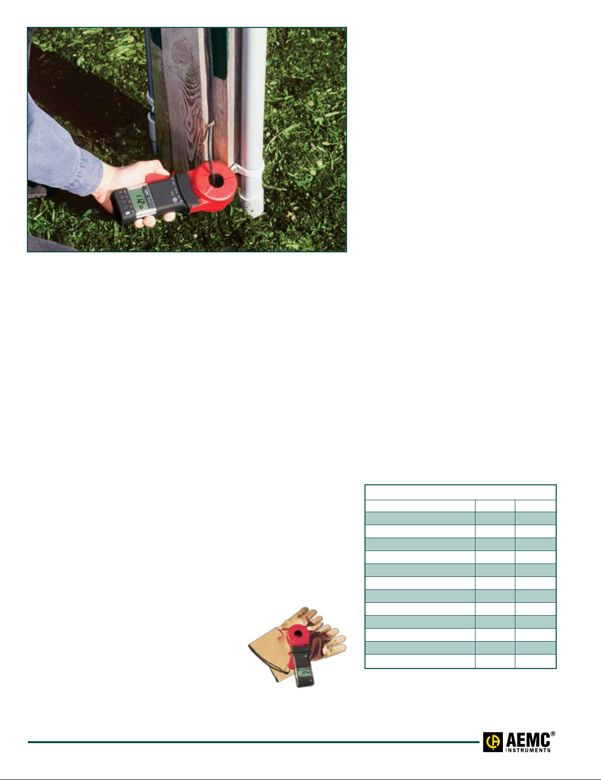
Model 3731 performing a ground rod resistance check.
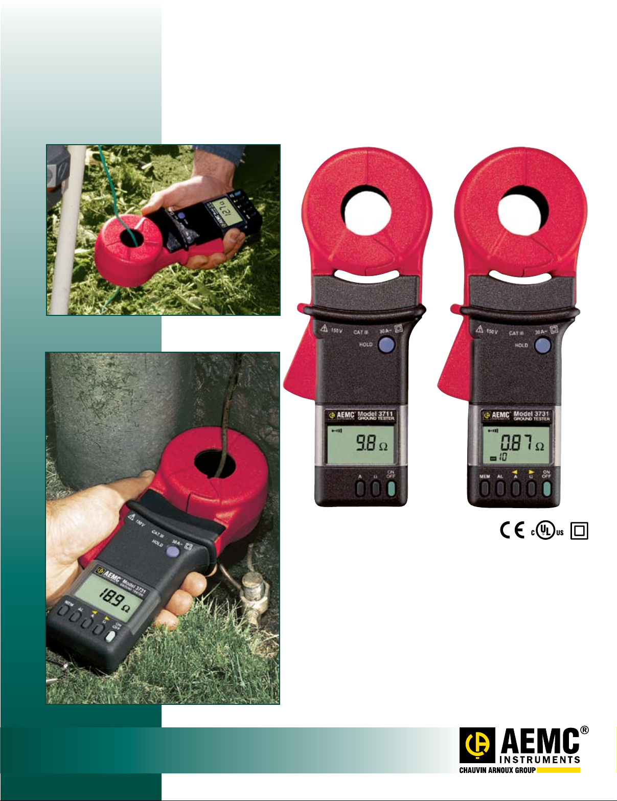
The Models 3711 and 3731 mea sure ground rod and grid resistance
in any environment without the use of auxiliary ground rods. Clamp-on
ground resistance testers are used on multi- grounded systems
without disconnecting the ground under test. The Models 3711 and
3731 simply clamp around the ground conductor or rod and measures
the resistance to ground fast and accurately.
By performing measurements on installed ground systems, the user
also verifies the quality of the grounding connections and bonds.
Resistance and continuity of grounding loops around pads and
buildings may also be measured.
Both models include a current measurement function. The probe’s
high sensitivity enables measurement of leakage current flowing to
ground or circulating in ground loops down to 1mA as well as neutral
and phase currents to 30Arms. This feature provides additional information, which is vital in distribution ground networks carrying higher
levels of noise and harmonics, that affect power quality.
The Model 3731 offers an alarm function and a memory (logging)
function. In the alarm mode, the probe will audibly and visually indicate
readings beyond set point. The user may also have the alarm initiated
above or below the set point. This alarm feature permits quick field
checks where “pass” or “fail” readings will suffice.
applications
Measure electrical ground rod and grid resistance
Use on multi-grounded systems without
disconnecting the ground rod under test
Measure resistance and continuity of
grounding loops around pads and buildings
Measure leakage current flowing to ground or
circulating in ground systems
Conduct field surveys and retrieve and analyze readings at a later time
Use on cell towers and telecommunication sites
Use on pools, spas and other consumer installations
Features
Simple and fast clamp-on operation —
no leads, no auxiliary rods or spacing
requirements
Direct reading of ground resistance
from 0.1Ω to 1200Ω
Direct reading of continuity and ground
loop resistance
Direct reading of ground leakage or
phase current from 1mA to 30Arms
Jaw design with large 1.25" (32mm)
window — accommodates up to
1000kcmil cables
Auto-Off for power management
Alarm function with adjustable set
point and buzzer for quick field checks
(Model 3731)
Memory function to store 99 field
measurements for later retrieval and
analysis (Model 3731)
Meets EN 61010, Cat. III
CE Mark and UL approved and double
insulated
Rugged Lexan® head and body
construction resists breakage
Instrument’s a larm settings and stored
memory information saved during
shutdown (Model 3731)
Patented design
FUNCTIONS & FEATURES
3711 3731
Ohms Range 3 3
Arms Range 3 3
Hold Function 3 3
Self Test 3 3
Auto-Off 3 3
Battery Life Indicator 3 3
Noise Indicator 3 3
Open Jaw Indicator 3 3
Closed Loop Indicator 3 3
Multi-Tone Beeper 3 3
Alarm Function – 3
Memory (Logging) – 3
2
www.aemc.com
Technical Assistance (800) 343-1391
Page 3

OVERVIEW OF FUNCTIONS
+
–
.
Ω
construction
The Models 3711 and 3731 bodies are built of Lexan® (or equivalent
polycarbonate) for rugged use. The probe heads are encapsulated in a
double-walled shell for extra strength and reinforced for enhanced field
reliability. Overall construction and mechanical design ratings such as drop
test, shock, vibration and weather proofing against water penetration or dust,
meet or exceed IEC standards. These products have also been designed to
EN 61010, Cat. III and are UL approved and are CE Marked.
The probe head, (jaw) is a key component in the measurement and
overall product performance. The large jaw thickness permits use on tight
ground conductors on poles and in manholes. The 1.25"(32mm) opening
accommodates not only ground rods, but also larger ground conductors (up to
1000kcmil) typically found in telecommunication buildings or railroad applications.
The inner jaw is composed of two independent and individually shielded
magnetic cores, permitting measurement without noise interference or cross
talk common to instruments with separate probes.
Thorough mechanical de sign, including small winglets, ensures reliable
and repetitive jaw alignment for accuracy and prevents undesirable
contaminations into the jaw spring assembly. The smooth head surfaces
eliminate the build up of foreign particles that cause errors in reading.
CE requirements and design minimize electromagnetic inter ference near
substations and tower sites.
The ergonomic body de sign permits one-handed operation. The guard
provides additional strength, and pre vents the hand from slipping or
coming into contact with conductors under test. The LCD lens cover may
be easily replaced if scratched. The sealed push-buttons dir ectly access
all test functions and are easily operated even with gloved hands.
Ω Displayed when measuring resistance
mA, A Displayed when measuring current
Percentage of battery life remaining
Flashing indicates low battery condition
Indicates the Auto-Off feature is inactive
Indicates Alarm Active Hi or Lo
depending on which arrow is displayed
HOLD HOLD pushbutton has been pressed
Active beeper function
NOISE Noise in the reading
Probe jaws not closed properly
Alarm set points
MEM Memory function active
Memory Recall (MR) and location
(from 1 to 99)
Resistance measured is below .1Ω
BUTTONS
The smooth head surface eliminates
build up of foreign particles and
improves reading accuracy.
Lever for jaw
opening/closing
Memory
button
AL button to
activate/deactivate
the alarm function
Technical Assistance (800) 343-1391 www.aemc.com 3
Current
measurement
button
Head
assembly
Hold button
3000-count
liquid crystal
display
ON/OFF
button
Resistance
measurement
button
ON/OFF
Power ON or power OFF. Activates display
self test at power-up.
Ω ( )
s
Resistance measurement. (Adjusts the
alarm set point and the memory position
when in programming mode.)
A ( )
s
Current measurement. (Adjusts the alarm
set point and the memory position when in
programming mode.)
AL (Model 3731 only)
Activate/deactivate the alarm function.
Access the value of the alarm set point
when in programming mode.
MEM (Model 3731 only)
Activate the memory function or to read
the stored values in MR (Memory Recall).
Clears the memory when in programming
mode.
Page 4

speciFications
MODELS 3711 & 3731
ELECTRICAL
Ground Resistance Ranges Measurement Range Resolution Accuracy (% of Reading)
0.10 to 1.00Ω 0.01Ω ±(2% ± 0.02Ω)
1.0 to 50.0Ω 0.1Ω ±(1.5% ± 0.1Ω)
Auto-Ranging 50.0 to 100.0Ω 00.5Ω ±(2% ± 0.5Ω)
0.01 to 1200Ω 100 to 200Ω 01Ω ±(3% ± 1Ω)
200 to 400Ω 05Ω ±(6% ± 5Ω)
400 to 600Ω 010Ω ±(10% ± 10Ω)
600 to 1200Ω 050Ω Approx: 25% ± 50Ω
Current Measurement Ranges Measurement Range Resolution Accuracy (% of Reading)
Auto-Ranging
1mA to 30.00Arms
3.00 to 29.99A 0.01A ±(2.5% + 20mA)
Resistance Measurement Frequency 2403Hz
Current Measurement Frequency 47 to 800Hz
Current Overload OL displayed above 29.99Arms
Power Source 9V Alkaline battery (IEC 6LF22 or NEDA 1604A)
Battery Life Typical: 8 hours or approx. 1000 measurements of 30 seconds
MECHANICAL
Dimensions 9.25 x 3.94 x 2.17" (235 x 100 x 55mm)
Weight 2.2 lbs (1kg)
Jaw Window Diameter 1.25" (32mm)
Jaw Opening 1.38" (35mm)
U.S. Patent No. 362,639
UL File No. E192383
DISPLAY
LCD 3
ENVIRONMENTAL
Operating Temperature 14° to 131°F (-10° to 55°C)
Operating Humidity 10 to 90% RH @ 14° to 104°F (-10° to 40°C), 75% RH @ 131°F (55°C)
Storage Temperature -22° to 158°F (-30° to 70°C)
SAFETY
Safety Rating EN 61010-2-032 (Class 2) Double Insulation
Double Insulation
CE Mark Yes
1 to 299mA 1mA ±(2.5% + 2mA)
0.300 to 2.999A 0.001A ±(2.5% + 2mA)
3
/4 Digit, 1.73 x 1.10" (44 x 28mm)
Yes
Clamp-On Ground
Resistance Tester Models
3711 & 3731 include a
calibration loop, battery
and user manual in a
hard carrying case.
Calibration Check Loop (included)
ORDERING INFORMATION CATALOG NO.
Ground Resistance Tester Model 3711 (Clamp-On) . . . . . . . . . . . . . . . . . . . . . . . . . . . . . . . . . . . . . . . . . . . . . . . .Cat. #2117.60
Includes 9V Alkaline battery, 25Ω calibration check loop, hard carrying case and user manual
Ground Resistance Tester Model 3731 (Clamp-On) with memory and alarm ............................Cat. #2117.61
Includes 9V Alkaline battery, 25Ω calibration check loop, hard carrying case and user manual
Call the AEMC® Instruments Technical Assistance Hotline for immediate consultation with an applications engineer:(800) 343-1391
Chauvin Arnoux®, Inc. d.b.a AEMC® Instruments • 200 Foxborough Blvd. • Foxborough, MA 02035 USA • (800) 343-1391 • (508) 698-2115 • Fax (508) 698-2118
Visit our website at www.aemc.com
950.BR-3711-31_0210Rev . 04 Printed in the USA
 Loading...