

Page 1

AmpFlex®
Flexible AC Current Probes
USER MANUAL
Page 2
Page 3

Table of Contents
Warning ..................................................................................................... 2
International Electrical Symbols ................................................................ 2
Definition of Measurement Categories ...................................................... 3
Receiving Your Shipment .......................................................................... 3
Packaging .................................................................................................. 3
Description ................................................................................................ 4
Features .................................................................................................... 6
Accessories ............................................................................................... 6
Standard Models ....................................................................................... 7
Specifications ............................................................................................ 8
Instrument Compatibility .......................................................................... 12
Operation ................................................................................................. 12
Making Measurements with the AmpFlex® .......................................... 12
Tips for Making Precise Measurements: ............................................. 12
Typical Response Curves:................................................................... 16
Maintenance ............................................................................................ 18
Warning ............................................................................................... 18
Battery Replacement ........................................................................... 18
Cleaning............................................................................................... 18
Repair and Calibration ............................................................................ 19
Technical and Sales Assistance ............................................................. 19
Page 4
AmpFlex® - Flexible AC Current Probes
Warning
These safety warnings are provided to ensure the safety of
personnel and proper operation of the instrument.
Read the instruction manual completely and follow all the
safety information before attempting to use or service this
instrument.
Wear protective clothing and gloves as required.
Use caution on any circuit: potentially high voltages and
currents may be present and may pose a shock hazard.
Read the safety specifications section prior to using the
current probe. Never exceed the max voltage ratings given.
Safety is the responsibility of the operator. The AmpFlex®
must be used only by qualified personnel using applicable
safety precautions.
ALWAYS de-energize the circuit before wrapping the
AmpFlex® around bare conductors, bus bars, or near live
parts. Do not wrap on live conductors.
ALWAYS connect the electronic module to the display
device before wrapping the AmpFlex® around the sample
being tested.
ALWAYS inspect the module, sensor, sensor cable, and
output terminals prior to use. Replace any defective parts
immediately. Use only factory parts.
NEVER use the AmpFlex® on electrical conductors rated
above 600V CAT IV; 1000V CAT III.
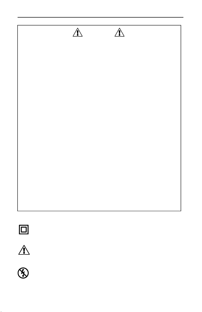
International Electrical Symbols
This symbol signifies that the current probe is protected by double
or reinforced insulation. Use only factory specified replacement
parts when servicing the instrument.
This symbol signifies CAUTION! and requests that the user refer to
the user manual before using the instrument.
This symbol refers to a type B current sensor. Do not apply around
or remove from HAZARDOUS LIVE conductors without additional
protective means (de-energizing the circuit or wearing protective
clothing suitable for high voltage work).
- 2 -
Page 5

AmpFlex® - Flexible AC Current Probes
Definition of Measurement Categories
CAT II: For measurements performed on circuits directly connected to
the electrical distribution system. Examples are measurements
on household appliances or portable tools.
CAT III: For measurements performed in the building installation at the
distribution level such as on hardwired equipment in fixed
installation and circuit breakers.
CAT IV: For measurements performed at the primary electrical supply
(<1000V) such as on primary overcurrent protection devices,
ripple control units, or meters
Receiving Your Shipment
Upon receiving your shipment, make sure that the contents are
consistent with the packing list. Notify your distributor of any missing
items. If the equipment appears to be damaged, file a claim immediately
with the carrier and notify your distributor at once, giving a detailed
description of any damage.
Packaging
Your AmpFlex® consists of the following items:
Flexible probe with electronic module
User manual
9V battery
- 3 -
Page 6

AmpFlex® - Flexible AC Current Probes
Description
The AmpFlex® is a flexible AC current transformer composed of a flexible
sensor and an electronic module. The flexible sensor permits
measurements on conductors where standard clamp-on probes could
not be used. In particular, it can be installed in tight spaces, around
breaker panels, around cable bundles, around wide or large bus bars, or
even wrapped around irregular shapes. The Shape Memory feature
enables the user to “pre-shape” the sensor before inserting it between or
around conductors. This feature facilitates closing, enhances user safety,
and alleviates the drooping effect typically associated with flexible
sensors.
The AmpFlex® is lightweight and does not use magnetic cores like
standard transformers. The transformation principle is based on an air
core. It presents virtually no load to the system under test, has a low
phase shift and excellent frequency response, and cannot be damaged
by overloads.
The sensor assembly is waterproof and insulated for 600V CAT IV;
1000V CAT III. The AmpFlex® meets EN 61010-1, is CE marked, and is
designed with materials and components to meet international agency
approvals.
The AmpFlex® has an mV output proportional to the current measured
for direct readings on DMMs, data loggers, oscilloscopes, and power or
harmonic meters. TRMS measurements are taken when connected to a
TRMS meter. The AmpFlex® is insensitive to DC currents and only the
AC component of the measured signal is measured.
The length of the flexible sensor can be selected in lengths of 24", 36",
and 48" in length. Consult the factory for custom lengths, ranges and/or
features.
- 4 -
Page 7
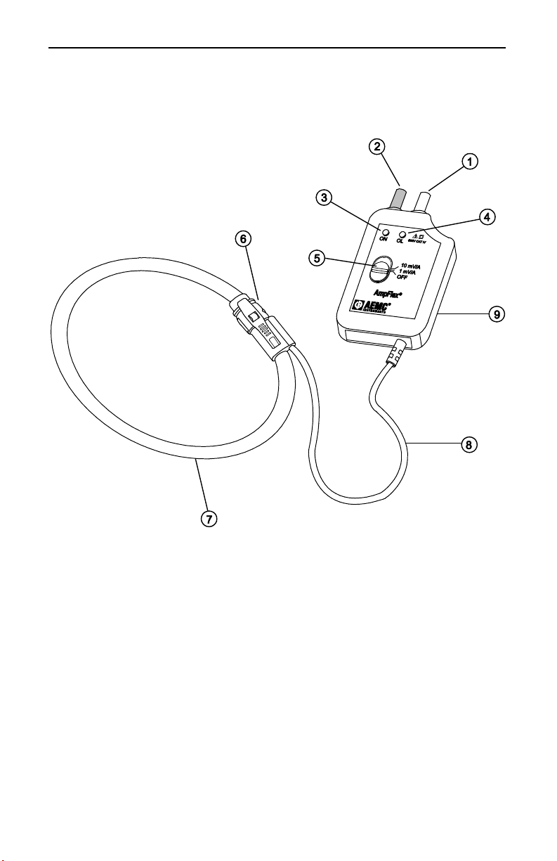
AmpFlex®
AmpFlex® - Flexible AC Current Probes
1. Positive: Red Banana Plug (+)
2. Common: Black Banana Plug (-)
3. Power ON Indicator (Green LED)
4. Overload Indicator (Red LED)
5. Range Selection Switch
6. AmpFlex® Connector/Latch
Figure 1
7. Flexible Sensor
(Diameter 0.5", 12.5mm)
8. Lead from Sensor to Module
(6.5 ft, 2m)
9. Electronic Module -
Descriptive Label on Back
Case (range, model, etc.)
- 5 -
Page 8

AmpFlex® - Flexible AC Current Probes
Features
Models to measure from 0.5Arms to 30,000Arms
Accuracy 1% of Reading
TRMS measurements when connected to a TRMS instrument
No core saturation or damage if overloaded
Overrange LED for measurement circuitry
600V CAT IV; 1000V CAT III; EN 61010; CE Mark
Waterproof sensor
9V battery for typical 150 hour continuous operation
Shape Memory for custom pre-shaping of sensor before use
(no drooping)
Very high frequency response
Low phase shift for power
Insensitive to DC, measures only AC component on DC + AC signals
Excellent linearity
Lightweight
Accessories
Banana (Female) / BNC (Male) Adapter ..................... Cat. # 2118.46
For connection of the AmpFlex® to SLII Models L101, L102, L562,
BNC terminals on scopes and other displaying instruments.
- 6 -
Page 9

AmpFlex® - Flexible AC Current Probes
Standard Models
Model
300-24-2-10 30/300A 100/10mV/A 24” (610mm) 8” (190mm) 2112.88
1000-24-1-1 1000A 1mV/A 24” (610mm) 8” (190mm) 2112.39
1000-24-2-1 100/1000A 10/1mV/A 24” (610mm) 8” (190mm) 2112.98
1000-36-2-1 100/1000A 10/1mV/A 36” (910mm) 11” (290mm) 2113.00
3000-24-2-0.3 300/3000A 3.3/0.3mV/A 24” (610mm) 8” (190mm) 2114.87*
3000-24-1-1 3000A 1mV/A 24” (610mm) 8” (190mm) 2112.46
3000-36-1-1 3000A 1mV/A 36” (910mm) 11” (290mm) 2112.48
3000-24-2-1 300/3000A 10/1mV/A 24” (610mm) 8” (190mm) 2113.05
3000-36-2-1 300/3000A 10/1mV/A 36” (910mm) 11” (290mm) 2112.00
3000-48-2-1 300/3000A 10/1mV/A 48” (1220mm) 15” (390mm) 2112.01
6000-36-2-0.1 600/6000A 1/0.1mV/A 36” (910mm) 11” (290mm) 2113.21
30000-24-2-0.1 3000/30,000A 1/0.1mV/A 24” (610mm) 8” (190mm) 2113.33
Measurement
Range
Output
Sensor
Length
*This model (Cat. #2114.87) is recommended to be used with our Simple Logger® II Models
L101, L102 & L562.
All of our AmpFlex® models are designed to be used with recorders or power analyzers with a
voltage AC input. A scale factor may need to be entered into the recorder to display the exact
value.
Custom lengths and ranges are available. Contact us: sales@aemc.com
Max
Conductor
Size
Cat. #
- 7 -
Page 10

AmpFlex® - Flexible AC Current Probes
Phase Shift @
Specifications
Model 300A 30/300A 1000A 100/1000A
Measurement
Range
Accuracy
Output Signal
Crest Factor
(mid-range)
50/60Hz
Residual Noise
Model # 3000A 300/3000A 3000/30000A 600/6000A
Measurement
Range
Accuracy
Output Signal
Crest Factor
(mid-range)
Phase Shift
@ 50/60Hz
Residual Noise
*Reference Conditions: 25°C ± 5°K, 20 to 75% RH, 1 minute warm-up, battery at 9V ± 0.5V, conductor
center, external DC magnetic field < 40A/m, no external AC magnetic field, no external electrical field, 10
to 100Hz, sine wave. See accuracy curves for low currents.
5 to 300A 5 to 300A 5 to 1000A 5 to 1000A
±1% +200mA ±1% +200mA ±1% +200mA ±1% +200mA
10mV/A
3.0 3.0 9.0 9.0
1.5° 1.3° 0.7° 0.7°
200mA 200mA 200mA 200mA
5 to 3000A 5 to 3000A 5-30000A 5 to 6000A
±1% +200mA ±1% +200mA ±1% +1A ±1% +500mA
1mV/A
3.0 3.0 3.0 > 10
0.7° 0.7° 0.5° 0.5°
200mA 200mA 1A 500mA
100mV/A or
10mV/A
10mV/A or
1mV/A
1mV/A
1mV/A or
0.1mV/A
10mV/A or
1mV/A
1mV/A or
0.1mV/A
- 8 -
Page 11

AmpFlex® - Flexible AC Current Probes
Common Specifications
ELECTRICAL
Accuracy: 1% of reading ± residual noise
Frequency Range: 10 - 20,000Hz with current derating
Signal Output: 4.5V max
Working Voltage: 600V CAT IV; 1000V CAT III
Frequency Influence:
See Accuracy vs. Frequency curves on pages 18 and 19
Frequency Limitation:
See current derating curves (note no limitation on 300A Range) page 19
Influence of adjacent conductor in contact with sensor and
with AC signal: 0.2% typical, 2% maximum
Influence of conductor position in sensor: 0.5% typical, 4% max
Influence of shape of sensor: Oblong shape: 0.2% typical, 1% max
Common Mode Rejection: 100dB typical, 80dB min
ENVIRONMENTAL SPECIFICATIONS
Operating Temperature Range: -14° to 131°F (-10° to +55°C)
Storage Temperature Range: -40° to 158°F (-40° to +70°C)
Influence of Temperature:
Sensor: -14° to 194°F (-10° to 90°C); 0.15% per 18°F (10°C) typical,
0.5% per 18°F 10°C max
Module: -14° to 131°F (-10° to 55°C); 0.15% per 18°F (10°C) typical,
0.5% per 18°F (10°C) max
Influence of Relative Humidity:
10 to 90% RH: 0.2% typical, 0.5% maximum
Operating Relative Humidity:
50° to 86°F (10° to 30°C); 85° ± 5% RH (without condensation)
104° to 122°F (40° to 50°C); 45° ± 5% RH (without condensation)
Altitude:
Operating: 0 to 2000m, working voltage derating above
Non-operating: 0 to 12,000m
- 9 -
Page 12

AmpFlex® - Flexible AC Current Probes
MECHANICAL SPECIFICATIONS
Module Output: Two 4 mm safety banana jacks
Standard 3/4" (19mm) spacing
Battery: 9V Alkaline (NEDA 1604A, IEC 6LR61) recommended
Battery Life: Useable from 9V to 7V, 150 hours typical (continuous use)
Low Battery: Power ON indicator (green LED) when battery voltage
7V, LED blinks when battery voltage is low
Overload Indication: Red LED ON indicates the selected range is
overloaded. Module output may not reflect the actual measurement
Dimensions (sensor):
24", 36", 48" & 60" nominal (± 1"), other lengths optional
Dimensions (Electronic Module): 4.9 x 2.5 x 1.1" (124 x 64 x 28mm)
Weight:
AmpFlex® 48" with battery: 0.95 lb
AmpFlex® 60" with battery: 1.13 lb
AmpFlex® 24" with battery: 0.74 lb
AmpFlex® 36" with battery: 0.89 lb
Connection Cable Length (sensor to module): 6.5 ft (2m)
Colors: Red sensor with dark gray connector and module, black
connection cable (sensor to module)
Drop Test: Per IEC 68-2-32
Vibration: Per IEC 68-2-6
Mechanical Shock: Per IEC 68-2-27
Weatherproofing: Module: IP40 (EN 60529)
SENSOR SPECIFICATIONS:
Weight: 10.8oz (302.4g)
Bend Radius: 0.75" (19mm) minimum
Bending Life: >10000 without performance deterioration
Waterproofing: IP 65
Resistance to Chemicals: Resistant to oils and aliphatic hydrocarbons
Diameter: 12mm ± 0.5mm
- 10 -
Page 13

AmpFlex® - Flexible AC Current Probes
Outer Sheath Material: Polyurethane, UL94V0
Dielectric Strength: 7500V
Latch Spring Life: >10,000 maneuvers
MATERIAL SPECIFICATIONS
Module:
UL 94V2, Color dark gray, Polycarbonate
Sensor Latch:
Material: Lexan 500R, UL94V0
Cable Assembly to Sensor:
UL 94V0, 1000V rating
SAFETY SPECIFICATIONS
Electrical:
Double insulation or reinforced insulation between primary or secondary
and outer case per EN 61010
600V CAT IV; 1000V CAT III
Pollution Degree 2
7.50kV, 50/60Hz, dielectric between secondary and the outer case
Electromagnetic Compatibility
Immunity: meets BF EN 61326-1 Industrial environment category
- Electrostatic discharge (meets EN 61000-4-2)
8kV in air – level 3 – class B
4kV on contact – level 2 – class B
- 10V/m radiated electromagnetic field (in line with EN 61000-4-3) –
class B
- Rapid transients (in line with EN 61000-4-4)
1kV – level 2 – class B
- Electric shocks (in line with EN 61000-4-5)
6kV – class B
- 11 -
Page 14

AmpFlex® - Flexible AC Current Probes
Instrument Compatibility
The AmpFlex® is compatible with any multimeter, AC voltmeter, or
other voltage measuring instrument with an input impedance greater
than 1M. To achieve the best overall accuracy, use the AmpFlex
with a AC voltmeter having an accuracy of 0.75% or better.
®
Operation
Please make sure that you have already read and fully understand the
WARNING section on page 2.
Making Measurements with the AmpFlex®:
Connect the electronic module to the AC Volt range of your DMM or
measuring instrument. Select the appropriate module output voltage
range. If the current magnitude is unknown, and if AmpFlex® has two
ranges, select the lowest mV/A output setting.
Wrap the flexible core around the conductor to be tested. If possible
within range, select the higher mV/A AmpFlex® output range to obtain
the best resolution. Do not exceed specified current range for the
output. Do not use on selected range if overload LED goes on.
Read the displayed value on the DMM and divide it by the range
selected (i.e. if reading = 2.59V with the 10mV/A output range, the
current flowing through the probe is 2590mV ÷ 10 = 259A).
For best accuracy, carefully center the conductor inside the flexible
core, and avoid if possible, the proximity of other conductors which
may create noise and interference (particularly near the latch).
True RMS measurements are obtained when the AmpFlex® is
connected to a True RMS meter. Note that the DC component is not
measured.
Tips for Making Precise Measurements:
When using the AmpFlex® with a meter, it is important to select the
range that provides the best resolution. Failure to do this may result in
measurement errors.
For best results, select the highest AmpFlex® output signal possible
and the most sensitive meter range for this output.
Make sure the DMM or measuring instrument can accurately measure
mVAC. Certain inexpensive DMM have poor resolution and accuracy
when measuring low mV AC.
For best accuracy, center the AmpFlex® around the conductor to be
measured. (See figure 2).
- 12 -
Page 15

AmpFlex® - Flexible AC Current Probes
Tips for Making Precise Measurements (continued):
To increase the sensitivity or measure on low currents, the AmpFlex®
may be wrapped several times around the conductor. Remember to
divide your reading by the number of turns for the actual
measurement (see Figure 4).
The overall measurement accuracy is the sum of the AmpFlex
accuracy and the displaying instrument accuracy.
®
Figure 2
- 13 -
Page 16

AmpFlex® - Flexible AC Current Probes
Tips for Making Precise Measurements (continued):
The AmpFlex® may be doubled around the conductor to be measured to
double the output. (See Figures 3 and 4 to show the different values on a
DMM while measuring 250AAC.)
Figure 3
- 14 -
Page 17

AmpFlex® - Flexible AC Current Probes
Tips for Making Precise Measurements (continued):
Figure 4
- 15 -
Page 18

AmpFlex® - Flexible AC Current Probes
Typical Response Curves:
- 16 -
Page 19

AmpFlex® - Flexible AC Current Probes
Typical Response Curves (cont.):
- 17 -
Page 20

AmpFlex® - Flexible AC Current Probes
Maintenance
Warning
For maintenance use only specified replacement parts.
To avoid electrical shock, do not attempt to perform any servicing
unless you are qualified to do so.
Do not perform any service while the AmpFlex® is on any circuit.
To avoid electrical shock and/or damage to the instrument, do not get
water or other foreign agents into the electronic module.
Also see warning on page 2.
Battery Replacement
If the power ON indicator (green LED) blinks or does not light up,
replace the battery.
Remove the AmpFlex® from any circuit before replacing the battery.
To replace the battery, open rear case, replace battery and
reassemble. The green LED should go on when the module is turned
on.
Cleaning
It is important to keep the probe sensor latch mating surfaces clean
and prevent foreign bodies from hampering the closing. The sensor
may be gently cleaned with a soft cloth, soap and water. Dry
immediately after cleaning. Avoid water penetration into the electronic
module.
Make sure the sensor, electronic module, and all leads are dry before
any further use.
- 18 -
Page 21

AmpFlex® - Flexible AC Current Probes
Repair and Calibration
To ensure that your instrument meets factory specifications, we recommend
that it be submitted to our factory Service Center at one-year intervals for
recalibration, or as required by other standards or internal procedures.
For instrument repair and calibration:
You must contact our Service Center for a Customer Service Authorization
number (CSA#). This will ensure that when your instrument arrives, it will be
tracked and processed promptly. Please write the CSA# on the outside of
the shipping container. If the instrument is returned for calibration, we need
to know if you want a standard calibration, or a calibration traceable to
N.I.S.T. (includes calibration certificate plus recorded calibration data).
Ship to: Chauvin Arnoux®, Inc.
d.b.a. AEMC® Instruments
15 Faraday Drive
Dover, NH 03820 USA
Tel: (800) 945-2362 (Ext. 360)
(603) 749-6434 (Ext. 360)
Fax: (603) 742-2346 or (603) 749-6309
repair@aemc.com
(Or contact your authorized distributor)
Costs for repair, standard calibration, and calibration traceable to N.I.S.T. are
available.
NOTE: You must obtain a CSA# before returning any instrument.
Technical and Sales Assistance
If you are experiencing any technical problems, or require any assistance
with the proper operation or application of your instrument, please call, mail,
fax or e-mail our technical support hotline:
Chauvin Arnoux®, Inc.
d.b.a. AEMC® Instruments
200 Foxborough Boulevard
Foxborough, MA 02035, USA
Phone: (800) 343-1391
(508) 698-2115
Fax: (508) 698-2118
techsupport@aemc.com
www.aemc.com
NOTE: Do not ship Instruments to our Foxborough, MA address.
Page 22

Limited Warranty
The AmpFlex® Probe is warranted to the owner for a period of 1 year from
the date of original purchase against defects in manufacture. This limited
warranty is given by AEMC® Instruments, not by the distributor from whom it
was purchased. This warranty is void if the unit has been tampered with,
abused or if the defect is related to service not performed by AEMC®
Instruments.
Full warranty coverage and product registration is available on our
website at: www.aemc.com/warranty.html.
Please print the online Warranty Coverage Information for your
records.
What AEMC® Instruments will do:
If a malfunction occurs within the one-year period, you may return the
instrument to us for repair, provided we have your warranty registration
information on file or a proof of purchase. AEMC® Instruments will, at its
option, repair or replace the faulty material.
REGISTER ONLINE AT:
www.aemc.com
Warranty Repairs
What you must do to return an Instrument for Warranty Repair:
First, request a Customer Service Authorization Number (CSA#) by phone or
by fax from our Service Department (see address below), then return the
instrument along with the signed CSA Form. Please write the CSA# on the
outside of the shipping container. Return the instrument, postage or
shipment pre-paid to:
Chauvin Arnoux®, Inc. d.b.a. AEMC® Instruments
15 Faraday Drive • Dover, NH 03820 USA
Tel: (800) 945-2362 (Ext. 360)
(603) 749-6434 (Ext. 360)
Fax: (603) 742-2346 or (603) 749-6309
repair@aemc.com
Caution: To protect yourself against in-transit loss, we recommend you
insure your returned material.
NOTE: You must obtain a CSA# before returning any instrument.
Page 23

AmpFlex® - Flexible AC Current Probes
Chauvin Arnoux®, Inc. d.b.a AEMC® Instruments
15 Faraday Drive • Dover, NH 03820, USA
www.aemc.com
99-MAN 100122 v20 6/16
 Loading...