

Page 1
Instruction
STOP!
THIS PRODUCT HAS LEGAL RESTRICTIONS.
READ THIS BEFORE INSTALLING/USING!
THIS PRODUCT MAY BE USED SOLELY ON VEHICLES USED IN SANCTIONED COMPETITION WHICH MAY
NEVER BE USED UPON A PUBLIC ROAD OR HIGHWAY, UNLESS PERMITTED BY SPECIFIC REGULATORY
EXEMPTION. (VISIT THE “EMISSIONS” PAGE AT HTTP://WWW.SEMASAN.COM/EMISSIONS FOR STATE BY
STATE DETAILS.)
IT IS THE RESPONSIBILITY OF THE INSTALLER AND/OR USER OF THIS PRODUCT TO ENSURE THAT IT IS
USED IN COMPLIANCE WITH ALL APPLICABLE LAWS AND REGULATIONS. IF YOU HAVE PURCHASED
THIS PRODUCT IN ERROR, DO NOT INSTALL AND/OR USE IT. PLEASE CONTACT THE RETAILER FROM
WHOM YOU PURCHASED THE PRODUCT TO ARRANGE A RETURN FOR A FULL REFUND OR VISIT
AEMELECTRONICS.COM/PRODUCT-LEGAL-RESTRICTIONS FOR FURTHER INSTRUCTIONS.
Manual
Infinity Supported Application
GM LSX 24X/58X
WARNING: This installation is not for the tuning novice! Use this system with EXTREME caution! The AEM
Infinity Programmable EMS allows for total flexibility in engine tuning. Misuse or improper tuning of this
product can destroy your engine! If you are not well versed in engine dynamics and the tuning of engine
management systems DO NOT attempt the installation. Refer the installation to an AEM-trained tuning
shop or call 800-423-0046 for technical assistance.
NOTE: All supplied AEM calibrations, Wizards and other tuning information are offered as potential
starting points only. IT IS THE RESPONSIBILITY OF THE ENGINE TUNER TO ULTIMATELY CONFIRM IF THE
CALIBRATION IS SAFE FOR ITS INTENDED USE. AEM holds no responsibility for any engine damage that
results from the misuse or mistuning of this product!
AEM Performance Electronics, 2205 126th Street Unit A, Hawthorne, CA 90250
AEM Performance Electronics
Phone: (310) 484-2322 Fax: (310) 484-0152
http://www.aemelectronics.com
Instruction Part Number:
Document Build 8/26/2014
Page 2

2
OVERVIEW
The AEM Infinity EMS can be adapted to most fuel injected engines. The base configuration files
available for the Infinity ECU are starting points only and will need to be modified for your specific
application. This manual lists the files available and suggested changes for your engine. It also includes
a pinout with suggestions for adapting the Infinity ECU to your engine harness. It is the responsibility of
the installer to verify this information before starting the engine.
MODELS
GM
LSX 24X/58X
DOWNLOADABLE FILES
Files can be downloaded from www.aeminfinity.com. An experienced tuner must be available to configure
and manipulate the data before driving can commence. The Quick Start Guide and Full Manual describe
the steps for logging in and registering at www.aeminfinity.com. These documents are available for
download in the Support section of the AEM Electronics website: http://www.aemelectronics.com/
products/support/instructions.
FILES
Downloadable files for GM LSX 24X/58X
7100-XXXX-62 Infinity-10 (XXXX = serial number)
7101-XXXX-63 Infinity-8 (XXXX = serial number)
To properly control your engine, the application specific settings listed in this document MUST be
confirmed or changed to the given settings. Failure to do so may result in improper function and possible
ECU damage.
ADAPTER HARNESS OPTIONS
30-3702 Harness, Mini Lead
This harness includes a fused power distribution center with main relay. Pre-terminated connectors are
available for the internal UEGO sensors and AEMNet. A bag of multi-color flying leads is included to
simplify custom harness builds.
30-3701 Connector Kit
This kit includes mating connectors and terminals for the Infinity. It also includes a main relay kit which
is necessary for proper power distribution. This kit is best suited for experienced installers who want to
build their own harness.
30-3600 O2 Sensor Extension Harness
30-3601 IP67 Comms Cable
30-3602 IP67 Logging Cable
© 2014 AEM Performance Electronics
Page 3
Infinity Supported Application
IMPORTANT APPLICATION SPECIFIC SETTINGS
Infinity Tuner Wizard Setup
Engine
In the Wizard Basic tab confirm the following settings:
Number of Cylinders = 8
Engine Cycle Type = 4 Stroke
Ignition Type = Sequential (Coil On Plug)
Firing Order = 1-8-7-2-6-5-4-3 Chevy LS1
Cam/Crank
In the Wizard Cam/Crank tab confirm the following setting:
58X – GM LS Engine 58X
OR
24X – GM LS Engine 24X
3
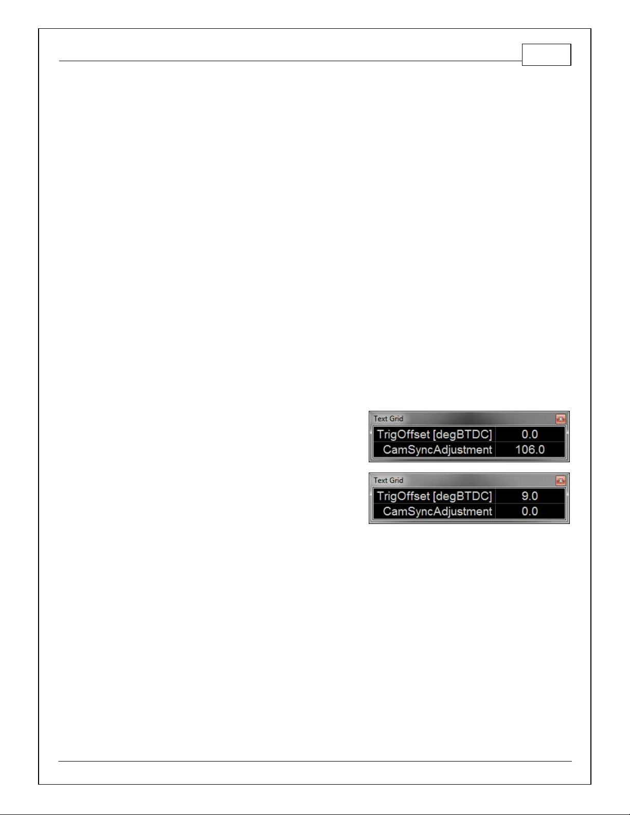
Add a text grid control to your layout and select the following channels. Make sure their values match
the settings below for initial timing sync. These values will be populated when the Cam/Crank pattern is
selected.
58X:
TrigOffset [degBTDC] = 0.0
CamSyncAdjustment = 106.0
SpkDelayComp [us/10] = 1000
24X:
TrigOffset [degBTDC] = 9.0
CamSyncAdjustment = 0.0
SpkDelayComp [us/10] = 1500
Ignition Sync
See QuickStart Guide section Setup: Ignition Sync for instructions on timing sync.
Manifold Pressure
Go to Setup Wizard Basic Sensors page. Select MAP Sensor Setup and choose the GM LS2 9359409
(1 Bar) from the list of sensors.
Idle Setup
Go to Setup Wizard Idle page and use the following settings (stepper idle only):
Idle Stepper Max Steps = 96
Idle Airflow Invert = checked
© 2014 AEM Performance Electronics
Page 4

4
Oil Pressure
Go to Setup Wizard Basic Sensors page. Choose Oil Pressure Sensor Setup and select the GM LS2 Oil
Pressure Sensor.
© 2014 AEM Performance Electronics
Page 5
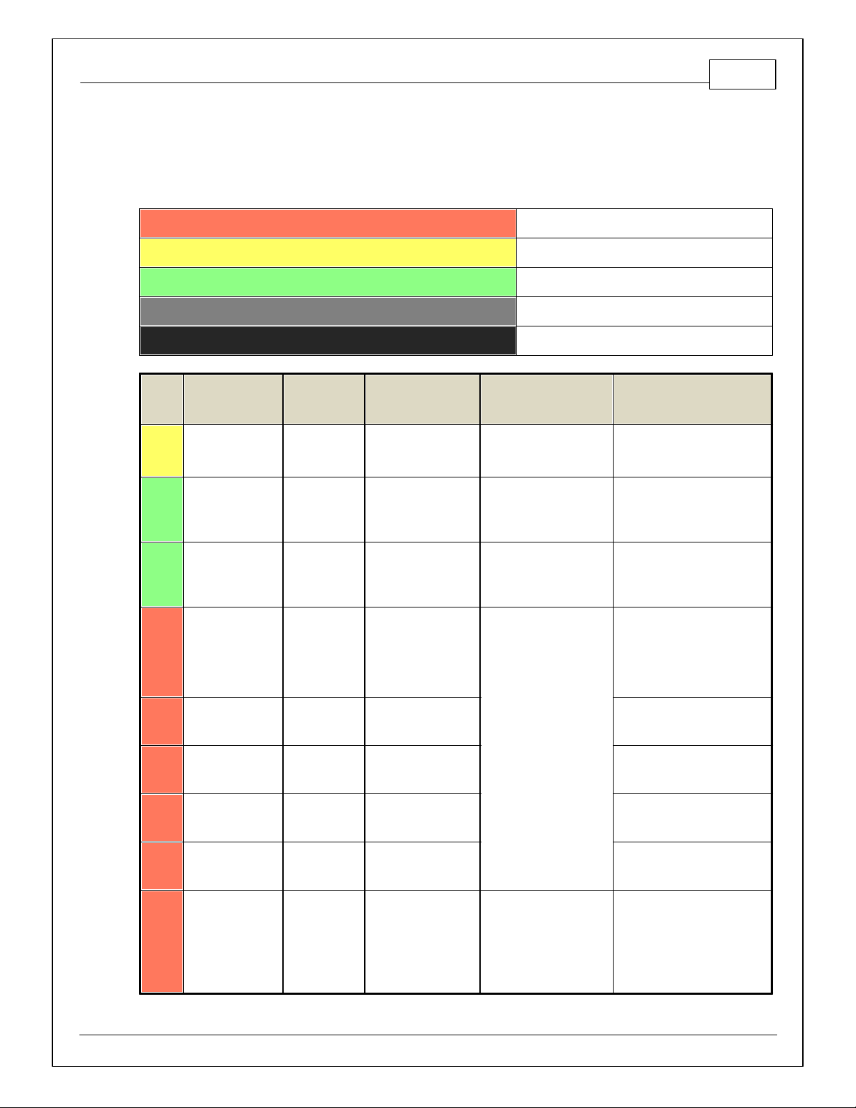
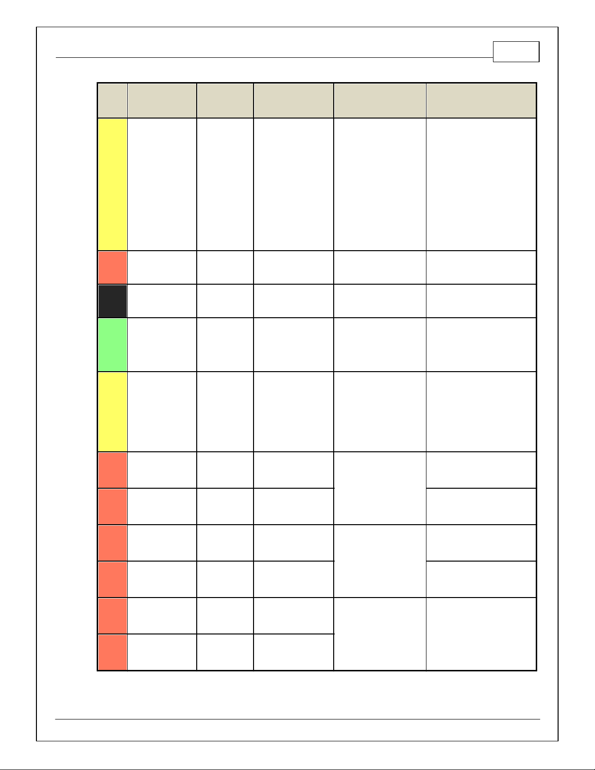
PINOUTS
Dedicated
Dedicated and not reconfigurable
Assigned
Assigned but reconfigurable
Available
Available for user setup
Not Applicable
Not used in this configuration
Required
Required for proper function
Infinity
Pin
Hardware
Reference
7100-XXXX-62
7101-XXXX-63
Function
Dest. Pin GM LS
Hardware Specification
Notes
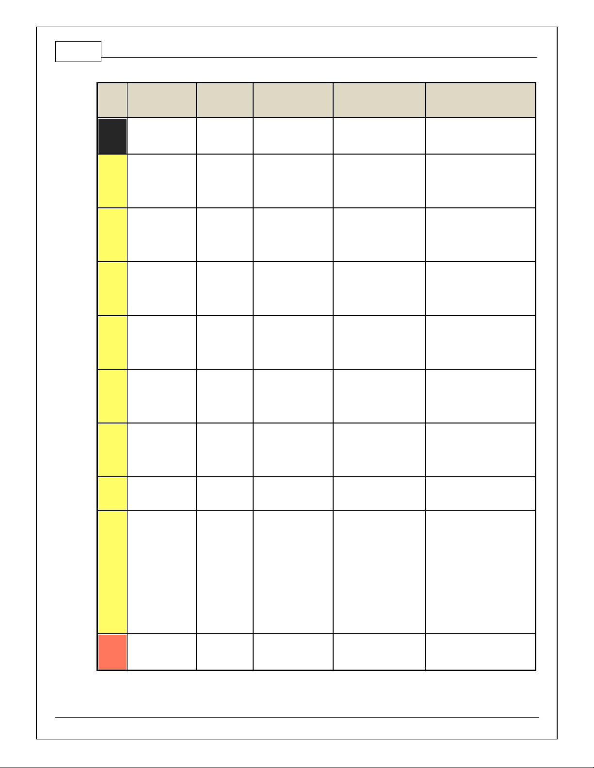
C1-1
LowsideSwitch_4
A/C Relay
Control
A/C Clutch Relay Ctrl
Lowside switch, 4A max,
NO internal fly back diode.
See Setup Wizard "LowSide
Assignment Tables" for output
assignment
C1-2
LowsideSwitch_5
LS5
Lowside switch, 4A max
with internal f lyback diode.
Inductiv e load should NOT
have full time power.
See Setup Wizard Page "LowSide
Assignment Tables" for output
assignment and 2D table
"LS5_Duty [%]" for activ ation.
C1-3
LowsideSwitch_6
LS6
Lowside switch, 4A max
with internal f lyback diode.
Inductiv e load should NOT
have full time power.
See Setup Wizard Page "LowSide
Assignment Tables" for output
assignment and 2D table
"LS6_Duty [%]" for activ ation.
C1-4
UEGO 1 Heat
UEGO 1 Heat
Bosch UEGO controller
Lowside switch for UEGO heater
control. Connect to pin 4 of
Bosch UEGO sensor. NOTE that
pin 3 of the Sensor is heater (+)
and must be power by a fused/
switched 12V supply .
C1-5
UEGO 1 IA
UEGO 1 IA
Trim Current signal. Connect to
pin 2 of Bosch UEGO sensor.
C1-6
UEGO 1 IP
UEGO 1 IP
Pumping Current signal. Connect
to pin 6 of Bosch UEGO sensor.
C1-7
UEGO 1 UN
UEGO 1 UN
Nernst Voltage signal. Connect to
pin 1 of Bosch UEGO sensor.
C1-8
UEGO 1 VM
UEGO 1 VM
Virtual Ground signal. Connect to
pin 5 of Bosch UEGO sensor.
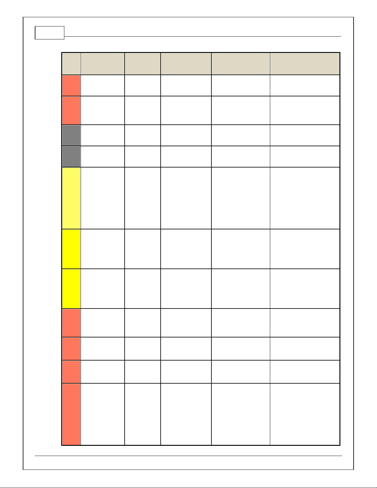
C1-9
Flash_Enable
Flash Enable
10K pulldown
Not usually needed f or automatic
firmware updates through Inf inity
Tuner. If connection errors occur
during update, connect 12 v olts
to this pin before proceeding with
upgrade. Disconnect the 12 v olts
signal after the update.
Infinity Pinouts
Infinity Supported Application
5
© 2014 AEM Performance Electronics
Page 6
6
Infinity
Pin
Hardware
Reference
7100-XXXX-62
7101-XXXX-63
Function
Dest. Pin GM LS
Hardware Specification
Notes
C1-10
+12V_R8C_CPU
Battery Perm
Power
Battery Positive
Voltage
Dedicated power
management CPU
Full time battery power. MUST be
powered before the ignition switch
input is triggered. (See C1-65.)
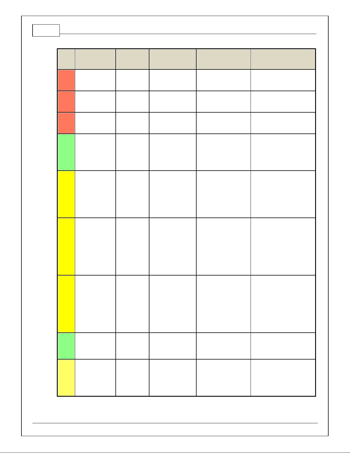
C1-11
Coil 4
Coil 4
IC 4 Control
25 mA max source current
0–5V Falling edge fire. DO NOT
connect directly to coil primary .
Must use an ignitor OR CDI that
accepts a FALLING edge fire
signal.
C1-12
Coil 3
Coil 3
IC 3 Control
25 mA max source current
0–5V Falling edge fire. DO NOT
connect directly to coil primary .
Must use an ignitor OR CDI that
accepts a FALLING edge fire
signal.
C1-13
Coil 2
Coil 2
IC 2 Control
25 mA max source current
0–5V Falling edge fire. DO NOT
connect directly to coil primary .
Must use an ignitor OR CDI that
accepts a FALLING edge fire
signal.
C1-14
Coil 1
Coil 1
IC 1 Control
25 mA max source current
0–5V Falling edge fire. DO NOT
connect directly to coil primary .
Must use an ignitor OR CDI that
accepts a FALLING edge fire
signal.
C1-15
Coil 6
Coil 6
IC 6 Control
25 mA max source current
0–5V Falling edge fire. DO NOT
connect directly to coil primary .
Must use an ignitor OR CDI that
accepts a FALLING edge fire
signal.
C1-16
Coil 5
Coil 5
IC 5 Control
25 mA max source current
0–5V Falling edge fire. DO NOT
connect directly to coil primary .
Must use an ignitor OR CDI that
accepts a FALLING edge fire
signal.
C1-17
LowsideSwitch_2
Coolant Fan 1
Control
Cooling Fan Control
Lowside switch, 4A max,
NO internal fly back diode.
See "LowSide Assignment Tables"
for output assignment.
C1-18
LowsideSwitch_3
MIL Output
Lowside switch, 4A max
with internal f lyback diode.
Inductiv e load should NOT
have full time power.
See Wizard page "LowSide
Assignment Tables" for output
assignment.
MIL Activ ates when any of the
following f lags are true:
ErrorAirTemp, ErrorBaro,
ErrorCoolantTemp, ErrorEBP,
ErrorFuelPressure,
UEGO_0_Diag_error,
UEGO_1_Diag_error,
ErrorMAFAnalog, ErrorMAFDigital,
ErrorMAP, ErrorOilPressure,
ErrorThrottle.
C1-19
AGND_1
Sensor Ground
TP Sensor 1 Ground/
Engine Oil Pressure
Sensor Ground
Dedicated analog ground
Analog 0–5V sensor ground
© 2014 AEM Performance Electronics
Page 7

Infinity Supported Application
Infinity
Pin
Hardware
Reference
7100-XXXX-62
7101-XXXX-63
Function
Dest. Pin GM LS
Hardware Specification
Notes
C1-20
AGND_1
Sensor Ground
Mass Airflow (incl IAT
sensor) Sensor Ground/
Engine Coolant Temp
Sensor Ground
Dedicated analog ground
Analog 0–5V sensor ground
C1-21
Crankshaf t Position
Sensor Hall
Crankshaf t
Position Sensor
Hall
CKP Sensor Signal
10K pullup to 12V. Will work
with ground or f loating
switches.
See Setup Wizard page Cam/
Crank f or options.
C1-22
Camshaf t Position
Sensor 1 Hall
Camshaf t
Position Sensor
1 Hall
CMP Sensor Signal
10K pullup to 12V. Will work
with ground or f loating
switches.
See Setup Wizard page Cam/
Crank f or options.
C1-23
Digital_In_2
Camshaf t
Position Sensor
2 Hall
Mass Air Flow Sensor
(Digital) Signal
10K pullup to 12V. Will work
with ground or f loating
switches.
See Setup Wizard page Cam/
Crank f or options.
C1-24
Digital_In_3
Turbo Speed Hz
10K pullup to 12V. Will work
with ground or f loating
switches.
See Setup Wizard page Input
Function Assignment f or
calibration constant. TurboSpeed
[RPM] = Turbo [Hz] * Turbo Speed
Calibration.
C1-25
Digital_In_4
Vehicle Speed
Sensor
10K pullup to 12V. Will work
with ground or f loating
switches.
See Setup Wizard page Input
Function Assignment f or
calibration constant.
C1-26
Digital_In_5
Flex Fuel
10K pullup to 12V. Will work
with ground or f loating
switches.
See channel FlexDigitalIn [Hz] f or
raw frequency input data.
C1-27
Knock Sensor 1
Knock Sensor 1
Knock Sensor 1 Signal
Dedicated knock signal
processor
See Setup Wizard page Knock
Setup for options.
C1-28
Knock Sensor 2
Knock Sensor 2
Knock Sensor 2 Signal
Dedicated knock signal
processor
See Setup Wizard page Knock
Setup for options.
C1-29
+12V_Relay_Control
+12V Relay
Control
See Main Relay/Fuel
Pump Schematic
0.7A max ground sink f or
external relay control
Will activate at key on and at
key off according to the
conf iguration settings.
C1-30
Power Ground
Ground
Power Ground
Connect directly to battery
ground.
C1-31
CANL_Aout
AEMNet CANL
Dedicated High Speed CAN
Transceiv er
Recommend twisted pair (one
twist per 2") with terminating
resistor. Contact AEM f or
additional information.
C1-32
CANH_Aout
AEMNet CANH
Dedicated High Speed CAN
Transceiv er
Recommend twisted pair (one
twist per 2") with terminating
resistor. Contact AEM f or
additional information.
C1-33
LowsideSwitch_1
Boost Control
Lowside switch, 4A max
with internal f lyback diode.
Inductiv e load should NOT
have full time power.
See Setup Wizard page Boost
Control f or options. Monitor
BoostControl [%] channel f or
output state.
7
© 2014 AEM Performance Electronics
Page 8

8
Infinity
Pin
Hardware
Reference
7100-XXXX-62
7101-XXXX-63
Function
Dest. Pin GM LS
Hardware Specification
Notes
C1-34
Lowside Fuel Pump
drive
Fuel Pump
See Main Relay/Fuel
Pump Schematic
Lowside switch, 4A max,
NO internal fly back diode.
Switched ground. Will prime for 2
seconds at key on and activ ate if
RPM > 0.
C1-35
Analog_In_7
Throttle Position
Sensor
TP Sensor 1 Signal
12 bit A/D, 100K pullup to
5V
0–5V analog signal. Use +5V Out
pins as power supply and Sensor
Ground pins as the low ref erence.
Do not connect signals
referenced to +12V as this can
permanently damage the ECU.
See the Setup Wizard Set Throttle
Range page f or automatic min/
max calibration. Monitor the
Throttle [%] channel. Also
DB1_TPSA [%] for DBW
applications.
C1-36
Analog_In_8
MAP Sensor
Map Sensor Signal
12 bit A/D, 100K pullup to
5V
0–5V analog signal. Use +5V Out
pins as power supply and Sensor
Ground pins as the low ref erence.
Do not connect signals
referenced to +12V as this can
permanently damage the ECU.
See the Setup Wizard Set
Manifold Pressure page f or setup
and calibration. Monitor the MAP
[kPa] channel.
C1-37
Analog_In_9
Fuel Pressure
Fuel Pressure Signal
12 bit A/D, 100K pullup to
5V
0–5V analog signal. Use +5V Out
pins as power supply and Sensor
Ground pins as the low ref erence.
Do not connect signals
referenced to +12V as this can
permanently damage the ECU.
See the Setup Wizard Fuel
Pressure page for setup and
calibration. Monitor the
FuelPressure [psig] channel.
C1-38
Analog_In_10
Baro Sensor
12 bit A/D, 100K pullup to
5V
0–5V analog signal. Use +5V Out
pins as power supply and Sensor
Ground pins as the low ref erence.
Do not connect signals
referenced to +12V as this can
permanently damage the ECU.
See the Setup Wizard Barometric
Pressure page for setup and
calibration. Monitor the BaroPress
[kPa] channel.
C1-39
Analog_In_11
Shift Switch
Input
12 bit A/D, 100K pullup to
5V
0–5V analog signal. Use +5V Out
pins as power supply and Sensor
Ground pins as the low ref erence.
Do not connect signals
referenced to +12V as this can
permanently damage the ECU.
See the 1D lookup table
'ShiftSwitch' f or setup. Also
assignable to multiple functions.
See Setup Wizard for details.
© 2014 AEM Performance Electronics
Page 9
Infinity Supported Application
Infinity
Pin
Hardware
Reference
7100-XXXX-62
7101-XXXX-63
Function
Dest. Pin GM LS
Hardware Specification
Notes
C1-40
Analog_In_12
Mode Switch
12 bit A/D, 100K pullup to
5V
0–5V analog signal. Use +5V Out
pins as power supply and Sensor
Ground pins as the low ref erence.
Do not connect signals
referenced to +12V as this can
permanently damage the ECU.
See the 1D lookup table
'ModeSwitch' for input state.
A multi-position rotary switch
such as AEM P/N 30-2056 is
recommended.
Also assignable to multiple
functions. See Setup Wizard f or
details.
C1-41
+5V_Out_1
+5V Out
Fuel Sender +5V
Regulated, fused +5V
supply for sensor power
Analog sensor power
C1-42
+5V_Out_1
+5V Out
Engine Oil Pressure
Sensor +5V
Regulated, fused +5V
supply for sensor power
Analog sensor power
C1-43
HighsideSwitch_1
HS1 (switched
12V)
0.7A max, High Side Solid
State Relay
See Setup Wizard page 'HighSide
Assigment Tables' f or
conf iguration options.
See 2D lookup table 'HS1_Table'
for activation settings.
C1-44
HighsideSwitch_0
VTEC
0.7A max, High Side Solid
State Relay
See Setup Wizard page 'HighSide
Assigment Tables' f or
conf iguration options.
See 2D lookup table 'HS0_Table'
for activation settings.
See Setup Wizard page 'VTEC'
for default activation criteria.
C1-45
Crankshaf t Position
Sensor VR+
Crankshaf t
Position Sensor
VR+
Dif ferential Variable
Reluctance Zero Cross
Detection
See Setup Wizard page Cam/
Crank f or options.
C1-46
Crankshaf t Position
Sensor VR-
Crankshaf t
Position Sensor
VR-
See Setup Wizard page Cam/
Crank f or options.
C1-47
Camshaf t Position
Sensor 1 VR-
Camshaf t
Position Sensor
1 VR-
Dif ferential Variable
Reluctance Zero Cross
Detection
See Setup Wizard page Cam/
Crank f or options.
C1-48
Camshaf t Position
Sensor 1 VR+
Camshaf t
Position Sensor
1 VR+
See Setup Wizard page Cam/
Crank f or options.
C1-49
VR+_In_2
Non Driv en Lef t
Wheel Speed
Sensor +
Dif ferential Variable
Reluctance Zero Cross
Detection
See Non Driven Wheel Speed
Calibration in the Setup Wizard
Input Function Assignment page.
C1-50
VR-_In_2
Non Driv en Lef t
Wheel Speed
Sensor -
9
© 2014 AEM Performance Electronics
Page 10

10
Infinity
Pin
Hardware
Reference
7100-XXXX-62
7101-XXXX-63
Function
Dest. Pin GM LS
Hardware Specification
Notes
C1-51
VR-_In_3
Driv en Left
Wheel Speed
Sensor -
Dif ferential Variable
Reluctance Zero Cross
Detection
See Driven Wheel Speed
Calibration in the Setup Wizard
Input Function Assignment page.
C1-52
VR+_In_3
Driv en Left
Wheel Speed
Sensor +
C1-53
DBW1 Motor -
DBW Motor
Control Close
5.0A max Throttle Control
Hbridge Driv e
+12V to close
C1-54
DBW1 Motor +
DBW Motor
Control Open
5.0A max Throttle Control
Hbridge Driv e
+12V to open
C1-55
Power Ground
Ground
Power Ground
Connect directly to battery
ground.
C1-56
Injector 6
Injector 6
Fuel Injector 6 Control
Saturated or peak and hold,
3A max continuous
Injector 6
C1-57
Injector 5
Injector 5
Fuel Injector 5 Control
Saturated or peak and hold,
3A max continuous
Injector 5
C1-58
Injector 4
Injector 4
Fuel Injector 4 Control
Saturated or peak and hold,
3A max continuous
Injector 4
C1-59
Injector 3
Injector 3
Fuel Injector 3 Control
Saturated or peak and hold,
3A max continuous
Injector 3
C1-60
Power Ground
Ground
Power Ground
Connect directly to battery
ground.
C1-61
+12V
+12V In
Powertrain Relay +12V
12 v olt power f rom relay
12 v olt power f rom relay. Relay
must be controlled by +12V
Relay Control signal, pin C1-29
above.
C1-62
Injector 2
Injector 2
Fuel Injector 2 Control
Saturated or peak and hold,
3A max continuous
Injector 2
C1-63
Injector 1
Injector 1
Fuel Injector 1 Control
Saturated or peak and hold,
3A max continuous
Injector 1
C1-64
+12V
+12V In
Powertrain Relay +12V
12 v olt power f rom relay
12 v olt power f rom relay. Relay
must be controlled by +12V
Relay Control signal pin C1-29
above.
C1-65
+12V_SW
Ignition Switch
10K pulldown
Full time battery power must be
available at C1-10 before this
input is triggered.
C1-66
Analog_In_Temp_1
Coolant Temp
Sensor
Engine Coolant
Temperature Signal
12 bit A/D, 2.49K pullup to
5V
See "Coolant Temperature" Setup
Wizard f or selection.
© 2014 AEM Performance Electronics
Page 11

Infinity Supported Application
Infinity
Pin
Hardware
Reference
7100-XXXX-62
7101-XXXX-63
Function
Dest. Pin GM LS
Hardware Specification
Notes
C1-67
Analog_In_Temp_2
Intake Air
Temperature
IAT Sensor Signal
12 bit A/D, 2.49K pullup to
5V
See "Air Temperature" Setup
Wizard f or selection.
C1-68
Harness_Analog_In_
Temp_3
Oil Temperature
Sensor
12 bit A/D, 2.49K pullup to
5V
See 1D table OilTempCal table
for calibration data and OilTemp
[C] for channel data.
C1-69
Stepper_2A
Stepper 2A
IAC Coil B High
Automotiv e, Programmable
Stepper Driv er, up to 28V
and ±1.4A
Be sure that each internal coil of
the stepper motor is properly
paired with the 1A/1B and 2A/2B
ECU outputs. Supports Bi-Polar
stepper motors only .
C1-70
Stepper_1A
Stepper 1A
IAC Coil A High
Automotiv e, Programmable
Stepper Driv er, up to 28V
and ±1.4A
Be sure that each internal coil of
the stepper motor is properly
paired with the 1A/1B and 2A/2B
ECU outputs. Supports Bi-Polar
stepper motors only .
C1-71
Stepper_2B
Stepper 2B
IAC Coil B Low
Automotiv e, Programmable
Stepper Driv er, up to 28V
and ±1.4A
Be sure that each internal coil of
the stepper motor is properly
paired with the 1A/1B and 2A/2B
ECU outputs. Supports Bi-Polar
stepper motors only .
C1-72
Stepper_1B
Stepper 1B
IAC Coil A Low
Automotiv e, Programmable
Stepper Driv er, up to 28V
and ±1.4A
Be sure that each internal coil of
the stepper motor is properly
paired with the 1A/1B and 2A/2B
ECU outputs. Supports Bi-Polar
stepper motors only .
C1-73
Power Ground
Ground
Power Ground
Connect directly to battery
ground.
C2-1
DBW2 Motor +
DBW Motor
Control Open
5.0A max Throttle Control
Hbridge Driv e
+12V to open
C2-2
DBW2 Motor -
DBW Motor
Control Close
5.0A max Throttle Control
Hbridge Driv e
+12V to close
C2-3
Power Ground
Ground
Power Ground
Connect directly to battery
ground.
C2-4
Injector 7
Injector 7
Fuel Injector 7 Control
Saturated or peak and hold,
3A max continuous
Injector 7
C2-5
Injector 8
Injector 8
Fuel Injector 8 Control
Saturated or peak and hold,
3A max continuous
Injector 8
C2-6
Injector 9
Injector 9
Saturated or peak and hold,
3A max continuous
Injector 9
C2-7
Injector 10
Injector 10
Saturated or peak and hold,
3A max continuous
Injector 10
11
© 2014 AEM Performance Electronics
Page 12
12
Infinity
Pin
Hardware
Reference
7100-XXXX-62
7101-XXXX-63
Function
Dest. Pin GM LS
Hardware Specification
Notes
C2-8
Power Ground
Ground
Power Ground
Connect directly to battery
ground.
C2-9
+12V
+12V In
See Main Relay/Fuel
Pump Schematic
12 v olt power f rom relay
12 v olt power f rom relay. Relay
must be controlled by +12V
Relay Control signal, pin C1-29
above.
C2-10
Injector 11
Injector 11
Saturated or peak and hold,
3A max continuous
Not used
C2-11
Injector 12
Injector 12
Saturated or peak and hold,
3A max continuous
Not used
C2-12
Analog_In_17
A/C Analog
Request
12 bit A/D, 100K pullup to
5V
0–5V analog signal. Use +5V Out
pins as power supply and Sensor
Ground pins as the low ref erence.
Do not connect signals
referenced to +12V as this can
permanently damage the ECU.
See Setup Wizard Input Functions
page f or input selection. See
AC_Request_In 1-axis table for
activation logic.
C2-13
Analog_In_18
DBW_APP1 [%]
12 bit A/D, 100K pullup to
5V
0–5V analog signal. Use +5V Out
pins as power supply and Sensor
Ground pins as the low ref erence.
Do not connect signals
referenced to +12V as this can
permanently damage the ECU.
C2-14
Analog_In_19
DBW_APP2 [%]
12 bit A/D, 100K pullup to
5V
0–5V analog signal. Use +5V Out
pins as power supply and Sensor
Ground pins as the low ref erence.
Do not connect signals
referenced to +12V as this can
permanently damage the ECU.
C2-15
Analog_In_Temp_4
Charge Out
Temperature
12 bit A/D, 2.49K pullup to
5V
See ChargeOutTemp [C] table f or
calibration data and
ChargeOutTemp [C] f or channel
data.
C2-16
Analog_In_Temp_5
Airbox
Temperature
12 bit A/D, 2.49K pullup to
5V
See AirboxTemp [C] table f or
calibration data and AirboxTemp
[C] for channel data.
C2-17
Analog_In_Temp_6
Fuel
Temperature
12 bit A/D, 2.49K pullup to
5V
See FuelTemp [C] table f or
calibration data and FuelTemp [C]
for channel data.
C2-18
Analog_In_13
Oil Pressure
Oil Pressure Sensor
Signal
12 bit A/D, 100K pullup to
5V
0–5V analog signal. Use +5V Out
pins as power supply and Sensor
Ground pins as the low ref erence.
Do not connect signals
referenced to +12V as this can
permanently damage the ECU.
See Setup Wizard Oil Pressure
page f or setup options. See
OilPressure [psig] f or channel
data.
© 2014 AEM Performance Electronics
Page 13

Infinity Supported Application
Infinity
Pin
Hardware
Reference
7100-XXXX-62
7101-XXXX-63
Function
Dest. Pin GM LS
Hardware Specification
Notes
C2-19
Analog_In_14
Traction Control
Mode /
Sensitivity
12 bit A/D, 100K pullup to
5V
0–5V analog signal. Use +5V Out
pins as power supply and Sensor
Ground pins as the low ref erence.
Do not connect signals
referenced to +12V as this can
permanently damage the ECU.
See the TC_SlipTrgtTrim [MPH] 1axis table. A multi-position rotary
switch such as AEM P/N 30-2056
is recommended.
C2-20
Analog_In_15
Exhaust Back
Pressure
12 bit A/D, 100K pullup to
5V
0–5V analog signal. Use +5V Out
pins as power supply and Sensor
Ground pins as the low ref erence.
Do not connect signals
referenced to +12V as this can
permanently damage the ECU.
See Setup Wizard Exhaust
Pressure page for setup options.
See EBPress [kPa] for channel
data.
C2-21
Analog_In_16
DBW1_TPSB
[%]
12 bit A/D, 100K pullup to
5V
0–5V analog signal. Use +5V Out
pins as power supply and Sensor
Ground pins as the low ref erence.
Do not connect signals
referenced to +12V as this can
permanently damage the ECU.
C2-22
+5V_Out_2
+5V Out
TP Sensor 1 +5V
Regulated, fused +5V
supply for sensor power
Analog sensor power
C2-23
+5V_Out_2
+5V Out
MAP Sensor +5V
Regulated, fused +5V
supply for sensor power
Analog sensor power
C2-24
+5V_Out_2
+5V Out
A/C Pressure Sensor
+5V
Regulated, fused +5V
supply for sensor power
Analog sensor power
C2-25
VR+_In_5
Driv en Right
Wheel Speed
Sensor +
Dif ferential Variable
Reluctance Zero Cross
Detection
See Driven Wheel Speed
Calibration in the Setup Wizard
Input Function Assignment page.
C2-26
VR-_In_5
Driv en Right
Wheel Speed
Sensor -
C2-27
VR-_In_4
Non Driv en
Right Wheel
Speed Sensor -
Dif ferential Variable
Reluctance Zero Cross
Detection
See Non Driven Wheel Speed
Calibration in the Setup Wizard
Input Function Assignment page.
C2-28
V R+_In_4
Non Driv en
Right Wheel
Speed Sensor +
C2-29
LowsideSwitch_9
Tachometer
Lowside switch, 4A max
with internal f lyback diode,
2.2K 12V pullup. Inductive
load should NOT have full
time power.
See Setup Wizard page Tacho for
conf iguration options.
13
© 2014 AEM Performance Electronics
Page 14
14
Infinity
Pin
Hardware
Reference
7100-XXXX-62
7101-XXXX-63
Function
Dest. Pin GM LS
Hardware Specification
Notes
C2-30
AGND_2
Sensor Ground
Knock Sensor 1
Ground/ Knock Sensor
2 Ground
Dedicated analog ground
Analog 0–5V sensor ground
C2-31
AGND_2
Sensor Ground
Cam Position Sensor
Ground/ Crank Position
Sensor Ground
Dedicated analog ground
Analog 0–5V sensor ground
C2-32
AGND_2
Sensor Ground
MAP Sensor Ground/
A/C Pressure Sensor
Ground
Dedicated analog ground
Analog 0–5V sensor ground
C2-33
Analog_In_20
Spare Analog
Input
12 bit A/D, 100K pullup to
5V
0–5V analog signal. Use +5V Out
pins as power supply and Sensor
Ground pins as the low ref erence.
Do not connect signals
referenced to +12V as this can
permanently damage the ECU.
C2-34
Analog_In_21
3 Step Enable
Switch
12 bit A/D, 100K pullup to
5V
0–5V analog signal. Use +5V Out
pins as power supply and Sensor
Ground pins as the low ref erence.
Do not connect signals
referenced to +12V as this can
permanently damage the ECU.
See 3StepSwitch 1-axis table f or
setup.
C2-35
Analog_In_22
USB Logging
Activate
12 bit A/D, 100K pullup to
5V
0–5V analog signal. Use +5V Out
pins as power supply and Sensor
Ground pins as the low ref erence.
Do not connect signals
referenced to +12V as this can
permanently damage the ECU.
See USBLoggingRequestIn
channel for input state. See
Setup Wizard page USB Logging
for conf iguration options.
C2-36
Analog_In_23
Charge Out
Pressure
12 bit A/D, 100K pullup to
5V
0–5V analog signal. Use +5V Out
pins as power supply and Sensor
Ground pins as the low ref erence.
Do not connect signals
referenced to +12V as this can
permanently damage the ECU.
See ChargeOutPress [kPa]
channel for input state. See
Setup Wizard page Charge Out
Pressure f or calibration options.
C2-37
Digital_In_6
Spare Digital
Input
No pullup. Will work with
TTL signals.
Input can be assigned to diff erent
pins. See Setup Wizard page
Input Function Assignments for
input mapping options.
C2-38
Digital_In_7
Clutch Switch
No pullup. Will work with
TTL signals.
See ClutchSwitch 1-axis table for
setup options. Input can be
assigned to dif ferent pins. See
Setup Wizard page Input Function
Assignments for input mapping
options.
© 2014 AEM Performance Electronics
Page 15

Infinity Supported Application
Infinity
Pin
Hardware
Reference
7100-XXXX-62
7101-XXXX-63
Function
Dest. Pin GM LS
Hardware Specification
Notes
C2-39
Power Ground
Ground
Power Ground
Connect directly to battery
ground.
C2-40
Power Ground
Ground
Power Ground
Connect directly to battery
ground.
C2-41
CanH_Bout
CANH
Dedicated High Speed CAN
Transceiv er
Not used
C2-42
CanL_Bout
CANL
Dedicated High Speed CAN
Transceiv er
Not used
C2-43
LowsideSwitch_8
Engine Protect
Warning Out
Lowside switch, 4A max
with internal f lyback diode.
Inductiv e load should NOT
have full time power.
Activates if any of the following
flags are true:
OilPressProtectOut,
LeanProtectOut, or
CoolantProtect. Output can be
assigned to other f unctions. See
Setup Wizard page LowSide
Assignment Tables for additional
options.
C2-44
LowsideSwitch_7
Spare GPO1
Lowside switch, 4A max
with internal f lyback diode.
Inductiv e load should NOT
have full time power.
See Spare GPO1 Basic Setup
section of User GPIOs and PWM
Setup Wizard page LowSide
Assignment Tables for additional
options.
C2-45
UEGO 2 VM
UEGO 2 VM
Bosch UEGO Controller
Virtual Ground signal. Connect to
pin 5 of Bosch UEGO sensor.
C2-46
UEGO 2 UN
UEGO 2 UN
Nernst Voltage signal. Connect to
pin 1 of Bosch UEGO sensor.
C2-47
UEGO 2 IP
UEGO 2 IP
Pumping Current signal. Connect
to pin 6 of Bosch UEGO sensor.
C2-48
UEGO 2 IA
UEGO 2 IA
Trim Current signal. Connect to
pin 2 of Bosch UEGO sensor.
C2-49
UEGO 2 HEAT
UEGO 2 HEAT
Lowside switch for UEGO heater
control. Connect to pin 4 of
Bosch UEGO sensor. NOTE that
pin 3 of the Sensor is heater (+)
and must be power by a fused/
switched 12V supply .
C2-50
+12V_R8C_CPU
Battery Perm
Power
See Main Relay/Fuel
Pump Schematic
Dedicated power
management CPU
Optional full time battery power.
MUST be powered bef ore the
ignition switch input is triggered.
(See C1-65.)
C2-51
Coil 7
Coil 7
IC 7 Control
25 mA max source current
0–5V Falling edge fire. DO NOT
connect directly to coil primary .
Must use an ignitor OR CDI that
accepts a FALLING edge fire
signal.
15
© 2014 AEM Performance Electronics
Page 16

16
Infinity
Pin
Hardware
Reference
7100-XXXX-62
7101-XXXX-63
Function
Dest. Pin GM LS
Hardware Specification
Notes
C2-52
Coil 8
Coil 8
IC 8 Control
25 mA max source current
0–5V Falling edge fire. DO NOT
connect directly to coil primary .
Must use an ignitor OR CDI that
accepts a FALLING edge fire
signal.
C2-53
Coil 9
Coil 9
25 mA max source current
0–5V Falling edge fire. DO NOT
connect directly to coil primary .
Must use an ignitor OR CDI that
accepts a FALLING edge fire
signal.
C2-54
Coil 10
Coil 10
25 mA max source current
0–5V Falling edge fire. DO NOT
connect directly to coil primary .
Must use an ignitor OR CDI that
accepts a FALLING edge fire
signal.
C2-55
Highside Fuel Pump
switch
Fuel Pump
See Main Relay/Fuel
Pump Schematic
Highside switch, 0.7A max,
Solid State Relay , NO
internal fly back diode.
+12V High Side Driv e. Will prime
for 2 seconds at key on and
activate if RPM > 0.
C2-56
Not used
Not used
Not used
Not used
Infinity Pin Numbering
AEM Infinity Connectors Viewed from Wire Side
© 2014 AEM Performance Electronics
Page 17

12 MONTH LIMITED WARRANTY
Advanced Engine Management Inc. warrants to the consumer that all AEM High
Performance products will be free from defects in material and workmanship for a
period of twelve (12) months from date of the original purchase. Products that fail within
this 12-month warranty period will be repaired or replaced at AEM’s option, when
determined by AEM that the product failed due to defects in material or workmanship.
This warranty is limited to the repair or replacement of the AEM part. In no event shall
this warranty exceed the original purchase price of the AEM part nor shall AEM be
responsible for special, incidental or consequential damages or cost incurred due to the
failure of this product. Warranty claims to AEM must be transportation prepaid and
accompanied with dated proof of purchase. This warranty applies only to the original
purchaser of product and is non-transferable. All implied warranties shall be limited in
duration to the said 12-month warranty period. Improper use or installation, accident,
abuse, unauthorized repairs or alterations voids this warranty. AEM disclaims any
liability for consequential damages due to breach of any written or implied warranty on
all products manufactured by AEM. Warranty returns will only be accepted by AEM when
accompanied by a valid Return Merchandise Authorization (RMA) number. Product
must be received by AEM within 30 days of the date the RMA is issued.
Infinity Supported Application
17
Please note that before AEM can issue an RMA for any electronic product, it is first
necessary for the installer or end user to contact the EMS tech line at 1-800-423-0046 to
discuss the problem. Most issues can be resolved over the phone. Under no
circumstances should a system be returned or a RMA requested before the above
process transpires.
AEM will not be responsible for electronic products that are installed incorrectly, installed
in a non-approved application, misused, or tampered with.
Any AEM electronics product can be returned for repair if it is out of the warranty period.
There is a minimum charge of $50.00 for inspection and diagnosis of AEM electronic
parts. Parts used in the repair of AEM electronic components will be extra. AEM will
provide an estimate of repairs and receive written or electronic authorization before
repairs are made to the product.
© 2014 AEM Performance Electronics
 Loading...