

Page 1

Installation Instructions for:
Crank Angle Sensor replacement for EMS P/N 30-6620
1990-1995 Nissan 300ZX VG30DE, VG30DETT
1989-1998 Nissan Skyline RB26DETT,
1993-1998 Skyline RB25DET,
1989-1994 Skyline RB20DET,
1988-1990 S13 180SX, 200SX and Silvia CA18DET
WARNING:
This installation is not for the tuning novice nor the PC illiterate!
Use this system with EXTREME caution! The AEM EMS System
allows for total flexibility in engine tuning. Misuse of this
product can destroy your engine! If you are not well versed in
,!
This product is legal in California for racing vehicles only and should never
engine dynamics and the tuning of management systems or are
not PC literate, please do not attempt the installation. Refer the
installation to a AEM trained tuning shop or call 800-423-0046
for technical assistance. You should also visit the AEM EMS
Tech Forum at http://www.aempower.com
NOTE: AEM holds no responsibility for any engine damage that
results from the misuse of this product!
be used on public highways.
© 2010 ADVANCED ENGINE MANAGEMENT INC.
2205 126
Instruction Part Number: 10-6620-A supplement
th
Street Unit A Hawthorne, CA. 90250
Phone: (310) 484-2322 Fax: (310) 484-0152
http://www.aempower.com
Page 1 of 25
Page 2

**Cam / Crank Angle Sensor: AEM trigger disc MUST be used
Discrepancies have been observed in the OEM cam/crank signals between model years
and/or trim levels; to avoid confusion the Series 2 EMS does not support the OEM Nissan
trigger pattern. A replacement trigger disc is now included with every Nissan EMS and
must be installed before attempting to start the engine. The following installation was
performed on a stock 300ZX. Installation in a Skyline or modified 300ZX may require
removal of different components to access the CAS sensor, but the procedure for the CAS
disc change should be identical.
Tools/parts required:
• Replacement trigger disc for Nissan RB/VG/VE cam angle sensor
(AEM P/N 35-8761, supplied with 30-6620 EMS)
• ¼” ratchet
• 4-6” extension
• 8mm socket
• 10 mm socket
• Sharpie
• Pick
• Small needle-nose pliers
• ¼ ” flat screwdriver
• No. 1 Phillips screwdriver
• No. 2 Phillips screwdriver
• Small mallet or dead blow hammer
• Medium-sized hammer
• Small prybar (or wide flat screwdriver)
• 3 M4x45mm cap screws (available at McMaster-Carr in pack of 25 for $1.47; p/n:
91280A149)
• Medium-sized pliers
• 3/8” pin punch
• 1/8” pin punch
• Vise or area to place sensor assembly on
• Red threadlocker
WARNING:
Failure to perform the following procedure correctly could result in permanent damage to
mechanical and electrical sensor components, which could result in engine damage.
Please read all instructions carefully before attempting this procedure, and do not attempt
the install if you feel you may not be able to perform all operations safely without
damaging components. AEM will not be held liable for any damage that occurs as a result
of these instructions.
Page 2 of 25
Page 3

Instructions:
Locate the CAS sensor on your vehicle as shown in figures 1, 2, and 3.
Figure 1: Location of the CAS sensor
Figure 2: Location of the CAS sensor
Page 3 of 25
Page 4

Figure 3: Close-up of CAS sensor
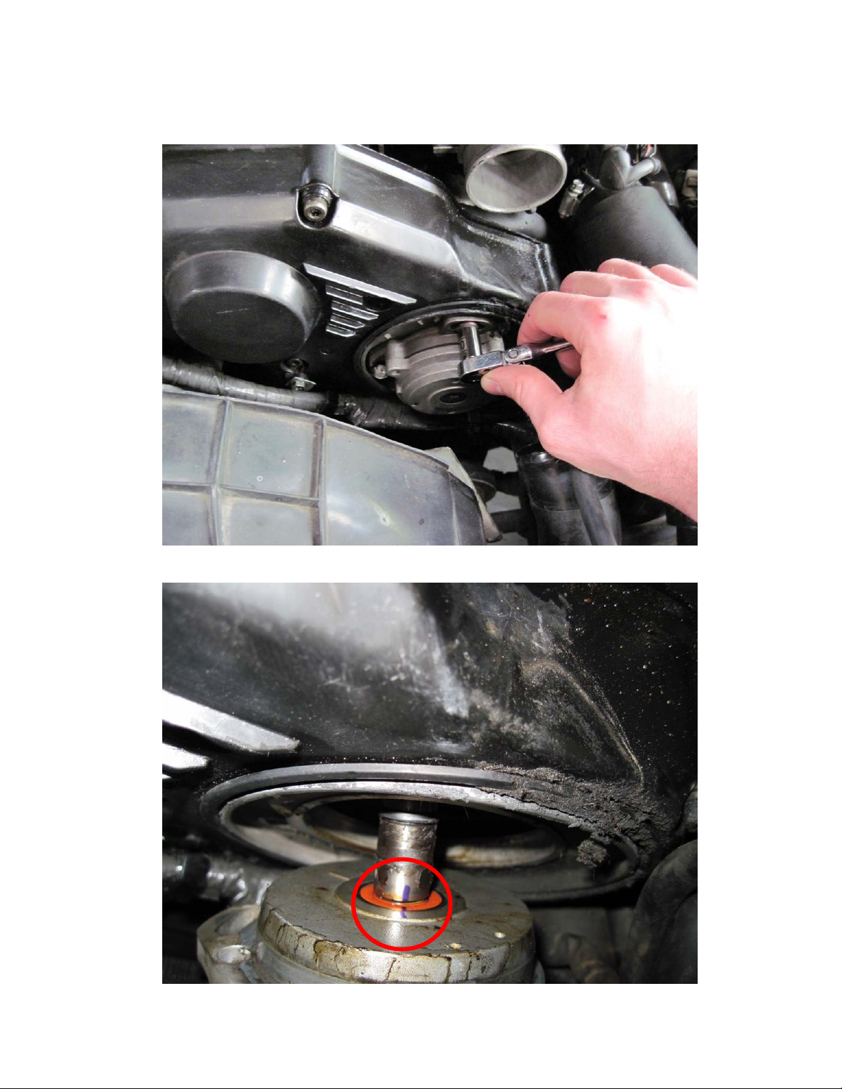
Remove intake tube obstructing access to the CAS sensor using an 8mm socket as shown
in figures 4 and 5. Figure 6 shows how access to the CAS sensor looks once the tube is
removed.
Figure 4: Removal of intake tube using 8mm socket
Page 4 of 25
Page 5
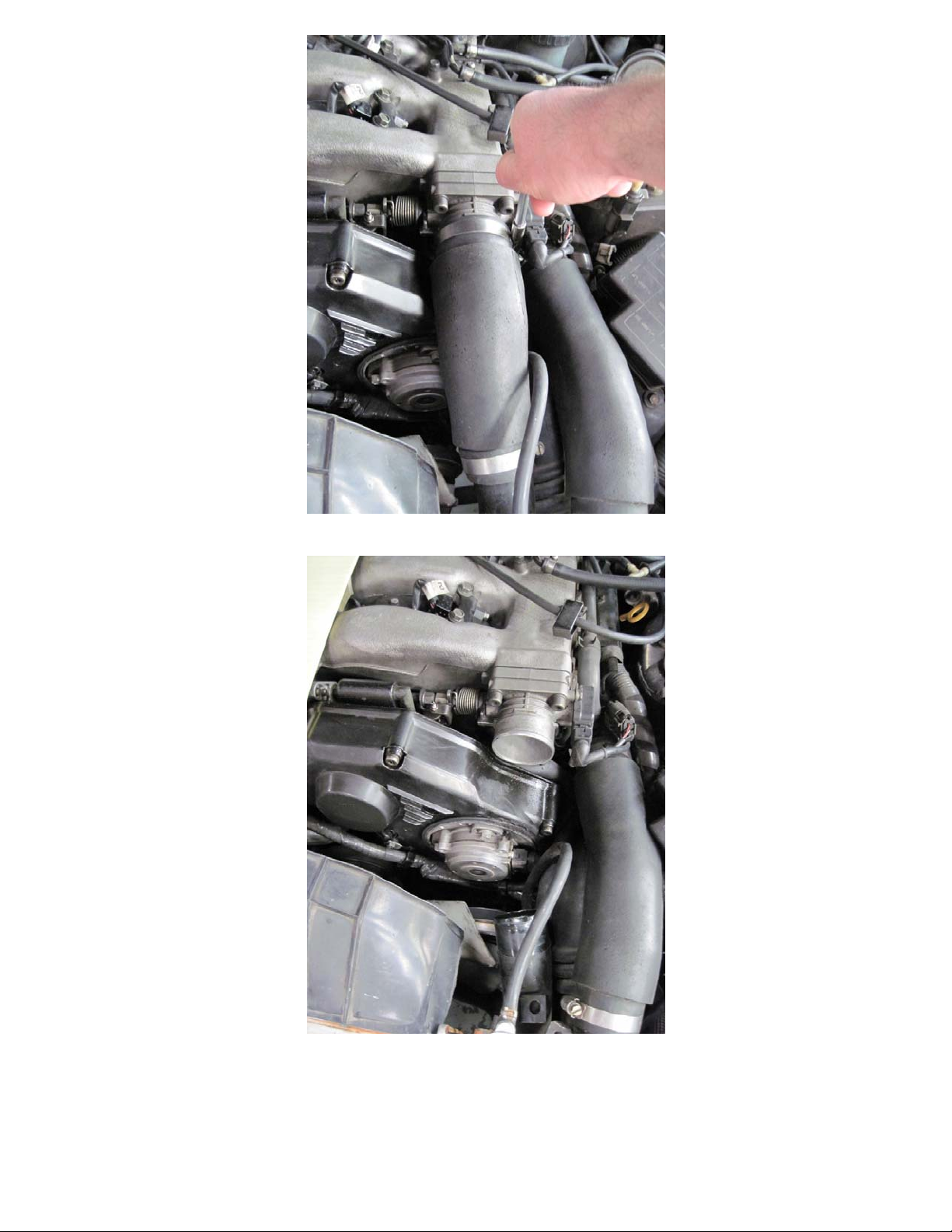
Figure 5: Removal of intake tube using 8mm socket
Figure 6: Intake tube removed to access CAS sensor
Page 5 of 25
Page 6

Mark the three bolts on the CAS sensor with your Sharpie as shown in figures 7 and
8 so that the sensor will go back into its original position upon reinstallation.
Figure 7: Marking position of CAS sensor
Figure 8: Marking position of CAS sensor
Page 6 of 25
Page 7

Remove clip that holds the harness to the CAS sensor using a pick and a pair of
needle-nose pliers as shown in figures 9 and 10. This may be done after removing
the CAS assembly, but is best done now.
Figure 9: Pry here to remove this clip
Figure 10: Remove clip with needle-nose pliers
Page 7 of 25
Page 8
Remove the three bolts on the CAS sensor using a 10mm socket as shown in figure 11.
Take care not to turn the sensor. Mark with your Sharpie so that the sensor can be
reinstalled correctly as shown in figure 12. Figure 13 shows the cam with the CAS
assembly removed. (If you turn the sensor by accident, make sure to align it with cam and
mark it)
Figure 11: Removal of 3 CAS sensor bolts using 10mm socket
Figure 12: Mark shaft relative to housing for correct reinstallation onto cam
Page 8 of 25
Page 9

Figure 13: CAS sensor removed
Remove the three screws holding the CAS assembly together using a ¼” flat
screwdriver (use the flat screwdriver since these screws are tightly installed, but soft)
as shown in figure 14.
Figure 14: Taking apart CAS assembly using number 2 Phillips screwdriver
Page 9 of 25
Page 10

Remove screws holding the seal cover onto the assembly using a ¼” flat screwdriver
as shown in figure 15.
Figure 15: Removing seal cover on CAS assembly using ¼” screwdriver
Screw in the M4x45mm cap screws so that plenty of threads are engaged and lightly
tap the three bolts evenly using a mallet so that the assembly will separate as shown
in figure 16. If prying between the two halves is necessary as shown in figure 17, be
extremely careful not to damage the sensor inside or the rubber seal.
Figure 16: Using cap screws and mallet to loosen/remove cover
Page 10 of 25
Page 11

Figure 17: Using prybar to remove cover
Remove the 3 screws holding the CAS sensor onto the assembly as shown in figure
18 as well as the rubber seal shown in figure 19. Make sure that you do not remove
the screws in figure 20 because this may render the CAS sensor useless.
Figure 18: Remove 3 screws holding sensor using ¼” flat screwdriver
Page 11 of 25
Page 12

Figure 19: Remove seal from CAS assembly
Figure 20: DO NOT REMOVE THESE SCREWS!
Page 12 of 25
Page 13

Mount the assembly in a vise placing the two ears that stick out of the cover shown in
figure 21 on the jaws being mindful of the plastic connector to the CAS sensor as
shown in figure 22.
Figure 21: Mounting CAS assembly in vise to separate from shaft
Figure 22: Mounting CAS assembly in vise to separate from shaft
Page 13 of 25
Page 14

Remove the shaft from the remaining half of the housing using a 3/8” pin punch as
shown in figure 23. Figure 24 shows the sensor separated from the housing.
Figure 23: Separation of shaft from housing using 3/8” pin punch and hammer
Figure 24: CAS sensor removed from housing
Page 14 of 25
Page 15

This step requires a lot of finesse or help from a friend to hold the shaft from falling
off the vise. Mark the star socket relative to the shaft and remove the pin holding the
star socket onto the shaft using a 1/8” pin punch as shown in figure 25.
Figure 25: Removal of pin using 1/8” pin punch
Remove the star socket with a ¼” flat screwdriver as shown in figure 26. Figure 27
shows the star socket removed with the small rubber seal that is inside it.
Figure 26: Removal of star socket using ¼” flat screwdriver
Page 15 of 25
Page 16

Figure 27: Star socket removed from CAS sensor
This is another step that requires a little finesse or a friend. Remove the remaining
bearing using a pair of pliers with flat jaws to have a firm grip on the shaft but be
narrow enough to fit in between the collar on the shaft and the bearing. Hit the pliers
with a mallet. Note how the shaft is placed into the vise in figure 28. Figure 29 shows
the bearing removed from the shaft.
Figure 28: Removal of bearing from shaft using pliers
Page 16 of 25
Page 17

Figure 29: Bearing removed from shaft
Using the number 2 Phillips screwdriver remove the screws holding the CAS disc
onto the shaft as shown in figure 30.
Figure 30: Removal of 2 screws on CAS disc using number 2 Phillips screwdriver
Page 17 of 25
Page 18

Figure 31 shows the shaft removed once the screws are removed. Mark the disc so
that you can identify how it was mounted for future reference. Carefully remove the
CAS disc from the sensor by rotating the disc in the direction of the large arrow
relative to the locating pin so that it will pull directly up over the pin in the direction of
the small arrow.
Figure 31: CAS disc screws and shaft removed
The original and AEM trigger discs must be aligned in the correct orientation since the
locating pin is slightly offset as shown in figure 32.
Figure 32: Comparison of original and AEM trigger discs
Page 18 of 25
Page 19

Install the AEM CAS sensor disc (AEM PN 35-8761) as shown in figure 33.
Figure 33: AEM trigger disc being installed
Reinstall the shaft onto the CAS sensor as shown in figure 34 and replace the screws on
the shaft with some thread locker as shown in figure 35.
Figure 34: CAS sensor shaft reinstallation
Page 19 of 25
Page 20

Figure 35: Screws for CAS shaft replaced
Reinstall bearing as shown in figure 36. Next add some grease or spray lube onto the oring that came off of the star socket that goes over the bearing and lightly hammer the star
socket on a flat surface so that you are only hammering the shaft until the hole for the pin
that holds the star socket lines up as shown in figure 37. A pin punch can be used to align
the hole for the pin if it is slightly off.
Figure 36: Bearing placement on CAS shaft
Page 20 of 25
Page 21

Figure 37: Hammering star socket to press on socket and bearing
Similar to the removal of the pin, the reinstallation of the pin requires hammering the pin
back into the hole on the star socket as shown in figure 38 Note: The socket must be
aligned relative to the shaft before performing this step.
Figure 38: Aligning the star socket retaining pin
Page 21 of 25
Page 22

Reinstall the screws that hold on the plastic CAS sensor with some threadlocker to the
metal housing taking extreme care not to bend the trigger disc. This can be accomplished
by lightly pulling the shaft as shown in figure 39.
Figure 39: Reinstallation of CAS sensor screws
Reinstall rubber seal for housing as shown in figure 40.
Figure 40: CAS rubber seal reinstalled
Page 22 of 25
Page 23

Reinstall 2nd CAS housing half making sure that the plastic connector and rubber seal are
aligned properly to avoid CAS sensor and disc damage. The housing should be able to be
pressed on by hand with even pressure around the whole assembly. Once together,
reinstall screws with threadlocker. See figure 41.
Figure 41: Housing cover reinstalled
Reinstall the plastic connector cover as shown in figure 42.
Figure 42: Connector cover reinstalled
Page 23 of 25
Page 24

Align the CAS sensor with the mark you made at the beginning of the instructions or
alternatively, look at the cam and align the sensor with the groove in the cam. Make sure
that the sensor is seated properly before reinstalling the bolts. See figure 43.
Figure 43: Reinstalling the CAS sensor
Align bolts with previously made markings and tighten as shown in figure 44.
Figure 44: Reinstalling CAS sensor bolts
Page 24 of 25
Page 25

Reattach the plastic connector to the CAS sensor after making sure the metal retaining
clip is present and installed correctly. See figure 45.
Figure 45: Replacing CAS sensor connector
Reinstall the intake tube in the reverse of removal.
Page 25 of 25
 Loading...