

Page 1

!
WARNING:
This installation is not for the tuning novice nor the PC illiterate!
Use this system with EXTREME caution! The EMS-4 allows for
total flexibility in engine tuning. Misuse of this product WILL
destroy your engine!
Installation of the EMS-4 must be performed by a qualified EFI
technician familiar with EFI sensors, actuators and wiring.
You should also visit the AEM EMS Tech Forum at
http://www.aempower.com
NOTE: AEM holds no responsibility for any engine damage that
results from the misuse of this product!
INSTALLATION AND TUNING GUIDE FOR:
EMS P/N 30-6905
EMS-4
PROGRAMMABLE ENGINE MANAGEMENT SYSTEM
This product is legal in California for racing vehicles only and should never be used on public
highways.
2205 W. 126TH STREET, UNIT A HAWTHORNE CA 90250
AEM PERFORMANCE ELECTRONICS
PHONE: 310-484-2322 FAX: 310-484-0152
http://www.aemelectronics.com
Page 1 of 279 EMS-4 Install and Tuning Guide_Rev 1.6
Page 2

Revision History
Version
Date
Modified Sections
Description
Initial Release, 1.0
12/27/10
1.1
12/28/10
Typical Idle Setup
Tab
Injectors section
Added example calculations
for Idle Frequency Settings
Clarified a section reference
1.2
12/28/10
Injection Phasing
Coil Phasing
Added details on Injector
Advance table
Added details on alternative
firing order setups
1.3
12/30/10
EMS-4 GPIOs
Added additional details to
example setups
1.4
1/4/11
Timing Pattern
Basics
Corrected error in diagram
1.5
1/10/11
Various
Fixed several minor
typographical errors
1.6
2/10/11
Internal Logging
Clarifications
1.7
3/23/11
Advanced Tuning
Added Switched Ign
Retard/Cut documentation
Page 2 of 279 EMS-4 Install and Tuning Guide_Rev 1.6
Page 3

Table of Contents
General Information ...................................................................................................................... 6
Electronics Warranty ..................................................................................................................... 6
Part 1 – EMS-4 Installation ........................................................................................................... 7
EMS-4 Basic Specifications ...................................................................................................... 7
Wire Harness Options ............................................................................................................... 7
ECU Terminations with Mini Harness, P/N 30-2905-0 ......................................................... 10
Electronic Wiring Conventions ............................................................................................. 16
Grounding ............................................................................................................................ 17
Power Requirements of the AEM EMS ................................................................................ 17
Use of Relays to Control Ancillary Devices ......................................................................... 17
Installation with Full Harness, P/N 30-3905-96 ....................................................................... 18
USB Connector .................................................................................................................... 18
CAN Connector .................................................................................................................... 19
Injectors ............................................................................................................................... 19
Coils / Electronic Ignition System Basics ............................................................................. 21
TPS (Throttle Position Sensor) ............................................................................................ 26
MAP Sensor ......................................................................................................................... 26
Air Temp Sensor .................................................................................................................. 27
Water Temp Sensor ............................................................................................................. 28
Crank Sensor ....................................................................................................................... 29
Cam Sensor ......................................................................................................................... 33
Vehicle Speed Sensor (VSS) ............................................................................................... 34
Part 2 – AEM Tuner .................................................................................................................... 37
Software Installation ................................................................................................................ 37
AEM Tuner .............................................................................................................................. 39
Basic Terminology ............................................................................................................... 40
Menu Items .......................................................................................................................... 42
Editing EMS Calibration Files .................................................................................................. 77
Editing Options Displays ...................................................................................................... 77
Editing 2D Table Displays .................................................................................................... 81
Editing Channel Displays ..................................................................................................... 89
Editing 3D Map Displays ...................................................................................................... 90
Page 3 of 279 EMS-4 Install and Tuning Guide_Rev 1.6
Page 4

Part 3 – Tuning Guide ................................................................................................................. 98
Background ............................................................................................................................. 98
Fuel Tuning General Concepts ............................................................................................ 98
Spark Tuning General Concepts ......................................................................................... 99
Calibration Setup ................................................................................................................... 100
Base Calibrations ............................................................................................................... 100
Timing Pattern Basics ........................................................................................................ 101
Fuel Phasing and Injector Setup ........................................................................................ 104
A more complex example .................................................................................................. 106
Ignition Phasing and Coil Dwell Discussion ....................................................................... 107
Set up RPM and Load axes ............................................................................................... 114
EFI Sensors ........................................................................................................................... 115
TPS (Throttle Position Sensor) .......................................................................................... 115
MAP (Manifold Pressure Sensor) ...................................................................................... 116
Air Temperature Sensor .................................................................................................... 119
Water Temp Sensor ........................................................................................................... 120
O2 (Oxygen) Sensors ......................................................................................................... 120
Knock Sensor .................................................................................................................... 125
Sensor Calibration ............................................................................................................. 126
Fuel System Setup ................................................................................................................ 134
Fuel Pump Setup ............................................................................................................... 134
Fuel Pump Sizing ............................................................................................................... 135
Fuel Pump Location ........................................................................................................... 136
Fuel Hoses and Routing .................................................................................................... 136
Fuel Delivery Hose Sizes ................................................................................................... 137
Fuel Filter and Fuel Rail ..................................................................................................... 137
Fuel Pressure Regulator and Pulse Dampener ................................................................. 139
Basic Tuning .......................................................................................................................... 142
Timing Pickup Confirmation ............................................................................................... 142
Noise .................................................................................................................................. 145
Ignition Synchronization ..................................................................................................... 146
Crank Fuel & Engine Start ................................................................................................. 148
Idle Air Control ................................................................................................................... 150
Page 4 of 279 EMS-4 Install and Tuning Guide_Rev 1.6
Page 5

Fuel Tuning ........................................................................................................................ 158
Acceleration/Deceleration Modifiers for Engine Fueling .................................................... 176
Ignition Tuning Theory ....................................................................................................... 182
Ignition Map ....................................................................................................................... 193
Ignition Trims ..................................................................................................................... 193
Vehicle Speed .................................................................................................................... 197
EMS-4 GPIOs .................................................................................................................... 199
Data logging ....................................................................................................................... 209
Advanced Tuning .................................................................................................................. 216
Boost Control ..................................................................................................................... 216
Knock Control .................................................................................................................... 231
Traction Control ................................................................................................................. 233
2Step Rev Limiter .............................................................................................................. 242
O2 Feedback ..................................................................................................................... 245
Nitrous Control ................................................................................................................... 252
Anti-Lag ............................................................................................................................. 256
Analog Input Switch ........................................................................................................... 259
Staged Injection ................................................................................................................. 260
Switched Ignition Retard/Cut ............................................................................................. 266
Glossary of Terms ................................................................................................................. 269
Index ...................................................................................................................................... 278
Page 5 of 279 EMS-4 Install and Tuning Guide_Rev 1.6
Page 6

General Information
READ AND UNDERSTAND THESE INSTRUCTIONS BEFORE ATTEMPTING TO INSTALL THIS
PRODUCT. VISIT THE AEM PERFORMANCE ELECTRONICS TECH SUPPORT FORUM AT
http://forum.aempower.com/forum/index.php ALL CURRENT SOFTWARE AND DOCUMENTATION
IS AVAILABLE ON THIS FORUM.
YOU MAY ALSO CONTACT AEM PERFORMANCE ELECTRONICS TECH SUPPORT AT 1-800-423-
0046 IF YOU HAVE ANY QUESTIONS.
Electronics Warranty
Advanced Engine Management Inc. warrants to the consumer that all AEM Electronics products
will be free from defects in material and workmanship for a period of twelve months from date of
the original purchase. Products that fail within this 12-month warranty period will be repaired or
replaced when determined by AEM that the product failed due to defects in material or
workmanship. This warranty is limited to the repair or replacement of the AEM part. In no event
shall this warranty exceed the original purchase price of the AEM part nor shall AEM be
responsible for special, incidental or consequential damages or cost incurred due to the failure
of this product. Warranty claims to AEM must be transportation prepaid and accompanied with
dated proof of purchase. This warranty applies only to the original purchaser of product and is
non-transferable. All implied warranties shall be limited in duration to the said 12-month
warranty period. Improper use or installation, accident, abuse, unauthorized repairs or
alterations voids this warranty. AEM disclaims any liability for consequential damages due to
breach of any written or implied warranty on all products manufactured by AEM. Warranty
returns will only be accepted by AEM when accompanied by a valid Return Merchandise
Authorization (RMA) number. Product must be received by AEM within 30 days of the date the
RMA is issued.
Please note that before AEM can issue an RMA for any electronic product, it is first necessary
for the installer or end user to contact the tech line at 1-800-423-0046 to discuss the problem.
Most issues can be resolved over the phone. Under no circumstances should a system be
returned or a RMA requested before the above process transpires.
AEM will not be responsible for electronic products that are installed incorrectly, installed in a
non-approved application, misused, or tampered with.
Any AEM electronics product can be returned for repair if it is out of the warranty period. There
is a minimum charge of $50.00 for inspection and diagnosis of AEM electronic parts. Parts used
in the repair of AEM electronic components will be extra. AEM will provide an estimate of repairs
and receive written or electronic authorization before repairs are made to the product.
Page 6 of 279 EMS-4 Install and Tuning Guide_Rev 1.6
Page 7

Part 1 – EMS-4 Installation
CPU Core:
16 bit / 40 MHz
Injector Drivers:
4 x Saturated (8 ohm minimum, High Impedance Only)
Coil Drivers:
4 x 0-5V Falling Edge Fire (do not connect directly to coil
primary)
GPIO Pins:
4 x 1.5A Low Side Output / 0-5V Analog Input / Switch Input
4 x 1.5A Low Side Output / 0-5V Analog Input / PWM output
O2 Sensor Input:
1 x 0-5V analog
Timing Sensor Inputs:
1 x VR (mag) Cam Input
1 x VR (mag) Crank Input
1 x Hall VSS Input
1 x Hall Crank Input
1 x Hall Cam Input
Knock Sensor Input
1x Programmable
Throttle Position Input
1 x 0-5V
Manifold Pressure Sensor
1 x 0-5V
Coolant Temperature Sensor
1 x analog
Inlet Air Temperature Sensor
1 x analog
USB
1 x EMS / PC Communication
CAN
1 x Programmable Send / Receive
Sensor Ground
1 x
5 Volt Reference
1 x
EMS-4 Basic Specifications
EMS-4 Specifications
Wire Harness Options
EMS-4 with 30-2905-96 Full Harness EMS-4 with 30-2905-0 Mini Harness
Page 7 of 279 EMS-4 Install and Tuning Guide_Rev 1.6
Page 8

Page 8 of 279 EMS-4 Install and Tuning Guide_Rev 1.6
Page 9

Page 9 of 279 EMS-4 Install and Tuning Guide_Rev 1.6
Page 10

Two partially assembled harness options are available for the EMS-4:
1. P/N 30-2905-96 EMS-4 Full Harness
2. P/N 30-2905-0 EMS-4 Mini Harness
Photographs and schematics for each are shown above. The Full Harness option is best suited
to applications where no factory harness exists or where modifications are so extensive, it is
easier to build a custom harness. This harness includes a fused power distribution center with
main relay. All circuits are pre-terminated at the ECU connector. All sensor input and actuator
output leads are grouped and clearly labeled. All power and ground splices are pre-configured.
All sensitive communications and CAN data stream circuits are pre-configured.
The Mini Harness option is best suited to applications where the factory harness is suitable as a
starting point for modifications. Like the fully populated harness, the mini version includes preterminated CAN data stream and communications circuits. It also includes primary power and
ground inputs. This is the minimum required for powering up the EMS and enabling
communications. All other harness terminations are the responsibility of the installer. A bag of
Delphi/Packard female terminals is included for terminating all circuits at the main ECU
connector.
Installers choosing the Mini Harness option should refer to the Full Harness schematic
above and the EMS-4 System Diagram that shows an example of a complete system
design.
ECU Terminations with Mini Harness, P/N 30-2905-0
To following steps illustrate how to open the ECU connector backshell so additional circuits can
be added.
Begin by cutting the strain relief tie
wrap holding the terminal bag as
shown.
Page 10 of 279 EMS-4 Install and Tuning Guide_Rev 1.6
Page 11

Using a sharp pick or
probe, push in on the
locking tabs holding the
outer retainer.
Remove the retainer.
Page 11 of 279 EMS-4 Install and Tuning Guide_Rev 1.6
Page 12

Use pick to pry open the
retaining tabs holding the
backshell halves together.
Open the shell to expose
the cavities.
Page 12 of 279 EMS-4 Install and Tuning Guide_Rev 1.6
Page 13

To remove a terminal,
carefully pry up on the
retaining clip. Be careful
as the clips can break if
bent too far.
To add a new circuit,
insert the terminal from
the back as shown until it
clicks into place.
Page 13 of 279 EMS-4 Install and Tuning Guide_Rev 1.6
Page 14

Showing terminal fully
seated.
Following is the proper tool for use with the Delphi Micro Pack terminals used in the ECU main
connector.
Delphi Part No: 12070948
Application: Unsealed Micro-Pack 100, Female only
Core and Insulation
Cable Range (mm2): 2.0-0.35
Page 14 of 279 EMS-4 Install and Tuning Guide_Rev 1.6
Page 15

The tool is available in many places. One is shown below. Web address –
http://www.mouser.com AEM recommends using the proper tool for all ECU terminations.
Image shows a properly crimped
terminal. Top View.
Page 15 of 279 EMS-4 Install and Tuning Guide_Rev 1.6
Page 16
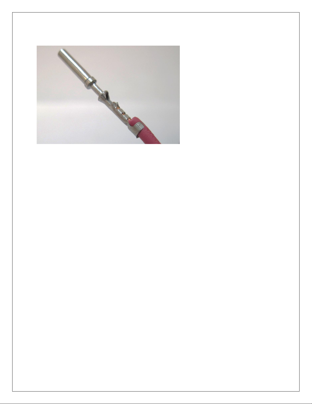
Side View. After crimping, be sure
to do a pull test to make sure the
terminal is properly installed.
Electronic Wiring Conventions
A proper wiring job includes proper termination of the wire at the sensor. The wire terminal end
must be moisture tight where it plugs into the sensor and it must have strong, electrically sound
terminals. The preferred method of securing a wire to a terminal is to use a crimp terminal with
NO solder. It is important to use the proper crimping tool for sound terminal construction.
Plastic terminal plugs must have moisture tight seals. Inspect each plug to make sure the seals
are in place. Also, before the plug is installed on the sensor, apply a dab of di-electric grease in
the terminal slots to further aid in corrosion resistance.
If a splice into a wire must be made and no solder-less terminals are available, then you must
properly solder the splice.
Noise can be a serious problem and can cause intermittent misfiring of the engine. Every
precaution should be taken to prevent interference to the ECU‟s operation. Resistive plug leads
are REQUIRED, and shielded cables from the crank and cam angle sensor inputs are highly
recommended. All racing AEM EMS wire harnesses come with properly shielded cables and are
color coded for easy identification of circuits. They are also shrink wrapped for abrasion
protection. The crank and cam angle sensor wire has a bare wire running down the length of it.
It is NOT terminated at the sensor end of the cable because we ground it at the plug end of the
harness. DO NOT GROUND THIS WIRE! This will cause a condition called ground looping
and will remove any noise protection the cable has.
To eliminate or reduce the chance of EMI, wires that carry high current must run in twisted pairs.
An example of this would be the power leads from a multiple spark ignition system. These
ignition systems can carry up to 100 amps for a couple milliseconds at the time of discharge,
which induces a strong magnetic field in close proximity of the wires.
Page 16 of 279 EMS-4 Install and Tuning Guide_Rev 1.6
Page 17

The routing of the wire loom is critical to EFI system performance and safety. The following
safety considerations should be made when installing the wire loom:
Heat protection: the loom should be placed away from or insulated from sources of heat.
The obvious item(s) that should be avoided are the exhaust manifolds, EGR delivery
tubes, and turbochargers. If it is absolutely necessary to route a wire in close proximity
to any of these items, then a suitable insulator must be used.
Noise suppression: do not route wires near the HT leads. For coil- on-plug ignition
systems this is not as critical.
Moving component protection: route wires away from moving components such as fans,
the blower belt, or the throttle linkage. Also, make sure the wires are not under any
strain when the engine is at full deflection on the motor mounts (we have seen map
sensor wires disconnect while under full acceleration because the motor mounts were
bad).
Never have the wires in exposed bundles throughout the engine compartment. A
professional harness has shrink tube over it to resist abrasion and chemical damage to
the wire loom.
Grounding
The ECU must have an electrically secure ground connection, which means that the battery
negative must be properly grounded to the chassis AND engine. The ground wire, whether it is
from the battery or to the chassis and engine, must have perfect electrical conductivity. This
means that there must not be any paint or rust under the wire terminal. Make sure that when
you install the ground wire there is bare metal exposed where the wire contacts the vehicle
component. To prevent rust build up, we recommend applying a protective layer of dielectric
grease, such as Standard Ignition SL-4, to the bare metal surface. The ground wire must be at
least the same gauge as the power lead to the ECU. We also recommend that the ground wire
be as short as possible.
Power Requirements of the AEM EMS
The AEM EMS requires a minimum supply voltage of 10V or greater to run. We recommend
that the ECU be supplied with 13.8V nominal operating voltage. Ensure that the vehicle‟s
charging system is in perfect operating condition prior to installing the AEM EMS.
Use of Relays to Control Ancillary Devices
Relays are remote switching devices that are used to isolate a device from the ECU‟s circuitry to
reduce noise and power constraints on the ECU. Typical devices that are powered by a relay
are:
Fuel Pump
Variable Valve Control
Oxygen Sensor Heater
ECU power
Nitrous Oxide solenoids
Page 17 of 279 EMS-4 Install and Tuning Guide_Rev 1.6
Page 18

Noise can be caused by the electric motor in a fuel pump, which if connected directly to the
ECU, may feed back into the circuit board ground plane. In the case of a fuel pump, the typical
amperage required to run the pump is 10A or more depending on its size. The driver in the
ECU that sends the command to run the fuel pump is only capable of supplying 1.5A, and
clearly this type of load on the driver would cause it to burn out. There are drivers that can
handle larger currents but cost, size, heat dissipation, and noise problems prevent their use.
Typical relays in use today are capable of carrying 40A. A relay has an electromagnet
inside it that is used as a switch. This electromagnet, or switch, is used to position a
contact within the relay that is capable of carrying high current. There are typically four
or five terminals on the base of a relay. These terminals can be wired in several ways to
achieve different results. Refer to the EMS-4 System Schematic for common wiring
schemes used with relays.
Installation with Full Harness, P/N 30-3905-96
For the following section, please refer to the EMS-4 System Diagram for more
information. It shows a schematic representation of a properly designed system using
the fully populated harness.
NOTE: The columns in the connection tables below labeled “WIRE” refer to the wire
gauge recommended for the harness.
USB Connector
USB Connector
Page 18 of 279 EMS-4 Install and Tuning Guide_Rev 1.6
Page 19

A high quality over-molded termination is included for USB communications. Plug one end of a
standard USB extension cable (included) into the harness connector and the other end into an
open USB port on the PC. Communications is possible only when the EMS is powered up.
CAN Connector
CAN Connector
A compact pre-terminated connector is included for use with AEM CAN enabled devices.
Injectors
Injector Basics
A fuel injector is a valve that can be opened and closed very quickly. To open the valve, current
must flow through a solenoid contained in the upper part of the injector assembly. The EMS-4
triggers the injector by providing a ground path to the negative terminal. Fused power is
provided to the other terminal from the harness.
WARNING! – The EMS-4 is compatible with high impedance injectors only. For direct
drive operation, injector coil resistance must be greater than 8 ohms. Low impedance
injectors can be used if a suitable ballast resistor box or Peak and Hold Driver module is
used such as AEM P/N 30-2710.
To determine the size of the injectors, the total engine power must be estimated or known. The
fuel pump calculations and BSFC information mentioned in the Fuel Pump Sizing section on
page 135 provides a good understanding of the fuel requirements for an engine. The following
equation will allow you to determine the requirements of your injectors:
Page 19 of 279 EMS-4 Install and Tuning Guide_Rev 1.6
Page 20

((Power x BSFC) x (1 + Safety Margin))/Number of Injectors = pounds/hour
Name
Wire
Wire
Color
Stamping
Injector #1
22
Orange
INJ 1
Injector #2
22
Orange
INJ 2
Injector #3
22
Orange
INJ 3
Injector #4
22
Orange
INJ 4
Fused Injector Power
14
Red
INJ POWER
An example of this equation is:
6 CYL. engine rated at 500 hp on gasoline using moderate boost with a 15% safety margin on
the injector
500 x .625 = 313 lbs/6 = 52 lbs/hr/ injector. 52 x 1.15=60lbs/hr/ injector
If we take the flow of the injector (60 lbs/hr) and multiply it by the number of cylinders (6), we
arrive at a total of 360 lbs/hr of flow. As you can see, the fuel pump described in the fuel pump
sizing section referenced above has enough capacity to feed the engine with a little room to
spare.
It is a good idea to know the maximum operating pressure of the fuel injectors. In some cases
the fuel injector will not open if the fuel pressure exceeds the design limit of the injector. Also, at
the higher pressures the injector fuel flow may become non-linear and cause inconsistent fuel
delivery, usually creating a lean condition. Most injectors can withstand up to 70 psi. Many of
the pintle style injectors can withstand higher pressure.
In the fuel injector sizing, always use a safety margin between 15-20%.
Harness Connections
Injector Harness Connections
INJ1 – Connect to 1st injector to fire.
INJ2 – Connect to 2nd injector to fire.
INJ3 – Connect to 3rd injector to fire.
INJ4 – Connect to 4th injector to fire.
INJ POWER – Fused injector power. Splice required number of power leads and distribute to
each injector.
Page 20 of 279 EMS-4 Install and Tuning Guide_Rev 1.6
Page 21

AEM kit P/N 30-2020 (Optional) Bosch Style Injector Connector Kit contains the parts to
assemble 4 injector connectors. The kit contains Four Bosch style female injector connectors
and 10 contacts (2 extra contacts are included for spares).
IMPORTANT!
The contacts are “Pull to Seat” meaning you must feed the wire through the connector housing
BEFORE you crimp on the contacts. The wire is then pulled back into the housing and the
contact locks in place. The contact cannot be inserted or removed from the rear (wire side entry)
of the housing.
Contacts (10 Included)
Plating Tin Plated
Cable Range 1.00 - 0.05 mm2
Outside Cable Diameter 2.40 - 2.03 mm2
Temperature Range -40 to 125 C
Resistance in mOhms at 20 mV > 10.0 Ohms
Voltage Drop in mV per amp > 3.0 Ohms
Housing (4 Included)
Color Black
Cavities or Contacts 2
Gender Female
Temperature Range -40 to 125 C
Resistance at 20 mV > 10.0 mOhm
Voltage Drop per amp > 3.0 mV
Exterior Dimensions 27.8L X 29.6W X 20H
Seating Process Pull To Seat
Coils / Electronic Ignition System Basics
An ignition coil is charged when current flows through the primary side of the coil. A coil driver
is required to sink the current and dissipate the heat generated during operation. The coil
outputs from the EMS-4 are used to trigger the drivers. The drivers can either be contained
within the coils themselves or they can be contained within a stand-alone device installed
between the EMS-4 and the coils.
There are several different types of ignition systems in use on modern cars.
They are:
Distributed spark using a single coil and a distributor for all cylinders.
Wasted spark using one coil for two cylinders.
Direct Fire using one coil on plug of each cylinder.
Distributed Spark
Distributed spark systems have been around the longest. As the name implies, the spark is
distributed to the plugs via a coil output to a rotor, then through the distributor cap to the
appropriate plug via a high-tension (HT) lead. This is the most complex system because of the
relationship that has to be maintained between the firing point, rotor to cap terminal angle, and
Page 21 of 279 EMS-4 Install and Tuning Guide_Rev 1.6
Page 22

engine position. Distributed spark systems also rely on a mechanical link between the engine
Name
Wire
Wire
Color
Stamping
Coil 1 Output
22
Dk Blue
IGN 1
Coil 2 Output
22
Dk Blue
IGN 2
and ignition output, which adds another dimension of unreliability-and to a minor extentinaccuracy in timing. In addition to these problems, distributed spark systems typically produce
the least intense spark of all ignition systems. The time to achieve full charge diminishes as
engine speed increases; therefore the coil charge is reduced as a function of RPM. In spite of
the potential problems with distributed spark systems, they have been used successfully for
many years on high-performance engines. Distributed spark ignition systems respond well to
spark amplification within their design limits.
Wasted Spark
Wasted spark systems employ one coil for two cylinders. The term “wasted spark” comes from
the fact that each plug fires every engine revolution. On a 4-cycle engine, the piston is at Top
Dead Center (TDC) two times for every cycle; once for firing and again during the overlap
phase. The wasted spark coil fires one plug Before Top Dead center (BTDC) and another plug
just before the overlap phase (at the latest part of the exhaust stroke before the exhaust valve
closes). Wasted spark systems have a higher potential for spark intensity because the duty of
charging and discharging is split between the coils, which allows for more charge time per coil.
Additionally, wasted spark systems build up less heat in the coil, making it more reliable.
Wasted spark systems have been in use since the mid 80‟s on GM cars and on motorcycles for
considerably longer than that. There are no moving parts, no complicated relationships with a
cap and rotor to maintain, and they deliver very accurate spark timing. Furthermore, multichannel spark amplification systems to enhance spark duration or intensity are available for
wasted spark ignition systems.
Direct Fire
Direct fire systems employ one coil on each spark plug and is the most reliable system used
today, (this type of system is used on most modern cars). Each coil fires sequentially in the
cylinder firing order. The charge time for each coil is twice as long as those of a wasted spark
system, which allows direct-fire, coil manufacturers to build compact, lightweight coils that retain
sufficient spark energy. There are no moving parts to wear out and no HT leads that will
deteriorate. The lack of HT leads in direct fire systems is a major advantage for an EFIequipped car because there is a very low incidence of noise due to leaking or improperly routed
wires. There have been incidences of the terminal from a direct-fire coil (that attaches to the
spark plug) cracking and subsequently causing Radio Frequency Interference (RFI) or “noise” to
the ECU. This will cause engine operation problems, but it should be noted that these cases
are extremely rare.
Harness Connections
Coil Harness Connections
Page 22 of 279 EMS-4 Install and Tuning Guide_Rev 1.6
Page 23

Coil 3 Output
22
Dk Blue
IGN 3
Coil 4 Output
22
Dk Blue
IGN 4
Fused Coil Power
14
Red
COIL PWR
Coil Ground
14
Black
PWR GND
Warning! - The ignition outputs from the EMS-4 are not designed to trigger an ignition
coil directly. Connecting them to a coil that does not contain a built-in driver will damage
the EMS-4. Coils without built-in drivers typically have only two pins on the connector.
Coils with built-in drivers typically have 4 or more pins on the connector. If you are not
sure what kind of ignition coils you have, contact AEM tech support for help.
IGN 1 – Connect to 1st coil driver to fire.
IGN 2 – Connect to 2nd coil driver to fire.
IGN 3 – Connect to 3rd coil driver to fire.
IGN 4 – Connect to 4th coil driver to fire.
COIL PWR – Fused coil power. Splice required number of power leads and distribute to each
coil.
PWR GND – Ignition power ground.
AEM Kit P/N 30-2840 (Optional) Four Channel Coil Driver is custom manufactured to AEM‟s
specifications by HÜCO Electronic GmbH in their ISO 9001 facility in Germany. It has been
specially designed by AEM for driving the high power dwell controlled ignition coils commonly
found on performance engines.
The 30-2840 Kit contains:
Four Channel Coil Driver
Five Pin Mating Connector
Four Pin Mating Connector
10 Terminals & Wire seals (one extra of each as a precaution)
Mounting hardware
Thermal Grease
Page 23 of 279 EMS-4 Install and Tuning Guide_Rev 1.6
Page 24

Coil Driver
Connect to
ECU Coil 1 Output
EMS-4 harness, IGN 1
ECU Coil 2 Output
EMS-4 harness, IGN 2
ECU Coil 3 Output
EMS-4 harness, IGN 3
ECU Coil 4 Output
EMS-4 harness, IGN 4
Ground
EMS-4 harness, PWR GND
Coil 1 Negative Terminal
Coil 1 Negative Terminal
Coil 2 Negative Terminal
Coil 2 Negative Terminal
Coil 3 Negative Terminal
Coil 3 Negative Terminal
Coil 4 Negative Terminal
Coil 4 Negative Terminal
AEM Four Channel Coil Driver P/N 30-2840
Four Channel Coil Driver Connections
Coil Driver Connections
CDI Installations
The ignition outputs from the EMS-4 are considered a falling edge fire signal where signal high
is dwell time. A coil driver will invert the signal from the EMS-4 pulling the signal low (ground)
and allowing current to flow through the coil primary windings. Some CDI ignition boxes are
only capable of triggering on the “rising edge” or “Points Trigger” signal. These systems will still
require an in-line coil driver to invert the ignition output to fire on the correct edge. The AEM
Twin Fire CDI system P/N 2820 (8 channel) and 2821 (4 channel) can be configured to fire on
either a rising or falling edge. Applications using an AEM Twin Fire will not require an in-line coil
driver. Contact your CDI manufacturer for more information.
Page 24 of 279 EMS-4 Install and Tuning Guide_Rev 1.6
Page 25

Signal comparison – before and after coil driver
DWELL
DWELL
FALLING
5V
GND
IGNITION OUTPUT FROM EMS TO COIL DRIVER OR CDI
IGNITION OUTPUT AFTER COIL DRIVER
DWELL
DWELL
RISING EDGE
12V
GND
EDGE FIRE
FIRE
Page 25 of 279 EMS-4 Install and Tuning Guide_Rev 1.6
Page 26

Name
Wire
Wire
Color
Stamping
+5.0 volts, Vcc
22
Red
VCC
Throttle Position Sensor
22
White
THROTTLE
Sensor Ground
22
Black
SIG GND
Name
Wire
Wire
Color
Stamping
+5.0 volts, Vcc
22
Red
VCC
Manifold Pressure
Sensor
22
White
MAP
Sensor Ground
22
Black
SIG GND
TPS (Throttle Position Sensor)
Harness Connections
TPS Harness Connections
VCC – Connect to sensor 5 volt reference
THROTTLE – Connect to sensor signal
SIG GND – Connect to sensor ground
MAP Sensor
Harness Connections
MAP sensor harness connections
VCC – Connect to sensor 5 volt reference
MAP – Connect to sensor signal
SIG GND – Connect to sensor ground
Optional AEM MAP Sensor Listing:
AEM P/N 30-2130-30 “MAP Sensor Kit, 2 BAR”
Typically used to measure intake, air box and crankcase pressures.
AEM P/N 30-2130-50 “MAP Sensor Kit, 3.5 BAR”
Typically used to measure intake & exhaust back pressures.
Page 26 of 279 EMS-4 Install and Tuning Guide_Rev 1.6
Page 27
AEM P/N 30-2130-75 “MAP Sensor Kit, 5 BAR”
Name
Wire
Wire
Color
Stamping
Inlet Air Temp Sensor
22
White
AIR TEMP
Sensor Ground
22
Black
SIG GND
Typically used to measure intake & exhaust back pressures.
Air Temp Sensor
Harness Connections
Air Temperature Sensor Harness Connections
AIR TEMP – Connect to sensor signal
SIG GND – Connect to sensor ground
AEM P/N 30-2010 (Optional) Air Temp Sensor kit is specifically designed for temperature
measurements in automotive systems. The kit contains One GM style temperature sensor, one
“6” Flying Lead” mating connector assembly and a weld in aluminum bung.
Air Temperature Sensor Diagram
Housing Material: Brass with 3/8” NPT Thread (Torque to 25 Ft-Lbs)
Elec. Termination: Integral weatherproof connector, Includes mating connector with 6” leads,
18 AWG.
Wiring to your EMS: Polarity does not matter. Connect one wire to harness AIR TEMP lead
and the other to harness SIG GND lead.
Page 27 of 279 EMS-4 Install and Tuning Guide_Rev 1.6
Page 28

Name
Wire
Wire
Color
Stamping
Coolant Temp Sensor
22
White
COOLANT
Sensor Ground
22
Black
SIG GND
Water Temp Sensor
Harness Connections
Water Temperature Sensor Harness Connections
COOLANT – Connect to sensor signal
SIG GND – Connect to sensor ground
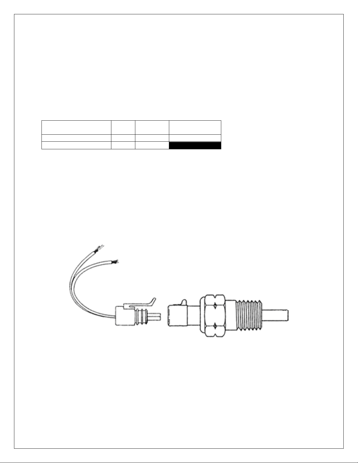
AEM P/N 30-2011 (Optional) Water Temp Sensor kit is specifically designed for temperature
measurements in automotive systems. The kit contains One GM style temperature sensor, one
“6” Flying Lead” mating connector assembly and a weld in aluminum bung.
Water Temperature Sensor Diagram
Housing Material: Brass with 3/8” NPT Thread (Torque to 25 Ft-Lbs)
Elec. Termination: Integral weatherproof connector, Includes mating connector with 6” leads,
18 AWG.
Wiring to your EMS: Polarity does not matter. Connect one wire to harness COOLANT lead
and the other to harness SIG GND lead.
Page 28 of 279 EMS-4 Install and Tuning Guide_Rev 1.6
Page 29

Crank Sensor
Crank Sensor Basics
The crank sensor is used to calculate engine speed, ignition timing and injection phasing
angles. It senses a toothed wheel (reluctor wheel, reluctor ring, etc.) and converts this pattern
into a voltage/frequency signal that the EMS uses for basic calculations. Either on its own, or
combined with the cam position sensor, it is the most important input to the system. There are
two basic types of crank sensors, variable reluctance (VR or “mag”) and hall-effect.
VR Sensor raw voltage signal
Page 29 of 279 EMS-4 Install and Tuning Guide_Rev 1.6
Page 30

Hall Effect voltage signal
The internal circuitry on the EMS is different depending on what type of sensor is being used.
Note that there are two different inputs on the EMS for crank and cam position. One for a Hall
Effect type pickup. The other for a VR or “mag” pickup.
The EMS-4 crank sensor VR inputs go through a signal conditioning chip on the circuit board
that converts the raw (zero crossing) signal into a clean 0-5V square wave signal as shown
below. The signal conditioning circuit will invert the significant edges of the raw signal. The
consistent edge of the raw signal in the example below is the rising edge. The conditioning
circuit inverts the signal and creates a falling significant edge.
Page 30 of 279 EMS-4 Install and Tuning Guide_Rev 1.6
Page 31

Internal Signal Conditioning Example
Shows signal conditioning with
edge invert on typical “missing
tooth” style VR crank sensor pattern
Page 31 of 279 EMS-4 Install and Tuning Guide_Rev 1.6
Page 32

Shows signal conditioning with edge
invert on typical evenly spaced VR
crank pattern.
Internal Signal Conditioning Detail
All VR Crank Sensor inputs to the EMS-4 must be connected such that the rising edge of the
raw sensor signal is the consistent zero crossing edge as shown in the examples above.
Failure to do this could result in misfires or ignition timing inaccuracies. Verify data with an
oscilloscope or contact your sensor manufacturer to verify polarity. The crank inputs to the
EMS-4 are contained within a black shielded cable assembly as shown below. Refer to the
EMS-4 System Diagram for more information.
Crank Sensor Input Cable End
Page 32 of 279 EMS-4 Install and Tuning Guide_Rev 1.6
Page 33

Harness Connections
Crank Sensor Ground
28
White
Crank Sensor Mag Input
28
Green
Crank Sensor Hall input
24
Black
+12 volts
24
Red
Cable Shield
---
Crank Sensor Harness Connections
Crank Sensor Mag Input, Green – Connect to VR (+) signal (rising edge zero cross). Not used
for Hall sensor configurations.
Crank Sensor Hall input, Black – Connect to Hall sensor signal. Not used for VR sensor
configurations.
+12 volts, Red – Connect to Hall sensor reference voltage. Not used for VR sensor
configurations. Insulate if not using (hot at key-on).
Crank Sensor Ground, White – Connect to Crank sensor VR (-) or Hall sensor signal ground
Cam Sensor
Cam Sensor Basics
The cam sensor is used to calculate engine position. It is necessary for sequential fuel
calculations. It senses a toothed wheel (reluctor wheel, reluctor ring, etc.) and converts this
pattern into a voltage/frequency signal that the EMS uses for basic calculations. Combined with
the crank position sensor, it is one of the most important inputs to the system. There are two
basic types of cam sensors, variable reluctance (VR or “mag”) and hall-effect.
All VR Cam Sensor inputs to the EMS-4 must be connected such that the rising edge of the raw
sensor signal is the consistent zero crossing edge as shown in the examples above. Failure to
do this could result in misfires or ignition timing inaccuracies. Verify data with an oscilloscope or
contact your sensor manufacturer to verify polarity. The crank inputs to the EMS-4 are
contained within a black shielded cable assembly as shown below. Refer to the EMS-4
System Diagram for more information.
Page 33 of 279 EMS-4 Install and Tuning Guide_Rev 1.6
Page 34

Cam Sensor Ground
28
White
Cam Sensor Mag Input
28
Green
Cam Sensor Hall
24
Black
+12 volts
24
Red
Cable Shield
---
Cam Sensor Input Cable End
Harness Connections
Cam Sensor Harness Connections
Cam Sensor Mag Input, Green – Connect to VR (+) signal (rising edge zero cross). Not used
for Hall sensor configurations.
Cam Sensor Hall, Black – Connect to Hall sensor signal. Not used for VR sensor
configurations.
+12 volts, Red – Connect to Hall sensor reference voltage. Not used for VR sensor
configurations. Insulate if not using (hot at key-on).
Cam Sensor Ground, White – Connect to Crank sensor VR (-) or Hall sensor signal ground
Vehicle Speed Sensor (VSS)
Vehicle Speed Sensor Basics
Page 34 of 279 EMS-4 Install and Tuning Guide_Rev 1.6
Page 35

The vehicle speed sensor must be a hall-effect device. It is used to detect wheel speed for use
Name
Wire
Wire
Color
Stamping
VSS Ground
22
Black
PWR GND
VSS Hall Input
22
White
VSS
+12.0 volts
22
Red
PWR
in various EMS-4 software functions.
Harness Connections
Vehicle Speed Sensor Harness Connections
PWR GND – Connect to vehicle speed sensor ground pin.
VSS – Connect to vehicle speed sensor signal pin.
PWR – Connect to vehicle speed reference voltage pin.
Page 35 of 279 EMS-4 Install and Tuning Guide_Rev 1.6
Page 36

DO NOT CONNECT
DIRECT TO BATTERY
Fuel Pump and Idle Air Control Example Circuits
The example above shows proper wiring design for inductive loads like fuel pump relays and
idle air control/boost control solenoids. Note that simple on/off type outputs from the EMS-4 can
be connected to any GPIO output but Pulse Width Modified (PWM) circuits such as those used
for idle control or boost control must be connected to GPIO 5 – 8, pins 14 – 17 on the 36 way
ECU connector. Note that the EMS-4 does not support Stepper Motor idle air control
valves. Do not connect the power side of any actuator (relay, solenoid, etc.) direct to the
battery. Only use switched, fused power as shown above. Refer to the EMS-4 System
Diagram for more information.
Page 36 of 279 EMS-4 Install and Tuning Guide_Rev 1.6
Page 37

Part 2 – AEM Tuner
Software Installation
All current AEM Tuner software installations are available for download from the AEM
Performance Electronics Forum at:
http://forum.aempower.com/forum/index.php
All Software Downloads Link
Click on the All Software & Firmware Downloads forum.
Software Downloads Link
Next click on the AEM Performance Electronics – All Software & Firmware Downloads forum
Software Downloads Link
Next click on the link shown above to reach the official download page. Note that you can
subscribe to this thread to be notified when software updates are released.
Page 37 of 279 EMS-4 Install and Tuning Guide_Rev 1.6
Page 38

Software Installation Revision Notes Example
All current software releases will include a set of revision notes describing feature changes or
additions since the last update.
Page 38 of 279 EMS-4 Install and Tuning Guide_Rev 1.6
Page 39

Software Installation Instructions
Follow the Installation Instructions as outlined above.
After the software installation is complete, click on the AEM Tuner icon to launch the application.
AEM Tuner Shortcut
AEM Tuner
When AEM Tuner launches, the application will begin with a window similar to the one below:
Page 39 of 279 EMS-4 Install and Tuning Guide_Rev 1.6
Page 40

AEM Tuner Environment
Basic Terminology
Calibration File – The calibration file is what the tuner modifies and will be specific to the engine
setup.
Options – Single values that are set by the user to change the operation of an EMS.
Channels - Channels are data for viewing and logging. They are a window to the engine. They
tell you everything the engine is doing and what all of the sensors are seeing. This window is
one of the most valuable tools in helping to tune the engine.
Tables – Tables are two dimensional data sets that define one value as a function of another.
Maps – Maps are three dimensional data sets that define one value as a function of two others.
Tabs – Tabs are screen templates that the user can create and edit to group sets of calibration
data as needed.
Workspace – User defined AEM Tuner configuration settings that include in part: Basic
application preferences, the display settings, the number of tabs displayed and the tab
configuration, color preferences, unit preferences, hot keys, etc.
Page 40 of 279 EMS-4 Install and Tuning Guide_Rev 1.6
Page 41

Item Explanations - Item Explanations provide a brief
description of what the currently selected in the currently
selected Display does, or is used for. So, for example, if the
selected Display was an Options Display, the Item
Explanation would describe the selected Option with that
selected Options Display. For Calibration items (Options
and Tables) this explains how the ECU uses that item to
accomplish a function. For Log items (Channels) this
explains what the value represents to the ECU.
Function Explanations - Function Explanations provide an
in depth explanation of the way Options, Tables and
Channels work together in the ECU to accomplish a
function. Here a function just means anything that the ECU
needs to control. So, for example, firing the fuel injectors is
a function, or controlling a boost control solenoid is a
function. Function explanations are associated with the
selected Display, so selecting a Display is the only way to
change the Function Explanation displayed.
Links - Function Explanations can contain links to the
Calibration and Log items they refer to (Options, Tables,
and Channels). Links are indicated with blue underlined
text, just as the standard hyperlinks in a web browser are.
When the user clicks on a link the item (either Calibration or
Log) the link references will be added to the appropriate
Display on the current Display Sheet and selected, giving it
focus. If that item already exists in a Display on the current
Display Sheet, then the item will just be selected. So, for
example, if the user clicks a link representing the "WG
Base Duty” map (as seen in example of the left) the 3D
Map Display containing that table would be opened (unless
it already existed on the Sheet) and that Display would
become selected.
Option links are treated differently from Table and Channel
links. Instead of just displaying the name of the Option in
the link, its current value from the loaded Calibration is
used, to provide an even more meaningful description of
how your particular car is setup. So if a link is simply a
number, it is an Option link. It can still be clicked just as
Table and Channel links are, and the referenced Option will
be displayed and selected.
Page 41 of 279 EMS-4 Install and Tuning Guide_Rev 1.6
Page 42

Menu Items
Following is a basic description of each menu function.
FILE
Open Calibration - Opens a previously saved calibration file
Open Last EMS Calibration – Opens the last calibration file saved in memory
Open Recent Calibration – Displays a list of recent opened calibrations files. Choose one to
open.
Save Calibration – Saves currently loaded calibration file with the same file name. Only active
when a calibration file is loaded.
Save Calibration As – Saves the currently loaded calibration with the option of changing the
file name.
New Calibration – Creates a new blank calibration file.
Page 42 of 279 EMS-4 Install and Tuning Guide_Rev 1.6
Page 43

Close Calibration – Closes the currently loaded calibration file.
Calibration Notes – Allows the user to enter text that describes the calibration file.
Calibration Notes
Workspace
File-Workspace
Page 43 of 279 EMS-4 Install and Tuning Guide_Rev 1.6
Page 44

Workspace – Open – Opens a previously saved workspace file.
Workspace – Open Recent – Displays a listing of recently opened workspace files.
Workspace – Save – Saves the current workspace file under the same filename.
Workspace – Save As – Saves the current workspace with the option of choosing a new
filename.
Workspace – New – Creates a new blank workspace.
Exit – Closes the AEM Tuner application.
EDIT
Edit Menu
Undo - Undoes the last change made to the loaded calibration. Does not undo changes made
to the workspace or Application Preferences, only the loaded calibration.
Redo - Redoes the last change Undone in the system. Does not redo changes made to the
workspace or Application Preferences, only the loaded calibration.
Copy - Copies the currently selected calibration value from the selected Display into the
system's clipboard. This can be used to copy multiple cells in a 2D or 3D table. In this case the
values are copied in a csv (Comma Separated) format that can be pasted into an Excel
spreadsheet.
Paste - Pastes the value in the system's clipboard to the selected item in the selected Display. It
can be either a number (for Options and Tables), or a set of numbers in csv (Comma
Separated) for tables. If pasting into a table, the number of values in the clipboard does not
need to match the number of cells selected to be pasted into. In this case the values from the
clipboard will be interpolated to fit into the selected cells of a table.
Page 44 of 279 EMS-4 Install and Tuning Guide_Rev 1.6
Page 45

DISPLAY
Display Menu
Display Explorer – Opens a separate window where the user can select options, channels,
tables or maps for use in the current tab. Browse through the list of available displays and
double click on one to add it to the current tab.
Display Explorer
Page 45 of 279 EMS-4 Install and Tuning Guide_Rev 1.6
Page 46

Show Options Full List Display – Opens a display that contains all available options for the
current calibration type. Used for internal AEM diagnostics only.
Show Coils Display – Opens a display that contains selections for activating and configuring
ignition coil outputs.
Coils Display
Show Injectors Display – Opens a display that contains selections for activating and
configuring injector outputs.
Page 46 of 279 EMS-4 Install and Tuning Guide_Rev 1.6
Page 47
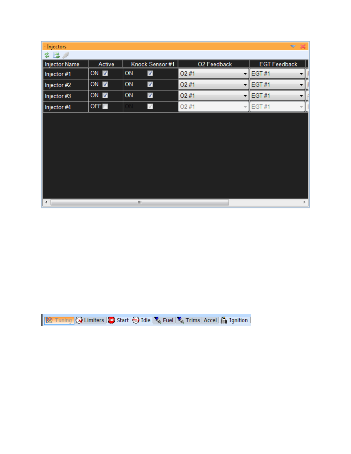
Injectors Display
Auto Arrange Displays – Automatically organizes the displays within the current tab so that
none are overlapping.
Restore Displays – Restores the workspace settings back to the previously saved settings.
TABS
AEM Tuner Tabs
The Tabs menu item lists all currently saved tabs screen templates. Right clicking in the tab
area of the menu space shown above will bring up the following menu:
Page 47 of 279 EMS-4 Install and Tuning Guide_Rev 1.6
Page 48

Tabs Menu
New tabs can be created. Existing tabs can be renamed hidden or deleted. Currently hidden
tabs can be displayed for re-use and all tab properties can be modified by selecting the Property
item.
Tabs Menu Detail
Tabs are saved as part of the Workspace configuration. Remember to save the workspace to
retain your changes.
Page 48 of 279 EMS-4 Install and Tuning Guide_Rev 1.6
Page 49

ECU
EMS Menu
Connect to ECU – Instructs AEM Tuner to attempt a communications connection with the EMS
hardware.
Disconnect – If connected, instructs AEM Tuner to close the communications connection with
the EMS.
Upload Calibration – Loads a new calibration file into the EMS.
Page 49 of 279 EMS-4 Install and Tuning Guide_Rev 1.6
Page 50

Upload Calibration Dialog
Click the Browse button to select a calibration file. Note that the calibration firmware version
must match the EMS firmware version. The current EMS version is displayed at the top of this
window. An optional check box labeled Download EMS‟s Calibration First allows the currently
loaded calibration file to be saved prior to loading the new one. When the desired calibration file
is chosen, click on the Go button to load it into the EMS. Follow the on-screen instructions and
cycle power afterwards.
Set Password – Allows the user to define a password for the EMS calibration. Must be
connected to an EMS for this function to become available.
Page 50 of 279 EMS-4 Install and Tuning Guide_Rev 1.6
Page 51

Set Password Dialog
Clear EMS Calibration – Clears the currently loaded calibration from EMS memory.
Upload EMS Firmware – Allows the user to update the EMS firmware to the most current
revision. Follow the on-screen instructions to complete the upgrade. Note that a new
calibration compatible with the new firmware version is required to complete the process.
Clear EMS Firmware – Clears the currently loaded firmware version. Follow the on-screen
instructions to complete the process.
EMS Connection Preference – Allows the user to choose how AEM Tuner will connect with the
EMS. Note that EMS-4 systems do not have a serial port connection capability.
Page 51 of 279 EMS-4 Install and Tuning Guide_Rev 1.6
Page 52

EMS Connection Preference Dialog
LOGGING
Logging Menu
Start PC Logging – (F6 Hotkey) will log data from all channel displays in the active tab.
Cancel PC Logging – (F8 Hotkey) will stop logging and discard the file.
Stop and Save – (F7 Hotkey) will stop logging and prompt the user to save the logged file.
EMS Internal Logging Setup – Opens a dialog window that allows the user to configure the
internal logging settings of the EMS.
Page 52 of 279 EMS-4 Install and Tuning Guide_Rev 1.6
Page 53

EMS Internal Logging Setup Dialog
Logging Conditions
Logging Conditions – Defines the activation criteria for the internal logging function.
Logging is Off – Internal logging function is disabled.
Logging is Always On – When the EMS is powered up, the logger is logging.
Page 53 of 279 EMS-4 Install and Tuning Guide_Rev 1.6
Page 54

Logging is on when engine is running – When engine speed is greater than 0, data will be
logged.
Logging is on when the vehicle is moving – When the vehicle speed is greater than 0, data will
be logged. Note that this setting requires a properly configured vehicle speed sensor.
Logging is on at full throttle – Data will be logged at wide open throttle only.
Logging is on with custom conditions – Logging activation is determined by the following
settings:
Logging Custom Conditions
Log Switch Settings
Select Use Switched Input to define a log activation switch input from the drop down list.
Page 54 of 279 EMS-4 Install and Tuning Guide_Rev 1.6
Page 55

Internal Logging Memory Control
Select Loop Logging to continue logging after all memory is used. Only the oldest data will be
lost when the log loops.
Use the slider to select the logging rate. The rate, channels selected and EMS logging memory
capacity will be used to estimate the log run time.
Download EMS Log Menu Item
Download EMS Log – Select this item when connected to the EMS to download the current
logged data file.
Open AEMLog – Select this item to Open AEMLog data analysis software.
Page 55 of 279 EMS-4 Install and Tuning Guide_Rev 1.6
Page 56

TOOLS
Tools Menu
Configure Output Dialog – Used to define the activation criteria for EMS configurable outputs.
Configure Outputs Dialog
Page 56 of 279 EMS-4 Install and Tuning Guide_Rev 1.6
Page 57

GPIO General Purpose Activation
To activate an output for a General Purpose Function, double click on the output function
row/column cell adjacent to the output name as shown. Select General Purpose from the drop
down list then hit the ENTER key to confirm.
Output Activation Criteria
Under Pin Configuration, check the Enable Pin box to activate the output. The Switch Input
drop down selection allows the user to select a switch input to manually activate the output.
Note that the general pin conditions must also be met in addition to the switch input status for
Page 57 of 279 EMS-4 Install and Tuning Guide_Rev 1.6
Page 58

the output to activate. To control the output using only the pin conditions, select Ignore Switch
Input and set the activation conditions as needed. In the example above the following
conditions must be true for the output to turn on:
RPM greater than 0
Engine Load greater than -14.40 psig
Throttle Position greater than 0%
Road Speed (Vehicle Speed) greater than 0
Coolant Temperature greater than -198 deg F
Configure Telemetry Dialog – Allows the user to select custom settings for serial or CAN
telemetry output. Note that the EMS-4 systems do not support serial comms or telemetry.
EMS-4 systems communicate with the PC using USB only.
Telemetry Setup Menu Items
Calibration Compare Tool – Will compare two calibrations and allow the user to copy settings
from one to the other.
Compare With Calibration Menu Item
The calibration compare tool will compare the currently loaded calibration with a second one
chosen by the user. With a calibration opened in AEM Tuner, the first step is to select the
second calibration.
Page 58 of 279 EMS-4 Install and Tuning Guide_Rev 1.6
Page 59

Compare - Open File Window
Calibration Compare Dialog
The tool will allow the user to choose and copy selected options, tables or maps values from the
“Compared Calibration” to the currently opened calibration.
Compare Calibration Detail
Page 59 of 279 EMS-4 Install and Tuning Guide_Rev 1.6
Page 60

The tabs at the top of the window allow the user to select between different types of data,
options, tables or maps.
To copy a value, highlight it and click Copy Selection. Alternatively, all items can be copied at
once by clicking the Copy All button.
Convert Current Calibration Tool – Will convert a calibration created in one EMS version to
another EMS version. Calibration versions must match the version of software installed in the
EMS. Software installed in the EMS is also referred to as firmware. The EMS firmware is
constantly being upgraded and improved. When AEM releases a new version of firmware, the
convert calibration tool allows customers to convert a previously tuned calibration so it is
compatible with the new firmware revision.
Convert Calibration Menu Item
Page 60 of 279 EMS-4 Install and Tuning Guide_Rev 1.6
Page 61

Configure Conversion Dialog
The first step is to choose the EMS version to convert the current opened calibration into. There
are two different types of conversions, Auto and Manual. Manual conversions are usually for
internal AEM use but these can also be accomplished by experienced users as well. Auto
conversions employ a conversion script provided with the new firmware release. The
conversion script simplifies the process limiting the number of decisions the user must make
during the conversion process.
Preferences – The preferences tool is used to define many AEM Tuner application specific
preferences.
Page 61 of 279 EMS-4 Install and Tuning Guide_Rev 1.6
Page 62

Tools - Preferences Menu Item
Unit Preferences
The first preference category allows the user to select their preferred units. This selection
defines what units will be used in channel displays and logged data for each type.
Unit Preferences Detail
The right hand column in this dialog includes drop down selection lists. Left click to activate the
drop down then select from the list.
Page 62 of 279 EMS-4 Install and Tuning Guide_Rev 1.6
Page 63

Display Preferences
The display preferences dialog includes basic color and font preferences for use in AEM Tuner.
Experiment to find what works best. This dialog also includes preferences for Live Tracing.
Live Tracing is used in maps to graphically highlight the areas of the map the EMS is accessing
at any given point in time. This is only active when the EMS is powered up and connected to
the PC.
Page 63 of 279 EMS-4 Install and Tuning Guide_Rev 1.6
Page 64

Hotkey Preferences
Hotkeys are time saving tools and are extremely useful. The Hotkeys preference dialog allows
the user to have complete control over the Hotkeys defined for almost any action. Many
standard Hotkeys are pre-defined. All can be modified by the user. To add a new Hotkey to
one of the action items in the list or to modify an existing Hotkey, highlight the action item then
type the preferred Hotkey into the box below:
Hotkey Detail
To define a Hotkey using the Control + I combination, click inside the Hotkey box and type
Control + I then click the Modify button to activate the change.
Page 64 of 279 EMS-4 Install and Tuning Guide_Rev 1.6
Page 65

Logging Preferences
There are two types of logging, Internal Logging and PC Logging. The system can be
configured to always log to the PC when the PC is connected to the EMS by selecting the first
checkbox in the window above. The second checkbox allows the user to always delete the log
file saved internally to the EMS after downloading. Otherwise, a copy is downloaded and the
original is retained in EMS memory. Standard log file names for both types of logging can also
be configured in this window.
Page 65 of 279 EMS-4 Install and Tuning Guide_Rev 1.6
Page 66

Calibration Edit Preferences
When the first checkbox in the window above is selected, the ENTER key must always be
pressed to confirm calibrations changes. This is the default configuration.
The Auto-Rescale selection allows AEM Tuner to continuously optimize the resolution in the
main fuel map and crank injector time table. Default setting for this selection is ON.
Page 66 of 279 EMS-4 Install and Tuning Guide_Rev 1.6
Page 67

Quick Tune Preferences
The quick tune feature allows AEM Tuner to automatically calculate main fuel map changes
necessary to minimize the O2 correction value.
Page 67 of 279 EMS-4 Install and Tuning Guide_Rev 1.6
Page 68

Application Preferences
The application preferences dialog controls settings related to Workspace, Calibration Files and
Tabs loading. It also allows the user to enable or disable the application updates feature.
When the Check for Application Updates at Startup is selected, AEM Tuner will connect to the
internet and notify the user of software or calibration file updates from AEM.
Page 68 of 279 EMS-4 Install and Tuning Guide_Rev 1.6
Page 69

WIZARDS
Wizards Menu Item
Setup Wizard – Contains pre-defined options, tables and maps to configure a calibration file for
a certain purpose. Applying a Setup Wizard modifies the currently opened calibration file.
Setup Wizards can be used to apply the proper battery offsets for fuel injectors or select the
proper settings for a certain manifold pressure, air temperature or coolant temperature sensor.
AEM is constantly adding to the list of available Setup Wizards for each EMS type.
Page 69 of 279 EMS-4 Install and Tuning Guide_Rev 1.6
Page 70

Setup Wizards
To use a Setup Wizard, select a Wizard type then either double click on the desired settings or
click once and hit the Apply button.
In addition to the generic Setup Wizard shown above, there are several specific Wizards used to
accomplish certain tasks.
Set Throttle Range Wizard – The useable range for the TPS sensor must be defined in the
calibration file accurately. The Set Throttle Range Wizard automates this process.
Set Throttle Range Wizard
The PC must be connected to the EMS. With the throttle in the full closed position, monitor the
TPS Volts value in the window above. Minimum TPS voltage is usually 0.5 – 1.0 volts. Click
the Set TPS Volts Min button. Next push the throttle to the wide open position. Monitor the
TPS Volts value. Maximum TPS voltage is usually 4.0 to 4.5 volts. With the throttle held open,
Push the Set TPS Volts Max button. Close the window. The throttle is now calibrated.
Page 70 of 279 EMS-4 Install and Tuning Guide_Rev 1.6
Page 71

Ignition Timing Sync Wizard – The purpose of the Timing Sync Wizard is to synchronize the
actual ignition timing with the value commanded by the EMS.
Ignition Timing Sync Wizard
The PC must be connected to the EMS and the engine must be running. To minimize ignition
timing fluctuation, the timing from the EMS can be locked at a given setting. Select or type in a
value then click the Lock Ignition Timing at checkbox. Next measure the ignition timing at the
balancer with a timing light and compare the actual reading to the commanded “locked” value.
If they differ, use the Advance or Retard Timing buttons to adjust the actual value until it
matches the locked timing value.
Change Injector/Pressure Wizard – If the fuel pressure setpoint is adjusted or if different size
injectors are installed on an engine that was previously tuned, the injector/pressure wizard can
be used to automatically compensate for this change.
Page 71 of 279 EMS-4 Install and Tuning Guide_Rev 1.6
Page 72

Change Injector/Pressure Wizard
Enter the original (old) injector size and pressure setting and the new settings. AEM Tuner will
automatically adjust the calibration to account for these changes.
Configure Gear Ratio Wizard – The gear ratio can be calculated based on a ratio of engine
speed to vehicle speed. Once the gear ratio is calculated, the data can be used to define a gear
position table based on calculated gear ratio. This wizard automates the process.
Page 72 of 279 EMS-4 Install and Tuning Guide_Rev 1.6
Page 73

Configure Gear Ratio Wizard
The EMS must be powered up and the PC must be connected. WARNING! This procedure
should be completed on a chassis dynamometer to ensure safety. The driven wheels must be
rotating to generate a suitable vehicle speed signal. Follow the on-screen instructions. Select
Engine Speed for GearCal Spd 1 and Vehicle Speed for GearCal Spd 2. Note that certain plug
and play applications may have different settings but these will be pre-configured in the base
calibration. While driving in each gear, click the Gear 1 – 7 buttons to sample data. When all
gears are sampled, click the Set to Gear Ratio Table button to finalize the process.
Staged Injection Wizard – This wizard is used to determine the flow ratio between the primary
and secondary injectors and to account for differences in fuel type, fuel pressure or number of
injectors.
Page 73 of 279 EMS-4 Install and Tuning Guide_Rev 1.6
Page 74

To use the wizard, enter the number of primary and secondary injectors, the flow rate of each
(as measured in the same units) and the stoichiometric ratio of the fuel used for each. Click the
OK button to complete the process.
Note that there are still certain settings necessary to completely define a staged injection
setup. These will be covered later in this manual.
LIVE TRACING
Live Tracing Menu
Page 74 of 279 EMS-4 Install and Tuning Guide_Rev 1.6
Page 75

Main Fuel Map showing Live Tracing
Live Trace
The Live Trace features displays a brief “history” of where the EMS has been accessing tuning
data from a map.
Stop Live Tracing – Stops Live Tracing if currently running.
Clear Live Tracing – Clears the current Live Trace saved in Memory.
Show Live Tracing – Displays the currently saved Live Trace.
Toggle Live Tracing Mode – Toggles between the two available Live Tracing modes, auto
fading with trail length or no fading. See also Tools – Preferences – Display.
HELP
Help Menu
Tuning Explanation – Toggles On/Off the Item Explanation pane on the right hand side of the
AEM Tuner window.
Page 75 of 279 EMS-4 Install and Tuning Guide_Rev 1.6
Page 76

Program Guide – Opens the on-line help file.
Check Updates – If connected to the internet, AEM Tuner will contact the AEM servers and
download any available software or calibration file updates.
AEM Tuner Updates Feature
Click the Download and Install button to save the files. Calibration file updates are automatically
saved in the AEM Updates folder as shown below:
Page 76 of 279 EMS-4 Install and Tuning Guide_Rev 1.6
Page 77

About AEM Tuner – Displays the installed version and build date:
Editing EMS Calibration Files
Editing Options Displays
Options can be any of the following:
1. Single numeric values like Fuel Pump Prime time in seconds
2. On/Off selections to enable or disable calibration features
3. Drop down list selections to assign an input pin or output pin for use in a calibration
feature or function.
Options Display Toolbar Icon Function
Show or hide the icon toolbar
Quick insert new option
Page 77 of 279 EMS-4 Install and Tuning Guide_Rev 1.6
Page 78

Available Options
Selected Options
Choose new option from drop down list. Option will be inserted after highlighted row.
Move selected option row up or down within the display window.
Removes currently selected option from display.
Change display contents. Opens separate window below:
Page 78 of 279 EMS-4 Install and Tuning Guide_Rev 1.6
Page 79

Select options from the left side then click OK to add them to the display. Options can also be
selected from a “Tree” type view by clicking on the Tree tab above.
Reset selected modification states. For any currently highlighted option row, clicking this
button will reset the state of the selected option.
Reset all states. Resets all modification states within the option window.
Page 79 of 279 EMS-4 Install and Tuning Guide_Rev 1.6
Page 80

Options Display – Right Click Menu
Right clicking within an option display brings up the menu above. Functions are similar to those
described above using the toolbar icons.
Editing Options Display Data
To edit a value within the options display window, first double click on the value until it is
highlighted blue as shown above. At this point, function is similar to any standard Windows text
box. Edit the value and hit the ENTER key to confirm. Double clicking on some options will
open a drop down listing. Note that the ENTER confirmation requirement is a user preference.
See Tools – Preferences – Edit for more information.
Changed option values will display a notification around the name
indicating the calibration value has changed. This option is in a “modified” state.
Page 80 of 279 EMS-4 Install and Tuning Guide_Rev 1.6
Page 81

Editing 2D Table Displays
A 2D table represents a function that equates one value to another. AEM EMS calibrations
contain many 2D tables. Examples include sensor calibration tables that equate voltage to
temperature, tables that define desired idle speed as a function of coolant temperature, etc.
2D table in Graph View mode
2D table in Table View mode
Table Display Toolbar Icon Function
Show or hide the icon toolbar
Close display
Reset all states. Resets all modification states within the table window.
Page 81 of 279 EMS-4 Install and Tuning Guide_Rev 1.6
Page 82

Reset selected modification states. For any currently highlighted cell, clicking this button
Left click and
manually
will reset the modification state of the selected cell.
Toggles table view mode
Toggles graph view mode
Toggles split graph/table mode
Auto table sizing. Allows table cells and data to expand to fit current window size.
Font table sizing. Maintains table font size specified in Tools – Preferences – Display –
Font.
Follow ECU. Selected cell or cell group will follow the table cursor while live tuning.
Manual selection. Selected cells are independent of live cursor position.
Manual Table Editing with +/- keys
drag to select
data in either
view.
Use +/- keys to
add or subtract
Page 82 of 279 EMS-4 Install and Tuning Guide_Rev 1.6
Page 83

To modify table data, left click and drag to select the cells you want to change. Add or subtract
from the existing value using the + and – keys. Holding the CNTRL key down will create larger
changes.
Table Editing with Right Click Menu
Percent Change – (hotkey E) applies a
percentage offset to the value(s). Note that
the percentage calculation type is a user
preference.
Set Value – Replaces the existing value(s)
with the new one entered.
Add Value – Adds an offset to the existing
value(s)
Interpolate Horizontally - Uses the first and
last cells selected in the direction of
Page 83 of 279 EMS-4 Install and Tuning Guide_Rev 1.6
Page 84

interpolation (either horizontal or vertical) to determine a linear slope, then changes the values
of all the cells in between so they have the same slope.
Before Interpolation:
Highlighting Cells to Interpolate:
Page 84 of 279 EMS-4 Install and Tuning Guide_Rev 1.6
Page 85

After Interpolation:
Other Editing Options:
There are four other automatic editing options:
Linear Extrapolate (left or right) - Extends the slope of the first two selected cells to the rest of
the cells selected in the interpolation direction.
Flatten (left or right) - Allows the user to assign to a group of selected cells the value of the
first cell in the flatten direction.
Page 85 of 279 EMS-4 Install and Tuning Guide_Rev 1.6
Page 86
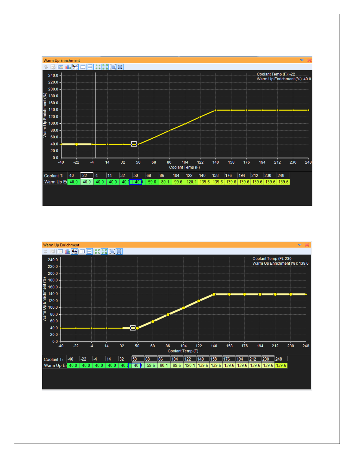
Before Linear Extrapolation:
Selecting Cell Range to Extrapolate:
Page 86 of 279 EMS-4 Install and Tuning Guide_Rev 1.6
Page 87

After Extrapolation:
Before Flattening:
Page 87 of 279 EMS-4 Install and Tuning Guide_Rev 1.6
Page 88

Selecting Cells to Flatten:
After Flattening Right:
Page 88 of 279 EMS-4 Install and Tuning Guide_Rev 1.6
Page 89

Editing Channel Displays
Channel Display Toolbar Icon Function
Show or hide the icon toolbar
Quick insert new channel
Move selected channel row up or down within the display
window.
Removes currently selected channel from display.
Change display contents. Opens separate window below:
Add or subtract channels by selecting them in left column. Click OK to confirm. Tree view is
also available by clicking the Tree tab.
Configure channel properties. Allows changes to how data is presented in the channel
displays.
Page 89 of 279 EMS-4 Install and Tuning Guide_Rev 1.6
Page 90

Select the desired channel then click the column next to each property to edit the settings.
Decimal Places – Specifies how many digits after the decimal point
Display Name – Alternative user defined name for the channel
Display Type – How to display the data – numeric value, bar graph or both
High Warning Value – Channel display will turn red when above this value
Live ECU Refresh Rate – Controls how often the channels value is refreshed from the ECU
when connected
Low Warning Value – Channel display will turn red when below this value
Maximum Value – The maximum value the channel displays
Minimum Value – The minimum value the channel displays
Editing 3D Map Displays
Table Display Toolbar Icon Function
Page 90 of 279 EMS-4 Install and Tuning Guide_Rev 1.6
Page 91

Show or hide the icon toolbar
Close display
Reset all states. Resets all modification states within the map window.
Reset selected modification states. For any currently highlighted cell, clicking this button
will reset the modification state of the selected cell.
Toggles table view mode
Toggles graph view mode
Toggles split graph/table mode
Toggles horizontal view orientation. Only available in split graph/table mode
Toggles vertical view orientation. Only available in split graph/table mode
Split graph/table mode (horizontal orientation):
Page 91 of 279 EMS-4 Install and Tuning Guide_Rev 1.6
Page 92

Split graph/table mode (vertical orientation):
Auto table sizing. Allows map cells and data to expand to fit current window size.
Font table sizing. Maintains map font size specified in Tools – Preferences – Display – Font.
Follow ECU. Selected cell or cell group will follow the map cursor while live tuning. With this
feature turned on, tune with the +/- keys live and be sure you are editing the exact location used
by the ECU.
Manual selection. Selected cells are independent of live cursor position.
Rotate, Zoom and Pan. When selected, left click and rotate to rotate the graph view. Hold
the CNTRL key while left clicking to pan the view.
Select and change. When this icon is active, left click and drag to highlight (select) areas of
the map to edit.
Page 92 of 279 EMS-4 Install and Tuning Guide_Rev 1.6
Page 93

Highlighted area selected:
User definable 3D positions. Set map to desired view orientation then right click over
each of these buttons to select up to 3 default 3D orientations.
Manual Editing with +/- Keys
Highlighted area
increased using the +
key
Note: Display color
preferences and
orientation changed to
illustrate variations
Page 93 of 279 EMS-4 Install and Tuning Guide_Rev 1.6
Page 94

Automatic Editing with Right Click Menu
Right click menu editing options
for 3D maps are similar to those
for the 2D tables but there are
more of them.
Interpolate Horizontally (H hotkey)
Interpolate Vertically (V Hotkey)
Interpolate Both (B Hotkey)
Linear Extrapolate Left
Linear Extrapolate Right
Linear Extrapolate Up
Linear Extrapolate Down
Flatten Left (Shift-A Hotkey)
Flatten Right (Shift-D Hotkey)
Flatten Up (Shift-E Hotkey)
Flatten Down (Shift-S Hotkey)
Page 94 of 279 EMS-4 Install and Tuning Guide_Rev 1.6
Page 95

Before horizontal
interpolation.
Area of interest
highlighted.
After horizontal
Interpolation.
Vertical
interpolation
results similar but
in vertical
direction.
Interpolate Both
will affect both
directions
Page 95 of 279 EMS-4 Install and Tuning Guide_Rev 1.6
Page 96

Before linear extrapolate
right. Area of interest
highlighted.
After linear extrapolate right.
Linear extrapolate left results
similar but in opposite
direction. Up and down affect
also similar.
Page 96 of 279 EMS-4 Install and Tuning Guide_Rev 1.6
Page 97

Before flatten right. Area of
interest highlighted.
After flatten right. Flatten
left, up and down results are
similar.
Page 97 of 279 EMS-4 Install and Tuning Guide_Rev 1.6
Page 98

Part 3 – Tuning Guide
Background
What is “Tuning”? Tuning can mean anything from adjusting the idle mixture screw on your
carburetor to experimenting with custom length headers for your engine to setting up the flow
ratio between primary and secondary injectors for your EFI calibration. Tuning covers a wide
range of topics and not all are related to fuel injection. For the purpose of this manual, tuning
refers to the act of making changes to a calibration file for an AEM engine management system
(EMS) to optimize the performance of an engine.
In its most basic form, EFI tuning involves optimizing the fuel flow and spark advance variables
to maximize performance and economy.
Fuel Tuning General
Concepts
The chart at left illustrates the
effect of fuel flow on engine
performance at a constant
operating set point (fixed RPM
and throttle position). This kind
of data is recorded under
laboratory engine testing
conditions. The test is started at
a very rich air/fuel ratio. The
mixture is leaned at a controlled
rate and data is recorded along
the way. The first transition
occurs when horsepower
reaches a peak and begins to fall
again (best power AFR). The
next transition is when cylinder
head temperature reaches a
peak and begins to fall. The
next item of interest is peak
exhaust gas temperature (EGT).
Shortly afterwards, the specific
fuel consumption reaches a
minimum and begins to increase
(best economy range) indicating
the engine is running at a
mixture that is so lean, it is
becoming difficult to support
combustion.
Page 98 of 279 EMS-4 Install and Tuning Guide_Rev 1.6
Page 99

Spark Tuning General Concepts
The ignition timing or spark timing value refers to the distance in crank degrees between the
spark plug firing event (initiating combustion) and the uppermost point of the pistons stroke (top
center TC, top dead center TDC, etc.)
If the start of the combustion process is progressively advanced before TC, the compression
stroke work transfer (which is from the piston to the cylinder gases) increases. If the end of the
combustion process is progressively delayed by retarding the spark timing, the peak cylinder
pressure occurs later in the expansion stroke and is reduced in magnitude. These changes
reduce the expansion stroke work transfer from the cylinder gases to the piston. The optimum
timing which gives the maximum brake torque - called maximum brake torque or MBT timing
occurs when the magnitudes of these two opposing trends just offset each other. Timing which
is advanced or retarded from this optimum gives lower torque. MBT timing defines the
optimum point (maximum brake torque) for peak cylinder pressure relative to crank angle.
Certain operating conditions, combustion chamber designs, fuel types, etc. will prohibit an
engine from reaching MBT timing before detonation occurs. Detonation, or spark knock is
caused by the combustion gases spontaneously combusting at the outer edges of the piston
before the normal combustion flame front reaches those areas. This causes pressure spikes
that can damage the engine over time.
Every engine will have different spark timing requirements. Unlike fuel tuning where you can
take advantage of inexpensive, commonly available wideband oxygen sensor kits, spark tuning
requires expensive laboratory equipment for complete optimization. Spark tuning is best
accomplished on an engine dyno. If that is not practical, a chassis dyno is the next best thing.
Even with the use of a dyno though, spark tuning requires experience to know where to start
and what kind of changes to make. Ignition timing values can range from 50+ degrees BTDC to
15+ degrees after top dead center for certain extreme conditions on race vehicles.
Page 99 of 279 EMS-4 Install and Tuning Guide_Rev 1.6
Page 100

Calibration Setup
Base Calibrations
There are several base calibrations that can be used as a starting point. They are installed with
the software and located here:
C:\Program Files\AEM\AEMTuner\Calibrations\AEM Updates\EMS4
AEM is constantly adding to, updating and improving the base calibration library. Go to the File
menu and select Calibration Notes… for information on each file. Example shown below:
Page 100 of 279 EMS-4 Install and Tuning Guide_Rev 1.6
 Loading...