

Page 1

WARNING:
!
This installation is not for the tuning novice nor the PC illiterate!
Use this system with EXTREME caution! The AEM EMS System
allows for total flexibility in engine tuning. Misuse of this
product can destroy your engine! If you are not well versed in
engine dynamics and the tuning of management systems or are
not PC literate, please do not attempt the installation. Refer the
installation to a AEM trained tuning shop or call 800-423-0046
for technical assistance. You should also visit the AEM EMS
Tech Forum at http://www.aempower.com
NOTE: AEM holds no responsibility for any engine damage that
results from the misuse of this product!
Vehicle fitment
Series I EMS
Series II EMS
2004 Subaru WRX STI
30-1820
30-6820
2005-2006 Subaru WRX STI
30-1821
30-6821
Installation Instructions for:
EMS P/N 30-6820
2004 Subaru WRX STI (USDM 2.5L turbo)
and
EMS P/N 30-6821
2005-2006 Subaru WRX STI (USDM 2.5L turbo)
This product is legal in California for racing vehicles only and should never be used
on public highways.
2011 Advanced Engine Management, Inc.
ADVANCED ENGINE MANAGEMENT INC.
2205 126th Street Unit A Hawthorne, CA. 90250
Phone: (310) 484-2322 Fax: (310) 484-0152
http://www.aemelectronics.com
Instruction Part Number: 10-6820
Page 1 of 21
Page 2

Thank you for purchasing an AEM Engine Management System.
The AEM Engine Management System (EMS) is the result of extensive development on a
wide variety of cars. Each system is engineered for each particular application. The AEM
EMS differs from all others in several ways. The EMS is a stand alone system, which
completely replaces the factory ECU and features unique Plug and Play Technology, which
means that each system is configured especially for your make and model of car without any
jumper harnesses. There is no need to modify your factory wiring harness and in most cases
your car may be returned to stock in a matter of minutes.
For stock and slightly modified vehicles, the supplied startup calibrations are configured to
work with OEM sensors, providing a solid starting point for beginner tuning. For more heavily
modified cars, the EMS can be reconfigured to utilize aftermarket sensors and has many
spare inputs and outputs allowing the elimination of add-on rev-limiters, boost controllers,
nitrous controllers, fuel computers, etc. It also includes a configurable onboard 1MB data
logger that can record any 16 EMS parameters at up to 250 samples per second. Every
EMS comes with all functions installed and activated; there is no need to purchase options or
upgrades to unlock the full potential of your unit.
The installation of the AEM EMS on the supported vehicles uses the stock sensors and
actuators. After installing the AEMTuner software, the startup calibration will be saved to the
following folder on your PC:
C:\Program Files\AEM\AEMTuner\Calibrations\AEM Updates\Subaru\
Multiple calibrations may be supplied for each EMS; additional details of the test vehicle
used to generate each calibration can be found in the Calibration Notes section for that file.
Please visit the AEM Performance Electronics Forum at http://www.aemelectronics.com and
register. We always post the most current strategy release, PC Software and startup
calibrations online. On the forum, you can find and share many helpful hints/tips to make
your EMS perform its best.
TUNING NOTES AND WARNING:
While the supplied startup calibration may be a good starting point and can save
considerable time and money, it will not replace the need to tune the EMS for your specific
application. AEM startup calibrations are not intended to be driven aggressively before
tuning. We strongly recommend that every EMS be tuned by someone who is already
familiar with the AEM software and has successfully tuned vehicles using an AEM EMS.
Most people make mistakes as part of the learning process; be warned that using your
vehicle as a learning platform can damage your engine, your vehicle, and your EMS.
Page 2 of 21
Page 3

Read and understand these instructions BEFORE attempting to install this product.
Subaru 2004 / 2005-2006 Model Year Differences
Although there are very few differences between the 2004 and 2005-2006 models, the ECUs
are not interchangeable. The 30-1820 EMS must be used in a 2004 vehicle, and the 30-1821
EMS must be used in 2005-2006 vehicles. Consult the pinout chart for further information.
Peak and Hold Injector Drivers
Injectors 1-4 include Peak (4 amps) and Hold (1 amp) injector drivers. These drivers may be
used with peak and hold or saturated type injectors. The vehicle’s wiring harness may
contain a resistor pack to prevent excessive current if low-impedance injectors were used
with the stock ECU. With the 30-6820 installed, users can elect to remove and bypass
injector resistors for more precise control of low-impedance injectors.
Please note that the injector response time will be different with and without injector resistors
installed. If a resistor pack has been removed and bypassed, please use the correct battery
offset wizard for your injectors. Most battery offset wizards will specify <P&H DRIVER> if
they are intended for use without a resistor pack.
Fuel Pump Control
As supplied from Subaru, the OEM ECU interfaces with a fuel pump control unit (FPCU) to
control the speed, high or low, of the fuel pump based on load. The AEM EMS has the ability
to replicate this functionality; however it is configured in the Startup Calibration to run the fuel
pump at high speed at all times.
The EMS Output COIL8 (Pin B26 for 2004 models, pin B27 for 2005-2006 models) is used to
send a 5V signal instructing the OEM fuel pump ECU to energize the fuel pump. Configuring
User PW Out to use LS12 and, for example, User PW Analog In to MAP Volts will allow the
voltage sent to the fuel pump ECU to be varied in relation to MAP Volts/pressure. Increasing
the duty cycle of the LS12 output will decrease the speed of the fuel pump.
WARNING: Reducing the voltage sent to the fuel pump can affect fuel pump output (volume
and/or pressure). If you wish to decrease pump speed at light loads or low RPM, monitor
fuel pressure and air-fuel ratio very carefully to avoid engine damage!
WARNING: Do not use pin B26/B27 to control a fuel pump relay directly, it must be
connected to the OEM fuel pump control unit only. If an aftermarket fuel pump relay will be
installed, wire it to be controlled using a spare low side output (for instance, LS2 is available
on pin A13). Be sure to configure the output to use the Fuel Pump function using
Tools>>Configure Outputs.
Page 3 of 21
Page 4
Variable Valve Control (VVC)
The Variable Valve Control table in the EMS can be used to control the STI’s AVCS system,
which is used to change the airflow characteristics of the engine by advancing the timing of
the intake camshafts. The AVCS outputs (pin A28-A29, Injector 9-10 outputs on the EMS)
advance the phase angle of the intake camshafts; this will have effects similar to moving an
adjustable intake cam gear. This is controlled by the VVC 1 (RH camshaft) and VVC 1B (LH
camshaft) outputs; VVC position is monitored using the T2 and T3 inputs for independent
closed-loop feedback. The VVC settings can be adjusted in the VVC tab (which may be
hidden in the default AEM workspace).
This system is active on this EMS when used with the provided startup calibrations and can
be adjusted through the use of the ‘VVC 1 Target’ map. Adjustments to the intake cam timing
are made by changing the values in the ‘VVC 1 Target’ map per Engine RPM and Engine
Load. The values in the ‘VVC 1 Target’ map can vary from 0 degrees for zero intake cam
advance to 50 degrees for full intake cam advance. The channels ‘VVC 1 Advance’ and
‘VVC 1B Advance’ show the measured position of the camshafts.
WARNING: Improper use of the Variable Valve Control (VVC) in the AEMTuner software can
lead to engine damage!
Be very careful when building or tuning unknown engine combinations or using aftermarket
pistons or valve train components. OEM engines and valve trains are not designed or
manufactured to allow valve to piston interference at certain cam angles. AEM will not be
responsible for engine damage resulting from improper use of the VVC function on engines
with valve trains designed to allow mechanical interference.
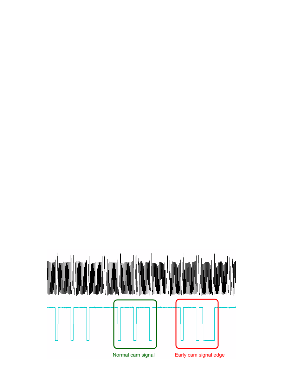
Please note that some Subaru camshaft sensors will send ‘false signals’ under some
conditions (often light load and low RPM). This can be observed with an oscilloscope or
high-speed datalogger, and occurs with the stock ECU as well. These false signals will not
cause engine misfires with the Series 2 EMS, but will sometimes be reflected as quick jumps
in the measured ‘VVC 1 Advance’ channels.
Page 4 of 21
Page 5

EMS DC Stepper Motor control (Subaru Tumble Generator Valves)
There are two sets of Tumble Generator Valves (TGV) found on the intake manifold of the
STI. Each set of valves is driven by a DC stepper motor and has a 0-5V feedback signal to
monitor valve position. The Motor 1 and Motor 2 Target tables are used to set the position of
the valves; valve position can be controlled based on various parameters such as throttle
position, vehicle speed, engine RPM, or engine load. The channels “ADCR11” and
“ADCR14” display the current position of the valves. When these parameters are near 0
Volts, the valves are open and will allow maximum air flow. When these parameters are near
5 Volts, the valves are closed creating turbulence in the intake stream and restricting air flow.
The valves are always open in the AEM-supplied startup calibrations.
WARNING: the EMS can be configured to control the left and right bank independently. The
engine will run very poorly if one set of TGVs is fully open while the other set is fully closed,
so please be sure that the Motor 1 and Motor 2 Target tables are both the same.
Subaru MAF sensor, Intake Air Temp sensor
The MAF (mass air flow) sensor can be removed to help decrease intake air restriction as
the base map uses the factory MAP sensor to determine engine load. Please be aware that
the IAT (intake air temperature) sensor is integrated into the factory MAF sensor. If the
factory MAF / IAT sensor is removed, you may wish to install an AEM IAT Sensor Kit (P/N
30-2010), which includes a sensor, wire connector, and aluminum weld-in bung. While the
factory MAF sensor locates the IAT sensor upstream of the turbocharger inlet, it may be
preferable to install an IAT sensor downstream of the intercooler to accurately measure
charge temperatures.
EMS Fuel Map, Boost Fuel Trim Table
The 30-6820 calibration maps provided utilize the “Boost Fuel Trim Table” to provide a 1:1
fuel compensation above and below atmospheric pressure. To use this table, the “Boost Fuel
Trim Table” should be configured to provide twice as much fuel when the manifold pressure
is twice as high and half the fuel when the manifold pressure is half as high; this should help
simplify the tuning process for different vacuum and boost levels. Notice the values in the
main “Fuel Map” do not change significantly above 100 kPa (0 psi boost), the fuel correction
is being made by the “Boost Fuel Trim Table.”
Note: the “Boost Fuel Trim Table” must be adjusted if a different MAP sensor is installed or if
the Load breakpoints are adjusted. The Boost Fuel Trim value should be set to -90 at 10kPa,
0 at 100 kPa, +100 at 200 kPa, +200 at 300 kPa, etc…
Check Engine Light
The Low Side 10 output (LS10) activates the Check Engine Light on the gauge cluster. It is
configured to activate at low RPM in the AEM startup calibrations; this can be reconfigured
by selecting Tools>>Configure Outputs.
Page 5 of 21
Page 6
AEM Electronic Throttle Control System (ETC)
Figure 1 - Minimum Pedal to Bracket Clearance
The 30-6820 EMS incorporates an ETC system which controls the OEM electronic throttle body. All
components of this system, unmodified and as delivered from the manufacturer, are required for optimum and
safe functionality of this system. These components include, but are not limited to, wiring, ETC relay,
accelerator pedal assembly, and throttle body.
The EMS ETC control system incorporates multiple failsafe strategies such that in the event of a component
failure, the system will shut down the ETC system and, if necessary, the engine in a graceful manner. It still
remains the user’s responsibility to ensure that all vehicle, component, and wiring systems are maintained to a
level of workmanship consistent with industry standards.
Note: As the EMS is intended for use on vehicles that are to be operated off-road only, the factory cruise
control system will be non-operational after installation of the EMS.
Installation Information
The 30-6820 AEM EMS was designed to work with the vehicle, its components, and wiring as delivered from
the manufacturer. If any of the components or wiring have been changed or if the drive-line from the original
vehicle has been placed in another vehicle such in a custom race application then the user should take heed of
the following notes.
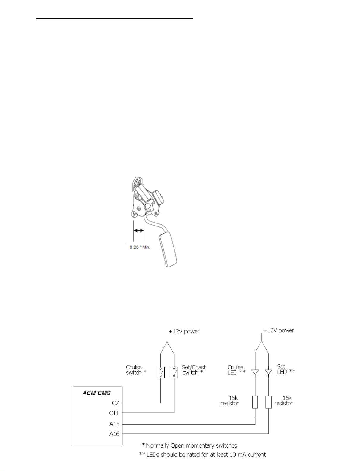
A mechanical Wide Open Throttle/”WOT” accelerator pedal travel stop is installed in the floor and/or carpet of
the vehicle as delivered from the manufacturer. If this stop is removed for any reason, such as removing the
carpet for use in a race vehicle, the user must ensure that a stop of some sort is fabricated and installed. This
stop must be fabricated such that there is a minimum clearance of 0.250 inches between the accelerator pedal
mounting bracket and the accelerator pedal actuating rod when the pedal is at WOT. See Figure 1.
The CRUISE and SET/COAST buttons, and the CRUISE and SET dashboard indicator lights are an integral
part of the ETC system calibration and diagnostic functions. It is, therefore, not recommended that these
buttons and lights be completely removed from the vehicle such as could be the case with a purpose-built race
vehicle. If the OEM steering wheel and/or gauge cluster have been removed, please temporarily re-install them
to calibrate the ETC unit, or add switches and lights to the vehicle as shown:
Page 6 of 21
Page 7
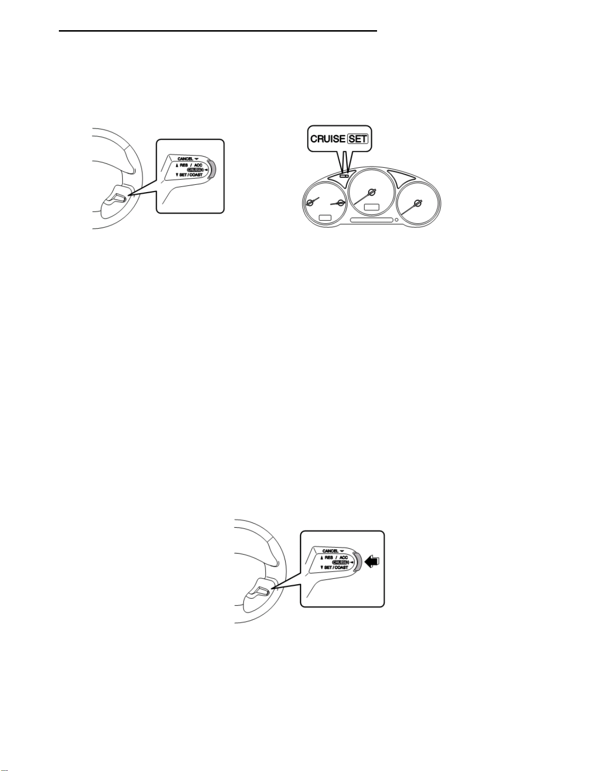
Electronic Throttle Control System Calibration Procedure
Figure 2 - “CRUISE” and “SET/COAST” buttons
Figure 3 -“CRUISE” and “SET” indicator lights
Figure 4 – Pressing the “CRUISE” button
The 30-6820 / 30-6821 EMS, as delivered, requires a specific calibration procedure to be performed prior to
use. Before beginning this procedure, please be familiar with the location and function of the CRUISE and
SET/COAST buttons on the Cruise Control Steering Column Stalk as depicted in Figure 2. Also be aware of
the (green) CRUISE and SET indicator lights on the dashboard, Figure 3. This procedure should be
repeated any time any part of the ETC system has been serviced, removed, or replaced.
Note: Do not attempt to start or run the engine during the calibration procedure. The EMS will disable engine
start/running whilst in calibration mode.
1. Initial Calibration Procedure
a. Turn the ignition key to the ON position. The CRUISE and SET indicator lights will begin flashing in
unison at a medium rate.
b. Press and hold the CRUISE button (See Figure 4) for approximately three (3) seconds until the
indicator lights stop flashing.
c. There will be a brief delay after which the CRUISE light will flash once.
d. Ensure the accelerator pedal is not being depressed and is in the full “UP” position.
e. The SET indicator light will flash rapidly for a few seconds as the EMS calibrates this position.
f. There will be a brief delay after which the CRUISE light will flash twice.
g. Depress and hold the accelerator pedal to the floor and ensure it is in the full Wide Open
Throttle/“WOT” position.
h. The SET indicator light will flash rapidly for a few seconds as the EMS calibrates this position.
i. There will be a brief delay after which the CRUISE light will flash three times.
j. The SET indicator light will flash rapidly for several seconds as the EMS calibrates the ETC throttle
body.
k. If the calibration procedure was successful and all the ETC sensors and actuators are found to be
within tolerance then the CRUISE and SET indicator lights will flash in unison at a medium rate.
l. If the calibration procedure fails, indicated by the CRUISE and SET indicator lights flashing in an
alternating pattern, please reference the sections entitled ETC Diagnostics and Calibration
Troubleshooting elsewhere in this document.
m. Turn the ignition key to the OFF position.
n. The ETC system is now calibrated and ready for use.
Page 7 of 21
Page 8

Figure 5 - Pressing the “SET/COAST” and “CRUISE” buttons
2. EMS Calibration
a. Connect to the EMS using AEMTuner.
b. Edit the Idle% vs. Target table, such that all cells are set to zero (0) percent.
c. Edit A/C Idle Load Comp and/or Idle Extra <12 Volt Options, to zero (0) percent.
d. Verify that the EMS parameter Idle Position parameter is zero (0) percent.
e. Select Wizards >> Set Throttle Range Wizard in the AEMTuner software and complete the procedure.
f. Restore the above Options to their original values to ensure proper idle control functionality.
Re-calibrating the Electronic Throttle Control System (ETC) Calibration
Once the ETC system calibration procedure has been performed, it should not need to be re-calibrated unless
one or more of the following is true:
The APP sensor, TPS, or throttle body have been removed, replaced, or adjusted.
The EMS has been removed and installed in a different vehicle.
AEM Technical Support has requested it to be performed.
The following procedure describes the steps to re-activate calibration mode on a system that has already been
calibrated.
Activate Calibration Mode
a. Ensure the ignition key is in the OFF position.
b. Press and HOLD both the CRUISE and SET/COAST buttons. Please note that the CRUISE button is
activated by pressing the end of the Cruise Control Steering Column Stalk and the SET/COAST button
is activated by pulling the entire stalk downward as depicted in Figure 5. Both buttons must be
depressed and held prior to moving on to the next step.
c. Turn the ignition key to the ON position.
d. Keep holding both the CRUISE and SET/COAST buttons for approximately ten (10) seconds until the
CRUISE and SET indicator lights (Figure 3) begin flashing in unison at a medium rate.
e. Release the CRUISE and SET/COAST buttons.
f. Calibration mode has now been activated. Follow the steps in Electronic Throttle Control System
Calibration Procedure – Initial Calibration Procedure to complete the process.
Page 8 of 21
Page 9

EMS Idle Control Calibration
Figure 9 - CRUISE and SET Indicator Lights as diagnostic outputs
The ETC idle control can be configured and calibrated via the AEMTuner software similarly to more traditional
systems that use an idle air bypass valve. There are a few calibration options that are set specifically to allow
proper ETC idle control and must not be changed from the values set forth in the 30-1820 startup calibration.
The options listed below must remain set as depicted for predictable ETC idle control. The other options that
are not highlighted have been set up for stable idle control in the 30-6820 startup calibration but are, however,
available for adjustment as the calibrator sees fit.
Idle On if TP Less = 13%
Idle Off if TP Over = 13%
Idle Invert = ON
Idle FB Dir Invert = ON
Idle PW Frequency = 10000.0 uS
ETC Fault Management
The ETC system continuously monitors itself for proper operation. If a fault is detected then the system will be
placed in a failsafe mode and power to the electronic throttle body will be turned off. This will allow the engine
to start and idle at approximately 1500-2000 rpm as a “limp-home” mode but the throttle body will not respond
to accelerator pedal inputs.
The system will continue to monitor itself and assume that the throttle blade will be in its rest position while in
this un-powered failsafe mode. If it is detected that this is not the case then the system will enter a second
failsafe stage whereby the crank signal to the EMS is interrupted. The tachometer will drop to zero and the
EMS will not fire fuel injectors or ignition coils. If the engine is running, it will coast to a stop. If the engine is not
running, it will not start.
ETC Diagnostics
The AEM EMS ETC system uses the CRUISE and SET indicator lights on the dashboard to display diagnostic
information to the user. The indicator lights flash in different ways for different purposes as described in the
following sections.
Boot-Up
When the ignition key is turned on and the EMS is powered up, both of the CRUISE and SET indicator
lights will flash briefly to signify the ETC system has booted up and that the indicator lights are
functioning properly.
Fault Detected
When the ETC system detects a fault, the CRUISE and SET indicator lights will flash in an alternating
fashion to alert the user a fault has been detected. This will happen in one of two situations:
1. Calibration Fault – A failed calibration will be detected if one of the sensors is found to be out of
the expected range during the calibration procedure. The indicator lights will flash in an
alternating pattern to alert the user of this fault for a period of approximately twenty (20)
seconds. After this time period, the CRUISE light will remain off and the SET indicator light will
flash a fault code. Please reference Table 1 for a description of the fault codes. The system
will flash the code repeatedly until the ignition is turned off.
Page 9 of 21
Page 10

Sensor
Mechanical Position
Voltage Limit (VDC)
APP1 ( Main )
Minimum ( Idle )
1.00 ± 0.35
Maximum ( WOT )
4.00 ± 0.45
APP2 ( Sub )
Minimum ( Idle )
1.00 ± 0.35
Maximum ( WOT )
4.00 ± 0.45
TPS1 ( Main )
Minimum ( Idle )
0.70 ± 0.30
Maximum ( WOT )
4.10 ± 0.45
TPS2 ( Sub )
Minimum ( Idle )
1.45 ± 0.30
Maximum ( WOT )
4.10 ± 0.45
Table 4 – Sensor Electrical Calibration Limits
Calibration Faults
1
APP Minimum
2
APP Maximum
3
TPS Minimum
4
TPS Maximum
5
RP / Relay
Table 1 – System Fault Code
Operational Fault – Failure Type
1
Out of Range
2
Noise
3
Disagreement
4
General
5
F2 6 N/A 7 N/A 8 N/A 9 N/A
Table 3 – Failure Type Fault Code
Operational Fault - System
1
APP
2
TPSA
3
TPSB
4
Target
5
System Voltage
6
Motor Driver
7
WDR
8
EEPROM
9
N/A
Table 2 – System Fault Code
2. Operational Fault – When the system detects a fault during normal operation (e.g. driving,
idling, etc), the indicator lights will repeatedly flash in an alternating pattern to alert the user of
this fault until the ignition key is turned off. Note that the ETC system will not be functional and
the EMS may disable engine operation during this mode depending on the severity of the fault.
Once the ignition has been turned off and then on again the indicator lights will flash the fault
code for the affected system. The affected ETC system code will be first flashed on the
CRUISE light after which the failure type will be flashed on the SET light. These codes are
listed in Table 2 and Table 3. The ETC system will remain un-activated until the following bootup cycle, i.e. key-off then key-on.
Troubleshooting Calibration Faults
A calibration fault will be reported if the Accelerator Pedal Position (APP) or Throttle Position Sensor
(TPS) sensors are found to be outside of the specification limits. Table 4 details the electrical limits for
these sensors.
A fault code of “5 - RP / Relay” may be caused by a fouled throttle bore, a malfunctioning or missing
ETC relay, or if the throttle body has mechanically failed.
Page 10 of 21
Page 11

Troubleshooting Operational Faults
Should an operational fault be detected, please read and follow the following suggestions for each
system.
APP
Ensure the accelerator pedal position sensor is in good condition and plugged in.
Double-check that APP sensor is wired per OEM specifications.
Check all wiring for shorts or intermittent connections.
TPSA/TPSB
Ensure the throttle position sensor is in good condition and plugged in.
Double-check that throttle body/TPS sensor is wired per OEM specifications.
Check all wiring for shorts or intermittent connections.
Target
Ensure throttle body bore is clean and free from obstruction.
Ensure vehicle battery is in good condition and properly charged.
System Voltage
Ensure vehicle battery is in good condition and properly charged.
Check all wiring for shorts or intermittent connections.
Motor Driver
Double-check that throttle body/TPS sensor is wired per OEM specifications.
Check throttle body wiring for shorts or intermittent connections.
Ensure EMS has not been installed in an area of extreme heat ( > 120°C)
WDR
Contact AEM EMS Technical Support
EEPROM
Perform ETC system calibration
Restore ETC system factory calibration
Contact AEM EMS Technical Support
Page 11 of 21
Page 12

+5V Sensor Power (tapped)
Sensor Ground (tapped)
MAP Signal
Sensor Ground (tapped)
O2 Sensor 1
Black (Sensor Ground)
Green (MAP Signal)
Red (+5V Sensor Power)
Black (Battery or chassis ground)
Red (+12V power, 5A fuse)
AEM UEGO
P/N: 30-5130
Brown (Analog - signal)
White (0-5V Analog + signal)
Pink (Switched +12V Power)
MAP Sensor
P/N: 30-2130-50
A5
A4, C31, or C35
A4, C31, or C35
C16
C22
IAT Sensor
Sensor Ground (tapped)
Air Temperature Sensor
P/N: 30-2010
A4, C31, C35
C13
Switch connects to GND
Ground
Switch 2 Input
C9
AEM EMS P/N:
30-6820 or 30-6821
Pin
Vehicle harness destination
30-1820 function
30-6820 function
Notes
A2
Front O2 sensor heater
Injector #5
---
Injector 5 moved to pin C2
A3
Front O2 sensor heater
Injector #6
---
Injector 6 moved to pin C1
A4
---
---
Sensor Ground
Additional spare output
A5
---
---
O2 #1
Additional spare output
B13
---
---
Coil 6
Additional spare output
B14
---
---
Coil 5
Additional spare output
B15
Ignition Control #4
Coil #5
Coil 4
Calibration must be updated
B26
Fuel Pump Control
Idle #1/2
Coil 8, LS 12
See ‘Fuel Pump Control’ on page 3
B28
---
---
CANH
B29
---
---
CANL
B34
---
---
HS1
C1
---
---
Injector 6
C2
---
---
Injector 5
C24
---
---
Knock 2
Additional spare input
D17
Main Relay control
FM
Coil 7
Use Coil7 settings in AEM startup cal
Wiring accessories to the EMS
Please follow this suggested wiring diagram when adding new accessories and retaining
original accessories such as the multiplex coolant temperature gauge, air conditioning
switch, reverse lockout, UEGO gauges, MAP sensors, IAT sensors, or switches for use with
the EMS. Note that wire polarity is not important for the Air Temperature sensor.
30-1820 (Series 1) vs 30-6820 (Series 2) EMS differences:
The EMS functions assigned to certain pins have been changed and no longer match the 301820 EMS. Unless otherwise noted, the following pins and functions will need to be manually
reconfigured after using AEMTuner to convert a 30-1820 Series1 EMS calibration for use
with the 30-6820 Series 2 hardware.
Page 12 of 21
Page 13

1) Install AEMTuner software onto your PC
The latest version of the AEMTuner software can be downloaded from the AEMTuner
section of the AEM Performance Electronics forums found at www.aemelectronics.com
Series 2 units are not supported by the older AEMPro tuning software.
2) Remove the Stock Engine Control Unit
a) Disconnect negative terminal from battery
b) Access the stock Engine Control Unit (ECU). The location of the ECU on the WRX is
underneath the passenger side floorboard. A 10mm socket is required to remove the
kick panel that covers the stock ECU.
c) Carefully disconnect the wiring harness from the ECU. Avoid excessive stress or
pulling on the wires, as this may damage the wiring harness. All connectors must be
removed without damage to work properly with the AEM ECU. Do not cut any of the
wires in the factory wiring harness to remove them.
d) Remove the fasteners securing the ECU to the car body, and set them aside. Do not
destroy or discard the original ECU, as it can be reinstalled easily for street use and
troubleshooting.
3) Install the AEM Engine Management System
a) Plug the factory wiring harness into the AEM EMS and position it so the wires are not
pulled tight or stressed in any manner. Secure the EMS with the provided Velcro
fasteners.
b) Reconnect the negative battery terminal.
c) Plug the communications cable into the EMS and into your PC.
d) Turn the ignition on, but do not attempt to start the engine.
e) At the time these instructions were written, new EMS units do not require USB drivers
to be installed on the PC. The EMS will automatically be detected as a human
interface device (HID).
f) With the AEMTuner software open, select ECU>>Upload Calibration to upload the
startup calibration file (.cal) that most closely matches the vehicle’s configuration to
be tuned. Check the Notes section of the calibration for more info about the vehicle it
was configured for. These files can be found in the following folder:
C:\Program Files\AEM\AEMTuner\Calibrations\AEM Updates\Subaru\
g) Set the throttle range: Select Wizards>>Set Throttle Range and follow the on-screen
instructions. When finished, check that the ‘Throttle’ channel never indicates less
than 0.2% or greater than 99.8%, this is considered a sensor error and may cause
some functions including idle feedback and acceleration fuel to operate incorrectly.
Page 13 of 21
Page 14

4) Ready to begin tuning the vehicle.
a) Before starting the engine, verify that the fuel pump runs for a couple of seconds
when the key is turned on and there is sufficient pressure at the fuel rail.
If a MAP sensor is installed, check that the Engine Load indicates something near
atmospheric pressure (approximately 101kPa or 0 PSI at sea level) with the key on
and engine off. Press the throttle and verify that the ‘Throttle’ channel responds but
the Engine Load channel continues to measure atmospheric pressure correctly.
b) Start the engine and make whatever adjustments may be needed to sustain a safe
and reasonably smooth idle. Verify the ignition timing: Select Wizards>>Ignition
Timing Sync from the pull-down menu. Click the ‘Lock Ignition Timing’ checkbox
and set the timing to a safe and convenient value (for instance, 10 degrees BTDC).
Use a timing light to compare the physical timing numbers to the timing value you
selected. Use the Sync Adjustment Increase/Decrease buttons to make the physical
reading match the timing number you selected.
Crankshaft timing marks are not labeled for some vehicles. Consult the factory
service manual for more information.
c) Note: This calibration needs to be properly tuned before driving the vehicle. It is
intended for racing vehicles and may not operate smoothly at idle or part-throttle.
NEVER TUNE THE VEHICLE WHILE DRIVING
Page 14 of 21
Page 15

5) Troubleshooting an engine that will not start
a) Double-check all the basics first. Engines need air, fuel, compression, and a
correctly-timed spark event. If any of these are lacking, we suggest checking simple
things first. Depending on the symptoms, it may be best to inspect fuses, sufficient
battery voltage, properly mated wiring connectors, spark using a timing light or by
removing the spark plug, wiring continuity tests, measure ECU pinout voltages,
replace recently-added or untested components with known-good spares. Check that
all EMS sensor inputs measure realistic temperature and/or pressure values.
b) If the EMS is not firing the coils or injectors at all, open the Start tab and look for the
‘Stat Sync’d’ channel to turn ON when cranking. This indicates that the EMS has
detected the expected cam and crank signals; if Stat Sync’d does not turn on,
monitor the Crank Tooth Period and T2PER channels which indicate the time
between pulses on the Crank and T2 (Cam) signals. Both of these channels should
respond when the engine is cranking, if either signal is not being detected or
measuring an incorrect number of pulses per engine cycle the EMS will not fire the
coils or injectors.
c) If the Engine Load changes when the throttle is pressed this usually indicates that
there is a problem with the MAP sensor wiring or software calibration (when the EMS
detects that the MAP Volts are above or below the min/max limits it will run in a
failsafe mode using the TPS-to-Load table to generate an artificial Engine Load signal
using the Throttle input). This may allow the engine to sputter or start but not continue
running properly.
Sufficient battery voltage during cranking (starting)
Having enough battery voltage when you crank over your vehicle is critical to the
operation of your vehicle and your AEM EMS. For the EMS to function properly, the
battery voltage must remain at or above 8 Volts when the vehicle is first starting. This
is the time when your electrical system will be worked its hardest and be at its lowest
voltage. If you are connected to your Series 2 EMS with a USB communications
cable, and you experience disconnecting while the vehicle is cranking, the reason
may be a battery voltage of less than 8 volts. If this is the case, you can confirm this
by connecting with a serial cable (a serial adapter may be required if your computer is
not equipped with a serial port) and check in the AEMTuner software for a Channel
called “Run Time”. “Run Time” is the amount of time, in seconds, that the EMS has
been turned on for. If you notice that this Channel goes to zero while the EMS is
communicating with the computer and the vehicle is being cranked, that means the
EMS has had lower than 8 Volts at some point and has reset the system. A thorough
wiring check may reveal a large voltage drop causing this problem, or it may simply
be the need for a new or a larger battery.
Page 15 of 21
Page 16

Application Notes for EMS P/N 30-6820 / 30-6821
Make:
Subaru
Description
Function
ECU Pin #
Model:
Impreza WRX STI
Spare Injector Driver (max 1.5A):
Injector 5
C2
Years Covered:
2004 (30-6820 EMS)
2005-2006 (30-6821 EMS)
Spare Injector Driver (max 1.5A):
Injector 6
C1
Engine Displacement:
2.5L Spare Injector Driver (max 1.5A):
Injector 7
A6
Engine Configuration:
Flat 4
Spare Injector Driver (max 1.5A):
Injector 8
A7
Firing Order:
1-3-2-4
Spare Coil Driver (0-5V falling edge):
Coil 5
B13
N/A, S/C or T/C:
Turbocharged
Spare Coil Driver (0-5V falling edge):
Coil 6
B14
MAP Min:
0.8V @ -14.7 PSIg
Boost Solenoid:
PW 2
A32
MAP Max:
4.59V @ 23.8 PSIg
EGT 1 Location:
EGT 1
C12
# Coils:
4, with internal igniters
EGT 2 Location:
EGT 2
D20
Ignition driver type:
0-5V, Falling Edge trigger
EGT 3 Location:
EGT 3
D24
# of Injectors:
4 (Inj 1-4)
EGT 4 Location:
EGT 4
D29
Factory Injectors:
500 cc/min saturated
Spare 0-5V Input Channel:
ADCR 13
A33
Factory Inj Resistors:
No Spare 0-5V Input Channel:
ADCR 11
C27
Injection Mode:
Sequential
Spare 0-5V Input Channel:
ADCR 14
C26
Knock Sensors used:
1 (Knock 1)
Spare Low Side Output Driver:
Low side 2
A13
Lambda Sensors used:
2 (aftermarket wideband sensor
required, OEM O2 sensors not
supported)
Spare Low Side Output Driver:
Low side 3
A12
Spare Low Side Output Driver:
Low side 4
A14
Spare Low Side Output Driver:
Low side 11
A24
Idle Motor Type:
None (Electronic Throttle)
Spare Low Side Output Driver:
Main Relay Control:
Yes (Switch 1 in, Coil7 output)
Spare Low Side Output Driver:
Crank Pickup Type:
Magnetic
Spare Low Side Output Driver:
Crank Teeth/Cycle:
36-2-2-2
Spare Low Side Output Driver:
Cam Pickup Type:
Hall Effect
Spare Low Side Output Driver:
Cam Teeth/Cycle:
3 Spare Low Side Output Driver:
Transmissions Offered:
Manual
Spare Low Side Output Driver:
Trans Supported:
Manual
Check Engine Light:
Low side 10
A17
Drive Options:
AWD
Spare High Side Driver:
High side 1
B34
Supplied Connectors:
--- Spare High Side Driver:
AEM Extension/patch harness
30-2988
Spare High Side Driver:
AEM Plug/pin kit:
N/A Spare High Side Driver:
Spare High Side Driver:
Spare High Side Driver:
VVC Low Side Driver (RH cam):
Injector 9
A28
VVC Low Side Driver (LH cam):
Injector 10
A29 Spare Switch Input (switch to GND):
Switch 2*
C9
Spare Switch Input: (switch to +12V)
Switch 3**
A1 Spare Switch Input (switch to GND):
Switch 4*
D11 Spare Switch Input (switch to GND):
Switch 5*
D13 Spare Switch Input (switch to +12V):
Switch 6**
D16 / D17
22
107 8 9 11 121010 12 13 14 151198161514131211108 9212019181716151413121110
Connector A
272322 24 2625 1619
Connector B
312928 30 17 18 2220 21 2423 20
Connector C
1817 19 21 22 15
Connector D
1413 1716
1 2 3 54 6 197 8 1 2 43 5 6 7 2 3 4 5 6 7 1 2 3 4 5 6
211918171615141312 2011
Connector E
252423 26 27 3128 29 30
741 2 3 5 6 8 9
Subaru Impreza WRX STI (USDM 2.5L)
Wire View of AEM EMS
WARNING:
*Switch input pins Switch 2, Switch4, Switch5 must connect to ground; the switch should not
provide 12V power to the EMS because that will not be detected as on or off.
**Switch input pins Switch 3, Switch6, must connect to +12V; the switch should not provide GND to
the EMS because that will not be detected as on or off.
Page 16 of 21
Page 17

Connection Diagram for EMS P/N 30-6820
PnP
The Plug and Play system comes with this configured for proper operation of this device. It is available for reassignment.
Available
The function is not currently allocated and is available for use
Dedicated
The location is fixed and cannot be changed
Not used
The AEM EMS does not use this pin location for this application
Pin
2004 STI 2.5L / 2005-2006 STI 2.5L
AEM EMS
30-6820
EMS
I/O
EMS pin description
A1
Clutch Switch
Switch 3
In
Available, switch should connect to +12V when closed
A2
Front Oxygen Sensor Heater (Signal 2)
Injector 5
Out
Available, can be used for additional injectors (1.5A max)
A3
Front Oxygen Sensor Heater (Signal 1)
Injector 6
Out
Available, can be used for additional injectors (1.5A max)
A4
---
Sensor Ground
Out
Dedicated, sensors only, connects to pin C31
A5
---
O2 #1
In
Available, 0-5V O2 sensor #1, connects to pin A26
A6
GND (Front Oxygen A/F Heater 2)
Injector 7
Out
Available, can be used for additional injectors (1.5A max)
A7
GND (Front Oxygen A/F Heater 1)
Injector 8
Out
Available, can be used for additional injectors (1.5A max)
A8
Tumble Generator Valve RH (close)
Idle 6
Out
PnP for TGV
A9
Tumble Generator Valve RH (open)
Idle 5
Out
PnP for TGV
A10
Tumble Generator Valve LH (close)
Idle 8
Out
PnP for TGV
A11
Tumble Generator Valve LH (open)
Idle 7
Out
PnP for TGV
A12
Pressure control solenoid valve (fuel
tank)
Low Side 3
Out
Available, can be used for Switched Ground (1.5A max)
A13
Drain Valve
Low Side 2
Out
Available, can be used for Switched Ground (1.5A max)
A14
Purge Control solenoid valve
Low Side 4
Out
Available, can be used for Switched Ground (1.5A max)
A15
Main light ("Cruise" lamp on dash)
Cruise light
Out
Dedicated, ETC system output
A16
Cruise Set light ("Set" lamp on dash)
Set light
Out
Dedicated, ETC system output
A17
Malfunction Indicator Lamp
Low Side 10
Out
Available, can be used for Switched Ground (1.5A max)
A18
Oil flow control solenoid (RH) Signal (+)
+12V Switched Ignition Power
Out
Dedicated, also connects to A19, B5, B6
A19
Oil flow control solenoid (LH) Signal (+)
+12V Switched Ignition Power
Out
Dedicated, also connects to A18, B5, B6
A20
---
---
Not Used
A21
---
---
Not Used
A22
Alternator
Low Side 1
Out
Available, can be used for Switched Ground (1.5A max)
A23
Engine Speed Output (to OEM
tachometer)
Tacho out (LS7)
Out
PnP for Tachometer
A24
Fuel Tank sensor control valve
Low Side 11
Out
Available, can be used for Switched Ground (1.5A max)
A25
Front Oxygen sensor shield
---
Not Used
A26
Front Oxygen sensor signal (-)
O2 #1
In
Available, 0-5V O2 sensor #1, connects to pin A5
A27
---
---
Not Used
A28
Oil flow control solenoid (RH) Signal (-)
Injector 9
Out
PnP for VVC #1 (Active Valve Control Solenoid)
A29
Oil flow control solenoid (LH) Signal (-)
Injector 10
Out
PnP for VVC #2 (Active Valve Control Solenoid)
A30
---
---
Not Used
A31
---
---
Not Used
A32
Wastegate Control solenoid valve
PW 2
Out
PnP for Boost Control Solenoid
A33
Front Oxygen sensor signal (+)
ADCR13
Out
Available, 0-5V sensor
A34
Engine Ground
Power Ground
In
Dedicated, also B1,B4,B12,B31,C32,C33,D1,D2,D7,D31
1234567
8910111213141516
181920212223
Connector DConnector CConnector BConnector A
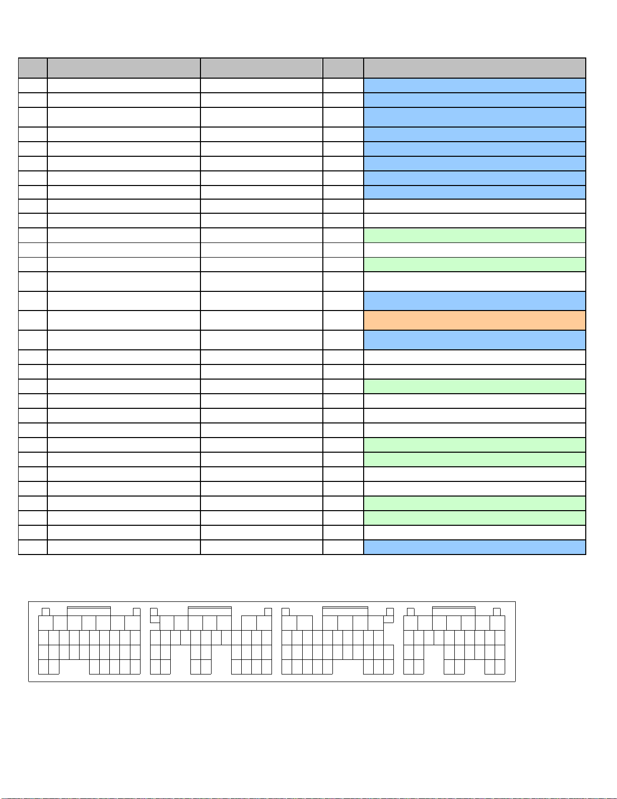
Wire View Of AEM EMS
2932 3031 28
17
24252627
3334
1716151413121110
31
23
3534
2627
32
2122 20
30
7 6 5 34 2 1
89
2829
1819
2425
33
8910111213141516
18
28
27 22
3234
2526 2423
3031 29
2021 19
6 5 4 3 2 1
7
17
35 33
891011121314151617
18
2631
22
2830
2524 23
27
2021 19
7 6 5 4 3 2 1
29
Page 17 of 21
Page 18
Pin
2004 STI 2.5L / 2005-2006 STI 2.5L
AEM EMS
30-6820
EMS
I/O
EMS pin description
B1
GND (Power Supply)
Power Ground
In
Dedicated, also A34,B4,B12,B31,C32,C33,D1,D2,D7,D31
B2
Rear Oxygen Sensor heater signal
---
Not Used
B3
---
---
Not Used
B4
GND (Power Supply)
Power Ground
In
Dedicated, also A34,B1,B12,B31,C32,C33,D1,D2,D7,D31
B5
Control Unit Power Supply
+12V Switched Ignition Power
In
Dedicated, also connects to A18, A19, B6
B6
Control Unit Power Supply
+12V Switched Ignition Power
In
Dedicated, also connects to A18, A19, B5
B7
---
---
Not Used
B8
Camshaft position sensor (LH)
Vehicle Speed
In
PnP for Cam sensor (LH)
B9
Camshaft position sensor (RH)
Cam
In
PnP for Cam sensor (RH)
B10
Crankshaft position sensor Signal (+)
Crank
In
Dedicated
B11
---
---
Not Used
B12
GND (Ignition System)
Power Ground
In
Dedicated, also A34,B1, B4,B31,C32,C33,D1,D2,D7,D31
B13
---
Coil 6
Out
Available Coil 6 output, 0/5V falling edge trigger
B14
---
Coil 5
Out
Available Coil 5 output, 0/5V falling edge trigger
B15
Ignition Control #4
Coil 4
Out
PnP for Coil 4, 0/5V falling edge trigger
B16
Ignition Control #3
Coil 3
Out
PnP for Coil 3, 0/5V falling edge trigger
B17
Ignition Control #2
Coil 2
Out
PnP for Coil 2, 0/5V falling edge trigger
B18
Ignition Control #1
Coil 1
Out
PnP for Coil 1, 0/5V falling edge trigger
B19
Back-up Power Supply
Permanent +12V
In
Dedicated, back-up power for internal datalog memory
B20
---
---
Not Used
B21
---
---
Not Used
B22
Crankshaft position sensor Signal (-)
Timing Ground
Out
Dedicated, timing sensors only
B23
---
---
Not Used
B24
Radiator Fan relay 2 control
Low Side 9
Out
PnP for A/C Fan
B25
Radiator Fan relay 1 control
Low Side 8
Out
PnP for Radiator Fan
B26*
Fuel Pump control unit Signal 1 /
Vehicle Speed*
FPCU circuit (Coil 8) / Spare
Speed*
Out*
Dedicated, 0-5V signal to Fuel Pump Control Unit
B27*
Vehicle Speed / Fuel Pump control unit
sig 1*
Spare Speed / FPCU circuit
(Coil 8)*
In*
PnP for wheel speed input, shared with speedometer
B28
---
CANH
Dedicated
B29
---
CANL
Dedicated
B30
---
---
Not Used
B31
Crankshaft Position sensor Shield
Power Ground
Out
Dedicated, also A34,B1, B4,B12,C32,C33,D1,D2,D7,D31
B32
---
---
Not Used
B33
A/C relay control
Low Side 6
Out
PnP for A/C compressor clutch
B34
---
High Side 1
Out
Available switched +12V output driver
B35
Electronic Throttle control motor relay
ETC relay control
Out
Dedicated
1234567
8910111213141516
181920212223
Connector DConnector CConnector BConnector A
Wire View Of AEM EMS
2932 3031 28
17
24252627
3334
1716151413121110
31
23
3534
2627
32
2122 20
30
7 6 5 34 2 1
89
2829
1819
2425
33
8910111213141516
18
28
27 22
3234
2526 2423
3031 29
2021 19
6 5 4 3 2 1
7
17
35 33
891011121314151617
18
2631
22
2830
2524 23
27
2021 19
7 6 5 4 3 2 1
29
Page 18 of 21
Page 19

Pin
2004 STI 2.5L / 2005-2006 STI 2.5L
AEM EMS
30-6820
EMS
I/O
EMS pin description
C1
---
Injector 6
Out
Available, can be used for additional injectors (1.5A max)
C2
---
Injector 5
Out
Available, can be used for additional injectors (1.5A max)
C3
Fuel Injector #4
Injector 4
Out
PnP for Injector 4 (Peak & Hold 4A / 1A driver)
C4
Fuel Injector #3
Injector 3
Out
PnP for Injector 3 (Peak & Hold 4A / 1A driver)
C5
Fuel Injector #2
Injector 2
Out
PnP for Injector 2 (Peak & Hold 4A / 1A driver)
C6
Fuel Injector #1
Injector 1
Out
PnP for Injector 1 (Peak & Hold 4A / 1A driver)
C7
Main switch
Main Switch
In
Dedicated, ETC system input
C8
Brake Switch 2
---
Not Used
C9
Brake Switch 1
Switch #2
In
Available, switch should connect to GND when closed
C10
Resume / Accel switch
---
Not Used
C11
Set / Coast switch
Set Switch
In
Dedicated, ETC system input
C12
Fuel Temperature Sensor signal
EGT #1
In
Available, jumper set for 0-5V input
C13
Intake Air Temperature sensor signal
AIT
In
PnP for Air Intake Temp sensor, RTD type thermistor
C14
Engine Coolant Temperature sensor
Coolant
In
PnP for Coolant Temp sensor, RTD type thermistor
C15
Accelerator Pedal Position sensor
Power
Accelerator Pedal +5V
reference
Out
Dedicated, reference power to accelerator pedal
C16
Electronic Throttle control Power
Supply
+5V Sensor reference
Out
Dedicated, sensor reference power
C17
Accelerator Pedal Position sensor Main
Accelerator Pedal signal 1
In
Dedicated, main 0-5V signal from accelerator pedal
C18
Electronic Throttle control Main
TPS / Electronic Throttle signal
1
In
Dedicated, main 0-5V signal from throttle motor
C19
---
---
Not Used
C20
Fuel Level Sensor
---
Not Used
C21
Fuel Tank Pressure Sensor signal
---
Not Used
C22
Manifold Absolute Pressure sensor
signal
MAP
In
PnP for Manifold Pressure sensor
C23
Mass Air Flow sensor Signal
MAF
In
Available, 0-5V MAF input signal
C24
--
Knock 2
In
Dedicated, software – configurable knock filter circuit
C25
Knock Sensor Signal
Knock 1
In
Dedicated, software – configurable knock filter circuit
C26
Tumble Generator Valve position
sensor LH
ADCR14
In
PnP for TGV, 0-5V input
C27
Tumble Generator Valve position
sensor RH
ADCR11
In
PnP for TGV, 0-5V input
C28
Accelerator Pedal Position sensor Sub
Accelerator Pedal signal 2
In
Dedicated, secondary 0-5V signal from accelerator pedal
C29
Electronic Throttle control Sub
Electronic Throttle signal 2
Out
Dedicated, secondary 0-5V signal from throttle motor
C30
---
---
Not Used
C31
Mass Air Flow sensor GND
Sensor Ground
Out
Dedicated, sensors only, connects to pin A4, C35,
C32
Mass Air Flow sensor Shield
Power Ground
Out
Dedicated, also A34,B1, B4,B12,B31, C33,D1,D2,D7,D31
C33
Knock Sensor Shield
Power Ground
Out
Dedicated, also A34,B1, B4,B12,B31,C32,D1,D2,D7,D31
C34
Accelerator Pedal Position sensor GND
Accelerator Pedal Ground
Out
Dedicated, ground to accelerator pedal
C35
GND (sensor)
Sensor Ground
Out
Dedicated, sensors only, connects to pin A4, C31,
1234567
8910111213141516
181920212223
Connector DConnector CConnector BConnector A
Wire View Of AEM EMS
2932 3031 28
17
24252627
3334
1716151413121110
31
23
3534
2627
32
2122 20
30
7 6 5 34 2 1
89
2829
1819
2425
33
8910111213141516
18
28
27 22
3234
2526 2423
3031 29
2021 19
6 5 4 3 2 1
7
17
35 33
891011121314151617
18
2631
22
2830
2524 23
27
2021 19
7 6 5 4 3 2 1
29
Page 19 of 21
Page 20
Pin
2004 STI 2.5L / 2005-2006 STI 2.5L
AEM EMS
30-6820
EMS
I/O
EMS pin description
D1
GND (control systems)
Power Ground
In
Dedicated, also A34,B1, B4,B12,B31,C32,C33,D2,D7,D31
D2
GND (control systems)
Power Ground
In
Dedicated, also A34,B1, B4,B12,B31,C32,C33,D1, D7,D31
D3
Electronic Throttle control GND
(sensor)
Electronic Throttle Ground
Out
Dedicated
D4
Electronic Throttle control motor (-)
Electronic Throttle Motor -
Out
Dedicated, ETC system output
D5
Electronic Throttle control motor (+)
Electronic Throttle Motor +
Out
Dedicated, ETC system output
D6
Electronic Throttle control Motor Power
Electronic Throttle Power
In
Dedicated, ETC power
D7
GND (Injectors)
Power Ground
In
Dedicated, also A34,B1, B4,B12,B31,C32,C33,D1,D2,D31
D8
Starter switch
Main Relay circuit (Switch #1)
In
Dedicated
D9
Neutral Position switch
---
Not Used
D10
Power Steering oil pressure switch
---
Not Used
D11
Rear Defogger switch
Switch #4
In
Available, switch should connect to GND when closed
D12
(not used by stock ECU)
---
Not Used
D13
Blower Fan switch
Switch #5
In
Available, switch should connect to GND when closed
D14*
Test Mode Connector / Ignition Switch*
--- / Main Relay circuit
(Switch1)*
*
Not Used
D15*
Ignition Switch / Test Mode Connector*
Main Relay circuit (Switch 1) / -
-- *
In*
Dedicated
D16*
AC Switch / Main Relay control*
Switch 6 / Main Relay circuit
(Coil 7) *
In*
PnP for A/C request switch
D17*
Main Relay control / AC Switch*
Main Relay circuit (Coil 7) /
Switch 6 *
Out*
Dedicated, activates main relay with switched GND
D18
---
---
Not Used
D19
---
---
Not Used
D20
SSM / GST communication line
EGT #2
In
Available, jumper set for 0-5V input
D21
---
---
Not Used
D22
---
---
Not Used
D23
---
---
Not Used
D24
Blow-by Leak diagnosis signal
EGT #3
In
Available, jumper set for 0-5V input
D25
Rear Oxygen sensor Signal
Lambda #2
In
Available, 0-5V O2 #2 signal
D26
---
---
Not Used
D27
---
---
Not Used
D28
Fuel Pump control unit Signal 2
Low Side Driver #5
Out
Available, can be used for Switched Ground (1.5A max)
D29
--
EGT #4
In
Available, jumper set for 0-5V input
D30
---
---
Not Used
D31
Rear Oxygen sensor Shield
Power Ground
Out
Dedicated, also A34,B1, B4,B12,B31,C32,C33,D1,D2,D7
1234567
8910111213141516
181920212223
Connector DConnector CConnector BConnector A
Wire View Of AEM EMS
2932 3031 28
17
24252627
3334
1716151413121110
31
23
3534
2627
32
2122 20
30
7 6 5 34 2 1
89
2829
1819
2425
33
8910111213141516
18
28
27 22
3234
2526 2423
3031 29
2021 19
6 5 4 3 2 1
7
17
35 33
891011121314151617
18
2631
22
2830
2524 23
27
2021 19
7 6 5 4 3 2 1
29
Page 20 of 21
Page 21

AEM Electronics Warranty
Advanced Engine Management Inc. warrants to the consumer that all AEM Electronics
products will be free from defects in material and workmanship for a period of twelve
months from date of the original purchase. Products that fail within this 12-month warranty
period will be repaired or replaced when determined by AEM that the product failed due to
defects in material or workmanship. This warranty is limited to the repair or replacement of
the AEM part. In no event shall this warranty exceed the original purchase price of the
AEM part nor shall AEM be responsible for special, incidental or consequential damages
or cost incurred due to the failure of this product. Warranty claims to AEM must be
transportation prepaid and accompanied with dated proof of purchase. This warranty
applies only to the original purchaser of product and is non-transferable. All implied
warranties shall be limited in duration to the said 12-month warranty period. Improper use
or installation, accident, abuse, unauthorized repairs or alterations voids this warranty.
AEM disclaims any liability for consequential damages due to breach of any written or
implied warranty on all products manufactured by AEM. Warranty returns will only be
accepted by AEM when accompanied by a valid Return Merchandise Authorization (RMA)
number. Product must be received by AEM within 30 days of the date the RMA is issued.
Please note that before AEM can issue an RMA for any electronic product, it is first
necessary for the installer or end user to contact the tech line at 1-800-423-0046 to
discuss the problem. Most issues can be resolved over the phone. Under no
circumstances should a system be returned or a RMA requested before the above process
transpires.
AEM will not be responsible for electronic products that are installed incorrectly, installed
in a non approved application, misused, or tampered with.
Any AEM electronics product can be returned for repair if it is out of the warranty period.
There is a minimum charge of $75.00 for inspection and diagnosis of AEM electronic
parts. Parts used in the repair of AEM electronic components will be extra. AEM will
provide an estimate of repairs and receive written or electronic authorization before repairs
are made to the product.
Page 21 of 21
 Loading...