

Page 1

SANTO
ARCTIS
Integrierbare Unterbau-Kühl- und
Gefriergeräte
Réfrigérateurs et congélateurs sous-plan
à intégrer
Geïntegreerde onderbouwkoel- en
vriesapparaten
Integrated built-under refrigerators and
freezers
Integrerbara underbänk-kyl- och frysskåp
Työtason alle asennettavat jääkaapit ja
pakastimet
Frigoriferi e congelatori sottotavolo da
incasso
D
Montageanweisung 2-10
F
Instructions de montage 11-19
N
Montage-aanwijzing 20-28
t
Installation instructions 29-37
S
Monteringsanvisning 38-46
q
Asennusohjeet 47-55
I
Istruzioni di montaggio 56-63
Page 2
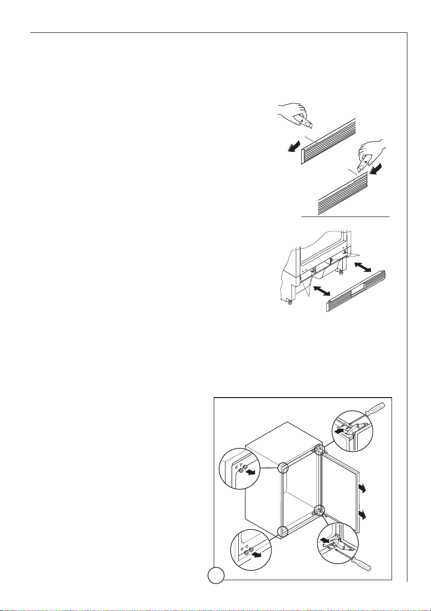
Grid preparation
t
When changing the side at which the door opens, remove plug from
the mains.
Left door opening:
☞
Remove the left side (A) of the grid cutting
it from the rear (see figure)
Right door opening:
☞
Remove the right side (B) of the grid cutting
it from the rear (see figure)
Re-install the grid to the base of the appliance by pushing on to the clasps (a) until
they click.
To reverse the opening direction of the door, proceed as
shown in the figures:
29
Reversing the door
The side at which the door opens can be changed from the right side
(as supplied) to the left side, if the installation site requires.
1
1
2
3
4
5
A
DO002/2
a
B
a
Page 3
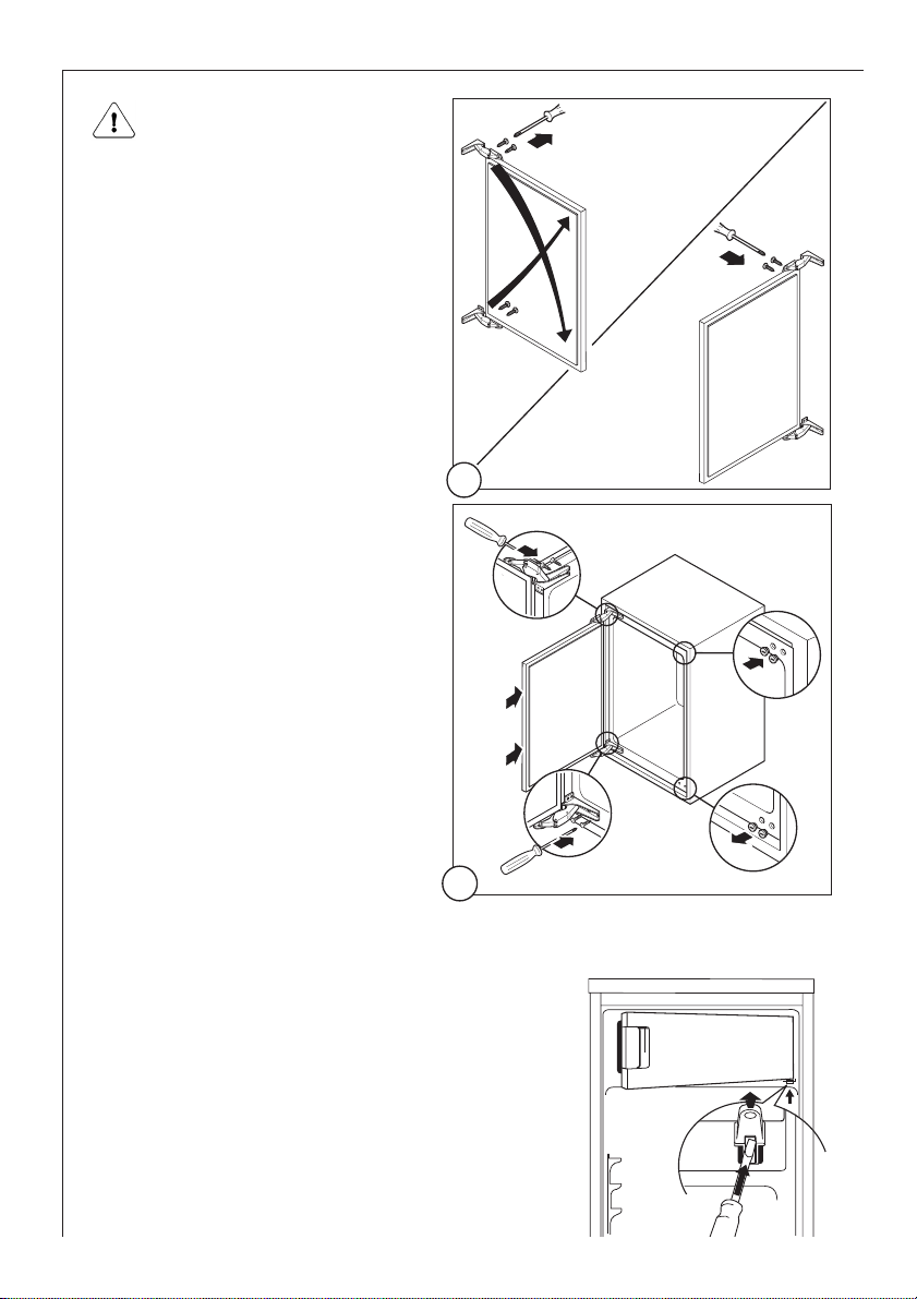
Changing over the freezer compartment door
(not on all models)
30
6
8
7
2
Warning! After completion of
the door reversing operation,
check that the door gasket
adheres to the cabinet. If the
ambient temperature is cold
(i.e. in Winter), the gasket
may not fit perfectly to the
cabinet. In that case, wait for
the natural fitting of the
gasket or accelerate this process by heating up the part
involved with a normal hairdryer on a low setting.
☞ Open the freezer compartment door a
little way.
Using a small screwdriver, press the
spring in the opening of the lower door
bearing slightly upwards and take the
door bearing out complete with the
door.
☞
10
13
9
12
11
3
Page 4
31
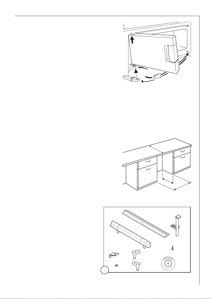
Position the covering cap (M) on the
opposite side.
Turn the freezer compartment door
through 180° and fit the lower door
bearing into the lower bearing cavity
of the freezer compartment door.
Lift the freezer compartment door a
little way upwards, fit it into the
upper door bearing, and at the same
time insert the lower door bearing
into the square hole. Small upwards
and downwards adjustments of the
freezer compartment door will make
fitting easier.
☞
☞
☞
Installation kit
Building the appliance in under a worktop
The dimensions of the recessed
installation area must correspond
with those indicated in the figure.
☞
M
600
550
min.
600
1xB
1xA
2
2
1
1
1
2xC
12
2
Page 5

32
Two cabinet securing brackets are supplied with the
installation pack. They need
to be assembled onto the
cabinet prior to cabinet
being pushed into the
Kitchen aperture.
To fit these brackets remove
the two screws at the top
☞
☞
Right hand
bracket
1/a
Left hand
bracket
Push the appliance into
place. The plug socket
necessary for connection
of the appliance to the
electricity supply should be
positioned, so that the
plug is not placed in the
recess.
To adjust the height proceed as follows:
Loosen or tighten the two
front feet.
☞
☞
2
If necessary, pads are supplied for the
rear feet to make sliding the appliance
in and out of the recess easier. To fit the
pads, press them onto the rear feet.
If required, the dimensions of these
pads can be reduced by breaking them
where marked.
☞
2/a
left and right hand front corners of the cabinet.
Position the two brackets as shown in the figure and replace the two
securing screws.
☞
The rear feet are adjusted by turning the screw in the front kick plate
to the left or right.
☞
596
555
max
-
Li89
+
II52
Page 6

33
Screw appliance into place
5
☞
The joint cover (B) is to be
assembled after having
installed the appliance in the
recess.
2
B
3
4
1
115°
Page 7

34
Mounting furniture door
7
6
a
b
10
1
2
3
4
C
8
ab
clic
clic
c
C
C
Page 8

35
10
1
2
3
45
°
11
=
=
10
Upper part of kitchen furniture panel
9
b
a
=
=
1
2
Lower part of kitchen furniture
panel
9/a
275 275
max 100
Page 9

36
Refit the covering strip.
☞
12
A
13
Page 10

37
Fitting the plinth
Important!
For the efficient operation of the appliance, it is important that the original
ventilation grid is used.
• For an opening height dimension
A=820 mm and a plinth height
dimension a=100 mm, the plinth
may be fitted without adjustments.
The same applies to an opening
height dimension B=870 mm and a
plinth height dimension b=150 mm.
• For plinth heights greater than
a=100 mm, b=150 mm, a cut should
be made in the plinth, 580 mm wide,
in the centre of the appliance
position, leaving a remaining height
of a=100 mm, b=150 mm.
• Attach plinth to the kitchen units.
Important! The plinth must be positioned at a minimum distance of
25 mm from the door.
A = 820
B = 870
25
25 - 80
580
a = 100
b = 150
Page 11

AEG Hausgeräte GmbH
Postfach 1036
D-90327 Nürnberg
http://www.aeg.hausgeraete.de
© Copyright by AEG
Änderungen vorbehalten
Sous réserve de modifications
Wijzigingen voorbehouden
Subject to change without notice
Med reservation för ändringar
Oikeus muutoksiin pidätetään
2221 611-13 -01- 0203 Con riserva di modifiche
 Loading...