

Page 1
Do-It-
Yourself
Planning &
Installation
Manual
for your new
AFUERA
TM
Central
Cleaning
System
Page 2
Before you start, read these instructions
thoroughly.You will be pleased to learn that a
central cleaning system is surprisingly easy
to install, and will provide you with years of
trouble-free enjoyment. All central cleaning
systems may be installed in either existing
or new construction. In either case, the number of inlets required and their locations
must be determined before starting the
installation.
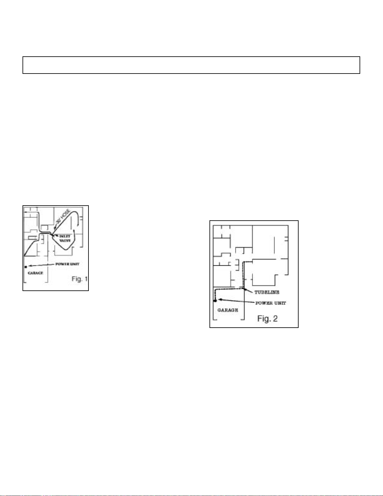
STEP 1: Choose the Valve Locations
Choose central locations for inlet valves in order to
cover the maximum area with the deluxe 30 foot
(9m) length hose. Usually several rooms (or The
Entire Main Floor) can be
serviced from a single inlet
valve (Fig. 1). There is an
inlet valve on the power unit
itself, and this feature often
reduces, by one, the number of inlets required. Since
floor plans are normally
drawn to 1/4" scale (1 to
50cm), a 7-inch (18cm)
piece of string or beaded
chain will help to determine
inlet valve locations and hose coverage using the
floor plans of the construction. If the building is existing or under construction, use a 30 foot (9m) tape or
rope. Be sure every inch of floor, wall, closet, and
ceiling can be reached, bearing in mind the hose
may have to reach around large pieces of furniture.
Good locations are centrally located in hallways or
closet walls near doorways. Inlets should be
installed near an electrical outlet (no more than 6 ft.
(1.82m) away). This would allow the use of an electric hose without using a drop cord. Caution—Do
not place inlet valves where a door slides in the
wall,behind possible furniture, or behind open
doors. In existing homes, consider whether you will
want floor inlets or wall inlets. Floor valves are more
easily installed than wall valves and sometimes are
the only practical installation. They have some disadvantages as the hose must be inserted at the floor
level rather than at a more convenient wall height.
Wall height is a matter of individual preference.
Some homeowners prefer the inlet at a convenient
fingertip height (about 30 inches (76cm)), while others want it to match the electric outlet height.
STEP 2: Choose Power Unit Location
The power unit can be mounted on almost any wall.
It should be out of the way , yet accessible, so the dirt
receptacle may be emptied. If you plan to exhaust
the power unit, locate it so piping can be run outside
conveniently. Venting over 10 ft. (3m) is not recommended. You will need to plug your power unit into
an electric outlet with no other loads on the circuit or
you may want to run a separate 15 amp. circuit.
STEP 3: Plan the Tube System
Plan the entire tubing installation from the power unit
to the desired location of the valve(s) (Fig. 2). It is
best to run tubing under the floor in structures with
basements or adequate crawl space. In locations
with no under-floor access, tubing may be run “up”
to the attic and over
to the power unit
using the same precautions and basic
procedures as with a
“down” system. In 2or 3-story existing
structures, tubing
can be run to upper
levels, through
clothes chutes, back
corners of closets,
under stairways,
beside soil
pipes, beside chimneys, or in partition walls before
the drywall goes on. The system that uses the least
amount of bends and tubing should be used.
STEP 4: Tools Required
a) 1/2" (1.3cm) Electric Drill
b) 2-1/4" (5.7cm) Hole Saw or Cutter
c) Steel Tape Measure
d) Screwdriver (Phillips)
e) Screwdriver (Common Blade)
f) Wire Cutters
g) Common Hacksaw or Small Handsaw
h) Hammer i) Masonry Drill Bit
j) Chisel k)Pocket Knife
l) Metal Coat Hanger m)Electrical Tape
n) Razor Knife
A. How to Plan Your New Central Cleaning System
Page 3
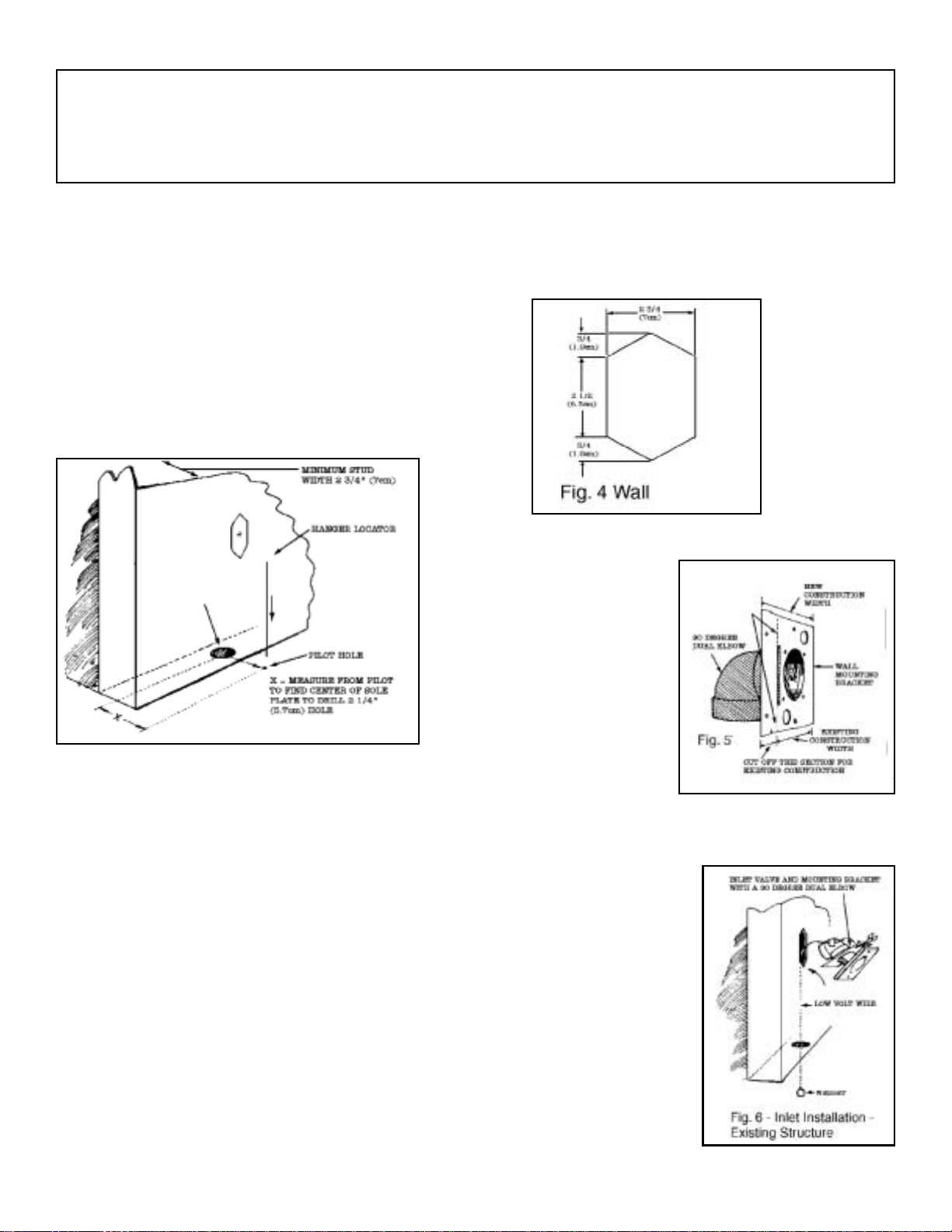
STEP 1: Installing Inlet Valves
a) Wall Valves in Existing Structure
Determine as closely as possible desired location
of inlet valve. Drill a small pilot hole in the floor
directly below the proposed valve location. A
straight length of coat hanger wire, cut at an
angle, makes a good pilot hole drill bit, but, be
careful not to snag carpeting. Leave straightened
length of coat hanger wire through this pilot hole
to serve as locator and guide point (Fig. 3).
From beneath floor, measure over from pilot hole
to
locate the center of the sole plate.
NOTE: You may want to drill a 3/4" (1.9cm)
inspection hole to avoid drilling into the bottom of
a stud or other “inner-wall” obstruction. Drill a 21/4" (5.7cm) diameter hole through the center of
the sole plate. Using a flashlight or probe, inspect
the interior of the wall to be sure there are no
obstructions.
NOTE: The opening you are going to cut in the
wall for the inlet valve should be located between
studs, clear of obstructions such as plumbing,
wiring, heat ducts, etc. Minimum stud width for
sufficient clearance for inner-wall mountingbracket assembly is 2-3/4" (7cm). (See Fig. 3
above.)
b) Using METAL Stud-Mounting Bracket
Centered at the desired height above floor level,
cut an almost square opening 2-3/4" (7cm) wide
by 2-1/2" (6.35cm) high in the wall directly above
the 2-1/4" (5.7cm) sole plate hole. Cut or file two
3/4" (1.9cm) high triangular pieces above and
below the almost square opening so that your wall
opening exactly resembles (Fig. 4). Insert top
screw only through inlet valve and gently squeeze
inlet valve stem
into bracket
assembly until
you are able to
just start top
screw threads in
bracket assembly hole.
Now cut or break
off “New
Construction”
section from
metal wall mounting bracket and glue a 90 degree
dual elbow to the
pre-riveted
adapter ring
(Fig. 5). Strip the
low-volt wire and
tape it to the 90
degree dual elbow
with approximately
6 inches (15.3cm)
sticking through
wire guide hole.
Join two inlet valve
wires with wire
connectors supplied. Attach a
small weight to the
other end of the
low-volt wire and drop
the weighted wire
through the opening
in wall. Allow wire and
weight to hang
through sole plate
(Fig. 6).
B. How to Install Your New Central Cleaning
System
Page 4

insert assembled 90 degree dual elbow and
wall-bracket assembly through wall cutout hole
as illustrated (Fig. 7).
Once metal mounting bracket is completely inside wall
cavity, slide the
entire assembly
upwards so metal
plate is flush with
inner wall surface
and inlet valve is
flush with outer wall
surface. You can
insert index finger
through inlet valve opening and gently squeeze
inlet valve stem further into inner wall assembly
(Fig. 8).
NOTE: Mount inlet
valve so lid pulls
down to open.
Now, insert and
partially tighten
bottom\Inlet valve
screw. Tuck lowvoltage wires and
connectors under
sides of wall inlet
valve. Adjust inlet
valve for perfect
vertical alignment
and tighten both
inlet valve mounting screws. Be sure the inlet
valve lid operates freely. Apply glue to an adequate length of tubing and aim it upwards
through the hole and into the 90 degree dual
elbow fitting on the back of the mounting plate.
Join this branch line to the trunk line using a 90
degree sweep tee.
If the inlet valve is to be serviced from the attic,
shorter pieces of tubing joined by couplings
may be required due to overhead space restrictions. Precut these pieces and work quickly to
prevent the cement on the end of the tubing
from drying before it reaches the fitting at the
valve below.
c) Using PLASTIC Stud-Mounting
Bracket
Having determined the location is suitable, cut
a 2- 1/2" (6.35cm) x 4-3/8" (11cm) hole in the
wall at the
desired inlet
valve location (See Fig.
9).
Now cut or
break off
“new construction”
section from
plastic wall
mounting
bracket.
Tape low-
voltage wire
to the end of a sufficiently long piece of tubing
and pass it up from beneath. If the trunk line is
in the attic, tie a weight to the end of the lowvoltage wire and lower it through the opening.
Remove the wire and pass it through the upper
hole in the trimmed mounting plate. Bare an
inch of both wire leads and wrap them around
the lugs on the back of the valve in a clockwise
direction. Tighten the lugs with a Phillips screwdriver.
Apply cement to the flange on the back of the
mounting plate
and attach a
90 degree
dual elbow fitting oriented in
the appropriate direction.
Tilt the mounting plate forward and
angle it into
the hole in the
wall. Center
the mounting
plate in the
hole and pull
outward (See Fig. 10).
Page 5

Hold the mounting plate in place with a bent
coat hanger. Open the valve lid and slide the
valve flange first over the end of the coat hang-
er. Keep tension on the coat
hanger while
inserting the
valve into the
mounting plate
with a twisting
motion (See
Fig. 11). Do not
use glue; the
built in mounting plate gasket
will provide a
positive seal.
Align the screw
holes in the valve with those in the mounting
plate. Using the screws provided, secure the
valve in place. Use the extra short screw if the
longer is going to interfere with the tubing
behind. Do not over tighten.
Apply glue to an adequate length of tubing and
aim it upwards through the hole and into the 90
degree dual elbow fitting on the back of the
mounting plate. Join this branch line to the trunk
line using a 90 degree sweep tee.
If the inlet valve is to be serviced from the attic,
shorter pieces of tubing joined by couplings
may be required due to overhead space restrictions. Precut these pieces and work quickly to
prevent the on the end of the tubing from drying
before it reaches the fitting at the valve below.
d) Floor Valves
To install a floor inlet, drill a pilot hole with a coat
hanger and check the location as previously
described. When you are sure that the proposed location will not be blocked by a joist or
other obstruction, cut a hole in the carpet slightly larger than your 2-1/4" (5.7cm) drill bit. Drill a
2-1/4" (5.7cm) hole in the floor. Chisel or saw
this hole larger to accommodate the inlet valve
low-volt connections (Fig. 12).
Assemble an adapter reducer bushing and
some low-volt wire to an inlet valve. Screw the
valve to the floor. Repeat until all inlets are
installed (Fig. 13).
e) Closet Wall Installation—Existing
Structure
Often it is only practical to install your system
with the line coming up through the floor inside
a closet and
then through
both sides of
the wall. To use
this method,
select suitable
inlet valve
location, exercising same
precautions as
for normal wall
installation.
Using a length
of coat hanger,
pierce a hole
through both
walls (Fig. 14).
Page 6

Be sure to hold wire perfectly horizontal so that
both interior and exterior holes line up with one
another. Check for inner wall obstructions by
bending short length of coat hanger wire at a
right angle and twirling this right angle piece
inside the wall.
Drill a 2 1/4" (5.7cm) hole horizontally through
both sides of wall.
Make the hole in the exterior wall surface into
the same shape opening as described previously in
STEP 1 - (Installing Inlet Valves) (Fig. 4).
From inside closet, cut 2-1/4" (5.7cm) hole
through floor, either directly below opening in
wall or at convenient spot. (Caution: - Make
pilot hole as in STEP 1 previously.) Run lowvoltage wire through 2-1/4" (5.7cm) hole in
floor, and through wall to exterior of closet.
Pass low-voltage wire through the wire guide
hole of the inner wall closet assembly (Fig.
15) and tape low-voltage wire to this assembly
immediately behind the metal bracket.
Attach wires to low-voltage terminals at rear of
inlet
valve.
Place inner wall assembly lengthwise through
wall opening and arrange assembly so that
metal bracket is flush with inside surface of
wall. Screw inlet to wall as described previously in STEP 1, then complete as per (Fig. 16).
f) Wall V alve Installation—New Construction
Select a probable location for inlet valve and
drill a pilot hole in the floor. Go below to check
that tubing path is clear of present, or future,
obstructions such as floor joists, heating ducts,
plumbing, wires, etc.
At intended inlet valve location, drill a 2-1/4"
(5.7cm) diameter hole through sole plate. To
pinpoint center of hole, measure over 2"
(5.1cm) from side of stud and 2" (5.1cm) from
front of sole plate (Fig. 17).
Glue a length of tubing into a stud-mounting
bracket assembly. Cut a length of low-voltage
wiring, bring approximately 6" (15.24cm)
through top wire guide hole in stud bracket
assembly and double it back into elbow hole.
Tape wire to tubing at assembly elbow and
again close to end, and tuck remaining wire
into bottom of tubing.
Page 7

Screw plaster guard onto face of assembly
(See Fig. 18).
Drop bottom of tubing through 2-1/4" (5.7cm)
hole and nail stud mounting bracket assembly
to stud. Make sure center of inlet hole is at the
correct height above floor level and tubing
extends below sub-flooring.
Be sure to install a nail guard when holes are
drilled through the sole or top plates. This is to
prevent a nail or screw from penetrating the
vacuum tubing. Go to STEP 2 “Installation of
Tube System” and complete tubing system as
much as possible.
After the walls are finished and painted, the
plaster guards will be removed and inlet valves
installed. The tubing system may be completed
at that time and the power unit installed.
STEP 2: Installation of Tube System
(New or Existing Structure)
Starting at the inlet furthest from the power unit,
temporarily fasten the main line in position.
(Good idea: - From a nail or overhead pipe,
etc., make two loops of string or low-voltage
wire to pass PVC tubing through, to hold it in
position while you work.)
Push a length of PVC tubing up into bottom of
inlet valve assembly. Bear in mind, tube enters
all fittings approximately 3/4" (1.9cm). Measure,
cut, and slip-fit this vertical line to main horizontal line with a 90 degree sweep elbow.
To avoid potential clogging problems when
installing tubing and fittings, here are some recommendations:
• Always make straight cuts on tubing
• Always remove burrs from end of tubing.
• Be sure tubing fits against shoulder of fitting
with no gaps.
• Glue tubing side only before assembly into
fittings.
Connect additional inlet valves to main trunk
line with the 90 degree sweep tee (Fig. 19).
Be sure to install sweep tee fittings so sweep
is towards power unit (Fig. 20).
Always run branch lines, from sides or top of
main trunk line, never out of the bottom, as this
will create a trap for dirt to fall into.
Bring low-voltage wire along as you assemble
tubing.
Join or splice wire with wire connectors at each
branch or junction in the tubing. Neatly tape
wire to tube. Proceed until the tubing system is
complete.
Page 8

STEP 3: Installation of Power Unit
The power unit is screwed to the wall with the
bottom screws of the mounting bracket located
48" (1.2m) up from the floor to allow convenient
removal of the dirt canister. For proper motor
cooling, there must be at least 12" (30.5cm)
between the unit and the ceiling.
If mounting on plaster or panel walls, be sure
mounting bolts enter studs.
If mounting on concrete wall, drill the wall with a
masonry bit and insert plastic or lead anchors.
As an alternate mounting on concrete walls, 2"
x 4" (5.1 x 10.16cm) studs or plywood may be
suspended from overhead.
With the power unit mounted, strip the low-voltage wire and crimp into the two “slip-on” terminals provided. Connect main tube line to left
side of power unit, with connector and clamp
provided. Do not cement this connection to the
power unit in case you wish to remove at some
future date. Do not install power unit where the
ambient temperature exceeds 120 degrees
Fahrenheit (48.9 degrees C).
NOTE: For top-loading units, follow directions
provided with unit.
This unit may be exhausted to exterior to expel
fumes, germs, and some noise. Use the same
tubing and fittings as before. If vented, the
exhaust air should not be vented into a wall,
ceiling, or concealed
space of a building. Venting over 10 ft. (3m) is
not recommended.
NOTE: On/Off switch on power unit is for the
inlet on power unit only. All other inlets operate
automatically when the hose end is inserted into
the inlet valve or when the switch, which is
located on the hose handle, is turned on.
WIRING
Check local codes but use not less than #14-3
wire. Plug power unit cord into appropriate
120/220/230/ 240V - 50/60 cycle electrical outlet. Be sure line voltage is sufficient to handle a
15 amp. load.
Page 9

WARNING: ELECTRIC SHOCK COULD OCCUR IF USED ON WET SURFACES.
GROUNDING INSTRUCTIONS
This appliance must be grounded. If it should malfunction or breakdown, grounding provides a path of least
resistance for electric current to reduce the risk of electric shock. This appliance is equipped with a cord having an equipment grounding conductor and grounding plug. The plug must be plugged into an appropriate
outlet that is properly installed and grounded in accordance with all local codes and ordinances.
WARNING
Improper connection of the equipment-grounding conductor can result in a risk of electric shock. Check with
a qualified electrician or service person if you are in doubt as to whether
the outlet is properly grounded. Do not modify the plug provided with the
appliance—if it will not fit the outlet, have a proper outlet installed by a
qualified electrician.
This appliance is for use on a nominal 120-volt circuit and has a ground
plug that looks like the plug illustrated in figure 21 for North American
units. For 220/230/240 volt units, consult your local building code/electrician.
Make sure that the appliance is connected to an outlet having the same
configuration as the plug. No adapter should be used with this appliance.
Check power unit On/Off switch and all inlet valves for operation. This
power unit is intended for household and commercial use.
Important Safety Instructions
When using electrical appliances, basic safety precautions should always be followed, including the following:
Read all instructions before using this vacuum.
NOTE: Your Central Cleaning System is U.L. listed and C.U.L. listed for dry pick-up only. To reduce the risk of
electric shock,DO NOT USE outdoors or on wet surfaces.
DANGER—
Always unplug power unit from the electrical outlet before servicing and cleaning.
WARNING— To reduce the risk of bur ns, fire, electric shock, or injury to persons:
1. Keep cord away from heated surfaces.
2. Do not allow to be used as a toy. Close supervision is necessary when this vacuum is used by or near
children.
Page 10

INLET VALVE EXTENSION
(for thick walls metal)
PLASTIC PLASTER
GUARD
(for new structure)
AUTOMATIC INLET VALVE
(plastic or optional metal)
ADAPTER & BRACKET
ASSEMBLY
(new or old structure)
3. Use this vacuum only for its intended use as described in this manual. (Use of attachments not recommended
by the manufacturer may cause fire, electric shock, or injury.)
4. Never operate this vacuum if it has a damaged cord or plug, if it is not working properly, if it has been dropped,
or damaged. Return to service center or have service person examine and repair.
5. Do not pull or carry this power unit by supply cord, use cord as a handle, close a door on cord, or pull cord
around sharp edges or corners.
6. Never disconnect plug by pulling on cord. To disconnect from outlet, grasp the plug, not the cord.
7 Do not put any object into openings. Do not use with any opening blocked; keep free of dust, lint, hair, and
anything that may reduce air flow.
8. Keep hair, face, fingers, and loose clothing away from any openings.
9. Do not pick up cigarettes, live hot ashes, matches or similar materials.
10. Never operate vacuum without dust bag and/or filter in place.
11. To disconnect, turn all controls to the OFF position; then remove plug from outlet.
12. Never handle plug, cord, or power unit with wet hands.
13. Electric shock could occur if used on wet surfaces.
14. Use extra care when cleaning on stairs.
15. Do not use to pick up flammable or combustible liquids such as gasoline or use in areas where they may be
present.
16. For a grounded appliance: “Connect to a properly grounded outlet only. See grounding instructions.”
SA VE THESE INSTRUCTIONS
QUICK CHECK TABLE OF COMMON AND SPECIAL USE PARTS
90 DEGREE DUAL ELBOW
(Use w/above assembly or
as first bend in line. Never
elsewhere.)
COUPLINGS
(joins PVC tubing)
45 DEGREE Y
90 DEGREE SWEEP
ELBOW
45 DEGREE ELBOW
PLASTIC EXHAUST MUF-
FLER
90 DEGREE SWEEP
ELBOW
45 DEGREE ELBOW
with extension
ADAPTER, REDUCER
BUSHING
(for pipe to floor
mounted inlet valve)
T-ADAPTER
(for two story) (for two inlets in
same wall) Use only
w/adapter and bracket
assemblies.
NAIL GUARD
 Loading...