

Page 1
Page 2
GENERAL
Before installing and/or using the hood, read all of the instructions carefully.
Before installing the hood, ensure that the voltage ( V ) and the frequency ( Hz ) indicated on the registration and technical data tag
attached to the inside of the appliance correspond with the voltage and frequency available in the place of installation.
IDENTIFICATION PLATE AND TECHNICAL DATA PLATE:
The identification plate and technical data plate are inside the appliance.
INSTALLATION
The accessories necessary for the installation of the hood can be found inside it. The hood is convertible and it can, therefore, be
installed in either the SUCTION or DEPURATION versions. In the event that the hood is used in its SUCTION version, connect the
opening (125 mm diameter) (Fig. 2) to an evacuation duct directly connected to the exterior and which has a minimum section of
150cm
UNDER NO CIRCUMSTANCES SHOULD THE HOOD BE CONNECTED TO AN EXHAUST VENT OF OTHER APPLIANCES
WHICH USE ENERGY SOURCES OTHER THAN ELECTRICITY (water heaters – boilers – stoves – etc.). The appliance must not be
placed over stoves with upper radiating plates.
ELECTRICAL CONNECTION
The hood is designed to be installed in a fixed and permanent manner. For line voltage and frequency, consult the registration plate on
the inside of the appliance. The power cable (H05VV-F 2x0.75mm
(neutral) of the hood and secured with a clamping screw, must be connected to a suitable and accessible power point carefully attached
by specialised and authorised personnel, who must follow the installation in compliance with the regulations and laws in force which
provide for the placement of an omnipolar switch before the electrical connection, with contact openings of at least 3 mm.
The manufacturer will not be held responsible if the existing Health and Safety regulations, which are necessary for the normal use and
standard operation of the electrical system, are not observed and complied with.
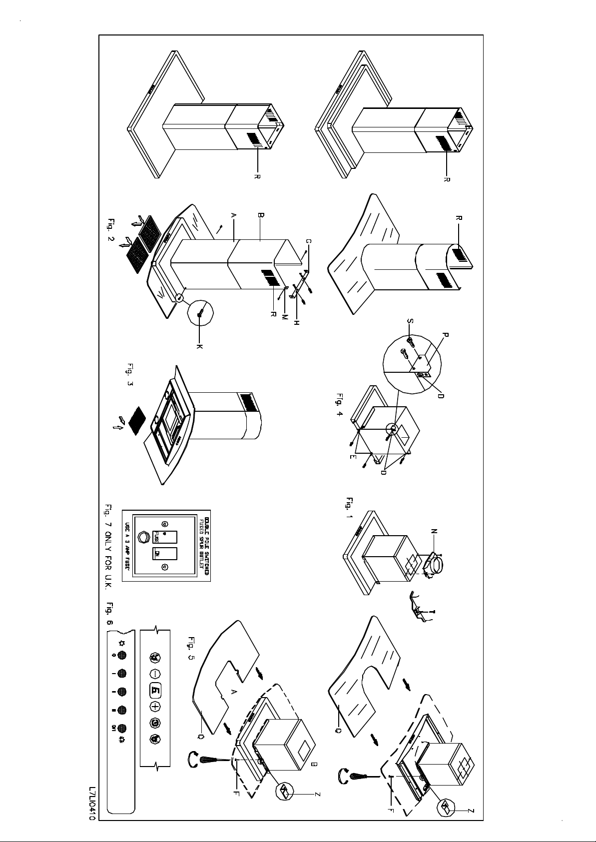
ONLY FOR U.K.:WARNING:THIS APPLIANCE MUST NOT BE EARTHED. This appliance must be connected by competent
person, using fixed wiring via a DOUBLE POLE SWITCHED FUSED SPUR OUTLET.
We recommend that the appliance is connected by a qualified electrician,who is a member of the N.I.C.E.I.C.and who will comply with
the I.E.E.and local regolations.The wires in the mains lead are coloured in accordance with the following code:
Blue = Neutral, Brown = Live.
As the colours of the wires in the mains lead for the appliance, may not correspond with the coloured markings identifying the terminals
in your spur box, proceed as follows:1) The wire which is coloured blue must be connected to the terrninal marked N (Neutral), or
coloured Black.2) The wire which is coloured brown must be connected to the terminal marked L (Live), or coloured Red.
The manufacturer declines all responsibility in the event of failure to observe all the accident-prevention regulations in force which are
necessary for normal use and regular operation of the electric system.
TYPE OF OPERATION
Suction operation
Attach the connector D onto the upper part of the hood by means of the two screws which can be found in the little packet inside the
packaging (FIG. 2).
Connect same by means of a 125 mm tube to the steam and odours’ exhaust vent of the 150cm
In the event that the exhaust vent is not available, make an opening in the wall sufficient enough to attach an anti-rain/air lock, with a
minimum section of 150cm
Air purifier operation
The hood can be transformed into a depuration device in the event of there being no possibility of discharging externally. In this case,
the air re-circulation is carried out by opening R (FIG. 7). For the operation of the hood in its depuration version, it is indispensable to
use an active carbon filter for absorbing cooking odours. The active carbon filter must be periodically changed – at least every three
months under standard operating conditions.
FITTING THE ACTIVE CARBON FILTERS
Before commencing with the insertion of the carbon filter, position the omnipolar switch in the 0 (OFF) position.
Exert pressure on the handle of the anti-grease metallic filter towards the back of the appliance, until same is released from the front
housing and thereafter remove it by exerting pressure towards the base (FIG. 10). Position the carbon filter in the dedicated seat of the
carbon filter support M (FIG. 9). The filter has two tabs at the back for positioning and two at the front for locking. To extract the
carbon filter, press the front tabs towards to the back and remove it by pulling towards the base. (Fig. 9). Re-position the anti-grease
metallic filters.
INSTRUCTIONS FOR ASSEMBLY
INSTRUCTIONS FOR THE INSTALLATION, MAINTENANCE AND USE OF THE HOOD MOD. K71
2
. The hood’s lower surface must be positioned at a distance of at least 70cm from the cooking surface.
2
type) connected to the clamps characterised with L (line), N
2
small section.
2
, and connect same with a tube to the exhaust line of the appliance.
The hood is designed to be ceiling-mounted. The hood must be positioned at a distance of at least 70 cm from the cooking surface. Take
plate A (Fig. 1), lean it against the ceiling and mark the positions of the 4 holes B (see fig. 1); hole C indicates the part of the hood (see
fig. 10.1) which is opposite to the controls. Using an 8 mm drill bit, make holes on the marks referred to previously and thereafter insert the
dowels and attach plate A with the 4 screws (the dowels, screws and washers are all contained in the accessories bag). Attach exit
connector D to the hood using 2 screws (which have been provided) and connect to the room exhaust vent (Fig. 2). Attach 2 of the 4
supporting angles E to the motor housing S with 2 screws each, ensuring that the folds E1 are facing forward (Fig. 3.1), thereafter affix the
other 2 supporting angles E to the rear part of the motor housing but this time the folds E2 must be facing outwards (Fig. 3.2). During this
phase, it is possible to regulate the predetermined height of the hood by fixing the 4 supporting angles E in the dedicated adjustment holes
on the hood.
Install the motor frame joining the 4 supporting angles by means of the stiffener F (positioned as per fig. 3) with 4 screws. Insert the casing
H on the motor frame keeping the vents for filtering operation towards the top and laterally; thereafter, insert casing I over casing H (fig.
4). Lift the entire unit, keeping it slightly back from plate A attached to the ceiling (Fig. 5 and Fig. 5.1). Thereafter push it forward
supporting it towards the ceiling in a way that the vents E1 and E2 of the 4 supporting angles E will insert themselves into the front and
lateral dowels of plate A provided with a backstop (fig. 5, 5.1, 5.1.A and 5.1.B.). Proceed then to attach the motor frame using 8 screws
(Fig. 6 and Fig. 6.1). Carry out the electrical and air discharge tube connection.
Remove the metal filters from the hood. Loosen both screws "F" (Fig. 7.1) (left and right respectively) and remove the fixing angle
identified with letter "Z" (Fig. 7.1) pulling it upwards.
Position glass "Q" on the upper side of the hood. Slide from above, through the horizontal slit corresponding to fixing angle "Z",
previously removed, until the short side of the fixing angle is placed horizontally on the glass. Attach fixing angle "Z" to the lower side of
the appliance, tightening again screws "F" in the hole and attaching them to the appliance.
Make sure that the fixing angle is securely attached by tightening hard. Insert back metal filters.
Connect the ventilation hose with connecting hose "N" (Fig. 2).
Lift the casing H up to the ceiling, so that the upper, lateral holes of the casing correspond with those of the plate, and thereafter affix them
using the 4 screws provided (Fig. 8.1). Lift the lower part of the hood K (Fig. 7) and insert it in the motor frame with the tabs L1 in the
proper dowels, thereafter affixing it with the 10 screws provided (Fig. 9, 9.1).
CONTROL PANEL
The commands panel (Fig. 11) is made up of a push-button panel which is situated on the front part of the hood and comprises :
3 push-buttons for motor control (first, second and third gear)
1 push-button for illuminating light;
1 push-button indicating motor off;
If the commands panel is made up of electronic commands, consult the attached instructions sheet.
MAINTENANCE
Before carrying out any operation, always make sure that the omnipolar switch is in the 0 (OFF) position.
a) Cleaning
Clean the external parts with a non-corrosive liquid detergent. Avoid using abrasive powders or brushes.
b) Changing the light bulb
Before replacing the light, make sure that the appliance is not powered up (position 0 (OFF) of the omnipolar switch). Extract the antigrease metal filters (Fig. 10). In the case of a halogen lamp, before replacing the lamp, remove the support ring of the glass by means of a
screwdriver. Replace the halogen lamp using only spare-parts with a G4 20W max. connection. Remount the glass protection, attaching it
with the suitable ring. In the case of dichroic 12V halogen lamp, replace the lamp using only spare-parts with a GU5.3 20W max.
connection. In the case of a 230V halogen lamp, replace the lamp using only spare-parts with an E14 50W max. connection.
Re-install the anti-grease metal filters.
c) Changing the carbon filter.
See fitting the carbon filter.
d) Cleaning the metal anti-grease filter.
The saturation of grease residues in the metallic filter could cause an increase in inflammability of the system. In order to prevent possible
fires, the metallic filter must be washed according to its use or at least every three months in a dishwasher or in hot water with normal
dishwasher detergent. After it has been well rinsed and dried, re-install the anti-grease metallic filter in its dedicated seat.
REMARKS
The cleaning must be carried out in accordance with the manufacturer's instructions, especially with regard to the deposits on the dirty
surfaces, against a possible risk of fire. Pay careful attention that the hot-plates are always covered in a manner which does not cause the
filter to overheat and to catch fire. Never fry leaving the pot unsupervised: the oil contained in the pot could overheat and catch fire. In the
case of used oil, the risk of spontaneous combustion is greater. It is absolutely forbidden to carry out open-fire cooking (eg. flambé). The
collected air must not be conveyed in a duct used for the discharge of smoke from appliances fed by energy sources other than electricity,
furthermore, adequate aeration must be provided in the room when the hood and appliances fed by energy sources other than electricity are
used at the same time. If the hood is used in suction mode, make sure that the discharge vent is in a good condition if it has not been used
for a long period of time. Remember to comply with existing local regulations and with the regulations of the competent authorities with
regards to the discharge of air to be evacuated when the hood is operating in suction mode. All the recommendations herein provided must
be scrupulously adhered to in order to avoid possible fires.
THE MANUFACTURER DECLINES ALL RESPONSIBILITY IN THE EVENT OF FAILURE TO OBSERVE THE INSTRUCTIONS
GIVEN HERE FOR INSTALLATION, MAINTENANCE AND SUITABLE USE OF THE HOOD.
K717380002.doc
Page 3

COMANDI ELETTRONICI
CARATTERISTICHE:
TOUCH CON
TROL
ELECTRONIC CONTROLS
SPECIFICATIONS:
TOUCH CONT
ROL
ELEKTRONISCHE STEUERUNGEN
EIGENSCHAFTEN
TOUCH CONT
ROL
Tast o :
12 435
I COMANDI ELETTRONICI INSTALLATI SULLA VOSTRA CAPPA ASPIRANTE
SONO DOTATI DI MOLTEPLICI FUNZIONI-CARATTERISTICHE:
-FUNZIONE ON-OFF MOTORE.
PREMENDO IL TASTO NR.1 SI ACCENDE O SI SPEGNE IL MOTORE.
ALL'ACCENSIONE LA CAPPA PARTE AUTOMATICAMENTE IN TERZA
VELOCITA'.
-NR. 6 VELOCITA'.
LA VELOCITA' E' SELEZIONABILE ATTRAVERSO I TASTI NR. 2 E NR. 3 E
VISUALIZZATA DALL'APPOSITO DISPLAY.
-FUNZIONE TIMER.
SERVE PER LO SPEGNIMENTO PROGRAMMATO DI MOTORE E LUCI DOPO 15
MINUTI DALL'ATTIVAZIONE DELLA FUNZIONE CHE SI ATTIVA SCHIACCIANDO
IL TASTO NR. 4. QUANDO IL TIMER E' ATTIVATO SUL DISPLAY LAMPEGGIA UN
PUNTO IN BASSO A DESTRA.
-FUNZIONE ON-OFF LUCE.
PREMENDO IL TASTO NR. 5 SI ACCENDE O SI SPEGNE LA LUCE.
-FUNZIONI PARTICOLARI.
I COMANDI ELETTRONICI INSTALLATI SULLA VOSTRA CAPPA ASPIRANTE
SONO DOTATI DI FUNZIONALITA' AVANZATE DI AIUTO ALLA MANUTENZIONE
ED AL BUON UTILIZZO DEL PRODOTTO.
-INDICAZIONE NECESSITA' DI PULIRE I FILTRI METALLICI.
OGNI 30 ORE DI UTILIZZO IL MICROPROCESSORE, CUORE DEL SISTEMA,
SEGNALERA' ATTRAVERSO UNA "A" LAMPEGGIANTE SUL DISPLAY LA
NECESSITA' DI PULIRE I FILTRI METALLICI ANTIGRASSO, QUESTO PER
GARANTIRE LA MIGLIORE ASPIRAZIONE E LA MIGLIORE IGIENE AMBIENTALE.
PER CANCELLARE IL MESSAGGIO DI AVVERTIMENTO UNA VOLTA PULITI I
FILTRI SI DEVE, A CAPPA COMPLETAMENTE SPENTA, TENERE PREMUTO IL
TASTO NR. 2 PER PIU' DI 5 SECONDI. QUANDO SI PREME IL TASTO APPARIRA'
SUL DISPLAY LA LETTERA "A", ALLO SCADERE DEI 5 SECONDI QUESTA
SCOMPARIRA' ED IL MICROPROCESSORE INIZIERA' NUOVAMENTE A
CONTEGGIARE LE 30 ORE PER UN NUOVO MESSAGGIO DI AVVERTIMENTO.
-INDICAZIONE NECESSITA' DI SOSTITUIRE I FILTRI CARBONE (SE MONTATI).
SE LA CAPPA ASPIRANTE DA VOI ACQUISTATA VIENE UTILIZZATA IN
VERSIONE FILTRANTE E QUINDI UTILIZZA DEI FILTRI CARBONE PER LA
DEPURAZIONE DEI FUMI ASPIRATI, BISOGNA PRIMA DI TUTTO AVVERTITE IL
MICROPROCESSORE DEL SISTEMA ELETTRONICO CHE STA GESTENDO UN
APPARECCHIO IN FUNZIONE FILTRANTE. PER FARE CIO', A CAPPA
COMPLETAMENTE SPENTA TENERE PREMUTO PER PIU' DI 5 SECONDI IL TASTO
NR. 4. QUANDO SI PREME IL TASTO SUL DISPLAY APPARE UN "-" (INDICA CHE
LA CAPPA NON UTILIZZA IL FILTRO CARBONE) CHE DOPO 5 SECONDI
DIVENTA UN "C" (INDICA CHE LA CAPPA UTILIZZA IL FILTRO CARBONE). DA
QUESTO MOMENTO IL MICROPROCESSORE OGNI 120 ORE D’UTILIZZO
SEGNALERA' DI SOSTITUIRE IL FILTRO CARBONE USATO FACENDO
LAMPEGGIARE SUL DISPLAY UNA "C". QUESTO PER GARANTIRE LA MIGLIORE
ASPIRAZIONE E LA MIGLIORE IGIENE AMBIENTALE.
PER CANCELLARE IL MESSAGGIO D’AVVERTIMENTO UNA VOLTA SOSTITUITI I
FILTRI CARBONE SI DEVE, A CAPPA COMPLETAMENTE SPENTA, TENERE
PREMUTO IL TASTO NR. 3 PER PIU' DI 5 SECONDI. QUANDO SI PREME IL TASTO
APPARIRA' SUL DISPLAY LA LETTERA "C", ALLO SCADERE DEI 5 SECONDI
QUESTA SCOMPARIRA' ED IL MICROPROCESSORE INIZIERA' NUOVAMENTE A
CONTEGGIARE LE 120 ORE PER UN NUOVO MESSAGGIO D’AVVERTIMENTO.
Key:
12 435
THE ELECTRONIC CONTROLS FITTED ON YOUR HOOD ARE PROVIDED
WITH SEVERAL FUNCTIONS-SPECIFICATIONS:
MOTOR ON-OFF FUNCTION
BY PRESSING KEY NO. 1 THE MOTOR IS SWITCHED ON AND OFF. WHEN
SWITCHED ON THE HOOD STARTS UP AUTOMATICALLY AT THE THIRD SPEED.
NO. 6 SPEEDS
THE SPEED IS SELECTED USING KEYS NO. 2 AND 3 AND IS VIEWED ON THE
DISPLAY.
TIMER FUNCTION
THIS IS USED FOR PROGRAMMED SHUT-DOWN OF THE MOTOR AND LIGHTS 15
MINUTES AFTER THIS FUNCTION IS ACTIVATED, OBTAINED BY PRESSING KEY
NO. 4. WHEN THE TIMER IS OPERATING A DOT FLASHES IN THE LOWER RIGHTHAND SIDE OF THE DISPLAY.
LIGHT ON-OFF FUNCTION
THE LIGHT IS SWITCHED ON AND OFF BY PRESSING KEY NO. 5.
SPECIAL FUNCTIONS
THE ELECTRONIC CONTROLS FITTED TO YOUR HOOD ARE PROVIDED WITH
ADVANCED FUNCTIONS TO FACILITATE MAINTENANCE AND IMPROVED USE
OF THE PRODUCT.
MESSAGE INDICATING THAT THE METAL FILTERS REQUIRE CLEANING
EVERY 30 HOURS OF USE THE MICROPROCESSOR, WHICH IS THE HEART OF
THE SYSTEM, INDICATES WITH A FLASHING «A» ON THE DISPLAY THAT THE
METAL GREASE FILTERS SHOULD BE CLEANED TO CONSENT THE EXHAUST TO
FUNCTION BETTER AND IMPROVE HYGIENE IN THE ROOM.
TO CANCEL THE WARNING MESSAGE AFTER CLEANING THE FILTERS, SWITCH
OFF THE HOOD, PRESS AND HOLD KEY NO. 2 FOR MORE THAN 5 SECONDS.
WHEN THE KEY IS PRESSED THE LETTER «A» APPEARS ON THE DISPLAY;
AFTER 5 SECONDS THIS DISAPPEARS AND THE MICROPROCESSOR STARTS A
NEW 30-HOUR COUNT-DOWN BEFORE DISPLAYING THE NEXT WARNING
MESSAGE.
MESSAGE INDICATING THAT THE CARBON FILTERS REQUIRE REPLACING (IF
FITTED)
IF THE HOOD YOU PURCHASED IS USED IN THE FILTER VERSION, WITH
CARBON FILTERS TO PURIFY EXHAUST FUMES, THE MICROPROCESSOR OF THE
ELECTRONIC SYSTEM MUST FIRST BE INFORMED THAT IT IS MANAGING AN
INSTRUMENT IN FILTER MODE. TO DO THIS, SWITCH OFF THE HOOD , PRESS
AND HOLD KEY NO. 4 FOR MORE THAN 5 SECONDS. WHEN THE KEY IS PRESSED
«-» APPEARS ON THE DISPLAY (INDICATING THAT THE HOOD IS NOT USING
THE CARBON FILTER). AFTER 5 SECONDS THIS BECOMES A «C» (INDICATING
THAT THE HOOD IS USING THE CARBON FILTER). FROM NOW ON EVERY 120
HOURS OF USE THE MICROPROCESSOR INDICATES THAT THE CARBON FILTER
SHOULD BE REPLACED WITH A FLASHING «C» ON THE DISPLAY. THIS
CONSENTS THE EXHAUST TO FUNCTION BETTER AND IMPROVES HYGIENE IN
THE ROOM.
TO CANCEL THE WARNING MESSAGE AFTER REPLACING THE CARBON FILTER,
SWITCH OFF THE HOOD, PRESS AND HOLD KEY NO. 3 FOR MORE THAN 5
SECONDS. WHEN THE KEY IS PRESSED THE LETTER «C» APPEARS ON THE
DISPLAY AND AFTER 5 SECONDS THIS DISAPPEARS AND THE
MICROPROCESSOR STARTS A NEW 120-HOUR COUNT-DOWN BEFORE
DISPLAYING THE NEXT WARNING MESSAGE.
Tast e :
12 435
DIE AUF IHRER ABZUGSHAUBE INSTALLIERTEN ELEKTRONISCHEN
STEUERUNGEN SIND MIT MEHRFACHEN FUNKTIONEN AUS-GESTATTET:
MOTORFUNKTION ON-OFF
DURCH DAS DRÜCKEN DER TASTE 1 SCHALTET SICH DER MOTOR EIN ODER
AUS. BEIM START BEGINNT DIE HAUBE AUTOMATISCH MIT DER
GESCHWINDIGKEIT AUF DER STUFE 3.
NR.6 GESCHWINDIGKEIT
DIE GESCHWINDIGKEIT WIRD ÜBER DIE TASTEN 2 UND 3 GEWÄHLT UND WIRD
VOM JEWEILIGEN DISPLAY ANGEZEIGT.
TIMERFUNKTION
DIESE DIENT DEM PROGRAMMIERTEN AUSSCHALTEN DES MOTORS UND DER
LAMPEN NACH 15 MINUTEN AB DER AKTIVIERUNG DER FUNKTION, DIE SICH
DURCH DRÜCKEN DER TASTE 4 AKTIVIEREN LÄßT. IST DER TIMER AKTIVIERT,
SO LEUCHTET AM DISPLAY EIN PUNKT RECHTS UNTEN AUF.
LICHTFUNKTION ON-OFF
DURCH DRÜCKEN DER TASTE 5 SCHALTET SICH DAS LICHT AUS ODER EIN.
SPEZIALFUNKTIONEN
DIE AUF IHRER ABZUGSHAUBE INSTALLIERTEN ELEKTRONISCHEN
STEUERUNGEN SIND MIT MODERNEN FUNKTIONEN ZUR WARTUNG UND
KORREKTEN ANWENDUNG DES PRODUKTES AUSGESTATTET.
METALLFETTFILTERREINIGUNGSANZEIGE
NACH 30 ARBEITSSTUNDEN MELDET DER MIKROPROZESSOR, DAS HERZSTÜCK
DES SYSTEMS, ÜBER EIN LEUCHTENDES „A“ AM DISPLAY, DAß DIE REINIGUNG
DER METALLFETTFILTER ERFORDERLICH IST. DADURCH WERDEN OPTIMALE
ABSAUGUNG UND BESTE RAUMHYGIENE GEWÄHRLEISTET.
ZUR DEAKTIVIERUNG DER MELDUNG MUß MAN, NACH ERFOLGTER
REINIGUNG DER FILTER, DIE TASTE 2 FÜR MEHR ALS 5 SEKUNDEN BEI
KOMPLETT AUSGESCHALTETER HAUBE GEDRÜCKT HALTEN. WIRD DIE TASTE
GEDRÜCKT, DANN ERSCHEINT AM DISPLAY DER BUCHSTABE „A“. NACH 5
SEKUNDEN VERSCHWINDET DIESER UND DER MIKROPROZESSOR BEGINNT
ERNEUT MIT DEM ZÄHLEN VON 30 STUNDEN BIS ZUR NÄCHSTEN MELDUNG.
KOHLEFILTERAUSTAUSCHANZEIGE (SOFERN FILTER MONTIERT SIND)
WIRD DIE VON IHNEN ERWORBENE ABZUGSHAUBE IN DER VERSION MIT
FILTER VERWENDET, BZW. VERWENDET SIE DIE KOHLEFILTER ZUR
REINIGUNG DER ABGESAUGTEN DÄMPFE, MUß MAN ALS ERSTES DEN
MIKROPROZESSOR DES ELEKTRONISCHEN SYSTEMS PROGRAMMIEREN, DER
EIN GERÄT MIT FILTERFUNKTION STEUERT. ZU DIESEM ZWECK IST DIE TASTE
4 FÜR MEHR ALS 5 SEKUNDEN BEI KOMPLETT AUSGESCHALTETER HAUBE
GEDRÜCKT ZU HALTEN. WENN SIE DIE TASTE AM DISPLAY DRÜCKEN,
ERSCHEINT EIN „-“ (DIES ZEIGT AN, DAß DIE HAUBE KEINEN KOHLEFILTER
VERWENDET), DAS NACH 5 SEKUNDEN EIN „C“ WIRD (DIES ZEIGT AN, DAß DIE
HAUBE EINEN KOHLEFILTER VERWENDET). VON DIESEM ZEITPUNKT AN
MELDET DER MIKROPROZESSOR ALLE 120 ARBEITSSTUNDEN, DAß DER
VERWENDETE KOHLEFILTER AUSZUWECHSELN IST, WENN AM DISPLAY EIN
„C“ AUFSCHEINT. DIES DIENT OPTIMALER ABSAUGUNG UND BESTER
RAUMHYGIENE. UM DIE MELDUNG ZU DEAKTIVIEREN, MUß MAN BEI
KOMPLETT AUSGESCHALTETER HAUBE DIE TASTE 3 FÜR MEHR ALS 5
SEKUNDEN GEDRÜCKT LASSEN. WIRD DIE TASTE GEDRÜCKT, DANN
ERSCHEINT AM DISPLAY DER BUCHSTABE „C“. NACH ABLAUF VON 5
SEKUNDEN ERLISCHT DIESE UND DER MIKROPROZESSOR BEGINNT ERNEUT,
120 STUNDEN BIS ZUR NÄCHSTEN MELDUNG ZU ZÄHLEN.
F887380040.doc
 Loading...