

Page 1

6000 K, 6010 K, 6040 K,
6050 K, 6051 K
Glaskeramik-Einbau-Kochmulden
Fitted Glass Ceramic Cooking Units
Tables de cuisson vitr océramiques à
encastrer
Piani di cottura componibili in
vetroceramica
Glaskeramiek-inbouwkookplaten
Inbyggda glaskeramik-kokhällar
Kalusteisiin sijoitettavat keraamiset
keittotasot
Einbau- und Gebrauchsanweisung
Installation Directives and Instructions
for Use
Notice de montage et d’utilisation
Istruzioni per il montaggio e per l’uso
Inbouw- en gebruiksaanwijzing
Monterings- och bruksanvisning
Asenus- ja käyttöohje
Page 2

Table of Contents
Fitting Instructions 17
Illustrations 17/18
Before Fitting 19
Fitting 19
Connection 19/20
Safety Instructions 21
For the Fitter 21
For the User 21
Description of Equipment 22
6000 K, 6010 K, 6040 K, 22
6050 K, 6051 K 23
Glass Ceramics 24
Attributes 24
How to Operate 25
The Switch 25
Table of Settings 25
Residual-Heat Display 25
Dual-Circuit Connection 26
GB
The right Pots and Pans 26
General Remarks 26
Cleaning and Care of Glass Ceramics Surfaces 27
Basic Principles 27
Food that has Spilled Over 27
Burned-in Sugar 27
Melted Plastic 27
Spots and Stains 28
Grains of Sand 28
Worn Décor 28
What to do when ... 29
Faults you can Remedy Yourself 29
After Sales Service 29
16
Page 3
Fitting Instructions
RR
22
R
2
RR
22
17
Page 4

Fitting Instructions
R 3
1 = Work Top
2 = Insulation
3 = Placement Area
4 = Tensioning Element
18
Page 5

Before Fitting
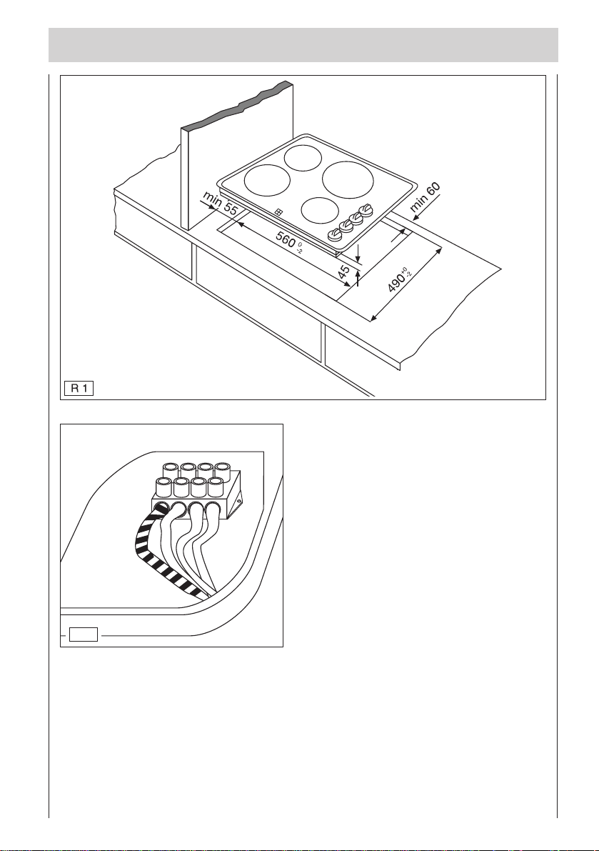
These fitted cooking units are intended for placement in the cutout of a table top
(Illustration 3).
The unit must be connected by an authorized electrician, since this ensures that both
the statutory regulations and the connection conditions of the local electricity supply
company are observed.
Make cutout of 560 mm x 490 mm in the work top with a margin of 55 mm both in front
and behind.
The cooking-unit cupboard must have a protective floor that is at least 30 mm from the
underside of the unit and can only be removed with the use of tools.
Extractor hoods above the unit must be fitted in accordance with the extractor-hood
fitting instructions.
Unit furniture must be treated with a plastic coating or veneer with heat-resistant
adhesive (100 C), as it can otherwise deform or loosen, especially at thinner points.
Fitting
The use of massive wooden wall-side skirting boards on the table top behind the
fitted unit is permissible provided the minimum clearances have been observed.
Alterations of surface colour can be traced to influence of light.
The fitted cooking unit must be installed such that the control switches are positioned
to the right (Illustration 1).
Connection
In cases of electrical connection of the unit, plans must be made for the use of a
facility that enables contact separation from the mains supply of at least 3 mm
for all pins.
Suitable separators are LS switches, fuses and protective devices.
The mains connection cable must be of type H05VV-F or H05VVH2-F at least.
Mains Cable Supply Voltage
230...240 V~ 3 x 4² 230...240 V
400 V 2 N~ 4 x 2.5² 230 V
19
Page 6

Fitting Instructions
1. Place the cooking unit on the working surface with the glass ceramics surface
facing downwards.
2. Remove the covers from the mains connections on the underside of the device;
the terminals for the main line should now be visible. Attach the connecting cable,
using a length of approx. 900 mm, and link to the mains socket.
Check the effectiveness of the earth-contract connection (Illustration 2).
3. Place the cooking unit in the cutout (Illustration 3).
4. Secure the cooking unit in the work-top cutout by means of the tensioning elements
(Illustration Q3).
5. Fit the protective foor.
6. Excessive length of mains cable should be stowed in the area of the cupboard
base unit and kept clear of the floor of the cooking unit.
This device corresponds to type “Y“, as regards pr otection against fire hazar ds!
Devices of this type only may be fitted next to high cupboards on one side.
“CE of this device corresponds to the following EC guidelines:
- 72/23/EEC from 12.2.1973 - Low Voltage Guidelines
- 89/336/EEC from 3.5.1989 (including Guideline Amendment 92/31/EEC)
- EMV Guidelines“
Warning!
Assurance that no live parts or wires are exposed to contact can only be given
for the unit when fully fitted. Fuses and the main switch should not be activated
until after the device has been fitted. The device must be fitted as an in-built unit
in accordance with these Installation Directives and Instructions for Use.
Please take notice of the fact that we accept no liability for direct or indirect
damage due to incorrect connection or to improper fitment. Before repairs are
undertaken be sure to disconnect the device from its power supply.
20
Page 7

Safety Instructions
For the Fitter
The safety regulations require the manufacturer to give the following advice:
For fitment of the unit in furniture, these fitting instructions must be observed.
For the User
❒ The surfaces of the cooking areas become hot during use.
Take care; small children should be kept away from the unit.
❒ Overheated fats and oils readily ignite. When preparing food which requires the
use of fat or oil (e.g. French fries) stay close to the unit at all times.
❒ The glass ceramics cooking area must not be used as a storage area.
❒ Please take care that no plastic parts or aluminium foil are placed on the glass
ceramics cooking area.
❒ The hot cooking areas must not be used for the preparation of meals in aluminium
foil or plastic containers.
❒ The cooking areas must not be used for purposes of heating the room.
❒ The red-hot light from the cooking zones can appear beyond the limits of the
cooking zones, depending on the angle of vision.
❒ In the case units with halogen cooking zones, do not look directly into the cooking
zone (danger of glare).
❒ Use only electrically-suitable pots and pans with flat, smooth - on no account
rough - bottoms (e.g. no pots made of cast iron or with damaged bottoms), to avoid
scratching the cooking area when shifting.
❒ The glass ceramics cooking area is very robust, but is not unbreakable. Sharp and
hard objects in particular, if dropped onto the cooking area, can damage it. If
breaks, cracks or splits appear: Turn the cooking switch to “0“. Disconnect the
device from the mains immediately (main switch). Notify the after sales service at
once.
❒ In connecting electrical devices to a socket near to the oven care should be taken
to ensure that the connection line is not in contact with the heated hotplates or
wedged under the hot oven door.
21
Page 8

Description of Equipment
1
2
2
1
1
0
2
3
1
0
2
3
3
1
0
2
3
1
0
2
3
6000 K
1 = Cooking zone, 145 mm Ø,
1200 W
2 = Cooking zone, 180 mm Ø,
1800 W
3 = Switch
4 = Residual heat display
R 5
RR
R
RR
RR
R
RR
R 6
55
5
55
4
6010 K
1 = Cooking zone, 145 mm Ø,
1200 W
1
3
66
6
66
2
1
5
1
0
2
3
1
0
2
3
4
1
0
2
3
1
0
2
3
2 = Cooking zone, 180 mm Ø,
1800 W
3 = Dual-circuit cooking zone,
120/210 mm Ø, 750/2200 W
4 = Switch
5 = Residual heat display
6040 K
1 = Cooking zone, 145 mm Ø,
1200 W
1
2
3
1
1
0
2
Halogen
3
1
0
2
3
4
1
0
2
3
1
0
2
3
2 = Cooking zone, 180 mm Ø,
1800 W
3 = Halogen cooking zone,
180 mm Ø, 1800 W
4 = Switch
5 = Residual heat display
22
RR
R
RR
R 7
77
7
77
5
Page 9

6050 K
1 = Cooking zone, 145 mm Ø,
1200 W
1
4
3
2
1
0
2
Halogen
3
1
0
2
3
5
1
0
2
3
1
0
2
3
Halogen
2= Halogen cooking zone,
145 mm Ø, 1200 W
3=Halogen cooking zone,
180 mm Ø, 1800 W
4 = Fast-heating cooking zone,
210 mm Ø, 2300 W
5 = Switch
6 = Residual heat display
R 8
RR
R
RR
R 9
RR
R
RR
88
8
88
6
6051 K
1 = Cooking zone, 145 mm Ø,
1200 W
1
4
3
2
1
0
2
Halogen
3
1
0
2
3
5
1
0
2
3
1
0
2
3
Halogen
2=Halogen cooking zone,
145 mm Ø, 1200 W
3=Halogen cooking zone,
180 mm Ø, 1800 W
4 = Dual-circuit cooking zone,
120/210 mm Ø, 750/2200 W
5 = Switch
6 = Residual heat display
99
9
99
6
23
Page 10

Glass Ceramics
Attributes
This new generation of cooking units places a completely even cooking surface at
your disposal.
With its glass-smooth, non-porous surface, this specific glass ceramics composition
offers exceptionally high thermal shock resistance. And it also has the following
practical advantages:
It is hygienic, easy to clean, permits ready handling of cooking utensils, provides
greater safety and fits well into your kitchen environment, thanks to its attractive
appearance.
Although the methods of heating and control are completely new , cooking times and
power consumption are similar to those of an ordinary cooking unit. You can even use
your usual kitchen utensils, which means that no great adaptation to the new way of
cooking is required.
24
Page 11

How to Operate
The Switch
Settings for the Control Switch:
0
•
Weak
•
I
•
1
Strong
Simmering
•
Q 5
With this switch you can select the right
heat output steplessly. It can be turned
to the left or right. The switch has 2 catch
points indicating area separations. The
area from „0“ to 1½ is the keepwarm
and simmering area. From 1½ to the
maximum value = 3 is the heating and
boiling area. It is recommended that the
highest level (3) be used for bringing to the boil. Meals with longer cooking times can
be prepared within the keep-warm and simmering area.
•
II
•
•
•
III
Weak
2
Weak
Strong
3
Frying
Boiling
Residual-Heat Display
The four lamps (6) of the residual-heat
display are positioned to the front of the
cooking area, between the front two cooking
zones, each cooking zone having its own
lamp. This control lamp lights up whenever
the zone in question has a temperature on
the upper surface of the unit that could cause
burns. The light continues to function even
after the cooking zone has been switched
off, as long as the residual temperature
remains high enough to cause burns. The
lamp only switches off when danger no
longer exists.
R 10
6
25
Page 12

How to Operate / The Right Pots and Pans
Switch for Dual-Circuit Cooking (6010 K/6051 K)
To switch on the small heating circuit (120 mm Ø) use the left-front switch. To add the
larger heating circuit (210 mm Ø) turn the switch in question beyond the “3“ to the
symbol . Both heating circuits are then switched on.
The Right Pots and Pans
General Remarks
The better the pot, the better the result.
❒ You can tell good cooking utensils by their undersurfaces, not by the materials
from which they are made.
The bottom should be as thick and flat as possible. It must not be rough (e.g. pots
made of cast iron), since scratches then appear when shifting them.
❒ Make use of high pots for dishes involving lots of liquid. In this way nothing can
boil over.
❒ Avoid heating of empty enamel pots/pans, since this can ruin the bottom, resulting
in scratching when the vessel is subsequently moved. The bottoms of pots and
pans with edges and ridges also have a wearing effect.
❒ The pot base and the heating area must be of the same size. Ensure that the
vessel is positioned in the middle of the heating area. This area should always be
kept clean, since dirty surface areas and pot bases not only serve to damage the
glass ceramics, but also increase electricity consumption.
Make use of the residual heat - switch the heating ring off in good time before the end
of the cooking stage.
✗
✗✗
Pot too small Lid not
26
closed
✗
Pot base
uneven
✗✗
Pot too large
(Glass ceramics)
Page 13

Cleaning and Care
Basic Principles
1. Clean the cooking surface thoroughly before using it for the first time; thereafter
clean it regularly.
2. Never use aggressive cleaning agents, such as coarse scrubbing agents or
scratchy pot cleaners.
3. Thoroughly clean the entire cooking area once a week. Use “Sidol-Edelstahlglanz“, “Stahl-Fix“ or “WK-T op“. Then wipe the entir e cooking area with an adequate
amount of clear water and rub it dry again using a clean cloth. Be sure that no
remnants of cleaning agent are left on the surface! The cooking area might
otherwise suffer damage.
4. Use only recommended cleaning agents.
Food that has Spilled Over
This should first be wiped away using a damp
cloth. Any remnants should be scraped off
carefully using a razor-blade scraper. Then
clean the area as described under point 3.
540
Burned-in Sugar , Melted Plastic
These must be removed at once - while still hot - using a razor-blade scraper, as
otherwise damage can occur. The area should then be cleaned as described under
point 3. Y ou can avert damage caused by sugar or sugar -containing dishes by tr eating
your glass ceramics cooking area with Collo-Profi or Carafix.
541
27
Page 14

Cleaning and Care
Spots and Stains
Lime spots, shiny mother-of-pearl-like
patches and shimmering metallic
discolourations (pot wear and tear) that
appeared while cooking can best be
removed while the cooking area is still warm
(not hot). Use again “Sidol-Edelstahlglanz“,
“Stahl-Fix“ or “WK-T op“. Repeat the cleaning
procedure if necessary, precisely following
the procedure described under point 3.
542
Grains of Sand
that have fallen onto the cooking surface can cause scratching when pots are moved.
For this reason be sure that no grains of sand remain on the cooking area.
Wo rn Décor
As a result of the use of aggressive cleaning
agents and pots with scuffing bases, the
printing on the glass ceramic surface
becomes worn after some time and dark
spots appear. For this reason you should
use only those cleaning agents
recommended under the section “Basic
Principles“.
28
543
Page 15

What to do when . . . / After Sales Service
Faults you can Remedy Y ourself
... the control lamps don’t light up?
1. You have perhaps not tried all of the relevant switches?
2. The fuse in the domestic electrical installation (fuse box) has been triggered.
... the fuses activate repeatedly?
Please contact an authorized electrician.
If you nevertheless make use of after sales services for one of the causes listed or as
a consequence of incorrect usage, this service cannot be provided free of charge,
even during the guarantee period. AEG electrical appliances meet with the relevant
safety regulations. Repairs on electrical appliances must be carried out by skilled
workers. Improper repair can result in considerable risk for the user.
After Sales Service
If a defect occurs for which no advice on how to act has been offered in these
Instructions for Use, you should then contact the after sales service. Give the after
sales service the E.No. and F.No. indicated on the label at the back of these Directives
and Instructions for Use, as well as on the underside of this fitted cooking unit.
Should the E-No. and F-No. no longer be available, the appliance can be identified by
the combination of four letters and numbers on the upper right hand side of the
ceramic cooking area.
These numbers enable the after sales service to make the right spare-parts
preparations, so that your device can be repaired during the first visit by a repairman.
And this in turn helps to avoid unnecessary additional costs due to repeated visits.
Please provide our after sales service with the following details, in the event of a
defect:
E.No. ........................................................................
F.No. ........................................................................
29
 Loading...