

Page 1
35773G
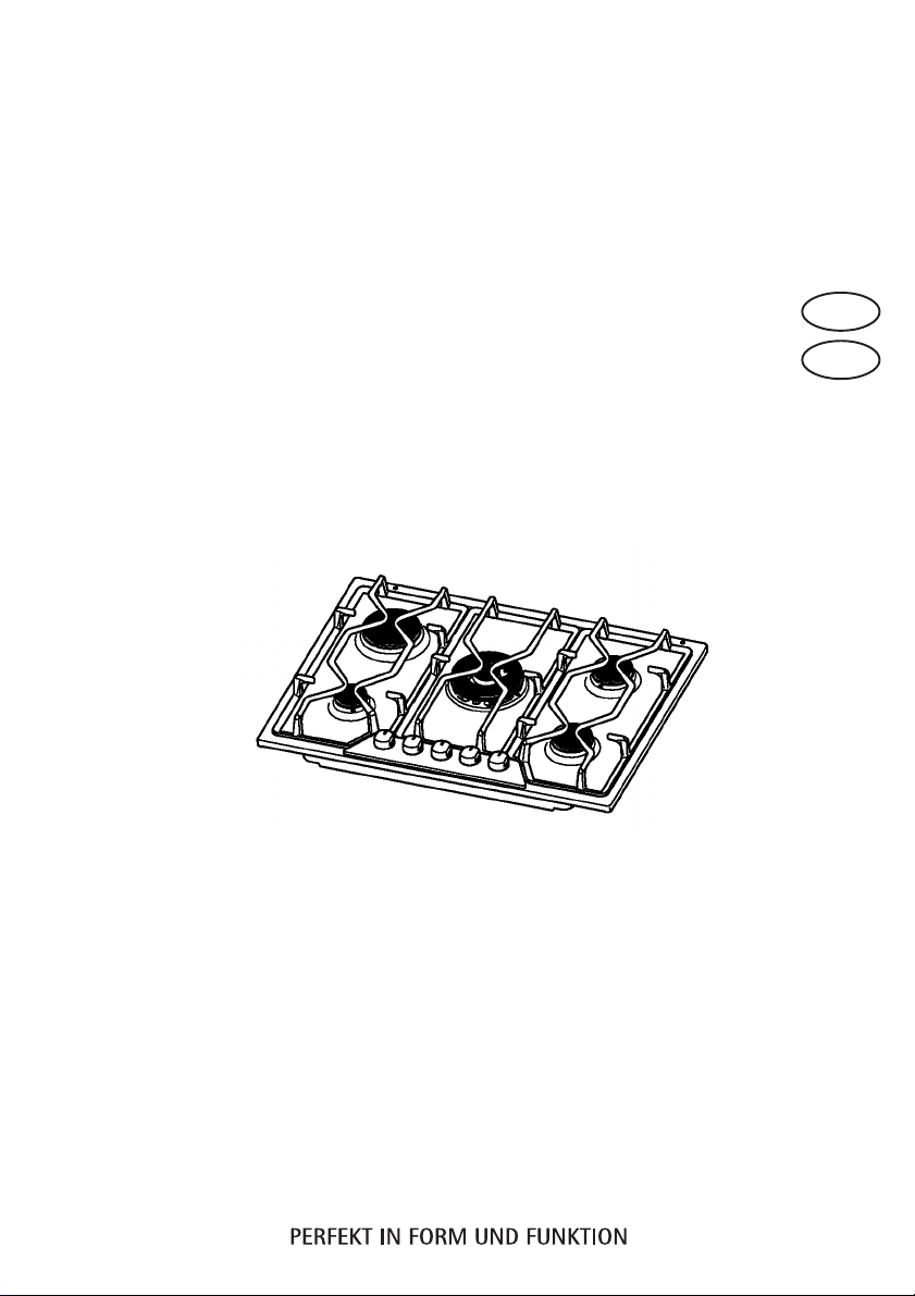
Gas hob
Gazovaå varoqnaå poverxnost¡
Operating and Installation Instructions
Instrukciå po ustanovke i -kspluatacii
CZ
RU
Page 2
ENGLISH
Important Safety Information
These warnings are provided in the interest of safety. You MUST read them
carefully before installing or using the appliance.
Installation
This hob must be installed by qualified personnel, according to the manufacturer’s
instructions and to the relevant Standards in force.
Any gas installation must be carried out by a qualified installer.
Remove all packaging before using the hob.
Ensure that the gas and electrical supply complies with the type stated on the rating plate,
located near the gas supply pipe.
Do not attempt to modify the hob in any way.
Child Safety
CZ
This hob is designed to be operated by adults. Do not allow children to play near or with
The hob gets hot when it is in use. Children should be kept away until it has cooled.
Children can also injure themselves by pulling pans or pots off the hob.
During Use
This hob is intended for domestic cooking only. It is not designed for commercial or
When in use a gas cooking hob will produce heat and moisture in the room in which it
2
the hob.
industrial purposes.
Page 3
has been installed. Ensure there is a continuous air supply, keeping air vents in good
condition or installing a cooker hood with a venting hose.
When using the hob for a long period of time, the ventilation should be improved, by
opening a window or increasing the extractor speed.
Do not use this hob if it is in contact with water. Do not operate the hob with wet hands.
Ensure the control knobs are in the ‘OFF’ position when not in use.
When using other electrical appliances, ensure the cable does not come into contact with
the hot surfaces of the cooking appliance.
Unstable or misshapen pans should not be used on the hob as unstable pans can cause
an accident by tipping or spillage.
Never leave the hob unattended when cooking with oil and fats.
Never use plastic or aluminium foil dishes on the hob.
Perishable food, plastic items and areosols may be affected by heat and should not be
stored above or below the hob unit.
Service
This hob should only be repaired or serviced by an authorised Service Engineer and
only genuine approved spare parts should be used.
Environmental Information
After installation, please dispose of the packaging with due regard to safety and the
environment.
When disposing of an old appliance, make it unusable, by cutting off the cable.
The symbol on the product or on its packaging indicates that this product may not
be treated as household waste. Instead it shall be handed over to the applicable
collection point for the recycling of electrical and electronic equipment. By ensuring this
product is disposed of correctly, you will help prevent potential negative consequences
for the environment and human health, which could otherwise be caused by
inappropriate waste handling of this product. For more detailed information about recycling
of this product, please contact your local city office, your household waste disposal
service or the shop where you purchased the product.
3
Page 4
Contents
For the User
Important Safety Information ...................................................................................... 2
Guide to Use the instructions...................................................................................... 5
Description of the Hob ................................................................................................ 6
Operation .................................................................................................................... 7
Maintenance and Cleaning ......................................................................................... 8
The Hob Top .................................................................................................... 8
Pan Supports ................................................................................................... 8
The Burners ..................................................................................................... 8
Something Not Working? ............................................................................................ 9
For the Installer
Instructions for the Installer....................................................................................... 10
Engineers technical data ............................................................................... 10
Installation ................................................................................................................. 12
Building In ................................................................................................................. 13
Electrical connections ............................................................................................... 17
Adaptation to different types of gas .......................................................................... 18
Injectors replacement .................................................................................... 18
Adjustment of minimum level ........................................................................ 18
4
Page 5
Guide to Use the instructions
The following symbols will be found in the text to guide you throughout the Instructions:
Safety Instructions
Step by step instructions for an
operation
Hints and Tips
Environmental information
This appliance is manufactured according to the following EEC
directives:
73/23 EEC - 90/683 EEC - 93/68 EEC 89/336 EEC - 90/396 EEC,
current edition.
MANUFACTURER:
ELECTROLUX HOME PRODUCTS ITALY S.p.A.
Viale Bologna, 298
47100 FORLÌ (Italy)
Keep this instruction book for future reference and ensure it is passed on to any
new owner.
These instructions are only valid for countries whose identification symbols are
shown on the inside cover of this instruction booklet and on the appliance itself.
5
Page 6
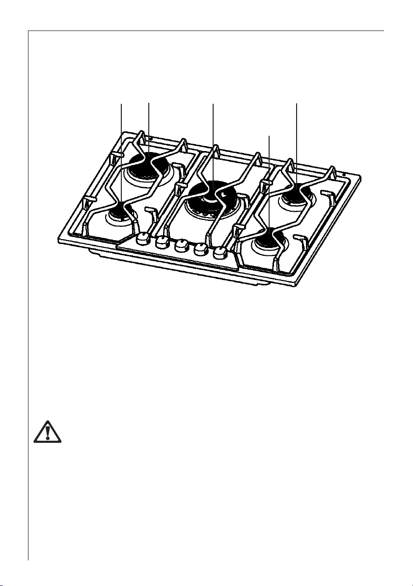
Description of the Hob
4 1
1. Rapid Burner
2. Semi-rapid Burners
3. Triple-crown Burner
4. Auxiliary Burner
3
2
2
Installation
Any gas installation must be carried out by a qualified installer, and in accordance with
existing rules and regulations.
Please, ensure that, once the hob is installed, it is easily accessible for the engineer in
the event of a breakdown.
When the hob is first installed
Once the hob has been installed, it is important to remove any protective materials,
which were put on in the factory.
6
Page 7

Operation
Hob Burners
To light a burner, turn the relevant control knob anticlockwise to the maximum
position ( ), then push it down to ignite the burner.
Upon ignition, keep the knob pushed down for about 5 seconds. This will allow the
"thermocouple" to be heated and the safety device to be switched off, otherwise the
gas supply would be interrupted. Then, check the flame is regular and adjust it as
required.
If the burner does not ignite, turn the control knob to zero, and try again.
When switching on the mains, after installation or a power cut, it is quite normal for the
spark generator to be activated automatically.
To ensure maximum burner efficiency, you should only use pots and pans with a flat
bottom fitting the size of the burner used (see table).
Burner minimum maximum
diameter diameter
Triple-crown 160 mm. 260 mm.
Large (rapid) 160 mm. 240 mm.
Medium (semi-rapid) 120 mm. 220 mm.
Small (Auxiliary) 80 mm. 160 mm.
As soon as a liquid starts boiling, turn down the flame so that it will barely keep the liquid
simmering.
If you use a saucepan which is smaller than the recommended size, the flame will spread
beyond the bottom of the vessel, causing the handle to overheat.
Take care when frying food in hot oil or fat, as the overheated splashes could easily
ignite
If the control knobs become difficult to turn, please contact your local AEG-Electrolux
Service Force Centre.
7
Page 8

Maintenance and Cleaning
Before any maintenance or cleaning can be carried out, you must DISCONNECT the
hob from the electricity supply.
The hob is best cleaned whilst it is still warm, as spillage can be removed more easily
than if it is left to cool.
The Hob Top
Regularly wipe over the hob top using a soft cloth well wrung out in warm water to which
a little washing up liquid has been added. Avoid the use of the following:
- household detergent and bleaches;
- impregnated pads unsuitable for non-stick saucepans;
- steel wool pads;
- bath/sink stain removers.
Pan Supports
When washing the pan supports by hand, take care when drying them as the enamelling
process occasionally leaves rough edges. If necessary, remove stubborn stains using a
paste cleaner.
The Burners
The burner caps and crowns can be removed for cleaning.
Wash the burner caps and crowns using hot soapy water, and remove marks with a mild
paste cleaner. A well moistened soap impregnated steel wool pad can be used with
caution, if the marks are particularly difficult to remove.
After cleaning, be sure to wipe dry with a soft cloth.
8
Page 9

Something Not Working?
If the hob is not working correctly, please carry out the following checks before contacting your
local AEG-Electrolux Service Force Centre.
SYMPTOM
There is no spark when lighting the gas
SOLUTION
Check that the unit is plugged in and the
electrical supply is switched on
Check the mains fuse has not blown
Check the burner cap and crown have
been replaced correctly, e.g. after
cleaning.
The gas ring burns unevenly
Check the main jet is not blocked and the
burner crown is clear of food particles.
Check the burner cap and crown have
been replaced correctly, e.g. after
cleaning.
If after all these checks, your hob still does not operate correctly, contact your local AEG-Electrolux
Service Force Centre.
9
Page 10

Instructions for the Installer
Engineers technical data
OVERALL DIMENSIONS Width: 680 mm.
Depth: 510 mm.
Height: 15 mm.
Weight: 14,5 Kg.
CUT OUT DIMENSIONS Width: 560 mm.
Depth: 480 mm.
Thickness: 30 mm.
HEAT INPUT
Central Burner (triple-crown) 4,0 kW
Rear Left Burner (rapid) 2,8 kW Natural Gas G20 - 20 mbar
2,8 kW L.P.G. G30/G31 28-30/37 mbar
Rear Right Burner (semi rapid) 2,0 kW
Front Right Burner (semi rapid) 2,0 kW
Front Left Burner (auxiliary) 1,0 kW
APPLIANCE CLASS 3
APPLIANCE CATEGORY II2H3+
GAS SUPPLY Natural gas G20 - 20 mbar
10
Page 11

BURNER
Auxiliary
(Small) 1,0 0,33 70 0,095 50 73 71
Ø 55 mm.
Semi-rapid
(Medium) 2,0 0,45 96 0,190 71 145 143
Ø 71 mm.
Rapid Natural Gas:
(Big) 2,8 0,65 113 0,267 86 204 200
Ø 102 mm. LPG: 2,8
TripleCrown 4,0 1,2 146 0,381 98 290 286
Ø 129 mm.
NORMAL REDUCED
POWER POWER
NATURAL GAS LPG GAS
kW kW m3/h g/h
inj.
1/100
NORMAL POWER
20 mbar 28-30/37 mbar
G20
20mbar
inj.
1/100
G30 G31
Burner Dia. Tap By-pass
1/100 mm
Auxiliary 28
Semi-rapid 32
Rapid 40
Triple-Crown 56
Aeration adjustment none
11
Page 12

Installation
The following instructions about installation and maintenance must be carried out by
qualified personnel in compliance with the regulation in force.
The side walls of the unit in which the hob is going to be installed must not exceed
the height of the working top.
Avoid installing the appliance in the proximity of inflammable materials (e.g. curtains,
tea towels etc.).
The appliance must be electrically disconnected before all interventions. If any electric
supply to the appliance is required to carry out the work, ensure all the necessary
precautions are followed.
THE MANUFACTURER WILL NOT ACCEPT LIABILITY, SHOULD ANY OF THE OTHER
SAFETY INSTRUCTIONS INCORPORATED IN THIS BOOK OR THE REGULATION IN
FORCE BE IGNORED.
Gas connection
Choose fixed connections or use a flexible pipe in stainless steel in compliance with the regulation
in force.
If using flexible metallic pipes, be careful they do not come in contact with mobile parts or they are
not squeezed. Use the same attention when the hob is combinated with an oven.
IMPORTANT - To ensure a correct operation, a saving
of energy and the long-life of the appliance, the voltage
pressure of the appliance must correspond to the
recommended values.
The adjustable connection is fixed to the comprehensive
ramp by means of a threaded nut G 1/2".
Interpose the sealing between the components as
shown in Fig. 1.
Screw the parts without forcing, adjust the connection
in the required direction and tighten everything.
IMPORTANT - When the final connection has been
made, it is essential that a thorough leak test is carried
out on the hob and installation. Use some soapy water,
never a flame.
12
FO 0264
A) Ramp with ending nut
B) Seal
C) Adjustable connection
Fig. 1
Page 13

Building In
These hobs can be inserted in a built-in kitchen unit whose depth is between 550 and 600 mm.
The hobs dimensions are shown in Fig. 2.
R
A
UR
680
Fig. 2
A = Auxiliary burner SR = Semi-rapid burner
R = Rapid Burner UR = Triple crown burner
Installation and Assembly
SR
SR
510
These hobs can be installed in a kitchen
unit with an opening for insertion whose
dimensions are shown in Fig. 3.
The edge of the cut out must have a
minimum distance from the rear wall of 55
mm.
If there are side walls, or sides of the
furniture unit near the hob, the cut out
edges must have a minimum distance of
150 mm. as shown in Fig. 3.
Carry out the building in of the hob as
follows:
• put the relevant sealings, supplied with
the hob, on the edges of the cut out: place them exactly on the front and rear edge and at 50
mm. from the side edges, as shown in Fig. 4, taking care that the sealings meet without
overlapping;
FO 2038
Fig. 3
13
Page 14

• place the hob in the cut out, taking care of its
centring;
• fix the hob with the relevant screws (Fig. 5). The
traction of the screws is able to trace the sealing,
any excess of which can then be easily removed.
The edge of the hob forms a double labyrinth
seal which provides a total guarantee against
infiltration of liquids.
FO 2753
FO 0199
a) sealing
Fig. 4
Fig. 5
14
Page 15

Kitchen unit with door
30
20 min
60
a
b
Proper arrangements must be taken in designing the
forniture unit, in order to avoid any contact with the
bottom of the hob which can be heated when it is
operated. The recommended solution is shown in Fig. 6.
The panel fitted under the hob should be easily
removable to allow an easy access if a technical
assistance intervention is needed.
Kitchen unit with oven
The hob recess dimensions must comply the indication
given in Figs. 7 and 8 and must be provided with
brackets to allow a continuous supply of air.
To avoid overhating, the building in should be carried out
as shown in Figs. 9 and 10.
The hob's electric connection and the oven's one must
be carried out separately, both for safety reasons and to
allow the oven to be easily taken off the unit.
Hanging forniture units or hoods must be placed at 650
mm. minimum from the hob.
Fig. 6
FO 2044
a) Removable panel
b) Space possibly useful for
connections
15
Page 16

Fig. 7
Fig. 8
FO 2043
Fig. 9
480
380
140
30
591
50 cm
550 min.
560 min.
FO 0198
Fig. 10
2
120 cm
2
16
FO 2041
360 cm
2
FO 2042
180 cm
2
Page 17

Electrical connections
The appliance is designed to be connected to 230 V monophase electricity supply.
The connection must be carried out in compliance with the laws and regulations in force.
Before the appliance is connected:
1) check that the main fuse and the domestic installation can support the load (see the rating
label);
2) check that the power supply is properly earthed in compliance with the current rules;
3) check the socket or the double pole switch used for the electrical connection can be easily
reached with the appliance built in the forniture unit.
The appliance is supplied with a connection cable. This has to be provided with a proper plug, able
to support the load marked on the identification plate. The plug has to be fitted in a proper socket.
If connecting the appliance directly to the electric system, it is necessary that you install a double
pole switch between the appliance and the electricity supply, with a minimum gap of 3 mm.
between the switch contacts and of a type suitable for the required load in compliance with the
current rules.
The connection cable has to be placed in order that, in each part, it cannot reach a room
temperature higher than 90 °C.
The brown coloured phase cable (fitted in the terminal block contact marked with "L") must always
be connected to the network phase.
Replacement of the voltage cable
The replacement of the voltage cable requires the specific
equipment of a technician.
In this case, only cable type H05 V2V2-F must be used.
The cable section must be suitable to the voltage and the
working temperature.
The yellow/green earth wire must be approximately 2 cm.
longer than the phase wires.
Earth (yellow/green)
Neutral
To open the terminal block and reach the terminals, proceed
as follows:
• insert the point of a screwdriver into the visible protruding
part of the terminal block;
• exert a light pressure and lift. (Fig. 11)
Fig. 11
FO 0257
17
Page 18

Adaptation to different types of gas
Injectors replacement
• Remove the pan supports.
• Remove the burner's caps and crowns.
• With a socket spanner 7 unscrew and remove the
injectors (Fig. 12), and replace them with the ones
required for the type of gas in use (see tables - pag.
11).
• Reassemble the parts, following the same procedure backwards.
• Replace the rating label (placed near the gas
supply pipe) with the relevant one for the new type
of gas supply. You can find this label in the package
of the injectors supplied with the appliance.
Should the feeding gas pressure be different or
variable compared with the required pressure, an
appropriate pressure adjuster must be fitted on the gas
supply pipe, in compliance with the rules in force.
Adjustment of minimum level
FO 0392
Fig. 12
To adjust the minimum level of the burners, proceed as follows:
• Light the burner.
• Turn the knob on the minimum position.
• Remove the knob.
• With a thin screwdriver, adjust the bypass screw (see Fig. 13). If changing
from natural gas to LPG, completely
tighten clockwise the screw, until a small
regular flame is obtained.
• Finally check the flame does not go out
when quickly turning the knob from the
maximum position to the minimum
position.
This procedure can easily be carried out,
anyhow the hob has been positioned or built in the working top.
18
Fig. 13
Adjustment screw
 Loading...