

Page 1
ENGLISH
BE
Important Safety Information
These warnings are provided in the interest of safety. You must read them carefully
before installing or using the appliance.
During Operation
• This appliance has been designed for non professional purpose in private houses only. It is meant
to cook edible foodstuff only and MUST NOT be used for any other purposes.
• It is dangerous to alter the specification in any way.
• For hygiene and safety reasons, this appliance should be kept clean at all times. A build-up of
fats or other foodstuff could result in a fire.
• Under no circumstances should you attempt to repair the appliance yourself. Repairs carried out
by unexperienced persons may cause injury or serious malfunctioning. Refer to your local
Service Centre. Always insist on genuine spare parts.
• Ensure that all control knobs are in the OFF position when not in use.
• Should you connect any electrical tool to a plug near this cooking appliance, ensure that electric
cables are not in contact with it and keep them far enough from the heated parts of this appliance.
• If the appliance is out of order, disconnect it from the electric supply.
Child Safety
• This appliance has been designed to be operated by adults and children under supervision.
Young children MUST NOT be allowed to tamper with the controls or play near or with the oven.
• Accessible parts of this appliance may become hot when it is in use. Children should be KEPT AWAY
until it has cooled.
About Installation, Cleaning and Manteinance
• It is mandatory that all operations required for the installation are carried out by a qualified or
competent person, in accordance with existing rules and regulations.
• Disconnect the appliance from the electrical supply, before carrying out any cleaning or
manteinance work.
• Ensure a good ventilation around the appliance. A poor air supply could cause lack of oxygen.
56
Page 2
• Ensure that the gas supply complies with the gas type stated on the identification label, placed near
the gas supply pipe.
• This appliance is not connected to a combustion products evacuation device. It must be installed
and connected in accordance with current installation regulations. Particular attention shall be
given to the relevant requirements regarding ventilation.
• The use of a gas cooking appliance results in the production of heat and moisture in
the room in which it is installed. Ensure that the kitchen is well ventilated: keep natural
ventilation holes open or install a mechanical ventilation device (mechanical extractor
hood).
• Prolonged intensive use of the appliance may call for additional ventilation, for
example opening of a window, or more effective ventilation, for example increasing
the level of mechanical ventilation where present.
• Once you removed all packaging from the appliance, ensure that it is not damaged and the electric
cable is in perfect conditions. Otherwise, contact your dealer before proceeding with the
installation.
• The manufacturer disclaims any responsability should all the safety measures not be
carried out.
Service
• Under no circumstances should you attempt to repair the appliance yourself. Repairs carried out
by unexperienced persons may cause injury or serious malfunctioning. Refer to your local
Service Centre. Always insist on genuine spare parts.
UU
U
Environmental Information
UU
• After installation, please dispose of the packaging with due regard to safety and the environment.
• When disposing of an old appliance, make it unusable, by cutting off the cable.
• The symbol on the product or on its packaging indicates that this product may not be treated
as household waste. Instead it shall be handed over to the applicable collection point for the
recycling of electrical and electronic equipment. By ensuring this product is disposed of correctly,
you will help prevent potential negative consequences for the environment and human health,
which could otherwise be caused by inappropriate waste handling of this product. For more
detailed information about recycling of this product, please contact your local city office, your
household waste disposal service or the shop where you purchased the product.
These instructions are only for the countries stated by the symbol printed on the
front cover of this instruction book.
57
Page 3
Contents
Important Safety Information.............................................................. 5 6
Guide to Use the instructions ............................................................. 5 9
Description of the Hob.......................................................................... 6 0
Operation.................................................................................................. 6 1
Maintenance and Cleaning ................................................................. 6 2
The Hob Top.................................................................................. 6 2
Pan Supports ................................................................................ 6 2
The Burners................................................................................... 6 2
Something Not Working? .................................................................... 6 3
Instructions for the Installer................................................................. 6 4
Engineers technical data ........................................................... 6 4
Installation ................................................................................................ 6 6
Building In................................................................................................. 6 8
Electrical connections ........................................................................... 7 1
Commissioning ....................................................................................... 7 2
Pressure Testing .......................................................................... 7 2
Conversion from Natural Gas to LPG.............................................. 7 3
Method ............................................................................................ 7 3
58
Page 4
Guide to Use the instructions
The following symbols will be found in the text to guide you throughout the
Instructions:
Safety Instructions
))
)
))
Step by step instructions for an
operation
Hints and Tips
This appliance is manufactured according to
the following EEC directives:
73/23 EEC - 90/683 EEC - 93/68 EEC 89/336 EEC - 90/396 EEC,
current edition.
59
Page 5
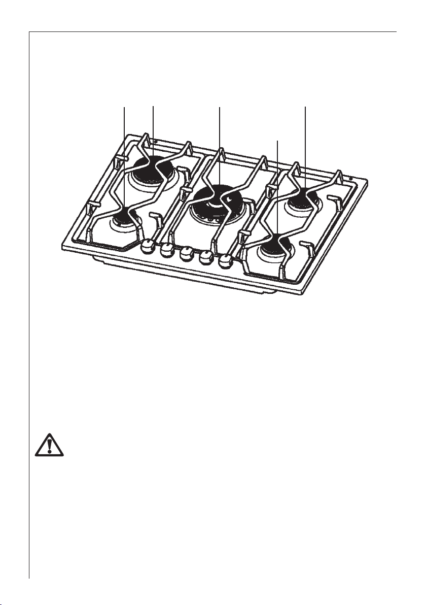
Description of the Hob
4 1
1. Rapid Burner
2. Semi-rapid Burners
3. Triple-crown Burner
4. Auxiliary Burner
3
2
2
60
INSTALLATION
Any gas installation must be carried out by a qualified installer, and in
accordance with existing rules and regulations.
Please, ensure that, once the hob is installed, it is easily accessible for the
engineer in the event of a breakdown.
WHEN THE HOB IS FIRST INSTALLED
Once the hob has been installed, it is important to remove any protective
materials, which were put on in the factory.
Page 6
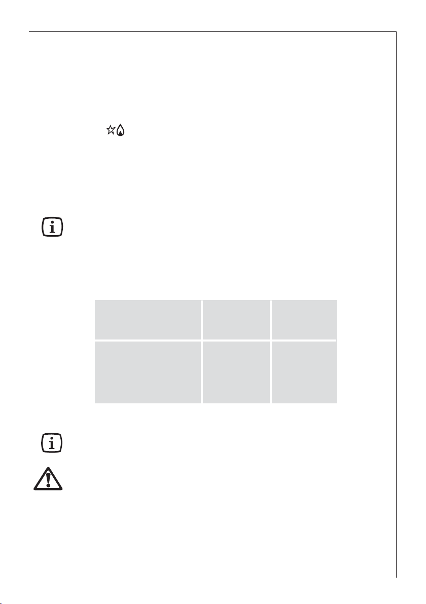
Operation
HOB BURNERS
To light a burner, turn the relevant control knob anticlockwise to the maximum
position (
Upon ignition, keep the knob pushed down for about 5 seconds.
This will allow the "thermocouple" to be heated and the safety
device to be switched off, otherwise the gas supply would be
interrupted. Then, check the flame is regular and adjust it as
required.
If the burner does not ignite, turn the control knob to zero, and try again.
When switching on the mains, after installation or a power cut, it is quite normal
for the spark generator to be activated automatically.
To ensure maximum burner efficiency, you should only use pots and pans
with a flat bottom fitting the size of the burner used (see table).
), then push it down to ignite the burner.
Burner minimum maximum
diameter diameter
Triple-crown 160 mm. 260 mm.
Large (rapid) 160 mm. 240 mm.
Medium (semi-rapid) 120 mm. 220 mm.
Small (Auxiliary) 80 mm. 160 mm.
As soon as a liquid starts boiling, turn down the flame so that it will barely keep
the liquid simmering.
If you use a saucepan which is smaller than the recommended size, the flame
will spread beyond the bottom of the vessel, causing the handle to overheat.
Take care when frying food in hot oil or fat, as the overheated splashes could
easily ignite
If the control knobs become difficult to turn, please contact your local AEGElectrolux Service Force Centre.
61
Page 7
Maintenance and Cleaning
Before any maintenance or cleaning can be carried out, you must
DISCONNECT the hob from the electricity supply.
The hob is best cleaned whilst it is still warm, as spillage can be removed
more easily than if it is left to cool.
The Hob Top
Regularly wipe over the hob top using a soft cloth well wrung out in warm
water to which a little washing up liquid has been added. Avoid the use of the
following:
- household detergent and bleaches;
- impregnated pads unsuitable for non-stick saucepans;
- steel wool pads;
- bath/sink stain removers.
Pan Supports
When washing the pan supports by hand, take care when drying them as the
enamelling process occasionally leaves rough edges. If necessary, remove
stubborn stains using a paste cleaner.
The Burners
The burner caps and crowns can be removed for cleaning.
Wash the burner caps and crowns using hot soapy water, and remove marks
with a mild paste cleaner. A well moistened soap impregnated steel wool pad
can be used with caution, if the marks are particularly difficult to remove.
After cleaning, be sure to wipe dry with a soft cloth.
62
Page 8

Something Not Working?
If the hob is not working correctly, please carry out the following checks before
contacting your local AEG-Electrolux Service Force Centre.
SYMPTOM
There is no spark when lighting
the gas
SOLUTION
Check that the unit is plugged in
and the electrical supply is
switched on
Check that the RCCB has not
tripped (if fitted)
Check the mains fuse has not
blown
Check the burner cap and crown
have been replaced correctly, e.g.
after cleaning.
The gas ring burns unevenly
Check the main jet is not blocked
and the burner crown is clear of
food particles.
Check the burner cap and crown
have been replaced correctly, e.g.
after cleaning.
If after all these checks, your hob still does not operate correctly, contact
your local AEG-Electrolux Service Force Centre.
63
Page 9

Instructions for the Installer
Engineers technical data
OVERALL DIMENSIONS Width: 680 mm.
Depth: 510 mm.
Height: 15 mm.
CUT OUT DIMENSIONS Width: 560 mm.
Depth: 480 mm.
Thickness: 30 mm.
HEAT INPUT
Central Burner (triple-crown) 4,0 kW
Rear Left Burner (rapid) 2,8 kW Natural Gas
2,8 kW L.P.G.
Rear Right Burner (semi rapid) 2,0 kW
Front Right Burner
Front Left Burner (auxiliary) 1,0 kW
APPLIANCE CLASS 3
APPLIANCE CATEGORY II2E+3+
GAS SUPPLY Natural gas G20/G25 - 20/25mbar
64
(semi rapid) 2,0 kW
Page 10

BURNER
NORMAL REDUCED
POWER POWER
NORMAL POWER
NATURAL GAS
kW kW m3/h g/h
inj.
1/100
Auxiliary
(Small) 1,0 0,33 70 0,095 0,111 50 73 71
Ø 55 mm.
Semi-rapid
(Medium) 2,0 0,45 96 0,190 0,221 71 145 143
Ø 71 mm.
Rapid Natural Gas:
(Big) 2,8 0,65 113 0,267 0,310 86 204 200
Ø 102 mm. LPG:2,8
TripleCrown 4,0 1,2 146 0,381 0,443 98 291 286
Ø 129 mm.
G20 G25
20mbar 25mbar
LPG GAS
28-30/37 mbar
inj.
1/100
G30 G31
Burner Dia. Tap By-pass
1/100 mm
Auxiliary 28
Semi-rapid 32
Rapid 40
Triple-Crown 56
Aeration adjustment none
65
Page 11

Installation
zz
z The side walls of the unit in which the hob is going to be installed,
zz
must not exceed the height of the working top.
zz
z Avoid installing the appliance in the proximity of inflammable
zz
materials (e.g. curtains, tea towels etc.).
zz
z The following instructions about installation and maintenance
zz
must be carried out by qualified personnel in compliance with
the regulation in force. The regulation to be applied for this type
of installation is NBN D 5I.003 : "Installations functioning with
combustible gas lighter than air".
zz
z The appliance must be electrically disconnected before all
zz
interventions. If any electric supply to the appliance is required
to carry out the work, ensure all the necessary precautions are
followed.
GAS CONNECTION
It is indispensible that the connection to the gas mains are carried out by
means of an AGB tap. Choose fixed connections or use a flexible pipe
in AGB (stainless steel).
If using flexible metallic pipes, be careful they do not come in contact with
mobile parts or they are not squeezed. Use the same attention when the
hob is combinated with an oven.
This hob can be operated by Slochteren gas (G25) with a nominal
pressure of 25 mbar or by natural gas with nominal pressure of 20 mbar.
No regulation is required for use by these two types of gas.
Before fitting the appliance ensure that the installation has the correct
voltage for the appliance. At full capacity, the drop in pressure must not
exceed 5%. Such a drop in pressure is caused by the following parameters:
- maximum capacity of meter;
- diameter and lenght of the tube in front and behind the meter;
- section of transit of variuos tubes positioned on the circuit;
- diameter of eventual connections.
66
Page 12

IMPORTANT - To ensure a correct operation, a saving of energy and
the long-life of the appliance, the voltage pressure of the appliance must
correspond to the recommended values.
The adjustable connection is fixed to the comprehensive ramp by means
of a threaded nut G 1/2".
All the components shown in the diagramm have already been assembled
in the factory.
The appliance, before leaving the factory, has been tested in order to
give you the best results.
IMPORTANT - When the final connection has been made, it is essential
that a thorough leak test is carried out on the hob and installation. Use
some soapy water, never a flame.
FO 2365
A) Ramp with ending nut
B) Seal
C) Adjustable connection
67
Page 13

Building In
These hobs can be inserted in a built-in kitchen unit whose depth is between 550
and 600 mm. The hobs dimensions are shown in Fig. 1.
R
A
UR
680
Fig. 1
A = Auxiliary burner SR = Semi-rapid burner
R = Rapid Burner UR = Triple crown burner
Installation and Assembly
SR
SR
510
These hobs can be installed in a
kitchen unit with an opening for
insertion whose dimensions are
shown in Fig. 2.
The edge of the cut out must have a
minimum distance from the rear wall
of 55 mm.
If there are side walls, or sides of the
furniture unit near the hob, the cut out
edges must have a minimum
distance of 150 mm. as shown in Fig.
2.
Carry out the building in of the hob as
follows:
• put the relevant sealings, supplied with the hob, on the edges of the cut out: place
them exactly on the front and rear edge and at 50 mm. from the side edges, as shown
in Fig. 3, taking care that the sealings meet without overlapping;
68
FO 2038
Fig. 2
Page 14

• place the hob in the cut out, taking care
30
20 min
60
a
b
of its centring;
• fix the hob with the relevant screws (Fig.
4). The traction of the screws is able to
trace the sealing, any excess of which
can then be easily removed.
The edge of the hob forms a double
labyrinth seal which provides a total
guarantee against infiltration of liquids.
Kitchen unit with door
Proper arrangements must be taken in designing the forniture unit, in order to avoid
any contact with the bottom of the hob which can be heated when it is operated.
The recommended solution is shown in Fig. 5.
The panel fitted under the hob should be easily
removable to allow an easy access if a technical
assistance intervention is needed.
FO 2753
FO 0199
a) sealing
Fig. 3
Fig. 4
Fig. 5
Kitchen unit with oven
The hob recess dimensions must comply the
indication given in Figs. 6 and 9 and must be
provided with brackets to allow a continuous
supply of air.
To avoid overhating, the building in should be
carried out as shown in Figs. 7 and 8.
The hob's electric connection and the oven's one
must be carried out separately, both for safety
reasons and to allow the oven to be easily taken off
the unit.
Hanging forniture units or hoods must be placed at
650 mm. minimum from the hob (Fig. 9).
FO 2044
Fig. 5
a) Removable panel
b) Space possibly useful for
connections
69
Page 15

2
550 min.
480
Fig. 6
380
140
Fig. 7
30
591
560 min.
FO 2043
Fig. 8
FO 2041
50 cm
360 cm
FO 0198
Fig. 9
2
2
FO 2042
120 cm
180 cm
2
70
Page 16

Electrical connections
The appliance is designed to be connected to 230 V monophase
electricity supply.
The connection must be carried out in compliance with the laws and
regulations in force.
Before the appliance is connected:
1) check that the main fuse and the domestic installation can support
the load (see the rating label);
2 ) check that the power supply is properly earthed in compliance with
the current rules;
3) check the socket or the double pole switch used for the electrical
connection can be easily reached with the appliance built in the
forniture unit.
The appliance is supplied with a connection cable. This has to be
provided with a proper plug, able to support the load marked on the
identification plate. The plug has to be fitted in a proper socket.
If connecting the appliance directly to the electric system, it is necessary
that you install a double pole switch between the appliance and the
electricity supply, with a minimum gap of 3 mm. between the switch
contacts and of a type suitable for the required load in compliance with
the current rules.
The connection cable has to be placed in order that, in each part, it
cannot reach a room temperature higher than 50 °C.
The brown coloured phase cable (fitted in the terminal block contact
marked with "L") must always be connected
to the network phase.
REPLACEMENT OF THE VOLTAGE CABLE
The replacement of the voltage cable
requires the specific equipment of a
technician.
In this case, only cable type H05 V2V2-F
must be used. The cable section must be
suitable to the voltage and the working
temperature.
The yellow/green earth wire must be
approximately 2 cm. longer than the phase
wires.
Neutral
Earth (yellow/green)
71
Page 17

Commissioning
When the hob has been fully installed it will be necessary to check the minimum
flame setting. To do this, follow the procedure below.
1) Turn the gas tap to the MAX position and ignite.
))
)
))
2) Set the gas tap to the MIN flame position then turn the control knob from
MIN to MAX several times. If the flame is unstable or is extinguished follow
the procedure below.
Procedure:
1) Re-ignite the burner and set
))
)
))
to MIN.
2) Remove the control knob.
3) To adjust, use a thin bladed
screwdriver and turn the
adjustment screw until the
flame is steady and does
not extinguish, when the
knob is turned from MIN to
MAX. Repeat this
procedure for all burners.
Adjustment screw
Pressure Testing
1) Remove left hand pan support and front left burner cap and crown.
))
)
))
2) Fit manometer tube over the injector.
3) Turn on the burner gas supply and ignite another burner supply.
The pressure reading should be nominally 20mbar and must be between
17 mbar and 25mbar.
4) Turn off the burner supplies.
72
Page 18

Conversion from Natural Gas to LPG
It is important to note that this model is designed for use with natural gas but can be
converted for use with butane or propane gas providing the correct injectors are fitted
and the gas rate is adjusted to suit.
Method
1) Ensure that the gas taps are in the 'OFF' position
))
)
))
2) Isolate the hob from the electricity supply
3) Remove all pan supports, burner caps, rings, crowns and control knobs.
4) With the aid of a 7mm box spanner the burner injectors can then be
unscrewed and replaced by the appropriate LPG injectors.
TO ADJUST THE GAS RATE
With the aid of a thin bladed screwdriver completely tighten down the by pass
adjustment screw, which is located down the centre of the gas tap control
shaft. Upon completion stick the replacement rating plate on the under side of
the hob.
IMPORTANT
The replacement/conversion of the gas hob should only be undertaken
by a competent person.
73
Page 19

74
Page 20

75
Page 21

AEG Hausgeräte GmbH
Postfach 1036
D-90327 Nürnberg
http://www.aeg.hausgeraete.de
Copyright by AEG
From the Electrolux Group. The world’s No.1 choice.
The Electrolux Group is the world’s largest producer of powered appliances for kitchen, cleaning
and outdoor use. More than 55 million Electrolux Group products (such as refrigerators, cookers,
washing machines, vacuum cleaners, chain saws and lawn mowers) are sold each year to a value
of approx. USD 14 billion in more than 150 countries around the world.
35688-9501 01/05
Grafiche MDM - Forlì
 Loading...