

Page 1
INSTRUCTION BOOK
GB
353 WK-m ZA 949600806
1
Page 2
Congratulations from AEG
Dear Customer,
Congratulations with your new Hob.
It is important that you become familiar with the functions and features of
the Hob. You should therefore read these operating instructions as they will
help you get the most out of your new Hob.
Pay extra attention to sections marked . These are warning texts to help
you avoid accidents.
Keep the operating instructions. They will come in handy if there is
something you are not sure about, and should accompany the Hob if it is
transferred to a new owner.
The structure of the operating instructions enables you to use them as a
reference manual. The first part of the operating instructions contains a
general description of your new product. Then follows a short introduction
of the things to do before you use the Hob for the first time. The section
“How to use” describes how the Hob is used in everyday life. Use this
section until you are familiar with your new Hob. The section “Cleaning
and Maintenance” provides information on both daily and more thorough
cleaning of the individual components of the Hob. Should problems arise
when you use the Hob, you can look in the section “Before calling service”,
where there are instructions on how to remedy some practical and technical
problems yourself.
Enjoy!
Regards,
2
Page 3
Table of contents
Contents Page no
For the user
Your new appliance ...................................................................................... 2
Safety information ........................................................................................ 4
Description of the product ......................................................................... 5
Placement of grid ................................................................................. 5
Operating instructions ................................................................................ 6
Burner cover/inner- and outer burner ring ............................................ 7
Ignition electrode (A) ........................................................................... 7
Thermo Sensor (B) ............................................................................... 7
Ignitions .................................................................................................. 10
Cleaning and maintenance of ................................................................... 11
Panel .................................................................................................. 11
Stainless steel surfaces ....................................................................... 12
The wok .............................................................................................. 12
Service .................................................................................................. 20
Service and spareparts ....................................................................... 21
Guarantee conditions ................................................................................ 22
For the installer
Mounting .................................................................................................. 13
Technical data ............................................................................................. 19
How to read the operating instructions:
1... 2...Step by step
Safety information
3
Hint and tips
Environmental information
Page 4
Safety information
These warnings are provided in the
interests of your safety. Ensure you
fully understand them before installing
or using the appliance. Your safety is of
paramount importance. If you are
unsure about the meaning of these
warnings contact the Customer Care
Department for assistance.
Installing
This wok must be installed according
to the instructions supplied. Any
installation work must be undertaken
by a qualified competent person.
Do not alter the specifications or
attempt to modify the appliance in any
way.
During Use
The wok is intended for domestic
cooking only. It is not designed for
commercial/industrial purposes.
Ensure that the control knob is in the
OFF position when not in use.
Do not use the wok if it is damaged in
any way, contact your local AEG
Service Centre.
Child Safety
Young children must not be allowed to
tamper with the wok or play with the
control.
The wok gets hot when it is in use.
Children should be kept away until the
wok has cooled.
Maintenance and Cleaning
Only clean this wok in accordance
with the instructions given in this
book.
Service
Repairs carried out by inexperienced
persons may cause injury or serious
malfunction of the appliance. Repairs
must only be carried out by a
qualified/competent person. Contact
your local AEG Service Centre.
Disposal
Make the wok unusable by cutting off
the cable.
Dispose of any packaging material and
old appliances at an authorised
disposal site.
Never use plastic or aluminium dishes
on the wok.
Never leave the wok unattended while
deep fat frying, or heating fats and oils.
4
Page 5

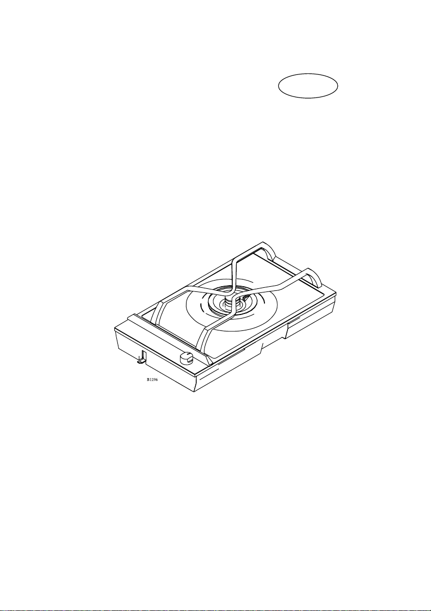
Description of the product
Burner
Knob
Placement of grid
Guide knop for grid
5
Page 6
Operatings instructions
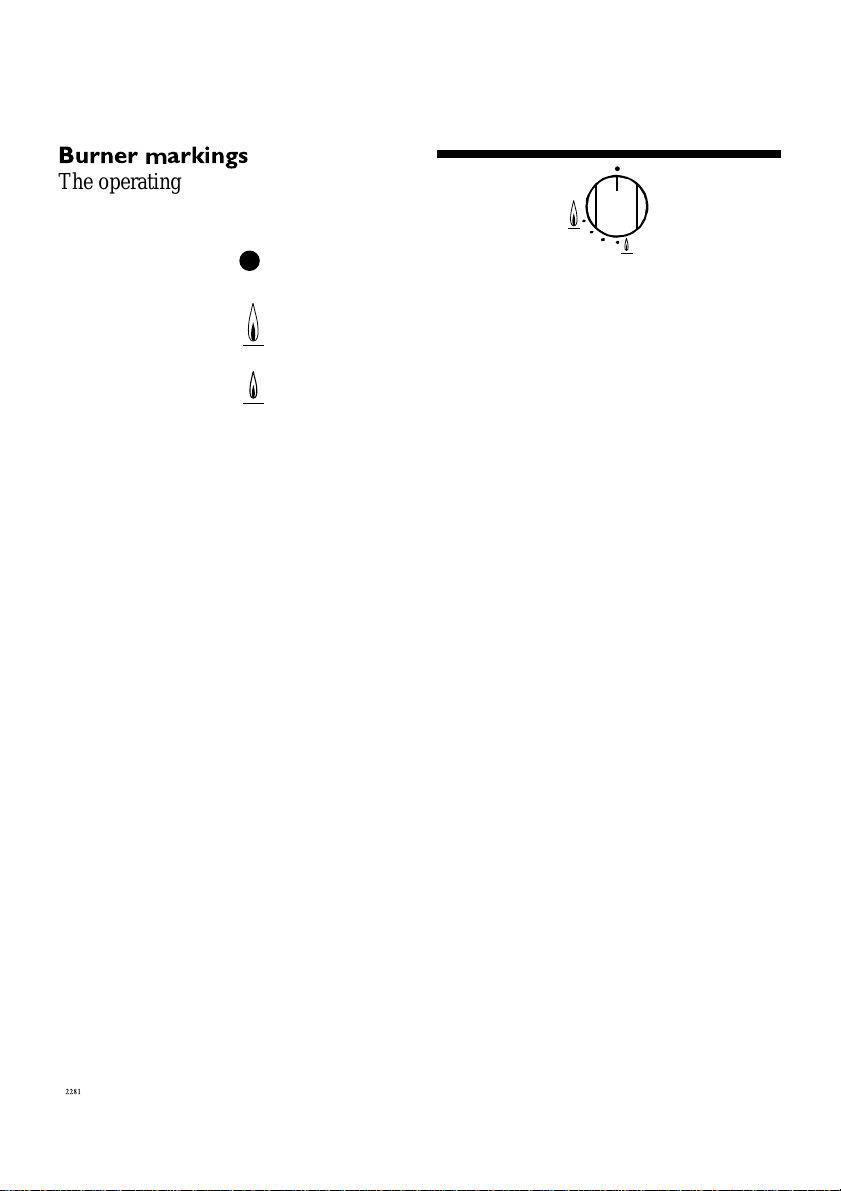
Burner markings
The operating knob has a ring showing
the scale of markings.
Off.
Max. flame
and ignition position
Min. flame
6
Page 7
Burner cover/inner burner
ring/outer burner ring
Together with the inner burner ring the
outer burner ring forms a space where the
final mixture of gas and air takes place in
order to make the gas burn correctly.
Please note: It is consequently very
important that the inner burner ring/outer
burner ring is placed correctly, together
with the cover.
If the burner cover/rings are wrongly
placed the burner will operate incorrectly,
and the burner may be damaged within a
short space of time. It is also important,
that the inner air ring is placed correctly.
Ignition electrode (A)
The burner has been provided with an
ignition electrode. As long as the
operating knob is depressed, the
automatic ignition will ensure that a
spark is emitted between the ignition
electrode and the burner cover.
Cover
Ignition electrode (A)
Burner Main nozzle
Burner ring
Thermo Sensor (B)
The gas unit features fully-secured gas
taps (thermo-fuse)
In case the flame goes out, the thermo
sensor automatically prevents gas
admission after a shorter time (Max. 90
seconds).
Note: Gas admission is always allowed
while the operation button is pressed See start-up procedure
Thermo Sensor (B)
7
Page 8

Outer burnerring
Cover
Inner burnering
Air valve
Burner body
8
Page 9

Please note: If the wok is mounted in a
table top with a cupboard underneath,
the flame might be blown out if the
door is slammed.
The wok-unit has a special pan support
which enables use of a wok pot with
curved bottom.
When using cooking utensils with a
flat bottom the diameter of the utensils
must not be less than 26 cm.
9
Page 10

Ignitions
1. Depress and turn the control knob
for the burner, the left to Max. flame
2. The ignition electrode will emit
sparks, and when the mixture of gas
and air is correct, the burner will be
ignited. Is not possible to connect
the unit to mains, a match may be
used to ignite the burner
3. After starting the burner, press the
control knob for approx. 10
seconds to activate the automatic
thermo couple.
4. Important Ignition position is at
Max flame
10
Page 11

Cleaning and maintenance of
For reasons of hygiene and
safety, the cooking burner
must be kept clean.
Grease stains and spilled
food generate smoke when
heated, and can even cause
fire.
Splashguard
The splashguard can be removed to
make it easier to clean the surface.
What to do:
1. Hold the splashguard as shown
in the diagram.
2. Lift the splashguard straight up
3. Clean the top surface as
described in “cleaning the steel
surface”.
Be aware of the two retaining
pegs, which are sharp.
4. Replace the splashguard in
position ENSURE that it is
fitted the correct way round.
Never use hard or sharp
implements to lift off the
splashguard.
Do not wash the splashguard
in a dishwasher.
The hob must not be used
with the splashguard off.
11
Page 12

Stainless steel surfaces
Perform daily cleaning with a slightly
damp cloth. For more severe soiling,
use a liquid cream. Always clean the
steel in the direction of the steel finish.
To ensure that the steel retains its
shine, it is recommended that you use
a polishing agent for stainless steel on
a regular basis. Always polish in the
direction of the steel finish (crosswise).
Never use steel wool, metal sponges or
other abrasive cleaning agents.
The wok
The operating panel with knob, pan
support, top plate and burner
covers/rings are to be cleaned with
ordinary cleaning agents.
However, do not use any kind of
scouring powder.
Avoid saucepans boiling over. If you
have been so unfortunate as to get
water in the burner this water should
be removed before reigniting the
burner, e.g. with a no-fluff cloth.
12
Page 13

Mounting
Caution: In order to avoid a hazard this
appliance must be installed according to
these instructions for installation
The hob unit can be mounted in any
type of kitchen with a table surface
whose thickness is between 28 mm and
40 mm.
Headroom
The distance to any shelves or tops of a
cabinet under the hob is to be at least 47
mm.
Fixing
Screw the fixing brackets out to such an
extent that they can be turned in under
the table top. Tighten the brackets on to
the table top with an ordinary
screwdriver.
Minimum distance
to wall:
150 mm
Reinforcement
beams
Minimum distance to
wall (non flammable
material): 50 mm
Cut-out measurements
One rectangular hole is sawn out for the
hob combination chosen.
The depth of the cut-out for any unit is:
490 mm
Length of hole = sum of all units`
externally measured length, less 20 mm.
Mounting of Reinforcement
Beams
A reinforcement Beam, with supporting
flanges at each end, is included with
each two-burner unit. For unit
combinations, a reinforcement beam
must be used between each unit.
13
Page 14

It is not necessary to attach the
reinforcement beam to the work top
surface, as it is held in place by a
specially designed moulding, which is
incorporated in the hob units flanges.
The units externally measured
length
145 mm:
Cooker hood
290 mm:
Two-zone ceramic-top electric hob
Two-burner gas hob
Grill
Fryer
Wok
580 mm:
Four-zone ceramic-top electric hob
Four-burner gas hob
725 mm:
Four-zone ceramic-top electric hob
Installation of a single unit
When mounting a single unit, be it a
half-or full size unit, in a
worktopsurface which is thicker than
30 mm, it is necessary to make a
special notch in both sides of the cutout hole, as shown in the adjacent
drawing.
The purpose of these notches is to
create space for the electrical cables.
14
Page 15

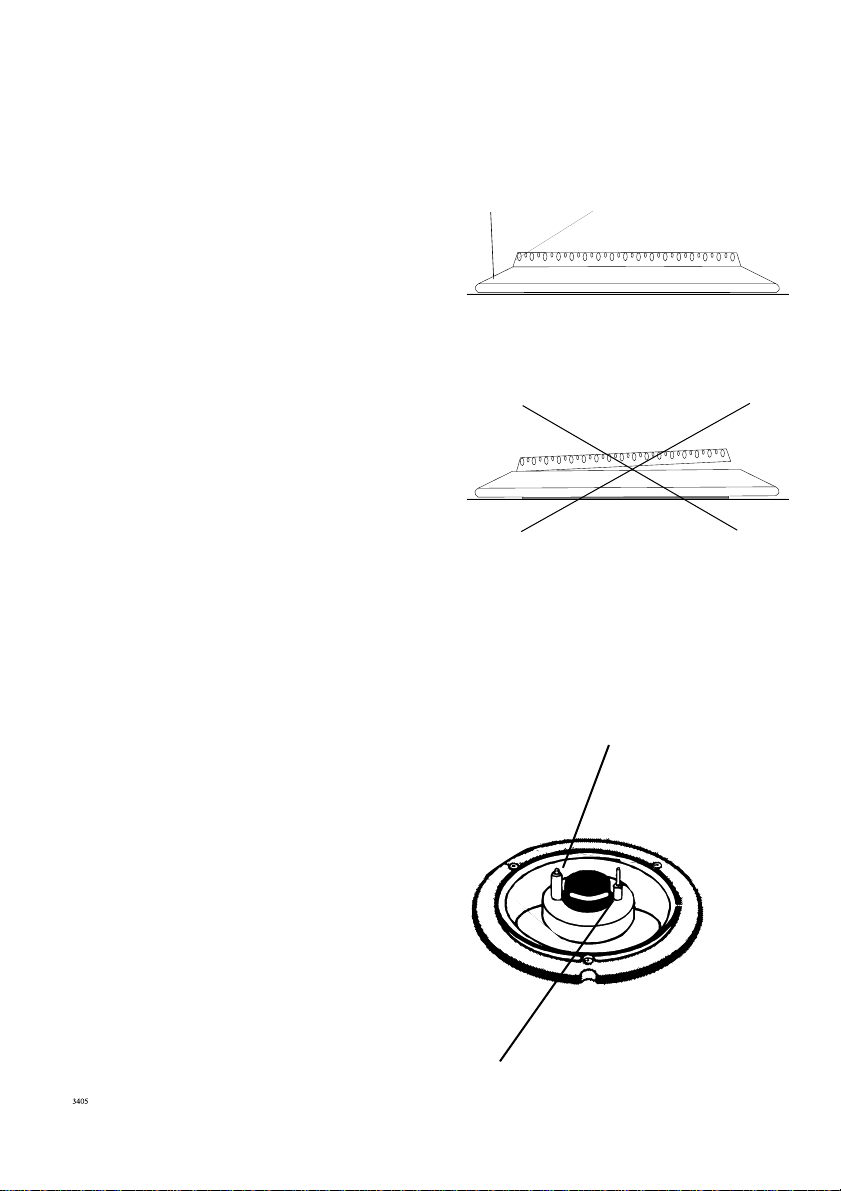
Installation of wok burner
It is extremely important that
both the inner and outer
burner rings are fitted
correctly into their “guide
notch”, otherwise the burner
will burn with an incorrect
flame pattern and could be
ruined within a very short
period. You must be able to
hear a click telling you that
the rings have been correctly
fitted.
How to proceed:
1. Fit the air valve in the burner
body. See fig. 1
Air valve
Fig. 1
Inner burner ring
2. Then fit the inner burner ring,
taking care that the guide pin
engages in the notch. See fig. 2.
Fig. 2
15
Page 16

3. Place the cover plate over. See
fig. 3.
Fig. 3
Cover plate
4. Finally, fit the outer burner ring,
taking care that the guide pin
engages in the notch. See fig. 4.
Fig. 4
Outer burner ring
16
Page 17

Gas installation
In accordance with local
requirements for domestic gas
cooking appliances.
Gas installation must only be
carried out by an authorised person.
For gas types see technical data.
Gas connection
The gas intake is situated at the
lower rear of the appliance. The
intake has a ½" conical pipe thread
(see fig 1) If the appliance is to be
connected to a gas cylinder,
conversion with the optional
modification kit will be necessary.
Pressure test
The unit should be pressure-tested
at Max. 150 mbar.
17
Page 18

An opening with a minimum area of 60
cm2 must be present at the back of the
cupboard (see fig.).
18
Page 19

Technical data
Type of gas
Adjusted for: Natural, G-20 - 20mbar
Category and pressures
ZA: II2E3B/P 20-50 mbar
Max. nominal load Q, HS:
Wok burner = 5,0 kW x 1
Total= 5,0 kW
Convertible to bottledgas - G30-50 mbar
FSD
The unit features fully-secured gas taps
(thermo-fuse).
HS = Gross calorific value
Q = Nominal load
Voltage= 220-240 V AC
Ignition transformer= 50 HZ - 0,6 VA
230 V
1N + PE
N L1
The Dropinett must be connected via
an external switch with a contact
gap of min. 3 mm (the main switch
may be used)
Cable type: 0,75 mm² HO5VV-F
CE 048 AT- 0030
Radio-noise reduction
This unit observes the current EEC-directive
on radio noise reduction.
This gas appliance is -approved and marked in accordance with the gas appliance
Directive (90/396/CEE), the low voltage
directive (73/23/CEE) and the EMC directive
(89/336/CEE incl. the agreed directive
changes.
19
Page 20

Service
Question:
There is no spark when lighting the
gas?
When the operating knob is released
the gas ring goes out again?
The gas ring burns very unevenly??
Answer
Check whether the 230 V connection
has been plugged in. The ground fault
circuit relay way have switched off.
The fuse has blown
The operating knob has not been
depressed long enough, or has not
been depressed sufficiently.
Check whether the cover has been
replaced correctly, e.g. after cleaning.
20
Page 21

24
325 88-1657 Rev. 3-021
 Loading...