

Page 1
HG60FXA
HG75FXA
HG90FXA
EN User manual
Page 2

Page 3

GENERAL NOTICE
We invite you to read this instruction booklet carefully, before installing and using the equipment.
It is very important that you keep this booklet together with the equipment for any future
If this equipment should be sold or transferred to another person, make sure that the new
user receives the booklet, so that they can learn how to operate the appliance and read the
This appliance complies with the following Directives:
EEC 2009/142/CE (Gas) EEC 2004/108/CE (Electromagnetic Compatibility)
EEC 2006/95/CE (Low Voltage) EEC 2004/1935/CE (Contact with foods)
WARNING
– The installation must be carried out by authorised personnel, in conformity with the regulations in force.
– CAUTION: The surface temperature of underbench components exceeds 95°C. To avoid a hazard,
underbench access must be restricted. Refer to the installation instructions.
– This appliance is not intended for use by persons (including children) with reduced physical, sensory or
mental capabilities, or lack of experience and knowledge, unless they have been given supervision or
instruction concerning use of the appliance by a person responsible for their safety.
– Children should be supervised to ensure that they do not play with the appliance.
– Before powering the equipment, check that it is properly adjusted for the type of gas at disposal (see the
“installation” paragraph).
– If the supply cord is damaged it must be replaced by a special cord or assembly available from the
manufacturer or its service agent.
– Before carrying out the maintenance or cleaning the equipment, cut off power supply and allow it cool
down.
– Make sure that air circulates around the gas equipment. Insufficient ventilation produces a lack of oxygen.
– In case of an intense or prolonged use of the equipment, it may be necessary to improve aeration, for
example by opening a window or increasing rangehood venting power, if it exists.
– The products of combustion must be discharged outside through a suction hood or an electric fan (see
the “installation” paragraph).
– For any possible operation or modification, apply to an authorized Technical Assistance Centre and
demand original spare parts.
– Where this appliance is installed in marine craft or in caravans, it shall not be used as a space heater.
– Not for use in marine craft, caravans or mobile homes unless each burner is fitted with a flame safeguard.
– Do not spray aerosols in the vicinity of the appliance while it is in operation.
– Do not store or use flammable materials or items in the vicinity of this appliance.
consultation.
corresponding notice.
This is a Class 3 appliance.
DO NOT MODIFY THIS APPLIANCE.
Servicing shall be carried out only by authorised personnel.
The product label, with the serial number, is fixed to the underside of hob.
An additional label should be adhered to adjacent cabinetry for easy access- refer installation
instructions.
The manufacturer refuses all responsibility for possible damages to things or people, resulting
from incorrect installation or from an improper, incorrect or unreasonable use of this equipment.
3
Page 4
INSTRUCTIONS FOR THE USER
It is necessary that all the operations regarding the installation, adjustment and
adaptation to the type of gas available are carried out by authorised personnel, in
conformity with the regulations in force. The specific instructions are described in the
booklet section intended for the installer.
Conditions of Use.
This appliance is intended to be used in household and similar applications such as:
- Staff kitchen areas in shops, ofces and other working environments
- Farm Houses
- By clients in hotels, motels and other residential type environments
- Bed and breakfast type environment
USING THE BURNERS
The symbols silk-screen printed on the side of the knob
indicate the correspondence between the knob and the
burner.
Automatic start-up with valves
Turn the corresponding knob anticlockwise up to the
maximum position (large flame, fig.1/1/A) and press the
knob.
Once the burner has been started up, keep the knob
pressed for about 6 seconds.
ATTENTION: the triple ring (wok) burner switches on
only in the maximum flame position
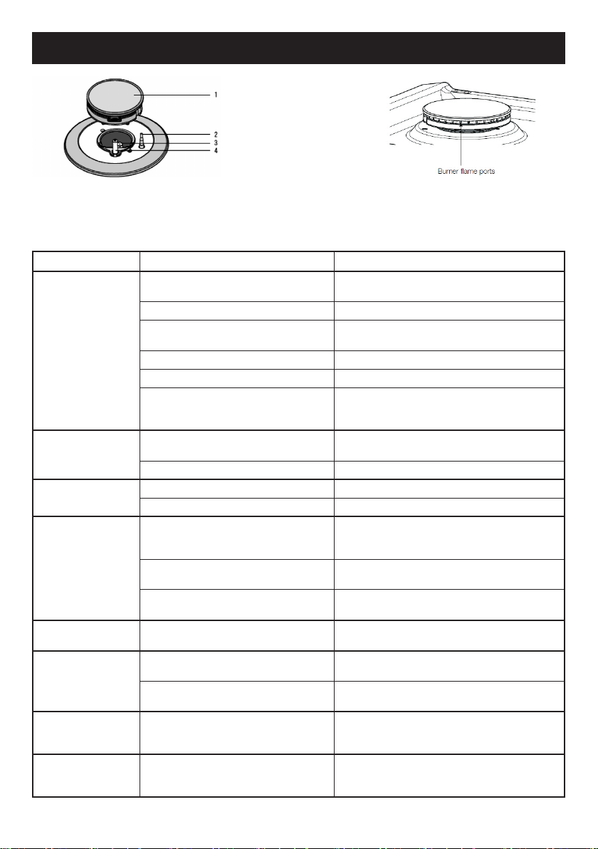
Using the burners
In order to obtain the maximum yield without waste of
gas, it is important that the diameter of the pot is suitable
for the burner potential (see the following table), so as to
avoid that the flame going out (fig. 2).
Use the maximum capacity to quickly make liquids reach
boiling temperature, and the reduced capacity to heat
food or maintain boiling. All of the operating positions
must be chosen between the maximum and the minimum
ones, never between the minimum position and the
closing point.
The gas supply can be interrupted by turning the knob
clockwise up to the closing position. If there is no power
supply, it is possible to light the burners with matches,
setting the knob to the start-up point (large flame, fig. 1).
Power (MJ/h) Ø of
BURNERS
Auxiliary 3,4 3,4 10 - 14 cm
Semi-rapid 6,3 5,6 16 - 18 cm
Triple crown
(wok on 5
burner models)
Double crown
(wok on 4
burner models)
NG LPG
18,0 15,0 24 - 26 cm
10,3 9,6 20 - 22 cm
cookware
(*)
It is important to use cookware with the sizes
specified and ensure the cookware is always
correctly centred over the burner. Using
oversize cookware can potentially cause heat
damage to your benchtop and/or control knobs
which will not be covered under warranty.
Notice
– When the equipment is not working, always check that
the knobs are in the closing position (see fig.1).
– If the flame should blow out accidentally, the safety
valve will automatically stop the gas supply, after a
few seconds. To restore operation, set the knob to the
lighting point (large flame, fig. 1) and press.
– While cooking with fat or oil, pay the utmost attention as
these substances can catch fire when overheated.
– Do not place unstable or deformed pots on the burner,
so as to prevent them from overturning or overflowing.
– Handles should be turned away from the front of the
bench to avoid accidents.
– When the burner is started up, check that the flame is
regular and, before taking pots away, always lower the
flame or put it out.
(*) For cookware with diameter 120mm or
below use mini-trivet supplied, refer fitment
instructions on page 15.
4
Page 5
INSTRUCTIONS FOR THE USER
1 Burner 3 Injector
2 Flame safeguard sensor 4 Ignition spark plug
If you have a problem with the cooktop, check the table below. You may be able to solve the problem and this will save
you from paying for a service call. You will have to pay for a service call even in the warranty period if the problem is one
listed below
FAULT POSSIBLE CAUSES REMEDY
Burner will not light
even though the
sparker is working.
No spark is obtained
when control knob is
activated
Flames uneven or
tending to lift
Flames not staying on
when knob released
Low heat, slow
cooking
Benchtop or knobs
overheating
Cooktop stainless
steel discoloured
Outer ring of wok
burner goes out
when set to low
Knob not held down long enough in ‘High’
position for flame safeguard to engage
Gas supply valve turned off Turn on gas supply to appliance
Wrong knob turned Ensure the knob you are turning corresponds to the
Port blockage in ignition area Ensure that ports in ignition area are clean and dry
Ignition spark plugs wet or dirty Dry or clean ignition spark plugs
Injector blocked
Electricity supply is disconnected or
switched off"
Ignition spark plugs wet or dirty Dry or clean ignition spark plugs
Flame ports blocked or wet Clean or dry flame ports
Burner incorrectly fitted Ensure this component is fitted correctly
Knob not held down long enough
in ‘High’ position for flame safeguard
(where fitted) to engage
Knob not set between ‘High’ and
‘Low’
Dirt or spillage on flame safeguard
sensor (where fitted)
Incorrect cooking pot or pan being used Refer to table page 3
Incorrect cooking pot or pan used Check table on page 3 for correct pot or pan to be
Pot or pan not located on burner
properly
Pot or pan being is too large Ensure pot sizes used are as per user manual
This is not a failure. This is a function of the
dual wok burner to give a very low power
flame option
Repeat lighting procedure and hold knob down for 6
seconds in ‘High’ position (refer page 3)
burner you want to light
Ensure the injector remains free of any foreign
material. If necessary, use a thin piece of wire to
clear the orifice.
Switch on electricity or check fuses
Repeat lighting procedure and hold knob
down for 6 seconds in ‘High’ position
(refer page 3)
Knob MUST be set between these positions
Clean flame safe guard sensor tip
used
Ensure pot or pan is centrally located
on burner
requirements. Clean with STEEL POWER (available
through spare parts).
No remedy - burner is functioning as intended
If the above points have been checked and there is still a problem with the cooktop, please call the Service Centre.
5
Page 6
INSTRUCTIONS FOR THE USER
CLEANING
Before any operation, disconnect the appliance from
the electrical supply.
Don’t use a steam cleaner for the cleaning the hob.
It is advisable to clean the appliance when it is cold.
Enamelled parts
The enamelled parts must be washed with a sponge and
soapy water or with a light detergent.
Do not use abrasive or corrosive products.
Do not leave substances, such as lemon or tomato juice,
salt water, vinegar, coffee and milk on the enamelled
surfaces for a long time.
Stainless steel parts
Stainless steel can be stained if it remains in contact with
highly alkaline water or aggressive detergents for an
extended period of time.
All grades of stainless steel may stain, discolour or
attain an adhering layer of grime in normal operation.
To achieve optimum surface appearance stainless steel
must be kept clean regularly using the following cleaning
procedures, this ensuring good performance and long
service life.
INSTRUCTIONS FOR THE INSTALLER
Wash with warm soapy water and rinse with clean water.
Where the stainless steel has become extremely dirty
with signs of surface discolouration (due to periods of
neglect or misuse) use a stainless steel cleaner
DO NOT use abrasive scourers or steel wool. When
removing these stains be sure to follow the polish of
brushing lines.
Burners and racks
These parts can be removed to make cleaning easier.
The burners must be washed with a sponge and soapy
water or with a light detergent, wiped well and placed in
their housing perfectly. Make sure that the ame-dividing
ducts are not clogged. Check that the feeler of the safety
valve and the start-up electrode are always cleaned, so
as to ensure optimum operation.
Gas taps
The possible lubrication of the taps must be carried out by
authorised personnel, exclusively.
In case of malfunctions of the gas taps call customer
service
The operations indicated below must be followed by authorised personnel exclusively, in
Important notice:
conformity with the regulations in force.
The manufacturing firm refuses all responsibility for damages to people, animals or things,
resulting from the failure to comply with such provisions.
This appliance shall be installed only by authorised persons and in accordance with the
manufacturer’s installation instructions, local gas fitting regulations, municipal building codes,
electrical wiring regulations, and any other statutory regulations. For Australia and New Zealand
this appliance must be installed by an authorised person in compliance with AS/NZS 5601.1 Gas
installations part 1: general installations, and AS/NZS 5601.2 Gas installations part 2: LP GAS
installations in caravans and boats for nonpropulsive purposes. For outside of Australia/New
Zealand refer to the relevant installation code for gas appliances in your country.
INSTALLATION
– For conversion to LPG
– 1 Universal LPG sticker
The installation kit contains the following:
– 1 natural gas regulator
– 1 elbow
– 1 manifold
– 2 fibre sealing washers
– 4 brackets for assembly
– 4 bracket screws
– 1 pack of cooktop to benchtop seals
– 1 duplicate rating label
– 4 or 5 injectors
Additional accessory for cooking with vessels
diameter 120mm or below
– 1 mini trivet
– 1 wok trivet
Installing the top
The appliance is designed to be embedded into heatresistant benchtop capable of withstanding 85°C.
6
Page 7

INSTRUCTIONS FOR THE INSTALLER
Adjacent walls, cupboards and protection for
combustible materials.
Ensure that the appliance is installed in
accordance with clauses 6.2.5 and 6.10.1.1 of AS/
NZS 5601.1, or clauses 6.9.1 and 6.9.5 of
AS/NZS 5601.2 with regard to clearances
to combustible surfaces and materials, and
clearances to rangehoods and exhaust fans.
Clearance of 200mm from the periphery of burners
to vertical combustible surfaces is required.
Clearances to combustible surfaces may be
reduced only if combustible surfaces are protected
in accordance with clause 6.10.1.2 of AS/NZS
5601.1, or clause 6.9.2 of AS/NZS 5601.2.
The equipment must not be installed near
inflammable materials, such as curtains,
cloths,etc. Make a cut out in the benchtop, with
the dimensions indicated in fig.3, at a distance of
at least 50 mm from the appliance border to the
adjacent walls.
MODEL L (mm) P (mm) D (mm)
HG60FXA
HG75FXA
HG90FXA
Rangehoods and exhaust fans* shall be installed
in accordance with the manufacturer’s relevant
instructions. However, in no case shall the
clearance between the highest part of the hob
of the gas cooking appliance and a range hood
be less than 600mm or, for an overhead exhaust
fan, 750mm. (*An exhaust fan is defined as a
mechanical device other than a rangehood for
moving air from one interior space to another, or
to outside of the space)
IMPORTANT:
A separation panel at least 10mm from the
bottom of the cooktop must be included during
installation to prevent access to the underside
of the appliance. This panel can be made of any
non-combustible rigid material. Refer (fig. 4).
If the hob is going to be installed on the top of an
oven, precautions must be taken to guarantee an
installation in accordance with current accident
prevention standards. Pay particular attention to
the position of the electric cable and gas pipe: they
must not touch any hot parts of the oven.
Moreover, if the hob is going to be installed on
the top of a built in oven without forced cooling
ventilation, proper air vents must be installed to
guarantee an adequate ventilation, with the lower
air entering with a cross section of at least 200cm2,
560 480 60
720 480 60
860 480 60
and the higher air exiting with a cross section of at
least 60 cm2.
Fastening the top
Every cook-top is equipped with a special washer.
A set of hooks is also supplied for mounting the
cook-top.
Depending on the type of mounting surface, the
suitable type of mounting hook is supplied (hook A
or hook B).
For the installation proceed as follows:
– Remove all loose components from the top.
– Turn the appliance upside down lay it's edges on
foam packaging blocks to prevent damage to the
ignition spark plugs and lay the seal S along the
external border (fig. 5).
– Introduce and place the cook-top in the hole
made in the piece of furniture, then fasten it
with the screws and fastening brackets supplied
(fig.6).
WARNING: Failure to fix the cooktop to the bench
could result in loosening of the gas connection
through movement of the cooktop and a gas leak
may result.
A duplicate rating label is included with these
instructions. Ensure this is attached to a readily
accessible surface, so that the cooktop can be
easily identied in the case of a service call.
INSTALLATION ROOM
This appliance is not provided with a device for
exhausting the products of combustion.
Therefore, it is necessary to discharge these
outside.
The room where this appliance is installed
must have a natural air inflow, so as to ensure
a regular gas combustion and room ventilation:
the necessary air volume must not be lower than
20m3.
Air must come from permanent openings made on
the room walls that communicate with the outside.
The section of these openings shall correspond to
at least 200 cm2.
OPERATION ON N.G / S.N.G.
Regulator
An appliance regulator is provided. The regulator
must be positioned so that the pressure test nipple
is accessible when the appliance is installed.
Connect the gas supply to the 1/2" B.S.P. internal
thread inlet of the regulator. Refer to page 8 for
connection point position.
Regulators are supplied pre-adjusted and
configured by the component maker for use with
Natural Gas. The appliance installer is not required
7
Page 8

INSTRUCTIONS FOR THE INSTALLER
to make an adjustment to obtain the correct outlet
pressure setting.
An arrow on the base of the regulator indicates
the direction of gas flow when the inlet and outlet
of the regulator is orientated correctly. When the
regulator has been fitted check for leaks from the
connections with soapy water.
Gas Connection
This appliance is supplied for use with Natural
Gas. However, it can be converted for use with
LPG. Refer to LP conversion chapter.
Supply pipe sizing
The total hourly gas consumption for the appliance
is shown on the data label. The required supply
pressure (i.e. at inlet to appliance regulator) for
each gas type is shown on the data label, and
given in page "TECHNICAL CHARACTERISTIC
TABLES". Use this information in conjunction with
the length of run, number of elbows, tees and
bends, the available service pressure and the
supply requirements of other installed appliances
to determine a suitable pipe size. For assistance
in this matter refer to the appropriate section of the
Installation Code AS5601.
An AGA certified class B or D flexible connection
may be used to connect the cooktop in accordance
with the AS5601 and in particular section 4.8.
Where a hose assembly is used and the cooktop
is in the installed position, the hose assembly shall
be suitable for connection to a fixed consumer
piping outlet located at a point 800 - 850mm above
the floor and in the region outside the width of the
appliance to a distance of 250mm. The point of
connection to consumer piping must be accessible
with appliance installed.
Elbow positioning
It is possible to reposition the elbow if required by
loosening the locking nut and elbow by using two
spanners. Re-tighten the entire assembly after the
elbow has been repositioned. When fitting elbow to
appliance, ensure that the sealing washer is fitted.
Regulator
An appliance regulator is provided. The regulator
must be positioned so that the pressure test nipple is
accessible when the appliance is installed. Connect
the gas supply to the ½” B.S.P. internal thread inlet
of the regulator. Refer page 10 for connection point
position.
Assembly of Regulator
The assembly of the regulator to the cooktop
manifold is achieved via the elbow union and
sealing washersupplied.
The ½” parallel thread connects to the manifold, and
the sealing washer is placed between the manifold
end and the flat face on the elbow.
The ½” tapered thread connects to the outlet of the
regulator, and is sealed on the thread using
approved thread sealing tape or approved thread
sealing compound.
The inlet of the regulator is a ½” parallel thread and
is connected to consumer piping or hose assembly.
Regulators are supplied pre-adjusted and
configured by the component maker for use with
Natural Gas.
The appliance installer is not required to make an
adjustment to obtain the correct outlet pressure
setting.
An arrow on the base of the regulator indicates the
direction of gas flow when the inlet and outlet of the
regulator is orientated correctly. When the regulator
has been fitted check for leaks from the connections
with soapy water.
Checking the gas supply
1. Check the manometer zero point is correct.
2. Connect the manometer to the cooktop
pressure point. This is located on the
regulator.
3. Turn on the gas supply and electricity and try
to ignite the gas. NOTE! lt will take additional
time to light the gas for the first time as air
needs to be purged from the pipes.
4. With the appliance operating check the outlet
pressure
• when all burners of the appliance are
operating at maximum,
• when the smallest burner of the appliance is
operating at minimum.
Under these conditions the outlet pressure should
not vary from the nominal outlet pressure of
1.00kPa by more than ± 0.20kPa
If the regulator appears to not perform
satisfactorily, then check the following points:
1. If the outlet pressure is consistently too low
then the inlet pressure may be too low and
adjustment of an upstream regulator may be
needed, or an upstream regulator or valve
with insufficient flow capacity may be present
in the gas supply line. If this is suspected then
it may be necessary to repeat fhe checks
whilst measuring both the inlet and outlet
pressure to determine if the inlet pressure is
in the range 1.13 - 5kPa.
2. Check that the regulafor has been fitted to the
gas supply line in the correct orientation, the
arrow on the base of the body indicates the
direction of gas flow.
8
Page 9

INSTRUCTIONS FOR THE INSTALLER
Once these checks have been completed, if the
regulator still fails to perform in a satisfactory
manner it should be replaced.
Electrical connection
The appliance is supplied with a standard 10
Amp service cord terminated by a 3-pin plug for
connection to a standard household socket. The
electrical supply is required to power the electronic
ignition system.
NOTE: It will be necessary for servicing purposes
to disconnect the electrical power supply. The
power point should therefore be accessible after
the appliance is installed, as specified in the local
wiring regulations.
TESTING APPLIANCE OPERATION
After installation the installer must fully test the
appliance and ensure it operates correctly before
handing it over to the customer.
GAS CONVERSIONS AND ADJUSTMENTS
Data Label
This appliance is suitable for Natural Gas and
Universal LPG; ensure that the available gas supply
matches the Data Label.
When converting from Natural Gas to Universal
LPG ensure that the NG regulator is removed
and replaced with the Test Point Assembly. An
AGA Approved gas regulator suitable for a supply
pressure of 2.75kPa should be part of the gas
tank supply and the test point pressure should be
adjusted to 2.75kPa.
Replacing the injectors
If the equipment is adjusted for a type of gas that is
different from the one available, it is necessary to
replace the burner injectors.
The choice of the injectors to replace must be
made according to the table of the “technical
characteristics” as enclosed.
Act as follows:
– remove the racks and burners.
– by means of a straight spanner L, unscrew the
injectors U (fig.7 - 7/A) and substitute it with the
corresponding one. Please note the wok burner
on models HG75FX-M and HG90FX-M has
three injectors (refer U1 & U2 of Figure 7/A for
positions)
– tighten the injectors strongly.
After changing the injectors, it is necessary to
eliminate residual natural gas in the system.
To do this you have to turn to the maximum
position then press the knob of each burner and
wait few seconds.
Adjusting the burners
The lowest flame point must always be properly
adjusted and the flame must remain on even if
there is an abrupt shift from the maximum to the
minimum position.
If this is not so, it is necessary to adjust the lowest
flame point as follows:
– start the burner up
– turn the tap up to the minimum position (small
flame)
– remove the knob from the tap rod
– introduce a flat-tip screwdriver in the hole F of the
tap (fig.8) and turn the by-pass screw up to a
proper adjustment of the lowest flame point.
For the models with triple crown is possible
adjust the lowest flame point for the external
or internal ring. Is sufficient to turn the screws
indicated in fig. 8/A.
As regards U-LPG gas burners, the by-pass
screw must be tightened completely.
MAINTENANCE
Maintenance Schedule
No regular maintenance is required for the hotplates
except cleaning.
Replacing the power supply cable
If the power supply cable should be replaced,
it is necessary to use a cable with a section of
3x0.75mm2, type H05VV-F or H05RR-F, complying
with the regulations in force.
The connection to the terminal board must be
effected as shown in fig.9 - 9/A:
brown cable L (phase)
blue cable N (neutral)
green-yellow cable (ground)
9
Page 10

MAXIMUM
OFF
MINIMUM
OFF
MAXIMUM INNER
AND OUTER RING
MINIMUM INNER RING
CLOSED OUTER RING
MAXIMUM INNER RING
MAXIMUM INNER RING
1
MINIMUM OUTER RING
Note that the dotted line section shown above is
the transition between the operating zones. It is
recommended not to leave the knob in this position.
CLOSED OUTER RING
1/A
2
3
5
4
6
U1
U2
C
7
10
7/A
Page 11

F
For the external ring
8
9
For the internal ring
8/A
9/A
11
Page 12

22
Gas Connection
70
Electrical Supply
Cord
200
510
Gas Connection
70
4
510
Gas Connection
70
4
510
5
8
590
Electrical Supply Cord
520
2
3
Electrical Supply Cord
8
750
610
2
3
MODEL: HG60FXA
Depth of cooktop casing
from benchtop surface : 60 mm
2
2
MODEL: HG75FXA
Depth of cooktop casing
from benchtop surface : 60 mm
2
2
MODEL: HG90FXA
Depth of cooktop casing
3
NG Universal LPG
2 Semi-rapid burner 6.3 MJ/h 5.6 MJ/h
3 Auxiliary burner 3.4 MJ/h 3.4 MJ/h
4 Triple ring burner 18.0 MJ/h 15.0 MJ/h
5 Double ring burner 10.3 MJ/h 9.6 MJ/h
8 Control knob for burner
8
890
from benchtop surface : 60 mm
12
Page 13

Stainless steel can be stained if it remains in contact with highly alkaline water or aggressive detergents
for an extended period of time.
All grades of stainless steel may stain, discolour or attain an adhering layer of grime in normal operation.
To achieve optimum surface appearance stainless steel must be kept clean regularly using the following
cleaning procedures, this ensuring good performance and long service life.
Wash with warm soapy water and rinse with clean water. Where the stainless steel has become
extremely dirty with signs of surface discolouration (due to periods of neglect or misuse) use a stainless
steel cleaner DO NOT use abrasive scourers or steel wool. When removing these stains be sure to follow
the polish of brushing lines.
MODEL HG60FXA MODEL HG75FXA
Ø 180
Ø 220
Ø 180
Ø 140
MODEL HG90FXA
Ø 180
Ø 260
Ø 140
Ø 260
Ø 180
Ø 180
Ø 180
Ø 140
Ø 180
Ø 180
13
Page 14

TECHNICAL CHARACTERISTIC TABLES
BURNERS
GAS
NORMAL
PRESSURE
INJECTOR
DIAMETER
TAPE BY
PASS
DIAMETER
N° DESCRIPTION KPa 1/100 mm 1/100 mm
2 SEMI-RAPID
3 AUXILIARY
Universal LPG 2.75 65 31 5.6
Natural 1.00 110 1/2 turn 6.3
Universal LPG 2.75 52 27 3.4
Natural 1.00 80 1/4 turn 3.4
Universal LPG 2.75 50 / 68 (x2) 60 15.0
TRIPLE (WOK)
4
CROWN
Natural 1.00 75 / 130 (x2)
1/3 turn
inner / 1 turn
outer
DOUBLE (WOK)
5
CROWN
Universal LPG 2.75 85 60 9.6
Natural 1.00 145 Adjust. 10.3
WIRING DIAGRAM
MODEL: HG60FXA MODEL: HG75FXA / HG90FXA
IGNITION
GENERATOR
TRIPOLAR
TERMINAL
IGNITION
GENERATOR
NOMINAL
HEAT INPUT
(MJ/h)
18.0
TRIPOLAR
TERMINAL
MICRO-UNIT
MICRO-UNIT
14
Page 15

INSTRUCTIONS FOR USING THE MINI TRIVET
The mini-trivet included with this cooktop is to be
used for cooking vessels of diameter 120mm or
smaller
Correct fitment
Examples of positioning of mini-trivet
15
MODEL:
HG60FXA
MODEL:
HG75FXA
MODEL:
HG90FXA
Page 16

INSTRUCTIONS FOR USING THE WOK TRIVET
The cast iron wok trivet included with this cooktop
is to be used for cooking only the wok burner.
Correct fitment
Examples of positioning cast iron wok trivet
MODELS:
HG75FXA
HG90FXA
B
Please note the step of the trivet fingers on the wok burner main trivet. (applicable for models
HG75FXA and HG90FXA) To avoid spillages lift and move cooking receptacles to and from this burner
rather than sliding across the trivets
16
Page 17

FOR SALES IN AUSTRALIA AND NEW ZEALAND
Warranty
ALL AEG BRANDED APPLIANCES
This doc ument sets out t he terms and con ditions of th e product
warran ties for AEG App liances. It is a n importan t document. Pl ease
keep it wit h your proof of pur chase docume nts in a safe plac e for
future r eference shoul d you require se rvice for your A ppliance.
1. In t his warranty :
(a) ‘accepta ble quality’ as referred to in clause 10 of this warranty has
the same mea ning referred to in the ACL;
‘ACL’ m eans Schedule 2 to the C ompetition and Con sumer
(b)
Act 2 010;
(c) ‘Appliance’ me ans any AEG product p urchased by you and
accompan ied by this documen t;
(d) ‘ASC’ means AEG authorised service centres;
(e) AEG is the brand controlled by Electrolux Home Products Pt y Ltd
of 163 O’Riordan Stre et, Mascot NSW 2020, ABN 51 0 04 762 341 in
respec t of Appliances purchased in Australia a nd Electrolux (N Z)
Limited (coll ectively ‘Elec trolux’) of 3-5 Nia ll Burgess Road, Mount
Wellington, in re spect of Applian ces purchased in New Zealand;
(f) ‘major failure’ as refer red to in clause 10 of this warr anty has the
same meanin g referred to in the ACL and in cludes a situation w hen
an Applian ce cannot be repaire d or it is uneconomic for Electrolux,
at its dis cretion, to repair an A ppliance during th e Warranty Period;
(g) ‘Warranty Period ’ means the Appliance is warranted again st
manuf acturing defects in Austra lia and New Zealand for
60 mont hs, following the date of original purchase of the Appliance;
(h) ‘you’ means the purchas er of the Appliance not having purchased
the Applia nce for re-sale, and ‘your ’ has a correspondin g meaning.
2. This war ranty only applie s to Appliances purc hased and used in Aus tralia
or New Zealand in normal domestic applications and is in addition to
(and does not exc lude, restrict , or modify in any way) a ny non-excludable
statuto ry warranties in Australia or New Zeala nd.
3. During t he Warranty Period Electrolux or it s ASC will, at no extra
charge if you r Appliance is readily ac cessible for service, wit hout special
equipment and subject to the se terms and conditi ons, repair or replac e
any part s which it consider s to be defective. Elec trolux or its A SC may
use remanu factured par ts to repair your App liance. You agree that any
replaced A ppliances or part s become the proper ty of Electro lux. This
warrant y does not apply to ligh t globes, batter ies, filters or similar
perishable parts.
4. Part s and Appliances no t supplied by Elect rolux are not covered by
this warranty.
5. To the extent pe rmitted by law, you will be ar the cost of trans portation,
travel and d elivery of the Ap pliance to and from Elec trolux or its ASC. I f
you reside outside of the ser vice area, you will bear the c ost of:
(a) travel of an authorised r epresentative;
(b) transpor tation and deliver y of the Appliance to and f rom Electrolux
or its ASC .
In all insta nces, unless the A ppliance is transp orted by Electrol ux or
an AEG autho rised represent ative, the Applianc e is transpor ted at the
owner’s cos t and risk while in tran sit to and from Electrolux or its ASC.
6. Proof of purc hase is required before yo u can make a claim under
this warr anty.
7. You may not make a claim under this warran ty unless the de fect claimed
is due to faul ty or defecti ve parts or work manship. Electrolu x is not
liable in the fo llowing situation s (which are not exhaus tive):
(a) the A ppliance is damaged by :
(i) accident
(ii) mis use or abuse, includin g failure to properly mai ntain or service
(iii) normal wea r and tear
(iv) p ower surges, elec trical storm dam age or incorrect p ower supply
(v) incomplete or improper installation
(vi) incorrect, improper or inappropriate operation
(vii) insec t or vermin infestation
(viii) failure to c omply with any additional instruc tions supplied wi th
the Appliance;
(b) the Applianc e is modified without authority f rom Electrolux in
writing;
(c) the Ap pliance’s serial number or warranty sea l has been removed
or defaced;
(d) the Applianc e was serviced o r repaired by anyone other t han
Electro lux, an authoris ed repairer or ASC.
8. This war ranty, the contrac t to which it relates a nd the relationship be tween
you and Elec trolux are govern ed by the law applicabl e where the Applianc e
was purcha sed. Where the Ap pliance was purchas ed in New Zealand for
commercia l purposes the Con sumer Guarantee Ac t does not apply.
9. To the extent pe rmitted by law and su bject to your non- excludable
statuto ry rights and wa rranties, AEG exclud es all warranties a nd
liabilitie s (other than as contained in this documen t) including liabili ty
for any loss o r damage whether di rect or indirec t arising from your
purchase, u se or non use of the App liance.
10. For AEG Appl iances and serv ices in Australia, t he Appliances come w ith
a guarante e that cannot be exclud ed under the ACL. You are entitle d
to a replacem ent or refund for a major f ailure and for compen sation for
any other reasonably foreseea ble loss or damage. You are also e ntitled
to have the Appliance repaired or replaced if the Applia nce fails to
be of accept able quality and t he failure does not am ount to a major
failure. The b enefits to you given by t his warranty a re in addition to your
other righ ts and remedies und er a law in relation to the Appliances or
services to which the warr anty relates.
11. At a ll times during the Warr anty Period, Elec trolux shall, at it s discretion,
determin e whether repair, replacement or refund will ap ply if an
Applianc e has a valid warrant y claim applicable to it.
12. For App liances and serv ices provided in New Zeala nd, the Appliance s
come with a g uarantee pursuant to the provisions of th e Consumer
Guarantee s Act, the Sale of Good s Act and the Fair Trading Ac t.
13. To enquire ab out claiming under thi s warranty, please follow these steps:
(a) caref ully check the oper ating instruc tions, user manual an d the
terms of thi s warranty;
(b) have the model a nd serial number of th e Appliance availab le;
(c) have the proof of purchase (e.g. an i nvoice) available;
(d) telephone the numbers shown below.
14. You accept that i f you make a warrant y claim, Electrolu x and its ASC
may exchange i nformation in relation to you to enable Elect rolux to
meet its o bligations under t his warranty.
Before calling for service, please ensure that the steps listed in clause 13 above have been followed.
FOR SERVICE
or to find the address of your nearest
state service centre in Australia
PLEASE CALL 1300 363 664
customercare@aegaustralia.com.au
OR EMAIL
For the cost of a local call (Australia only)
FOR SERVICE
or to find the address of your nearest
authorised service centre in New Zealand
FREE CALL 0800 10 66 10
OR EMAIL customercare@electrolux.co.nz
AE G_Wa rr_A ug13
(New Zealand only)
Important Notice
SERVICE AUSTRALIA
www.aeg.com/au
SERVICE NEW ZEALAND
www.aeg.co.nz
17
FOR SPARE PARTS
or to find the address of your nearest
state spare parts centre in Australia
PLEASE CALL 13 13 50
customercare@aegaustralia.com.au
OR EMAIL
For the cost of a local call (Australia only)
FOR SPARE PARTS
or to find the address of your nearest
state spare parts centre in New Zealand
FREE CALL 0800 10 66 20
OR EMAIL customercare@electrolux.co.nz
(New Zealand only)
Page 18

18
Page 19

19
Page 20

www.aeg.com/shop
COD. 208685-00 - 09.09.2015
 Loading...