

AEG EFP60241X User Manual [ru]
EFP 60241
EFP 90541
Instructions Manual
Manuel d’Instructions
Bedienungsanleitung
Gebruiksaanwijzing
Руководство по эксплуатации
Bruksanvisning

INDEX
RECOMMENDATIONS AND SUGGESTIONS ..................................................................................................................... 3
CHARACTERISTICS ............................................................................................................................................................. 4
INSTALLATION...................................................................................................................................................................... 5
USE........................................................................................................................................................................................ 7
MAINTENANCE..................................................................................................................................................................... 8
EN
SOMMAIRE
CONSEILS ET SUGGESTIONS............................................................................................................................................ 9
CARACTERISTIQUES......................................................................................................................................................... 10
INSTALLATION.................................................................................................................................................................... 11
UTILISATION .......................................................................................................................................................................13
ENTRETIEN......................................................................................................................................................................... 14
FR
INHALTSVERZEICHNIS
EMPFEHLUNGEN UND HINWEISE ................................................................................................................................... 15
CHARAKTERISTIKEN......................................................................................................................................................... 16
MONTAGE ...........................................................................................................................................................................17
BEDIENUNG........................................................................................................................................................................ 19
WARTUNG........................................................................................................................................................................... 20
DE
INHOUDSOPGAVE
ADVIEZEN EN SUGGESTIES............................................................................................................................................. 21
EIGENSCHAPPEN ..............................................................................................................................................................22
INSTALLATIE....................................................................................................................................................................... 23
GEBRUIK .............................................................................................................................................................................25
ONDERHOUD...................................................................................................................................................................... 26
NL
УКАЗАТЕЛЬ
СОВЕТЫ И РЕКОМЕНДАЦИИ .......................................................................................................................................... 27
ХАРАКТЕРИСТИКИ............................................................................................................................................................ 28
УСТАНОВКА........................................................................................................................................................................ 29
ЭКСПЛУАТАЦИЯ................................................................................................................................................................ 31
УХОД.................................................................................................................................................................................... 32
RU
INNEHÅLL
REKOMMENDATIONER OCH TIPS ...................................................................................................................................33
EGENSKAPER..................................................................................................................................................................... 34
INSTALLATION.................................................................................................................................................................... 35
ANVÄNDING........................................................................................................................................................................ 37
UNDERHÅLL........................................................................................................................................................................ 38
SE
2
2
s
2°
RECOMMENDATIONS AND SUGGESTIONS
The Instructions for Use apply to several versions of thi
find descriptions of individual features that do not apply to your specific appliance.
INSTALLATION
• The manufacturer will not be held liable for any damages resulting from incorrect or improper installation.
• The minimum safety distance between the cooker top and the extractor hood is 650 mm
(some models can be installed at a lower height, please refer to the paragraphs on working dimensions and installation).
• Check that the mains voltage corresponds to that indicated on the rating plate fixed to the
inside of the hood.
• For Class I appliances, check that the domestic power supply guarantees adequate
earthing.
Connect the extractor to the exhaust flue through a pipe of minimum diameter 120 mm.
The route of the flue must be as short as possible.
• Do not connect the extractor hood to exhaust ducts carrying combustion fumes (boilers,
fireplaces, etc.).
• If the extractor is used in conjunction with non-electrical appliances (e.g. gas burning appliances), a sufficient degree of aeration must be guaranteed in the room in order to prevent
the backflow of exhaust gas. The kitchen must have an opening communicating directly
with the open air in order to guarantee the entry of clean air. When the cooker hood is
used in conjunction with appliances supplied with energy other than electric, the negative
pressure in the room must not exceed 0,04 mbar to prevent fumes being drawn back into
the room by the cooker hood.
• In the event of damage to the power cable, it must be replaced by the manufacturer or by
the technical service department, in order to prevent any risks.
USE
• The extractor hood has been designed exclusively for domestic use to eliminate kitchen
smells.
• Never use the hood for purposes other than for which it has been designed.
• Never leave high naked flames under the hood when it is in operation.
• Adjust the flame intensity to direct it onto the bottom of the pan only, making sure that it
does not engulf the sides.
• Deep fat fryers must be continuously monitored during use: overheated oil can burst into
flames.
• Do not flambè under the range hood; risk of fire
• This appliance is not intended for use by persons (including children) with reduced physical, sensory or mental capabilities, or lack of experience and knowledge, unless they have
been given supervision or instruction concerning use of the appliance by a person responsible for their safety.
• Children should be supervised to ensure that they do not play with the appliance.
• “ CAUTION: Accessible parts may become hot when used with cooking appliances.”.
MAINTENANCE
• Switch off or unplug the appliance from the mains supply before carrying out any maintenance work.
• Clean and/or replace the Filters after the specified time period (Fire hazard).
• Clean the hood using a damp cloth and a neutral liquid detergent.
appliance. Accordingly, you may
The symbol on the product or on its packaging indicates that this product may not be treated as household waste. Instead it shall be
handed over to the applicable collection point for the recycling of electrical and electronic equipment. By ensuring this product is disposed of
correctly, you will help prevent potential negative consequences for the environment and human health, which could otherwise be caused by
inappropriate waste handling of this product. For more detailed information about recycling of this product, please contact your local city office, your
household waste disposal service or the shop where you purchased the product
EN
.
3
3

CHARACTERISTICS
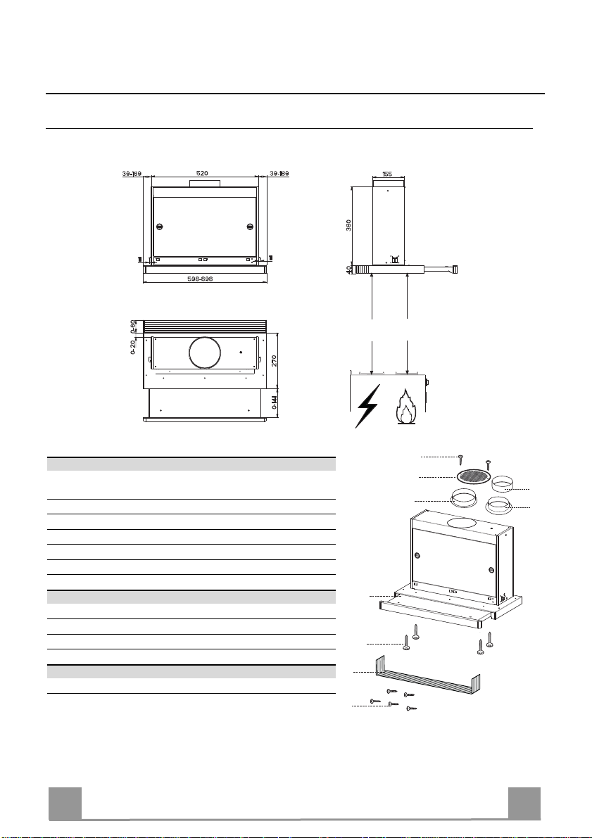
Dimensions
Min.
450mm
Min.
650mm
Components
Ref. Q.ty Product Components
1 1 Hood Body, complete with: Controls, Light, Blower,
8 1 Directional Air Outlet grille
9 1 Flange ø 150 mm
10a 1 Flange ø 120 mm
10b 1 Adapting ring ø 120-125 mm
20 1 Closing element
Ref. Q.ty Installation Components
12a 4 Screws 3,5 x 16
12e 2 Screws 2,9 x 12,7
12f 5 Screws 2,9 x 9,5
Q.ty Documentation
1 Instruction Manual
Filters
EN
12f
12e
8
9
1
12a
20
10b
10a
4
4
2
5
INSTALLATION
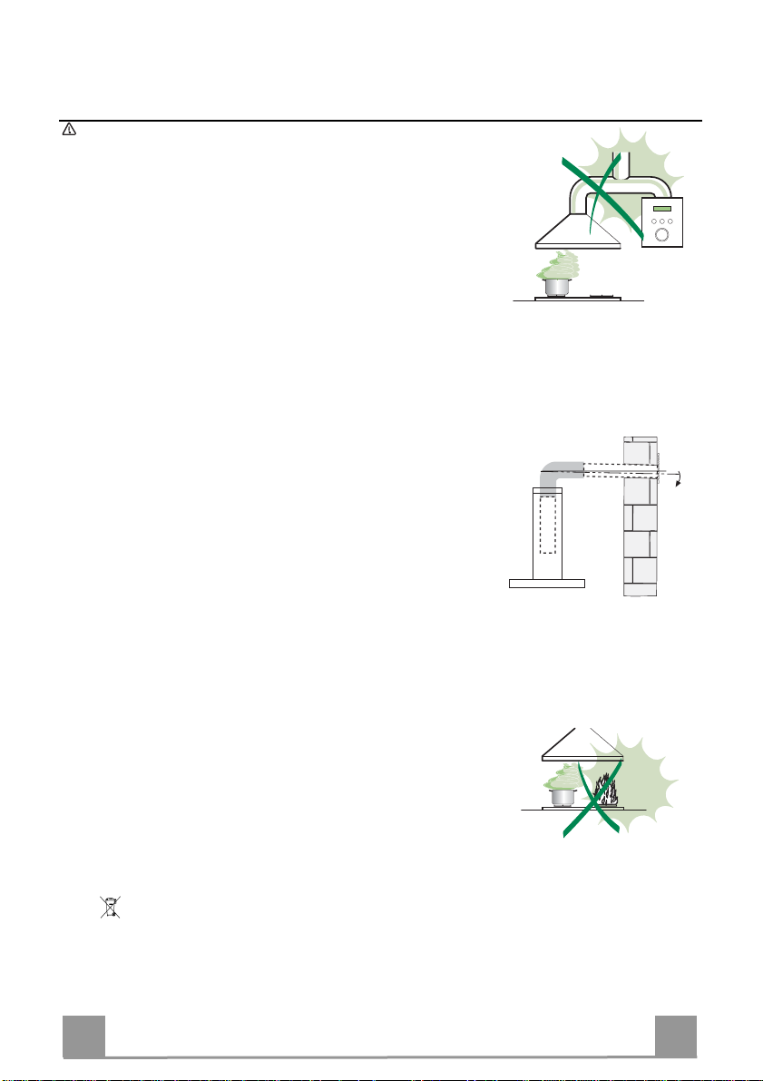
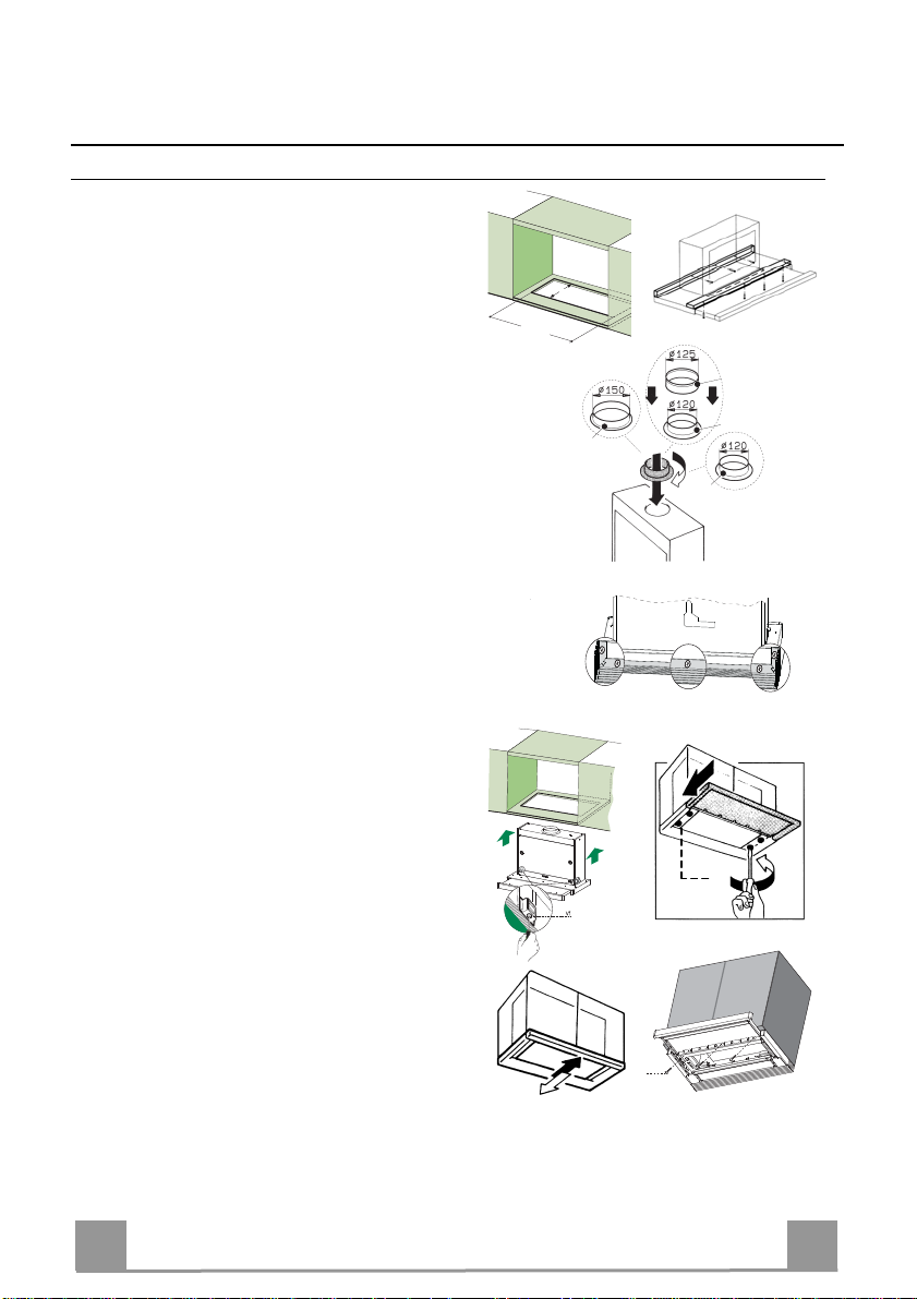
Drilling the Support surface and Fitting the Hood
• The Hood can be fitted directly on the
lower surface of the Wall Units (650 mm
min. above the Cooker Top) using the snapon Side Supports.
• Make an opening on the lower surface of
the Wall Unit, as indicated. (fig.1)
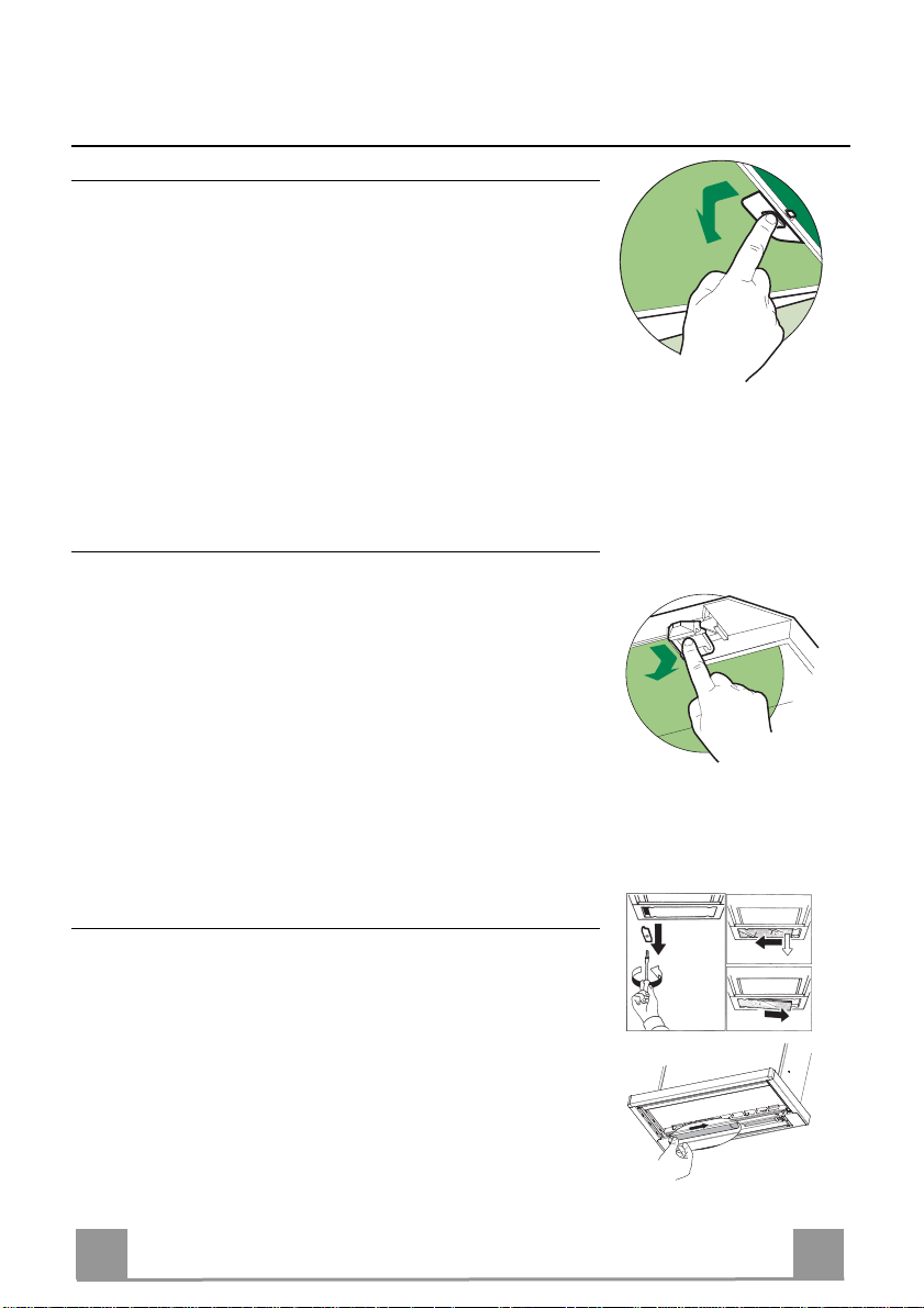
• Before carrying out the installation, the
wooden transportation protections screwed
on the visor and on the canopy body must
be removed. (fig.2)
• Choose the correct flange measure basing
on the air outlet diameter and insert it to the
upper air outlet opening. (fig.3)
• Screw the closing profile 20 onto the rear
part of the hood, using the screws 12f (2.9
x 9.5) provided. (fig.4)
• Open the sliding suction panel.
• Remove the metal grease filters one by one
after having disconnected the relative fastening elements.
• Close the sliding suction panel again.
• Insert the Hood until the snap-on side supports click into place. (fig.5)
• Open the sliding suction panel.
• Lock in position by tightening the screws
Vf from underneath the Hood. (fig.5)
• If necessary, adjust the whole filter holder
unit and proceed as follows:
• Loosen the four adjustment screws Vr
and close the sliding panel again. (fig.6)
• Move the entire filter holder unit until it
is properly aligned with the wall unit.
(fig.7)
• Keeping the hood canopy still, remove
the sliding panel and lock the adjustment
screws again. (fig.6)
• The hood can now be fastened to the
wall unit using the four screws 12a (3.5
x 16) provided. (fig.8)
• Replace the metal grease filters.
• Close the sliding suction panel again.
1
162
523
10b
10a
9
10a
3
4
Vr
6
7
12a
8
EN
5
5
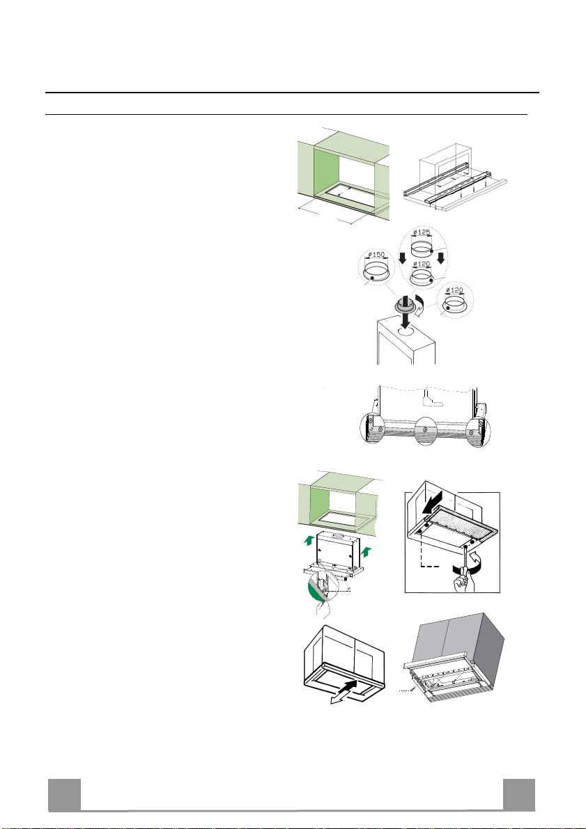
Connections
DUCTING VERSION AIR EXHAUST SYSTEM
When installing the hood in ducting version, a rigid or a
flexible pipe with the diameter corresponding to the
flange diameter is used in order to connect the hood to
the air outlet piping.
• Fix the pipe with an adequate quantity of pipe
clamps (not supplied).
• Remove possible charcoal filters.
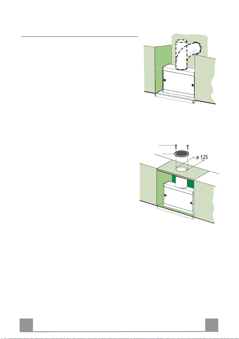
RECIRCULATION VERSION AIR OUTLET
• Cut a hole ø 125 mm in any shelf that may be positioned over the hood.
• Insert the flange 10a on the hood body outlet.
• Connect the flange to the outlet on the shelf over the
hood using a flexible or rigid pipe ø120 mm.
• Fix the pipe in position using sufficient pipe clamps
(not supplied).
• Fix the directional grille 8 on the recirculation air
outlet using the 2 screws 12e (2,9 x 12,7) provided.
• Ensure that the activated charcoal filters have been
inserted.
12e
8
ELECTRICAL CONNECTION
• Connect the hood to the mains through a two-pole switch having a contact gap of at least 3
mm..
EN
6
6

USE
L
M
By pulling out the sliding panel it is possible to automatically activate all the hood functions.
By simply closing the sliding panel all the functions are switched off.
SWITCH FUNCTIONS
L Light Switches the lighting system on and off
M Motor Switches the extractor motor on and off
1. Low speed, used for a continuous and silent air change in the presence
of light cooking vapour.
2. Medium speed, suitable for most operating conditions, thanks to an optimum relation between hood performance and noise.
3. Maximum speed, suitable when the highest cooking vapour emission
has to be eliminated for longer periods.
i. Intensive speed, suitable for the strongest cooking vapours and odours.
EN
7
7
MAINTENANCE
Grease filters
CLEANING METAL CASSETTE GREASE FILTERS
• The filters must be cleaned every 2 months, or more frequently
in case of particularly heavy use of the hood. Filters can be
washed in a dishwasher.
• Pull out the sliding suction panel.
• Remove the filters one by one, after having disconnected the
relative fastening elements.
• Wash the filters, taking care not to bend them. Let them get dry
before refitting them. (The colour of the filter surface may
change throughout the time but this has no influence to the filter efficiency).
• When refitting the filters, make sure that the handle is visible
on the outside.
• Close the sliding suction panel.
Charcoal filter (Recycling version)
REPLACING CHARCOAL FILTERS
Warning: Turn the lights off and wait until the lamps cool down
before you change the odour filter.
• These filters are not washable and cannot be regenerated, and
must be replaced approximately every four months or more
frequently by particularly heavy use.
• Pull out the sliding suction panel.
• Remove the grease filters.
• Remove the saturated carbon filter by releasing the fixing
hooks
• Fit the new filter by hooking it into its seating.
• Replace the grease filters.
• Close the sliding suction panel.
Lighting
LIGHT REPLACEMENT
9 W fluorescent lights.
• Remove the metal terminals fixing the glass.
• Slide the glass cover out of one of the fastening clips. Lower
the unfastened part of the glass cover slightly, so that the cover
can be completely removed.
• Replace the light with a new one of the same type and rating.
• Replace the glass cover in reverse order.
EN
8
8

2°
CONSEILS ET SUGGESTIONS
La présente notice d'emploi vaut pour plusieurs versions de l'appareil. Elle peut contenir des descrip-
tions d'accessoires ne figurant pas dans votre appareil.
INSTALLATION
• Le fabricant décline toute responsabilité en cas de dommage dû à une installation non correcte ou
non conforme aux règles de l’art.
• La distance minimale de sécurité entre le plan de cuisson et la hotte doit être de 650 mm au moins
(certains modèles peuvent être installés à une hauteur inférieure : se reporter aux paragraphes
« Encombrement » et « Installation »).
• Vérifier que la tension du secteur correspond à la valeur qui figure sur la plaquette apposée à
l’intérieur de la hotte.
• Pour les Appareils appartenant à la Ière Classe, veiller à ce que la mise à la terre de l’installation
électrique domestique ait été effectuée conformément aux normes en vigueur.
• Connecter la hotte à la sortie d’air aspiré à l’aide d’une tuyauterie d’un diamètre égal ou supérieur à
120 mm. Le parcours de la tuyauterie doit être le plus court possible.
• Ne pas connecter la hotte à des conduites d’évacuation de fumées issues d’une combustion tel que
(Chaudière, cheminée, etc…).
• Si vous utilisez des appareils qui ne fonctionnent pas à l’électricité dans la pièce ou est installée la
hotte (par exemple: des appareils fonctionnant au gaz), vous devez prévoir une aération
suffisante du milieu. Si la cuisine en est dépourvue, pratiquez une ouverture qui communique
avec l’extérieur pour garantir l’infiltration de l’air pur. Pour un emploi correct et sans risque, la
dépression maximum dans la pièce ne doit pas dépasser 0,04 mbar.
• En cas d’endommagement du cordon d’alimentation, faites-le remplacer par le constructeur ou par le
service après-vente, afin de prévenir tout risque.
UTILISATION
• La hotte a été conçue exclusivement pour l’usage domestique, dans le but d’éliminer les odeurs de la
cuisine.
• Ne jamais utiliser abusivement la hott e.
• Ne pas laisser les flammes libres à forte intensité quand la hotte est en service.
• Toujours régler les flammes de manière à éviter toute sortie latérale de ces dernières par rapport au
fond des marmites.
• Contrôler les friteuses lors de l’utilisation car l’huile sur chauffée pourrait s’enflammer.
• Ne pas préparer d’aliments flambés sous la hot te de cuisine : risque d’incendie
• Cet appareil ne doit pas être utilisé par des personnes (y compris les enfants) ayant des capacités
psychiques, sensorielles ou mentales réduites, ni par des personnes n’ayant pas l’expérience et la
connaissance de ce type d’appareils, à moins d'être sous le contrôle et la formation de personnes
responsables de leur sécurité.
• Les enfants doivent être surveillés pour s'assurer qu'ils ne jouent pas avec l'appar eil.
• « ATTENTION : Les parties accessibles peuvent devenir très chaudes si utilisées avec des appareils
de cuisson. »
ENTRETIEN
• Avant de procéder à toute opération d’entretien, débrancher la hotte en retirant la fiche ou en actionnant l’interrupteur général.
• Effectuer un entretien scrupuleux et en temps dû des Filtres, à la cadence conseillée (Risque
d’incendie).
• Pour le nettoyage des surfaces de la hotte, il suff it d’utiliser un chiffon humide et détersif liquide neutre.
Le symbole sur le produit ou son emballage indique que ce produit ne peut être traité comme déchet
ménager. Il doit plutôt être remis au point de ramassage concerné, se chargeant du recyclage du matériel
électrique et électronique. En vous assurant que ce produit est éliminé correctement, vous favorisez la prévention des conséquences négatives pour l’environnement et la santé humaine qui, sinon, seraient le résultat
d’un traitement inapproprié des déchets de ce produit. Pour obtenir plus de détails sur le recyclage de ce
produit, veuillez prendre contact avec le bureau municipal de votre région, votre service d’élimination des
déchets ménagers ou le magasin où vous avez acheté le produit.
FR
9
9
CARACTERISTIQUES
Encombrement
Min.
450mm
Min.
650mm
Composants
Réf. Q.té Composants de Produit
1 1 Corps Hotte équipé de: Commandes, Lumière, Groupe
8 1 Grille orientée Sortie de l’Air
9 1 Flasque ø 150 mm
10a 1 Flasque ø 120 mm
10b 1 Anneau de raccord Ø 120 - 125 mm
20 1 Profil fermeture
Réf. Q.té Composants pour l ’installation
12a 4 Vis 3,5 x 16
12e 2 Vis 2,9 x 12,7
12f 5 Vis 2,9 x 9,5
Q.té Documentation
1 Manuel d’instructions
Ventilateur, Filtres
FR
12f
12e
8
9
1
12a
20
10b
10a
1
10
2
5
INSTALLATION
Perçage du Plan de support et Montage de la Hotte
• Il est possible d’installer la Hotte directement
sur le plan inférieur des Armoires murales (650
mm. min. par rapport aux Plaques de Cuisson), à
l’aide des Supports latéraux par encliquetage.
• Percer une ouverture (emboîtage) sur le plan
inférieur de l’Armoire murale, comme indiqué.
(fig.1)
• Avant de procéder au montage de la hotte, il
faut enlever les protections transport en bois
vissées sur la partie inférieure et sur la carrosserie de la hotte. (fig.2)
• Selon la base du diamètre de sortie de l’air choisi, insérer la flasque correcte dans le trou supérieur de sortie de l’air. (fig.3)
• Visser le profil de fermeture 20 sur la partie
arrière de la hotte, en utilisant les vis 12f (2,9 x
9,5) fournies avec l’appareil. (fig.4)
• Sortir le chariot aspirant.
• Retirer les Filtres Anti-graisse l’un après l’autre,
en intervenant sur les crochets spécialement
prévus.
• Fermer le chariot aspirant.
• Insérer la Hotte jusqu’à accrocher les Supports
latéraux par encliquetage. (fig.5)
• Sortir le chariot aspirant.
• Bloquer définitivement la pièce, en serrant les
Vis Vf depuis le dessous de la Hotte. (fig.5)
• Si nécessaire, effectuer des ajustements du corps
porte-filtres tout entier, puis suivre les instructions suivantes:
• Desserrer les quatre vis de réglage Vr et re-
fermer le chariot. (fig.6)
• Déplacer le corps porte-filtres tout entier, jus-
qu’à obtenir l’alignement souhaité de l’armoire murale. (fig.7)
• Toujours en maintenant bloqué le corps de la
hotte, sortir le chariot et bloquer à nouveau les
vis de réglage. (fig.6)
• Maintenant il est possible de fixer définitive-
ment la hotte contre l’armoire murale en utilisant les quatre vis 12a (3,5 x 16) fournies
avec l’appareil. (fig.8)
• Remonter les Filtres anti-graisse.
• Sortir le chariot aspirant
1
162
523
10b
10a
9
10a
3
4
Vr
6
7
12a
8
FR
1
11

Branchements
SORTIE AIR VERSION EVACUATION EXTERIEURE
En cas d’installation en version evacuation exterieure,
brancher la hotte à la tuyauterie de sortie utilisant un
tube rigide ou flexible avec le même diamètre de la
flasque précédemment installée.
• Fixer le tube par des colliers appropriés. Le matériau
nécessaire n’est pas fourni.
• Retirer les éventuels filtres anti-odeur au charbon
actif.
SORTIE AIR VERSION RECYCLAGE
• Percer un trou de ø 125 mm. sur l’éventuelle Tablette
qui se trouve au-dessus de la Hotte.
• Insérer le flasque 10a sur la sortie du corps de la
hotte.
• Connecter la Flasque au trou de sortie sur la Tablette
qui se trouve au-dessus de la Hotte, au moyen d’un
tuyau rigide ou flexible de ø120 mm.
• Fixer le tube par des colliers appropriés. Le matériau
nécessaire n’est pas fourni.
• Fixer la Grille orientée 8 sur la sortie de l’air recyclé
à l’aide de 2 Vis 12e (2,9 x 12,7) fournies avec l’appareil.
• S’assurer de la présence des filtres anti-odeur au
charbon actif.
12e
8
BRANCHEMENT ELECTRIQUE
• Brancher la hotte sur le secteur en interposant un interrupteur bipolaire avec ouverture des
contacts d’au moins 3 mm.
FR
1
12
 Loading...