

Page 1

User manual
Manual de instrucciones
Manual de instruções
EFA 9673 - 90673
Page 2

Page 3

WW
elcome to the world of Electrelcome to the world of Electr
W
elcome to the world of Electr
WW
elcome to the world of Electrelcome to the world of Electr
oluxolux
olux
oluxolux
Thank you for choosing a first class
product from Electrolux, which
hopefully will provide you with lots of
pleasure in the future. The Electrolux
ambition is to offer a wide variety of
quality products that make your life
more comfortable. You find some
examples on the cover in this manual.
Please take a few minutes to study this
manual so that you can take advantage
of the benefits of your new machine.
We promise that it will provide a
superior User Experience delivering
Ease-of-Mind.
Good luck!
electroluxelectrolux
electrolux
electroluxelectrolux
safety warnings
33
3
33
GB
Page 4
44
electr electr
electr
electr electr
oluxolux
olux contents
oluxolux
4
44
Contents
GB
Safety warnings ................................ 5
Description of the Appliance ............. 7
Control Panel.................................... 8
Maintenance and Care ................... 11
Special accessories ........................ 16
Something Not Working.................. 16
Installation ...................................... 17
The following symbols are used in this user manual:
Important information concerning your personal safety and information on
how to avoid damaging the appliance.
General information and tips.
Environmental information.
Page 5
Safety warnings
For the userFor the user
For the user
For the userFor the user
• The cooker hood is designed to
extract unpleasant odours from the
kitchen, it will not extract steam.
• Always cover lighted elements, to
prevent excess heat from damaging
the appliance. In the case of oil, gas
and coal fired cookers it is essential
to avoid open flames.
• Also, when frying, keep the deep
frying pan on the cooker top/cooker
under careful control.
• The hot oil in the frying pan might
ignite due to overheating.
• The risk of self-ignition increases
when the oil being used is dirty.
• It is extremely important to note that
overheating can cause a fire.
Never carry out any flambé cookingNever carry out any flambé cooking
•
Never carry out any flambé cooking
Never carry out any flambé cookingNever carry out any flambé cooking
under the hood.under the hood.
under the hood.
under the hood.under the hood.
Always disconnect the unit frAlways disconnect the unit fr
•
Always disconnect the unit fr
Always disconnect the unit frAlways disconnect the unit fr
power supply beforpower supply befor
power supply befor
power supply beforpower supply befor
any work on the hood, includingany work on the hood, including
any work on the hood, including
any work on the hood, includingany work on the hood, including
rr
eplacing the light bulbeplacing the light bulb
r
eplacing the light bulb (take the
rr
eplacing the light bulbeplacing the light bulb
e carrying oute carrying out
e carrying out
e carrying oute carrying out
cartridge fuse out of the fuse holder
or switch off the automatic circuit
breaker).
It is very important to clean the hoodIt is very important to clean the hood
•
It is very important to clean the hood
It is very important to clean the hoodIt is very important to clean the hood
and rand r
eplace the filter at theeplace the filter at the
and r
eplace the filter at the
and rand r
eplace the filter at theeplace the filter at the
rr
ecommended intervals. Failurecommended intervals. Failur
r
ecommended intervals. Failur
rr
ecommended intervals. Failurecommended intervals. Failur
do so could cause grdo so could cause gr
do so could cause gr
do so could cause grdo so could cause gr
to build up, rto build up, r
to build up, r
to build up, rto build up, r
esulting in a firesulting in a fir
esulting in a fir
esulting in a firesulting in a fir
ease depositsease deposits
ease deposits
ease depositsease deposits
• The appliance is not intended for use
by young children or infirm persons
without supervision.
• Older children must be supervised if
using the appliance.
om theom the
om the
om theom the
e toe to
e to
e toe to
e hazare hazar
e hazar
e hazare hazar
electroluxelectrolux
electrolux
electroluxelectrolux
safety warnings
• Young children should be supervised
to ensure that they do not play with
the appliance.
••
WW
ARNING - ARNING -
•
W
ARNING - Ensure that the
••
WW
ARNING - ARNING appliance is switched off before
replacing the lamp to avoid the
possibility of electric shock.
This appliance is marked according to
the European directive 2002/96/EC on
Waste Electrical and Electronic
Equipment (WEEE).
By ensuring this product is disposed of
correctly, you will help prevent potential
negative consequences for the
environment and human health, which
could otherwise be caused by
inappropriate waste handling of this
product.
The symbol
on the product, or on
the documents accompanying the
product, indicates that this appliance
may not be treated as household
waste. Instead it should be taken to the
appropriate collection point for the
recycling of electrical and electronic
equipment.
Disposal must be carried out in
d.d.
d.
d.d.
accordance with local environmental
regulations for waste disposal.
For more detailed information about
treatment, recovery and recycling of
this product, please contact your local
council, your household waste disposal
service or the shop where you
purchased the product.
55
5
55
GB
Page 6

66
6
66
electr electr
oluxolux
electr
olux safety warnings
electr electr
oluxolux
For the installerFor the installer
For the installer
For the installerFor the installer
• When used as an extractor unit, the
GB
hood must be fitted with a hose
having preferably the same diameter
as the outlet hole.
Attention: Attention:
Attention: The hose is not supplied
Attention: Attention:
and must be purchased separately.
••
When installing the hood, make surWhen installing the hood, make sur
•
When installing the hood, make sur
••
When installing the hood, make surWhen installing the hood, make sur
you observe the following minimumyou observe the following minimum
you observe the following minimum
you observe the following minimumyou observe the following minimum
distance frdistance fr
distance fr
distance frdistance fr
cooking hob/ring surfaces:cooking hob/ring surfaces:
cooking hob/ring surfaces:
cooking hob/ring surfaces:cooking hob/ring surfaces:
electric cookerselectric cookers
electric cookers
electric cookerselectric cookers
gas cookersgas cookers
gas cookers
gas cookersgas cookers
om the top edge of theom the top edge of the
om the top edge of the
om the top edge of theom the top edge of the
If the instructions for installation for
the gas hob specify a greater
distance, this must be adhered to.
• The national Standard on fuelburning systems specifies a maximum depression of 0.04 mbar in
such rooms.
• The air outlet must not be connected
to chimney flues or combustion gas
ducts. The air outlet must under no
circumstances be connected to
ventilation ducts for rooms in which
fuel-burning appliances are installed.
• The air outlet installation must comply
with the regulations laid down by the
relevant local authorities.
• When the unit is used in extraction
mode, a sufficiently large ventilation
hole must be provided, with
dimensions that are approximately
the same as the outlet hole.
• National and regional building
regulations impose a number of
restrictions on using hoods and fuelburning appliances connected to a
chimney, such as coal or oil roomheaters and gas fires, in the same
room.
500 mm500 mm
500 mm
500 mm500 mm
650 mm650 mm
650 mm
650 mm650 mm
• Hoods can only be used safely with
appliances connected to a chimney if
the room and/or flat (air/environment
combination) is ventilated from
outside using a suitable ventilation
hole approximately 500-600 cm
large to avoid the possibility of a
depression being created during
operation of the hood.
• If you have any doubts, contact the
relevant controlling authority or
ee
e
ee
building inspector’s office.
• Since the rule for rooms with fuel
burning appliances is “outlet hole of
the same size as the ventilation hole”,
a hole of 500-600 cm2, which is to
say a larger hole, could reduce the
performance of the extractor hood.
• If the hood is used in its recirculation
mode, it will operate simply and safely
in the above conditions without the
need for any of the aforementioned
measures.
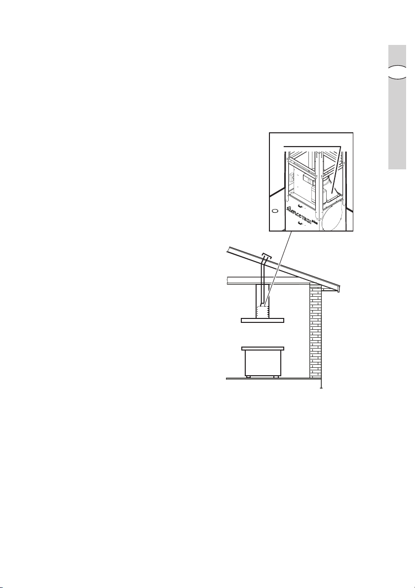
• When the hood is used in its
extraction mode, the following rules
must be followed to obtain optimal
operation:
- short and straight outlet hose
- keep bends in outlet hose to a
minimum
- never install the hoses with an
acute angle, they must always
follow a gentle curve.
- keep the hose as large as possible
(preferably the same diameter as
the outlet hole).
- the length should be no more than:
3 metres with one 90° bend
2 metres with two 90° bends
Bends of more than 90° will reduce
the efficiency of the hood and
reduce the airflow.
• Failure to observe these basic
instructions will drastically reduce the
performance and increase the noise
levels of the extractor hood.
2
Page 7
Description of the Appliance
The cooker hood is designed toThe cooker hood is designed to
•
The cooker hood is designed to
The cooker hood is designed toThe cooker hood is designed to
extract unpleasant odours frextract unpleasant odours fr
extract unpleasant odours fr
extract unpleasant odours frextract unpleasant odours fr
kitchen, it will not extract steam.kitchen, it will not extract steam.
kitchen, it will not extract steam.
kitchen, it will not extract steam.kitchen, it will not extract steam.
• The hood is supplied as an extractor
unit and can also be used with a
recirculation mode by fitting a
charcoal filter.
Only for EFOnly for EF
•
Only for EF
Only for EFOnly for EF
A 90673:A 90673:
A 90673: The cooker
A 90673:A 90673:
hood is supplied ready for use as a
recirculation hood and may be used
for extraction by removing the
charcoal filters.
Extraction modeExtraction mode
Extraction mode
Extraction modeExtraction mode
• In this mode fumes are extracted to
the outside via a
coupling ringcoupling ring
the
coupling ring.
coupling ringcoupling ring
hosehose
hose connected to
hosehose
• In order to obtain the best performance the hose should have a diameter
equal to the outlet hole.
om theom the
om the
om theom the
electrolux electrolux
electrolux description of the appliance
electrolux electrolux
Coupling ringCoupling ring
Coupling ring
Coupling ringCoupling ring
77
7
77
GB
RecirRecir
culation modeculation mode
Recir
culation mode
RecirRecir
culation modeculation mode
charchar
• The air is filtered through a
filterfilter
filter and returned to the kitchen.
filterfilter
char
charchar
coalcoal
coal
coalcoal
• You will need an original charcoal filter
for the recirculation mode. (See
Special Accessories).
Page 8

88
electr electr
8
88
oluxolux
electr
olux control panel
electr electr
oluxolux
Control Panel
GB
• Best results are obtained by using a
low speed for normal conditions and
a high speed when odours are more
concentrated.
Turn the hood on a few minutes
before you start cooking.
The hood should be left on after
cooking for about 15 minutes or until
all the odours have disappeared.
• The hood can also be commanded
from the control panel or the remote
control. (the remote control is a
special accessory and is ordered
separately).
CorrCorr
ect ventilation:ect ventilation:
•
Corr
ect ventilation: If the cooker
CorrCorr
ect ventilation:ect ventilation:
hood is to work correctly there must
be an under pressure in the kitchen.
It is important to keep the kitchen
windows closed and have a window
in an adjacent room open.
• The control switches are located on
the hood’s front panel
Page 9
electrolux electrolux
electrolux control panel
electrolux electrolux
99
9
99
Model EFModel EF
Model EF
Model EFModel EF
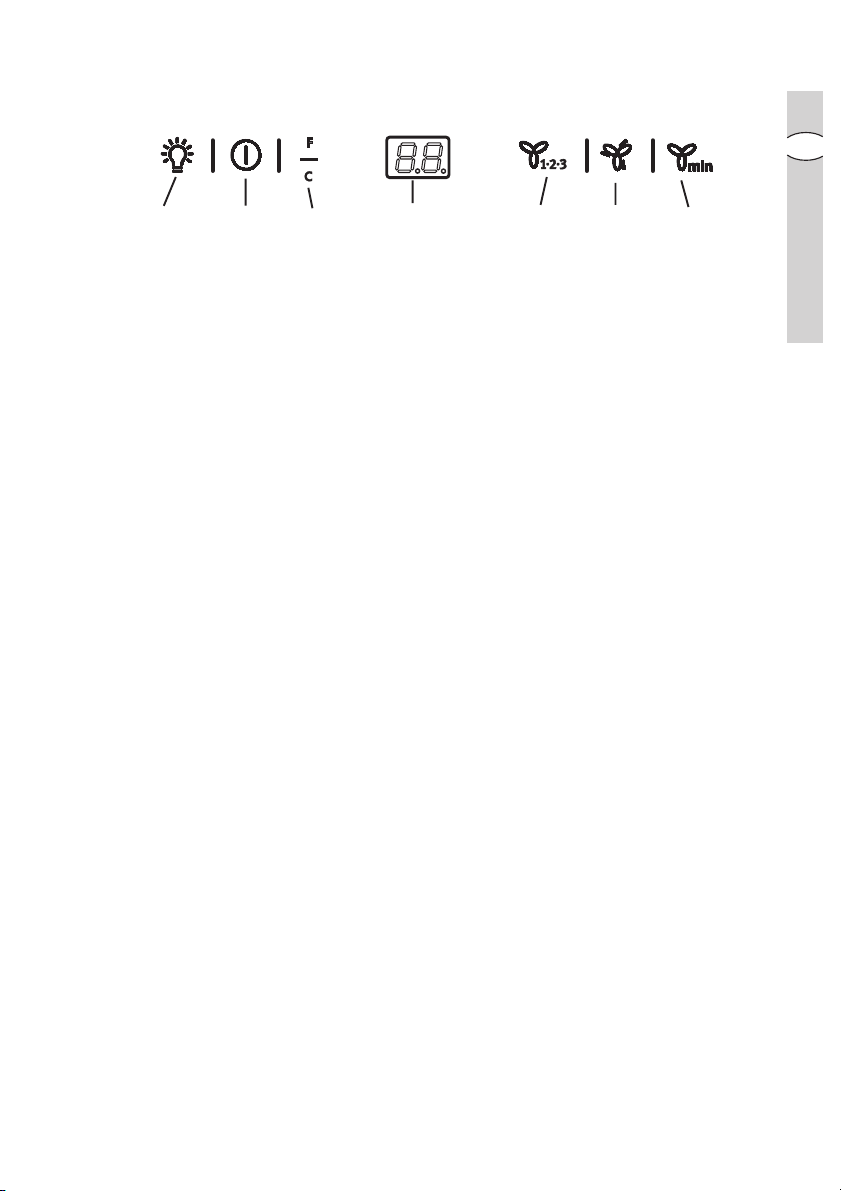
1.1.
Light switch, ON/OFF:Light switch, ON/OFF:
1.
Light switch, ON/OFF:press briefly to switch hob lighting on, press and hold
1.1.
Light switch, ON/OFF:Light switch, ON/OFF:
A 9673 - 90673A 9673 - 90673
A 9673 - 90673
A 9673 - 90673A 9673 - 90673
b
a
123 456
7
for more than 2 seconds to switch upper lighting on.
22
Mains switch, ON/OFFMains switch, ON/OFF
2.
Mains switch, ON/OFF
22
Mains switch, ON/OFFMains switch, ON/OFF
Press for less than 1 1/2 seconds and the cooker hood goes into the "
byby
by" position (dot
byby
“a”“a”
“a” on display is illuminated).
“a”“a”
Press for more than 1 1/2 seconds and the cooker hood turns OFF, ALL the
controls (except the light push button) are disabled (the display is off).
Press again for more than 1 1/2 seconds to reset the cooker hood to "stand
by".
3.3.
Filters saturation rFilters saturation r
3.
Filters saturation r
3.3.
Filters saturation rFilters saturation r
44
Start and choice of motor speed 1-2-3-1-2...Start and choice of motor speed 1-2-3-1-2...
4.
Start and choice of motor speed 1-2-3-1-2...
44
Start and choice of motor speed 1-2-3-1-2...Start and choice of motor speed 1-2-3-1-2...
55
Intensive speed ON/OFF: Intensive speed ON/OFF:
5.
Intensive speed ON/OFF: The Intensive speed runs for 5 minutes:
55
Intensive speed ON/OFF: Intensive speed ON/OFF:
eset key: eset key:
eset key: see the relative text on the following pages.
eset key: eset key:
If the hood is on when the Intensive speed is activated, the hood will revert to
previous speed after 5 minutes. If the hood is off when the Intensive speed is
activated, the hood will automatically turn off after 5 minutes.
The letter
P P
P appears on the display and the remaining time (the dot
P P
“b”“b”
“b” on
“b”“b”
display is flashing), if interrupted an acoustic signal is heard.
6
Self-TSelf-T
6
6.
66
imer ON/OFF: imer ON/OFF:
Self-T
imer ON/OFF: times all the speed levels (the dot
Self-TSelf-T
imer ON/OFF: imer ON/OFF:
“a”“a”
“a” on display is
“a”“a”
flashing), and then the cooker hood switches off:
The self-timer is set as follows:
st
1
speed level 20 minutes
2nd speed level 15 minutes
3rd speed level 10 minutes
The display shows the remaining operation time, at the end of the time an
acoustic signal is heard. Depressing the push-button again exits the function.
77
DisplayDisplay
7.
Display
77
DisplayDisplay
standstand
stand
standstand
GB
Should the hood or the controls fail to operate: disconnect the power supply for at
least 5 seconds. After reconnecting the power supply wait 15 seconds and then
check that the cooker hood is now operating correctly.
Page 10

1010
electr electr
10
1010
GrGr
Gr
GrGr
maintenance indicatormaintenance indicator
maintenance indicator
maintenance indicatormaintenance indicator
GB
oluxolux
electr
olux control panel
electr electr
oluxolux
ease and charease and char
ease and char
ease and charease and char
coal filtercoal filter
coal filter
coal filtercoal filter
This hood is fitted with a device that
indicates when it is necessary to clean
the grease filter or the charcoal filter (if
the hood is used in the recirculation
version with a charcoal filter).
On delivery , the hood is not supplied
EFEF
with a charcoal filter(
A 9673 ONLA 9673 ONL
EF
A 9673 ONL
EFEF
A 9673 ONLA 9673 ONL
so the saturation indicator will be
disabled.
If the hood is to be used with a
charcoal filter, the saturation
indicator light must be enabled as
follows:
Set in "
Press buttons
OFFOFF
OFF" the hood.
OFFOFF
33
3 and
33
44
4 simultaneously
44
and hold them for 3 seconds. At first
only the grease filter LED
FF
F will light up,
FF
but when the charcoal filter LED
lights up the saturation indicator will be
enabled.
To disable it: Press buttons
again simultaneously and hold
them for 3 seconds, until the charcoal
filter LED goes out.
33
3 and
33
Grease filter LED (F)
FF
LED
F will start to flash when it is time
FF
to clean the grease filter.
Cleaning will be necessary after 40
working hours. Always comply with the
maintenance instructions for the grease
filter.
Charcoal filter LED (C)
The charcoal filter LED
Y)Y)
Y),
Y)Y)
flash when the charcoal filter needs to
CC
C will start to
CC
be replaced.
This operation is necessary after
approximately 160 working hours.
Resetting the saturation indicator
After cleaning or replacing the filters,
press button
grease filter LED
CC
LED
C stops flashing.
CC
CC
C
CC
44
4
44
33
3 for 3 seconds until the
33
FF
F or the charcoal filter
FF
Page 11
Maintenance and Care
x 4
••
BeforBefor
•
••
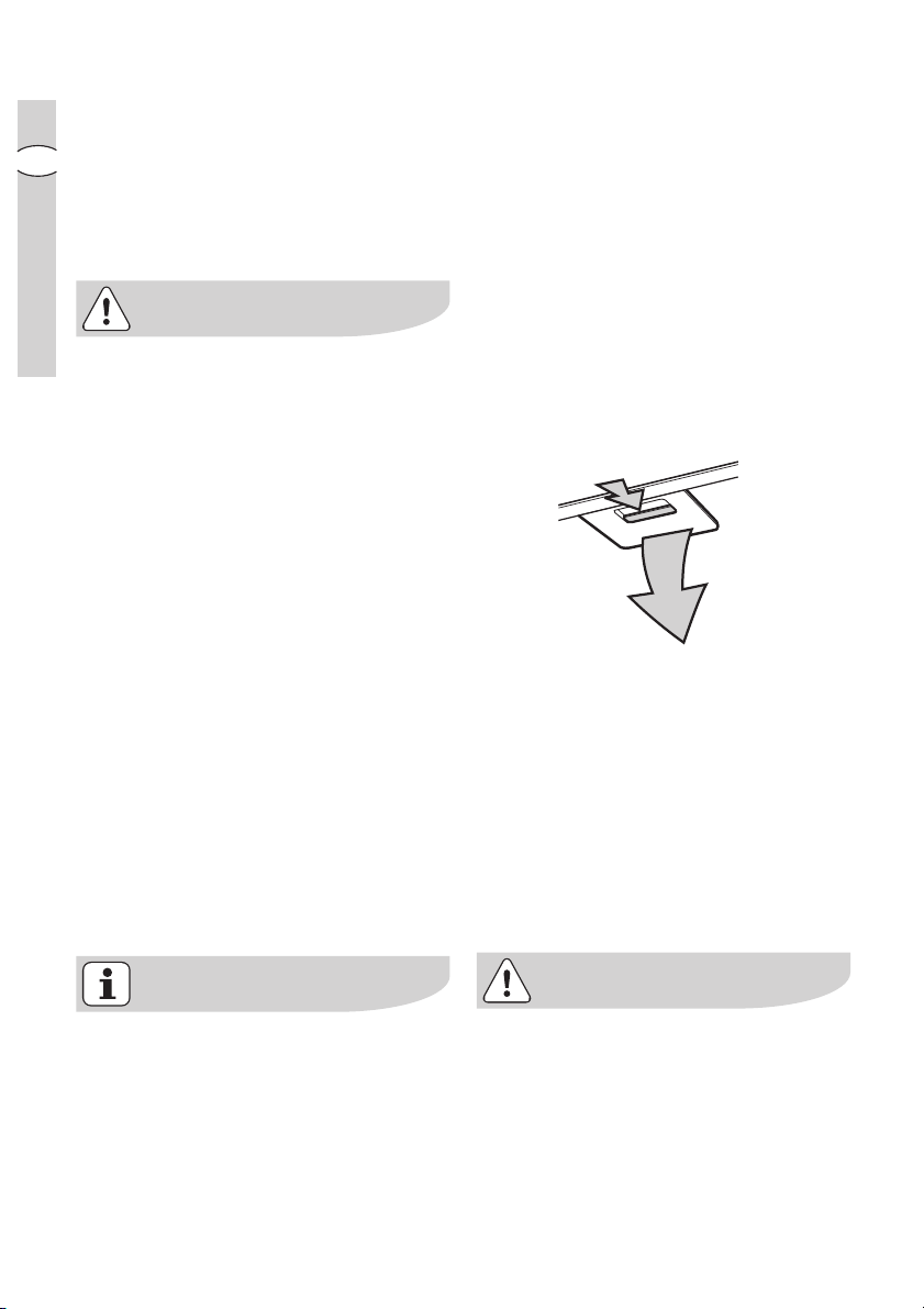
Air suction panelsAir suction panels
Air suction panels
Air suction panelsAir suction panels
Remove the perimeter air suction
panels to access the grease filters.
The perimeter air suction panels are
attached to the cooker hood by a
series of
pull them outwards and detach them
from the
Clean the perimeter air suction panels
as often as the grease filters (for more
information about gentle cleaning
methods, read the paragraph
“Cleaning” in the pages that follow).
e performing any maintenance operation, isolate the hood fre performing any maintenance operation, isolate the hood fr
Befor
e performing any maintenance operation, isolate the hood fr
BeforBefor
e performing any maintenance operation, isolate the hood fre performing any maintenance operation, isolate the hood fr
electrical supply by switching ofelectrical supply by switching of
electrical supply by switching of
electrical supply by switching ofelectrical supply by switching of
connector fuse.connector fuse.
connector fuse.
connector fuse.connector fuse.
Or if the appliance has been connected thrOr if the appliance has been connected thr
Or if the appliance has been connected thr
Or if the appliance has been connected thrOr if the appliance has been connected thr
plug must be rplug must be r
plug must be r
plug must be rplug must be r
pinspins
pins and
pinspins
fastening cablefastening cable
fastening cable.
fastening cablefastening cable
emoved fremoved fr
emoved fr
emoved fremoved fr
coupling springscoupling springs
coupling springs;
coupling springscoupling springs
om the socket.om the socket.
om the socket.
om the socket.om the socket.
f at the connector and rf at the connector and r
f at the connector and r
f at the connector and rf at the connector and r
electrolux electrolux
electrolux control panel
electrolux electrolux
om theom the
om the
om theom the
emoving theemoving the
emoving the
emoving theemoving the
ough a plug and socket, then theough a plug and socket, then the
ough a plug and socket, then the
ough a plug and socket, then theough a plug and socket, then the
1111
11
1111
GB
When refitting the perimeter air suction
panels, ALWAYS reattach the fastening
cables.
Make sure the panels are attached to
the cooker hood properly (snapfastened).
Page 12
1212
12
1212
electr electr
oluxolux
electr
olux maintenance and care
electr electr
oluxolux
Metal grMetal gr
Metal gr
Metal grMetal gr
ease filterease filter
ease filter
ease filterease filter
• The purpose of the grease filters is to
GB
absorb grease particles which form
during cooking and it
mustmust
must always be
mustmust
used, either in the external extraction
or internal re-circulation function.
Attention: the metal grease filters
must be removed and washed, either
by hand or in the dishwasher, every
four weeks.
Removing the metal grRemoving the metal gr
Removing the metal gr
Removing the metal grRemoving the metal gr
ease filterease filter
ease filter
ease filterease filter
• Use the spring handle and remove
the filter downward.
Hand washingHand washing
Hand washing
Hand washingHand washing
Soak grease filters for about one hour
in hot water with a grease-loosening
cleaner, then rinse off thoroughly with
hot water. Repeat the process if
necessary. Refit the grease filters
when they are dry.
DishwasherDishwasher
Dishwasher
DishwasherDishwasher
Place grease filters in the dishwasher.
Select most powerful washing
programme and highest temperature,
at least 65°C. Repeat the process.
Refit the grease filters when they are
dry.
When washing the metal grease filter
in the dishwasher a slight
discolouration of the filter can occur,
this does not have any impact on its
performance.
• Clean the inner housing using a hand
hot solution only(never use caustic
detergents, abrasive powders or
brushes).
Page 13
CharChar
coal filtercoal filter
Char
coal filter
CharChar
coal filtercoal filter
• The charcoal filter should only be
used if you want to use the hood in
recirculation mode.
• To do this you will need an original
charcoal filter (available from your
local Service Force Centre).
Cleaning/rCleaning/r
•
Cleaning/r
Cleaning/rCleaning/r
eplacing the chareplacing the char
eplacing the char
eplacing the chareplacing the char
coal filtercoal filter
coal filter
coal filtercoal filter
Unlike other charcoal filters, the
LONGLIFE charcoal filter can be
cleaned and reactivated.
With normal use the filter should be
cleaned every second month (when
using the hood 2.5 hours per day,on
avarage). The best way to clean the
filter is in the dishwasher. Use normal
detergent and choose the highest
temperature (65º C). Wash the filter
separately so that no food parts gets
stuck on the filter and later causes bad
odours. To reactivate the charcoal, the
filter should be dried in an oven for 10
minutes with a maximum temperature
of 100º C.
After approximately three years of use,
the charcoal filter should be replaced
with a new one, as the odour reduction
capacity will be reduced.
electrolux electrolux
electrolux maintenance and care
electrolux electrolux
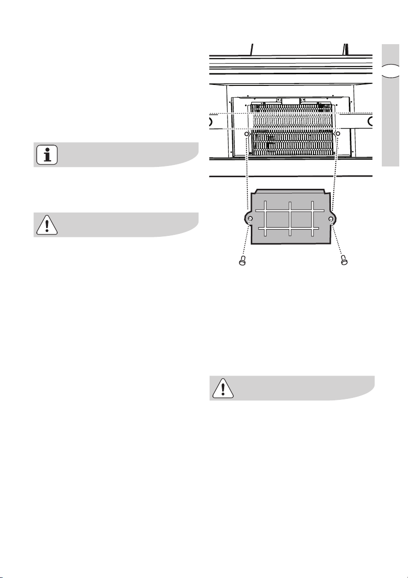
FittingFitting
•
Fitting
FittingFitting
Position the carbon filter inside the
hood to cover the protection grill of
the motor.
Fix the filter with 2 lateral knobs.
TT
o ro r
emoveemove
•
T
o r
emove proceed in the reverse
TT
o ro r
emoveemove
order.
• Always specify the hood model code
number and serial number when
ordering replacement filters. This
information is shown on the rating
plate located on the inside of the unit.
• The charcoal filter can be ordered
from your local Service Force Centre.
1313
13
1313
GB
Page 14
1414
electr electr
oluxolux
electr
olux maintenance and care
electr electr
oluxolux
ningning
ning
ningning
GB
14
1414
WW
W
WW
arar
ar
arar
• Failure to observe the instructions on
cleaning the unit and changing the
filters will cause a fire hazard. You are
therefore strongly recommended to
follow these instructions.
• The manufacturer declines all
responsibility for any damage to the
motor or any fire damage linked to
inappropriate maintenance or failure
to observe the above safety
recommendations.
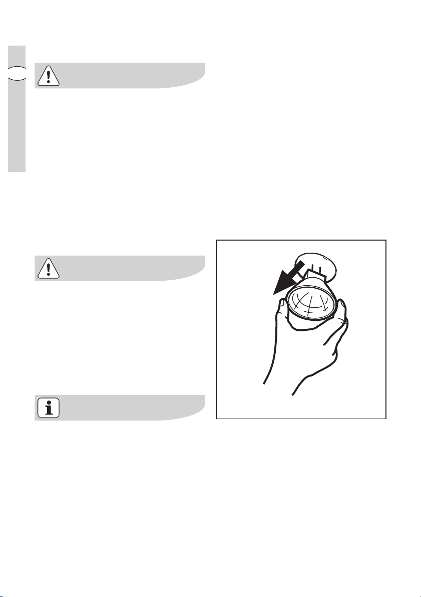
Changing the light bulb(s)Changing the light bulb(s)
Changing the light bulb(s)
Changing the light bulb(s)Changing the light bulb(s)
Disconnect the cooker hood frDisconnect the cooker hood fr
•
Disconnect the cooker hood fr
Disconnect the cooker hood frDisconnect the cooker hood fr
the mains supplythe mains supply
the mains supply
the mains supplythe mains supply
••
Prior to touching the light bulbsPrior to touching the light bulbs
•
Prior to touching the light bulbs
••
Prior to touching the light bulbsPrior to touching the light bulbs
ensurensur
e they are they ar
ensur
e they ar
ensurensur
e they are they ar
..
.
..
e cooled down.e cooled down.
e cooled down.
e cooled down.e cooled down.
omom
om
omom
• Replace the old bulb with a new one
of the same type.
• If the light does not come on, make
sure the bulb has been inserted in
correctly before contacting your local
Service Force Centre.
20W max20W max
20W max
20W max20W max
GU4 - 12 V - Ø 35mm - 30° - Dichroic
Page 15

Cleaning the hoodCleaning the hood
Cleaning the hood
Cleaning the hoodCleaning the hood
• Clean the outside of the hood using a
damp cloth and a solution of water
and mild washing up liquid.
• Never use corrosive, abrasive or
flammable cleaning products or
products containing bleach.
• Never insert pointed objects in the
motor’s protective grid.
• Only ever clean the switch panel and
filter grill using a damp cloth and mild
washing up liquid.
• Clean all the plastic parts with a soft
cloth soaked in warm water and
neutral soap.
• It is extremely important to clean the
unit and change the filters at the
recommended intervals. Failure to do
so will cause grease deposits to build
up that could constitute a fire hazard.
electrolux electrolux
electrolux maintenance and care
electrolux electrolux
1515
15
1515
GB
Page 16

1616
electr electr
16
1616
Special accessoriesSpecial accessories
Special accessories
Special accessoriesSpecial accessories
GB
CharChar
Char
CharChar
Remote contrRemote contr
Remote contr
Remote contrRemote contr
oluxolux
electr
olux special accessories
electr electr
oluxolux
coal filtercoal filter
coal filter Type 967
coal filtercoal filter
olol
ol RM 6940
olol
Something Not Working
If your appliance fails to work properly please carry out the following checks.
SymptomSymptom
Symptom
SymptomSymptom
The cooker hood will not start...
The cooker hood is not working
The cooker hood has switched off
during operation...
SolutionSolution
Solution
SolutionSolution
Check that: Check that:
Check that: The hood is connected
Check that: Check that:
to the electricity supply.
Check that a fan speed has been
selected.
Check that: Check that:
Check that: The fan speed is set high
Check that: Check that:
enough for the task.
The grease filters are clean.
The kitchen is adequately vented to
allow the entry of fresh air.
If set up for recirculation, check that
the charcoal filter is still effective.
If set up for extraction, check that the
ducting and outlets are not blocked.
The safety cut-out device has been
tripped. Turn off the hob and then wait
for the device to reset. If the hood has
been installed below the heights
indicated in the installation instructions
the motor will cut-out frequently which
will damage the hood.
If after all these checks, the problem persists, contact your local Service Centre,
quoting the model and serial number.
Please note that it will be necessary to provide proof of purchase for any inguarantee service calls.
In-guarantee customers should ensure that the above checks have been made as
the engineer will make a charge if the fault is not a mechanical or electrical
breakdown.
Page 17

Installation
electrolux electrolux
electrolux installation
electrolux electrolux
1717
17
1717
TT
echnical Detailsechnical Details
T
echnical Details
TT
echnical Detailsechnical Details
EFEF
A 9673 (EFA 9673 (EF
EF
A 9673 (EF
EFEF
A 9673 (EFA 9673 (EF
Dimensions (in cm):Dimensions (in cm):
Dimensions (in cm):
Dimensions (in cm):Dimensions (in cm):
Height (Extraction mode): 89,5 ÷ 118,5
Height (Recirculation mode): 89,5 ÷ 129,5
Width: 99,8
Depth: 70
Maximum absorbed power:Maximum absorbed power:
Maximum absorbed power:
Maximum absorbed power:Maximum absorbed power:
350 W350 W
350 W
350 W350 W
Motor: 250 W
Lighting: 5 x 20 W
Length of the cable:Length of the cable:
Length of the cable:
Length of the cable:Length of the cable:
Electrical connection:Electrical connection:
Electrical connection:
Electrical connection:Electrical connection:
Fuse rating:Fuse rating:
Fuse rating:
Fuse rating:Fuse rating:
Mounting accessories includedMounting accessories included
Mounting accessories included
Mounting accessories includedMounting accessories included
150 cm150 cm
150 cm
150 cm150 cm
220-240 V220-240 V
220-240 V
220-240 V220-240 V
5A T5A T
5A T
5A T5A T
1 Allan wrench for torx screws
12 nuts
6 screws 6 x 70 mm
6 dowels Ø 10 mm
12 screws 4 x 7 mm
58 screws 3.5 x 9.5
1 deflector (with extensions)
A 90673)A 90673)
A 90673)
A 90673)A 90673)
GB
Page 18
1818
18
1818
electr electr
oluxolux
electr
olux installation
electr electr
oluxolux
Electrical connection
(not for UK)
GB
Safety warSafety war
Safety war
Safety warSafety war
Before connecting the appliance to the
power supply, check that the voltage
indicated on the rating plate
corresponds to the mains power supply
available. Appliances fitted with a plug
can be connected to any standard
power socket within easy access.
Should it be necessary to provide a
fixed connection, the hood must only
be installed by an electrician authorised
by the local electricity board. When
installing, an omnipolar disconnector
with a distance of at least 3 mm
between contacts must be provided.
Fixed connection of the appliance must
only be carried out by an authorised
electrician.
nings for the electriciannings for the electrician
nings for the electrician
nings for the electriciannings for the electrician
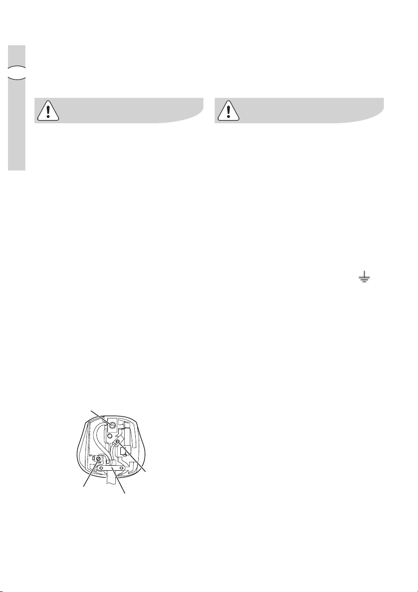
GREEN & YELLOW
Electrical connection for
UK only
Safety warSafety war
Safety war
Safety warSafety war
Connect the hood to the mains supply
via a double pole switch which has 3
mm minimum separation between the
contacts.
The switch must be accessible at all
times.
The following is valid in the United
Kingdom only:
- the wire which is coloured green and
yellow must be connected to the
terminal which is marked with the
letter E or by the earth symbol ( ),
or coloured green or green and
yellow;
- the wire which is coloured blue must
be connected to the terminal which is
marked with the letter N or coloured
black, -
- the wire which is coloured brown
must be connected to the terminal
which is marked with the letter L or
coloured red.
nings for the electriciannings for the electrician
nings for the electrician
nings for the electriciannings for the electrician
BLUE
5AT
BROWN
CORD CLAMP
Page 19
InstallationInstallation
Installation
InstallationInstallation
electrolux electrolux
electrolux installation
electrolux electrolux
1919
19
1919
GB
Make surMake sur
Make sur
Make surMake sur
carrying out the installation.carrying out the installation.
carrying out the installation.
carrying out the installation.carrying out the installation.
e that the cooker hood is disconnected fre that the cooker hood is disconnected fr
e that the cooker hood is disconnected fr
e that the cooker hood is disconnected fre that the cooker hood is disconnected fr
om the power supply beforom the power supply befor
om the power supply befor
om the power supply beforom the power supply befor
The cooker hood comes with fixing plugs which are suitable for use with most
walls/ceilings. Nevertheless, you should ask a qualified technician to assess the
suitability of the materials in accordance with the type of wall/ceiling. The wall/
ceiling must be sufficiently sturdy so as to support the weight of the cooker hood.
Remove the perimeter air suction panels and the grease filters.
Before installing the product:
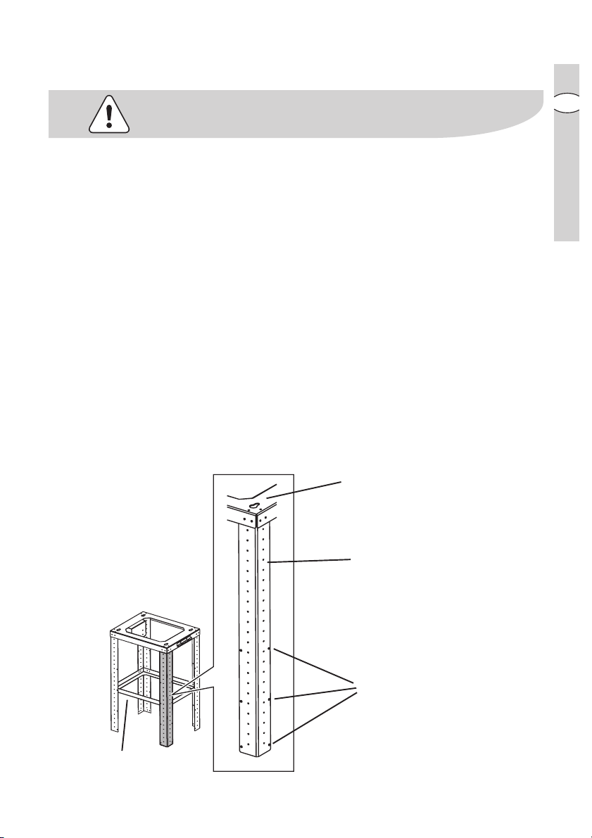
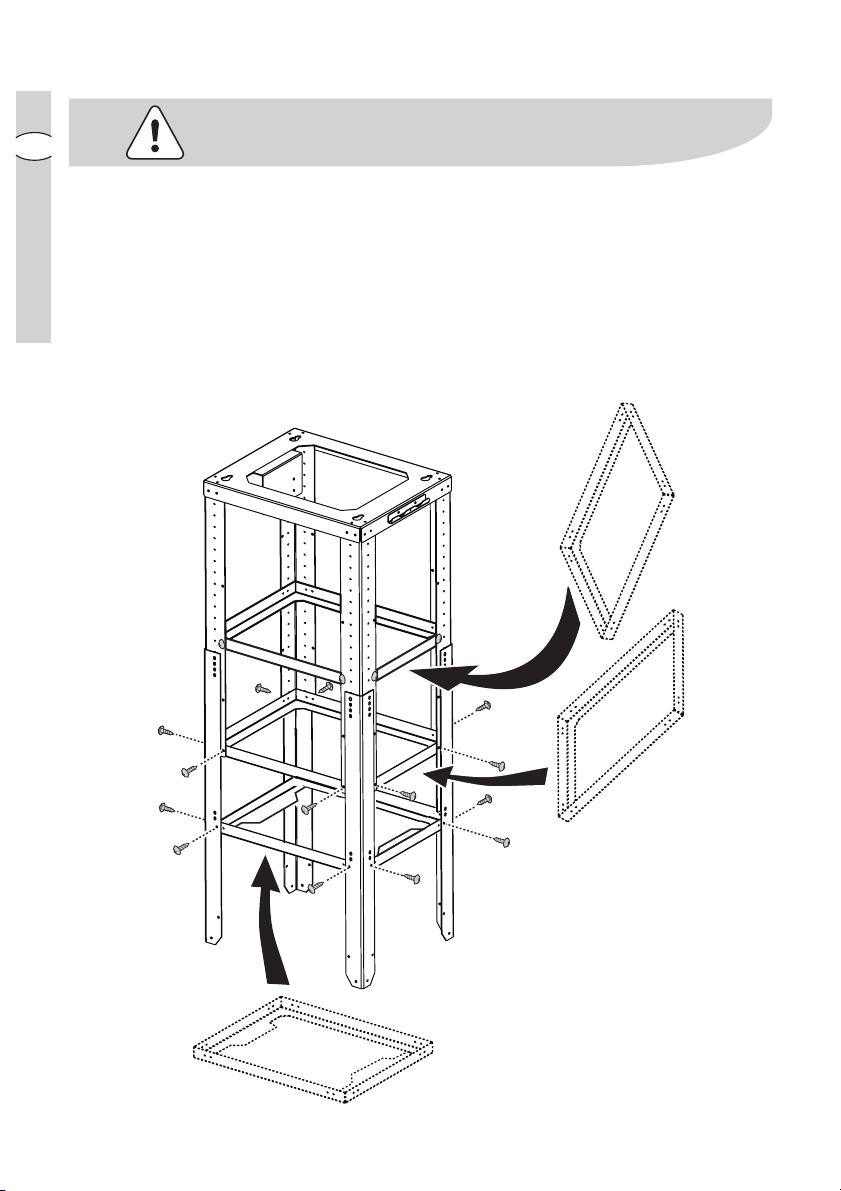
The perforated frame for the cooker hood is supplied prior to installation in parts.
The main parts making up the perforated frame are as follows:
• the upper perforated frame
• the perforated frame extension brackets
• the reinforcement brackets
2 are for use on the upper part
1 is for use on the lower part
Description of the upper perforated frame A:Description of the upper perforated frame A:
Description of the upper perforated frame A:
Description of the upper perforated frame A:Description of the upper perforated frame A:
AA
A (x1)
AA
BB
B (x4)
BB
CC
C (x3), of which:
CC
C1 - C1 -
C1 - 1 of which is pre-assembled
C1 - C1 -
C2C2
C2
C2C2
Point at which the perforated
frame is fixed/hooked to the
ceiling
Fixing points for extension
brackets
BB
B
BB
ee
e
ee
Reinforcement brackets
C1C1
C1
C1C1
Fixing points for the 2
reinforcement brackets
C1C1
C1
C1C1
Page 20
2020
20
2020
electr electr
oluxolux
electr
olux installation
electr electr
oluxolux
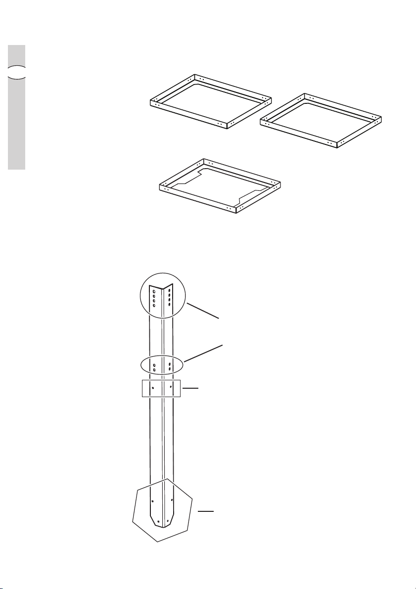
Description of the rDescription of the r
Description of the r
Description of the rDescription of the r
GB
reinforcement brackets
einforeinfor
cement brackets C1 and C2cement brackets C1 and C2
einfor
cement brackets C1 and C2
einforeinfor
cement brackets C1 and C2cement brackets C1 and C2
C1C1
C1
C1C1
(upper and intermediate)
reinforcement bracket
C2C2
C2 (lower)
C2C2
Description of the extension brackets B:Description of the extension brackets B:
Description of the extension brackets B:
Description of the extension brackets B:Description of the extension brackets B:
Points at which they
are fixed to the upper
frame
Fixing points for
the lower
reinforcement
bracket
C2C2
C2
C2C2
Points at which
the bracket is fixed
to the cooker
hood
Page 21
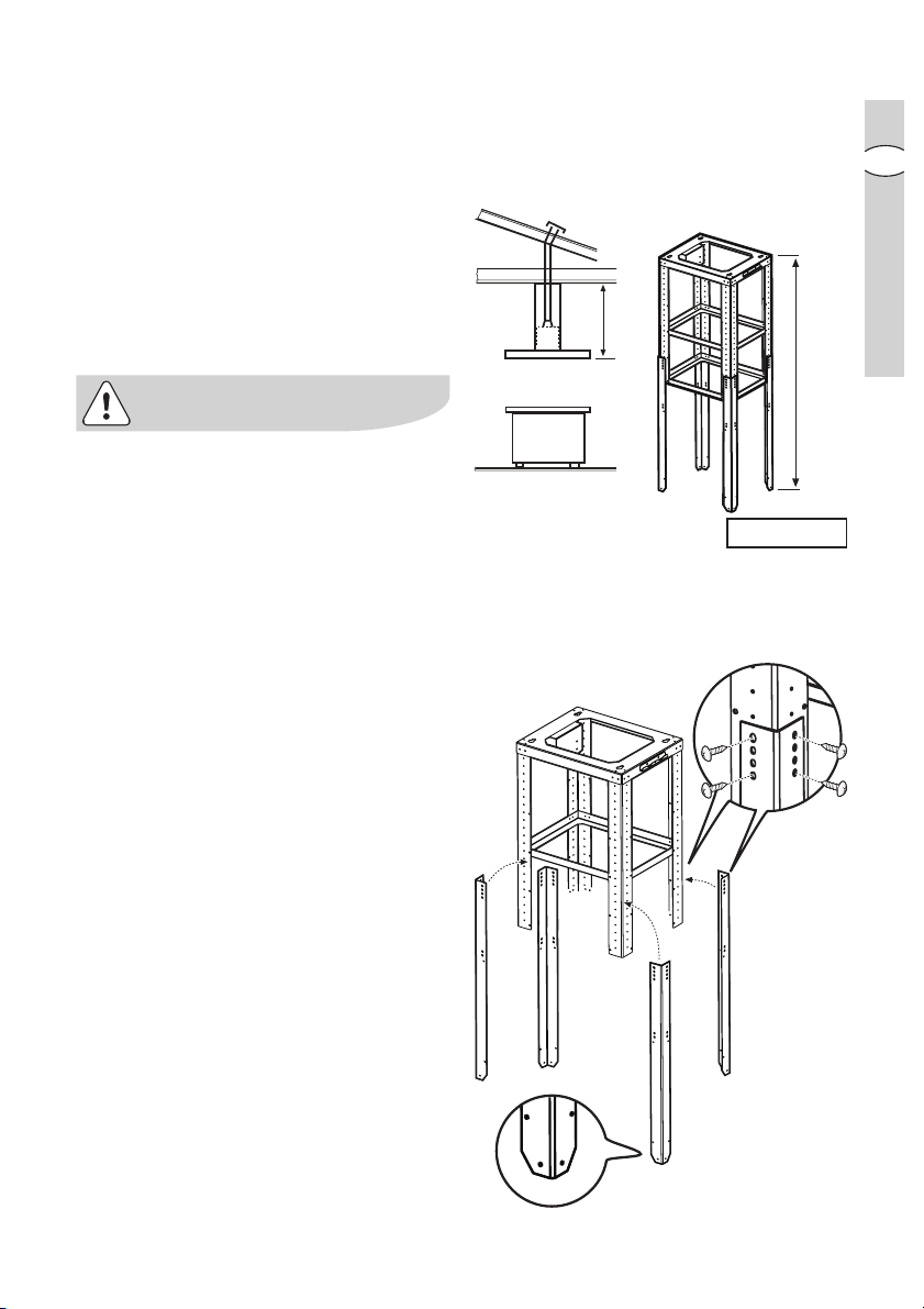
PrPr
L
E
E (mm)= L- 355
eparing the structural supporteparing the structural support
Pr
eparing the structural support
PrPr
eparing the structural supporteparing the structural support
Before assembling the perforated
frame, calculate the extension it
requires.
Use the formula given in the adjacent
diagram to help you.
Make a note of measurement
EE
E in this
EE
booklet; it will serve as a reference
when you are calculating the length of
the exhaust tube.
electrolux electrolux
electrolux installation
electrolux electrolux
2121
21
2121
GB
Measurement
LL
L should respect the
LL
minimum permitted distances from the
hob, as indicated in the paragraph
entitled “Safety warnings – for the
installer”.
• Fit the extension brackets
BB
B to the
BB
perforated frame using 4 screws for
each, so that the perforated frame
can be extended to the calculated
EE
length
E.
EE
Page 22
GB
2222
22
2222
electr electr
oluxolux
electr
olux installation
electr electr
oluxolux
For perforated frame extensions (please refer to measurement
previously):
smaller than 690 mm: smaller than 690 mm:
-
smaller than 690 mm: this extension requires only one bracket (
smaller than 690 mm: smaller than 690 mm:
this is already fixed in place.
between 690 mm and 795 mm: between 690 mm and 795 mm:
-
between 690 mm and 795 mm: fit both
between 690 mm and 795 mm: between 690 mm and 795 mm:
- greater than 800 mm: fit all available reinforcement brackets (
Use 8 screws to fix each reinforcement bracket in place.
Note:Note:
Note: One of the two
Note:Note:
supplied.
C1 C1
C1 brackets is usually already fitted when the appliance is
C1 C1
C1C1
C1 brackets.
C1C1
C1
EE
E calculated
EE
C1C1
C1); generally
C1C1
2 x C1 + 1 x C22 x C1 + 1 x C2
2 x C1 + 1 x C2)
2 x C1 + 1 x C22 x C1 + 1 x C2
C2
C1
Page 23
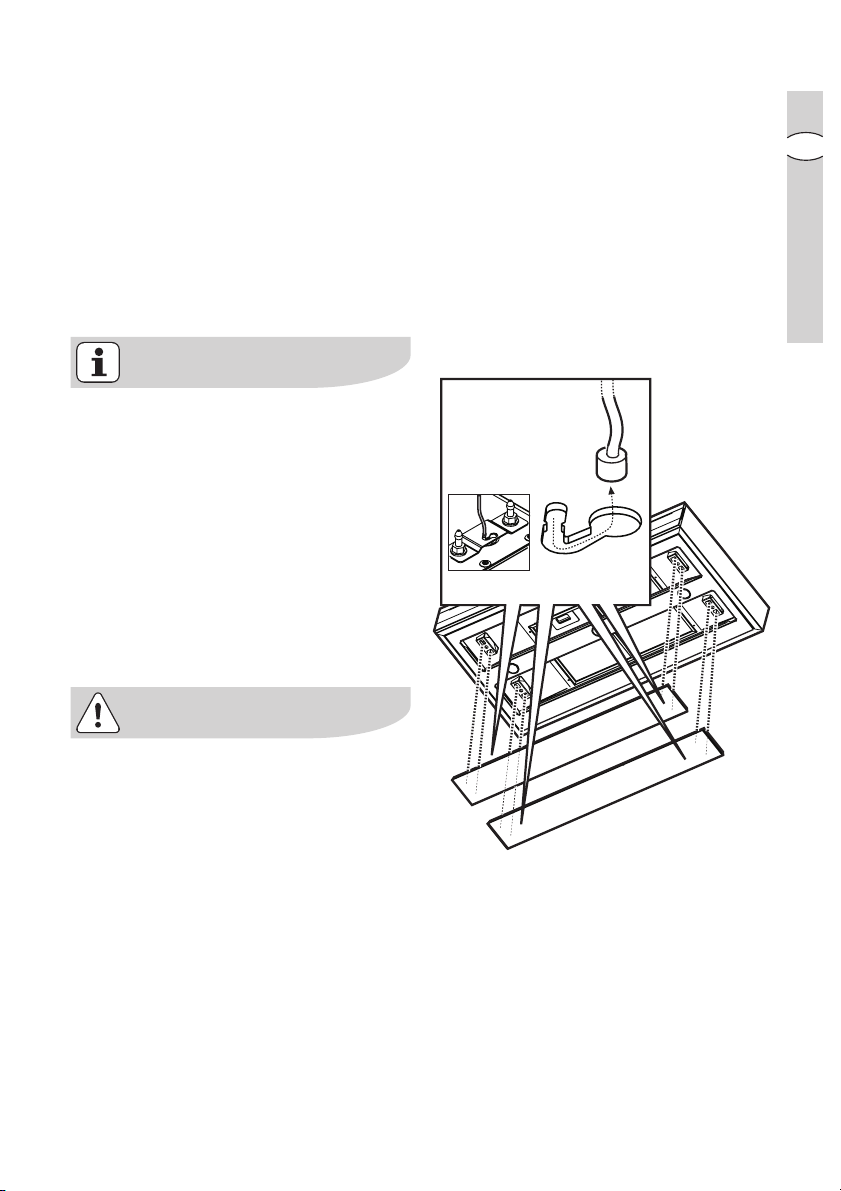
Installing the structural support toInstalling the structural support to
FRONT
6 x Ø 10 + 4 x Ø 6x70
SX
DX
FRONT
E (mm)-180
Installing the structural support to
Installing the structural support toInstalling the structural support to
the cooker hoodthe cooker hood
the cooker hood
the cooker hoodthe cooker hood
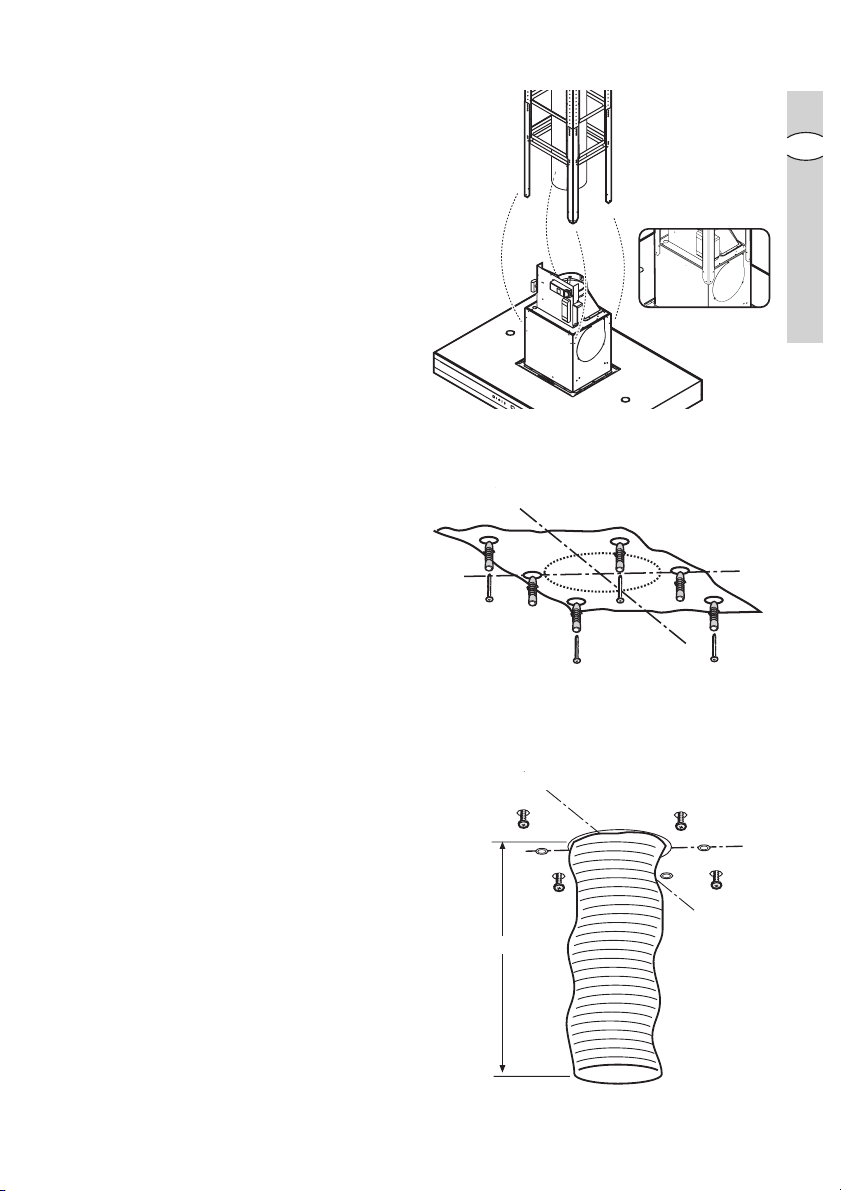
• Fix the cooker hood to the structural
support using 16 screws (4 per
bracket).
Installing the structural support toInstalling the structural support to
Installing the structural support to
Installing the structural support toInstalling the structural support to
the ceilingthe ceiling
the ceiling
the ceilingthe ceiling
• Place the template on the ceiling
directly above the hob (the centre
and sides of the template should be
aligned with the centre and sides of
the hob).
Note: Note:
Note: The side displaying the text
Note: Note:
“FRONT” corresponds to the side
which will house the control panel
once installation is complete.
• Make the holes as indicated on the
template (6 holes for 6 screw
anchors) and partially tighten 4
screws into the screw anchors in the
corners (leave approximately 1 cm
between the head of the screw and
the ceiling).
• Prepare the electrical connection.
Ducted version only:Ducted version only:
•
Ducted version only: Install an
Ducted version only:Ducted version only:
exhaust tube long enough to reach
the outlet ring located above the
cooker hood.
The tube should be fitted to the
ceiling as an exhaust system to expel
fumes outside; the visible part should
be 180 mm shorter than the
structural support (please refer to
measurement
EE
E calculated
EE
previously).
electrolux electrolux
electrolux installation
electrolux electrolux
2323
23
2323
GB
Page 24
2424
X 4!
2 x
Ø6 x 70
F
electr electr
24
2424
oluxolux
electr
olux installation
electr electr
oluxolux
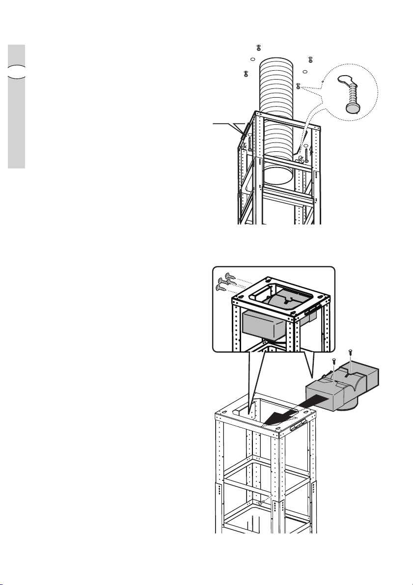
• Install the structure to the ceiling,
onto the 4 pre-tightened screws and
GB
then screw them in firmly.
• Fix it in place using 2 screws.
For the rFor the r
•
For the r
For the rFor the r
ecirecir
culation mode only:culation mode only:
ecir
culation mode only:
ecirecir
culation mode only:culation mode only:
assemble the three parts of the
deflector (central part + 2 extensions)
using 2 screws so that once
assembled, the deflector is the same
width as the structural support.
Fasten the deflector inside the
structural support using 4 screws.
Fit an exhaust tube to the deflector
connection ring. The tube must be
300 mm shorter in length than the
structural support
measurement
(please refer to
EE
E calculated
EE
previously).
• Connect the exhaust tube to the
connection ring above the cooker
hood.
• Carry out the necessary electrical
connection.
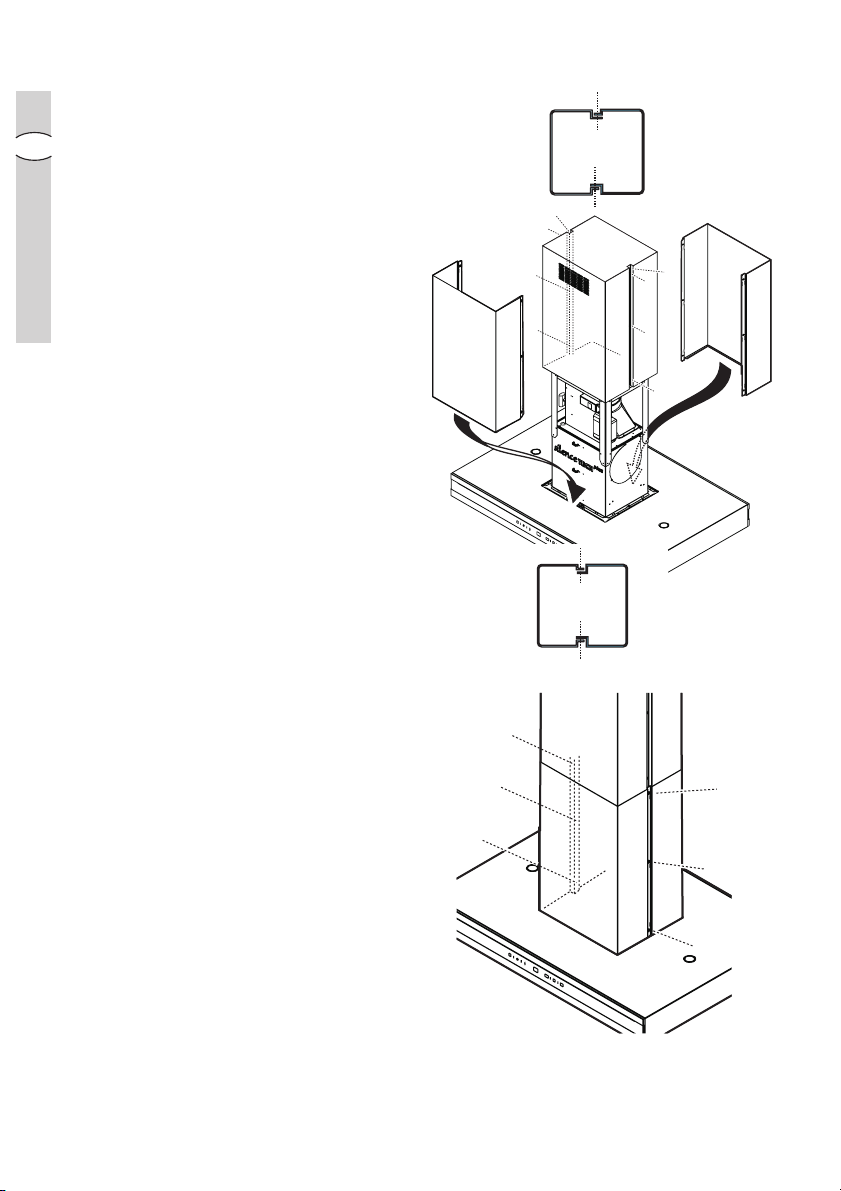
Page 25
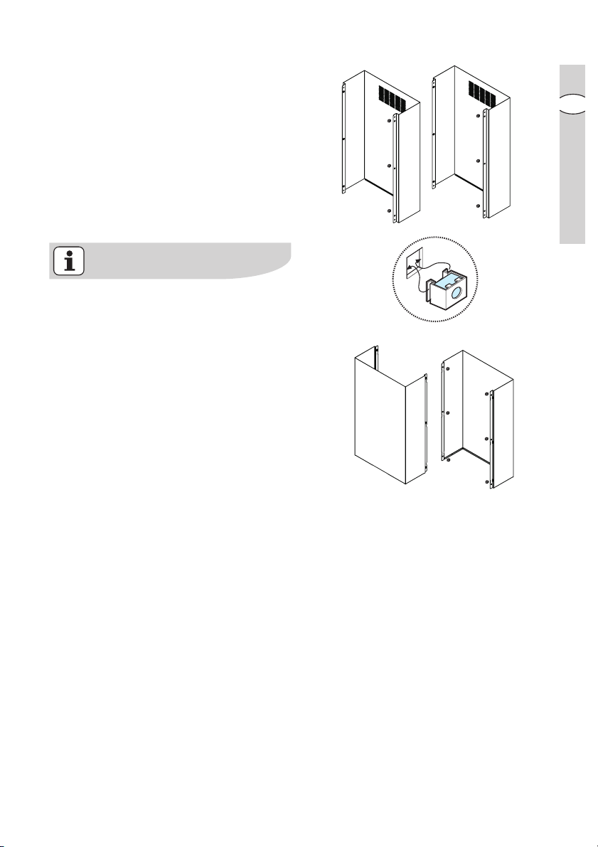
Installing the fluesInstalling the flues
P x 3
R x 6
Q x 3
P
Q
R
S
S x 0
Installing the flues
Installing the fluesInstalling the flues
• Fix the nuts in place with the
couplings both on the upper internal
sections of the flues (P+Q) and on the
lower back section of the flues (R).
• Fix the two upper flue sections (P+Q)
directly onto the structural support of
the cooker hood according to the
assembly diagram (see adjacent
figure).
For the filter version, the upper
sections must be fitted so that the air
recirculation slots are facing upwards.
If you wish to use the cooker hood as
a ducted model, for aesthetic
purposes, the upper flue sections can
be turned upside down to hide the
slots when the lower flue sections are
installed.
electrolux electrolux
electrolux installation
electrolux electrolux
2525
25
2525
GB
Page 26
2626
P
Q
R
S
P
Q
R
S
electr electr
26
2626
oluxolux
electr
olux installation
electr electr
oluxolux
Fix the section in place using 6
screws (3 per side).
GB
• Lift the flues and fix them onto the
structural support using 2 screws (1
per side).
• Install the lower back section of the
flue (R) by resting it on top of the
cooker hood in the correct position
(widen it slightly to allow for an easy
fit onto the upper flue).
• Install the lower front section of the
flue (S) and widen it slightly to allow
for an easy fit onto the upper section.
Fix the section in place using 6
screws (3 per side).
Page 27

• Cover the fixing points with 4
X
X
casings:
The two lower parts may be hooked
on, however the upper parts must be
cut to size and snapped into place.
• Fix the lower flues in place from inside
the cooker hood using 2 screws.
electrolux electrolux
electrolux installation
electrolux electrolux
2727
27
2727
GB
Reattach the grease filters and the
perimeter air suction panels.
Connect the hood to the mains
electricity (wait about 15 seconds, the
time needed to calibrate the electronic
device that controls the functioning of
the hood), and check, finally, that it is
functioning well.
Only for EFOnly for EF
Only for EF
Only for EFOnly for EF
A 90673:A 90673:
A 90673:
A 90673:A 90673:
The charcoal filter saturation indicator is
disabled.
To enable it please read page 10.
Page 28

2828
28
2828
electr electr
electr
electr electr
oluxolux
olux
oluxolux
Bienvenido al mundo ElectrBienvenido al mundo Electr
Bienvenido al mundo Electr
Bienvenido al mundo ElectrBienvenido al mundo Electr
Gracias por elegir un producto
Electrolux de primera clase, el cual
esperamos le proporcione una gran
satisfacción en el futuro. Electrolux
ambiciona ofrecerle una amplia
variedad de productos de calidad que
haga su vida más cómoda. Usted
encontrará algunos ejemplos en la
portada de este manual. Por favor,
tómese unos minutos para estudiar
este manual de modo que pueda
aprovecharse de los beneficios de su
E
nueva máquina. Nosotros prometemos
proporcionarle una experiencia superior
como usuario y mucha tranquilidad.
¡Buena suerte!
oluxolux
olux
oluxolux
Page 29

IndiceIndice
Indice
IndiceIndice
Recomendaciones de seguridad...... 30
Descripción del aparato ................... 33
Funcionamiento de la campana ....... 34
Mantenimiento y cuidado................. 37
Accesorios especiales ..................... 42
Instalación ....................................... 43
electrolux electrolux
electrolux indice
electrolux electrolux
2929
29
2929
E
En este manual se utiliza los siguientes simbolos :
Informaciones importantes que corresponden a la seguridad personal e
informaciones para evitar daños al aparato.
Informaciones generales y consejos :
Informaciones sobre la conservación ambiental.
Page 30

3030
electr electr
30
3030
oluxolux
electr
olux recomendaciones de seguridad
electr electr
oluxolux
Recomendaciones de seguridad
para el usuariopara el usuario
para el usuario
para el usuariopara el usuario
• Se recomienda no dejar los fuegos
encendidos sin cubrir, ya que el
excesivo calor dañaría el aparato. En
caso de cocinas de gas, gasóleo o
carbón, evitar absolutamente las
llamas libres.
E
• De colocarse una freidora encima de
la cocina o del plano de
cocción, mantenerla bajo control.
• El aceite que contiene la freidora
podría incendiarse espontáneamente
a causa de un exceso de temperatura.
• El riesgo de autocombustión aumen-
ta si se utiliza aceite sucio.
• Tener siempre presente que el
exceso de temperatura puede ser
causa de incendio.
No cocinar a la llama (flambé) bajo laNo cocinar a la llama (flambé) bajo la
•
No cocinar a la llama (flambé) bajo la
No cocinar a la llama (flambé) bajo laNo cocinar a la llama (flambé) bajo la
encimera.encimera.
encimera.
encimera.encimera.
Para rPara r
•
•
ealizar cualquier operación enealizar cualquier operación en
Para r
ealizar cualquier operación en
Para rPara r
ealizar cualquier operación enealizar cualquier operación en
la campana, la campana,
la campana, aun la simple
la campana, la campana,
sustitución de la bombilla,
desconectar el aparato de ladesconectar el aparato de la
desconectar el aparato de la
desconectar el aparato de ladesconectar el aparato de la
alimentación eléctrica alimentación eléctrica
alimentación eléctrica (extraer los
alimentación eléctrica alimentación eléctrica
fusibles de tapón del portafusibles o
desconectar el interruptor
automático).
Es importante rEs importante r
Es importante r
Es importante rEs importante r
de limpieza y sustitución del filtrde limpieza y sustitución del filtr
de limpieza y sustitución del filtr
de limpieza y sustitución del filtrde limpieza y sustitución del filtr
De no hacerse así, la grasaDe no hacerse así, la grasa
De no hacerse así, la grasa
De no hacerse así, la grasaDe no hacerse así, la grasa
depositada puede causar un incen-depositada puede causar un incen-
depositada puede causar un incen-
depositada puede causar un incen-depositada puede causar un incen-
dio.dio.
dio.
dio.dio.
espetar los intervalosespetar los intervalos
espetar los intervalos
espetar los intervalosespetar los intervalos
o.o.
o.
o.o.
Este aparato lleva el marcado CE en
conformidad con la Directiva 2002/96/
EC del Parlamento Europeo y del
Consejo sobre residuos de aparatos
eléctricos y electrónicos (RAEE).
La correcta eliminación de este
producto evita consecuencias
negativas para el medioambiente y la
salud.
El símbolo
en el producto o en los
documentos que se incluyen con el
producto, indica que no se puede
tratar como residuo doméstico. Es
necesario entregarlo en un punto de
recogida para reciclar aparatos
eléctricos y electrónicos.
Deséchelo con arreglo a las normas
medioambientales para eliminación de
residuos.
Para obtener información más
detallada sobre el tratamiento,
recuperación y reciclaje de este
producto, póngase en contacto con el
ayuntamiento, con el servicio de
eliminación de residuos urbanos o la
tienda donde adquirió el producto.
Page 31

electroluxelectrolux
electrolux
electroluxelectrolux
recomendaciones de seguridad
3131
31
3131
para el montador de mueblespara el montador de muebles
para el montador de muebles
para el montador de mueblespara el montador de muebles
• En caso de funcionamiento de
aspiración, salida libre, el tubo de
descarga debe tener el mismo
diámetro del anillo de conexión.
Atención: tubo no suministrado, seAtención: tubo no suministrado, se
Atención: tubo no suministrado, se
Atención: tubo no suministrado, seAtención: tubo no suministrado, se
puede adquirir separadamente.puede adquirir separadamente.
puede adquirir separadamente.
puede adquirir separadamente.puede adquirir separadamente.
• Al montar la campana, respetar las
siguientes distancias mínimas desde
el borde superior de los quemadores
o placas:
cocinas eléctricascocinas eléctricas
cocinas eléctricas
cocinas eléctricascocinas eléctricas
cocinas de gascocinas de gas
cocinas de gas
cocinas de gascocinas de gas
500 mm500 mm
500 mm
500 mm500 mm
650 mm650 mm
650 mm
650 mm650 mm
Si las instrucciones para la instalación
del dispositivo para cocinar con gas
especifican una distancia mayor, hay
que tenerlo en consideración.
• El decreto sobre equipos de
combustión admite, para estos
ambientes, una depresión máxima de
0,04 mbar.
• La salida de aire no debe conectarse
a chimeneas ni a conductos de
evacuación de gases de combustión.
No se debe bajo ninguna
circunstancia conectar la salida de
aire a un conducto que sirva para
ventilar habitaciones donde funcionen
aparatos de combustión.
• Ante la posibilidad de conexión de la
salida de aire a una chimenea o
conducto de evacuación de gases de
combustión fuera de servicio, solicite
la autorización del organismo de
control competente. Para la
conducción de la salida de aire,
atengase a las prescripciones de las
autoridades competentes.
• Si el aparato se utiliza para
funcionamiento de aspiración,
preparar un orificio de ventilación de
diámetro suficiente, prácticamente
igual al de descarga.
• Las disposiciones nacionales y
locales de construcción, imponen
unas serie de normas para la
instalación conjunta en la misma
habitación de una campana y otros
aparatos de combustión conectados
a chimeneas (tales como estufas de
carbón, gasóleo o gas).
• El uso conjunto de campanas y
aparatos de combustión conectados
a chimeneas tiene garantía de
seguridad sólo si la habitación y/o
piso (combinación aire/ambiente)
reciben ventilación del exterior a
través de un orificio adecuado
(aproximadamente 500-600 cm
2
),
para evitar que se genere una
depresión durante el funcionamiento
de la campana.
• En caso de dudas, dirigirse al
organismo de control competente o
al departamento de obras de
construcción.
• En los ambientes donde haya
aparatos de combustión instalados,
se aplica la regla : “medida del orificio
de salida = a la medida del orificio de
ventilación” o sea un orificio de 500600 cm
2
, por lo que un orificio mayor
puede perjudicar el funcionamiento
de la campana.
• El uso de la campana en el modo de
recirculación resulta sencillo y seguro,
no haciendo falta respetar las
prescripciones anteriormente dichas.
• El funcionamiento de la campana en
modo extractor resultará óptimo
E
Page 32

3232
electr electr
32
3232
oluxolux
electr
olux recomendaciones de seguridad
electr electr
oluxolux
siempre que se respeten la siguientes
condiciones :
- montar el tubo de salida con
tramos cortos y rectos
- realizar el menor número de codos
posible
- no colocar los tubos en ángulos
agudos, sino ligeramente
arqueados
- si es posible, utilizar tubo de
diámetro grande (mínimo el mismo
diámetro del anillo de conexión).
• La no observación de estas reglas
E
básicas provocará drásticas
disminuciones de rendimiento y un
funcionamiento más ruidoso.
Page 33

Descripción del aparato
• La campana se entrega en modo
extractor, pudiendo utilizarla también
en modo de recirculación, instalando
para ello un filtro de carbón activado
(accesorio especial).
• Para esta función, es necesario un
filtro de carbón activo original (véase
el párrafo «Accesorios especiales»).
Ùnicamente por EFÙnicamente por EF
•
Ùnicamente por EF
Ùnicamente por EFÙnicamente por EF
campana incluye 1 filtro de carbón.
Funcionamiento extractorFuncionamiento extractor
Funcionamiento extractor
Funcionamiento extractorFuncionamiento extractor
• El aire se extrae al exterior mediante
un tubo conectado al anillo de
conexión
..
.
..
• Para un mejor rendimiento , el tubo
tiene que tener el mismo diámetro
que el orificio de salida.
A 90673:A 90673:
A 90673: esta
A 90673:A 90673:
electrolux electrolux
electrolux descripción del aparato
electrolux electrolux
anillo de conexiónanillo de conexión
anillo de conexión
anillo de conexiónanillo de conexión
3333
33
3333
E
Funcionamiento de rFuncionamiento de r
Funcionamiento de r
Funcionamiento de rFuncionamiento de r
ecirecir
ecir
ecirecir
culaciónculación
culación
culaciónculación
• El filtro de carbón filtra el aire que
pasa de nuevo a la cocina a través
de la rejilla superior de la chimenea
de aspiración.
• Para esta función, es necesario un
filtro de carbón activo original (véase
el párrafo «Accesorios especiales»).
Page 34

3434
electr electr
34
3434
oluxolux
electr
olux funcionamiento de la campana
electr electr
oluxolux
Funcionamiento de la campana
• La campana está dotada de velocidad regulable.
Se aconseja activar la campana unos minutos antes de comenzar la cocción y
dejarla en marcha hasta 15 minutos después de terminarla para eliminar completamente los olores.
• La campana puede comandarse también mediante el panel de mandos o el
control remoto (el control remoto es un accesorio y debe ordenarse
separadamente, véase párrafo “Accesorios especiales”).
••
VV
entilación adecuadaentilación adecuada
•
V
entilación adecuada: Para que la campana actúe adecuadamente deberá
••
VV
entilación adecuadaentilación adecuada
mantener las ventanas de la cocina cerradas. En su lugar abra la ventana de
E
una habitación adyacente.
• Los interruptores se encuentran en el frontal del aparato :
Page 35

electrolux electrolux
electrolux funcionamiento de la campana
electrolux electrolux
3535
35
3535
Modelo EFModelo EF
Modelo EF
Modelo EFModelo EF
1.1.
Boton ON/OFF luz:Boton ON/OFF luz:
1.
Boton ON/OFF luz: pulsarlo brevemente para activar la iluminación del plano
1.1.
Boton ON/OFF luz:Boton ON/OFF luz:
A 9673 - 90673A 9673 - 90673
A 9673 - 90673
A 9673 - 90673A 9673 - 90673
b
a
123 456
7
de cocción, mantenerlo pulsado más de 2 segundos para encender las luces
superiores.
22
Botón principalBotón principal
2.
Botón principal se enciende y se apaga la campana.
22
Botón principalBotón principal
Mantenga apretado durante menos de 1,5 segundos, la campana se pone en
posición de espera (
Stand byStand by
Stand by) ( el
Stand byStand by
puntopunto
“a”“a”
punto
“a” está encendido).
puntopunto
“a”“a”
Mantenga apretado durante mas de 1,5 segundos, la campana se apagará
OFFOFF
(
OFF), TODOS los controles (excepto el que enciende la luz) están
OFFOFF
desconectados ( el display está completamente apagado).
Vuelva a apretar de nuevo durante mas de 1,5 segundos para poner de nuevo
la campana en posición de stand-by.
3.3.
Botón de rBotón de r
3.
Botón de r
3.3.
Botón de rBotón de r
einiciación saturación filtreiniciación saturación filtr
einiciación saturación filtr
einiciación saturación filtreiniciación saturación filtr
os: os:
os: véase el texto relativo en las paginas
os: os:
siguientes.
44
Arranca y selecciona la velocidad del motor 1-2-3-1-2...Arranca y selecciona la velocidad del motor 1-2-3-1-2...
4.
Arranca y selecciona la velocidad del motor 1-2-3-1-2...
44
Arranca y selecciona la velocidad del motor 1-2-3-1-2...Arranca y selecciona la velocidad del motor 1-2-3-1-2...
55
Se enciende y se apaga la velocidad intensiva. Se enciende y se apaga la velocidad intensiva.
5.
Se enciende y se apaga la velocidad intensiva. La velocidad intensiva
55
Se enciende y se apaga la velocidad intensiva. Se enciende y se apaga la velocidad intensiva.
funciona durante 5 minutos: Si la campana está encendida cuando la
velocidad intensiva está activada, la campana transcurridos 5 minutos vuelve a
la velocidad inicial.
Si la campana está apagada cuando la velocidad intensiva está activada, la
campana transcurridos 5 minutos se apaga automáticameante.
La letra
PP
P aparece en el display y el tiempo que queda ( el
PP
puntopunto
punto
puntopunto
“b”“b”
“b”
“b”“b”
parpadea), hasta el final el sistema emite una señal acústica.
66
TT
imer ON/OFF: imer ON/OFF:
6.
T
imer ON/OFF: mide el tiempo de las velocidades ( el
66
TT
imer ON/OFF: imer ON/OFF:
puntopunto
punto
puntopunto
“a”“a”
“a” parpadea)y
“a”“a”
entonces la campana se apaga:
1° velocidad 20 minutos
2° velocidad 15 minutos
3° velocidad 10 minutos
El display muestra el tiempo que queda para el final, el sistema emite una
señal acustica. Manteniendo apretado el botón de nuevo finaliza la función.
77
DisplayDisplay
7.
Display
77
DisplayDisplay
E
Si la campana o los demás componentes no funcionaran bien: desconecte la
corriente electrica durante al menos 5 segundos, despues vuelva a encender la
campana. Espere al menos 15 segundos para comprobar que la campana está
funcionando correctamente.
Page 36

3636
36
3636
electr electr
oluxolux
electr
olux funcionamiento de la campana
electr electr
oluxolux
Dispositivo de contrDispositivo de contr
Dispositivo de contr
Dispositivo de contrDispositivo de contr
antigrasa y para el filtrantigrasa y para el filtr
antigrasa y para el filtr
antigrasa y para el filtrantigrasa y para el filtr
activo.activo.
activo.
activo.activo.
ol para el filtrol para el filtr
ol para el filtr
ol para el filtrol para el filtr
o al carbóno al carbón
o al carbón
o al carbóno al carbón
Esta campana posee un dispositivo
que avisa cuando hay que limpiar el
filtro antigrasa o cuando hay que
cambiar el filtro al carbón activo [para la
función de recirculación con el filtro al
carbón activo]
Esta campana viene de fábrica sin el
E
filtro al carbón activo
EFEF
A 9673)A 9673)
EF
A 9673), por lo tanto el aviso de
EFEF
A 9673)A 9673)
(Ùnicamente por(Ùnicamente por
(Ùnicamente por
(Ùnicamente por(Ùnicamente por
saturación no está activo.
Si la campana viene con el filtro al
carbón activo se puede poner en
funcionamiento esta función que avisa
de la saturación de la siguiente manera:
Coloque la campana en «
OFFOFF
OFF».
OFFOFF
hay que pulsar a la vez los botones
44
4 durante 3 segundos.
44
Al principio se illumina solamente el
PILOTO
FF
F que avisa del filtro antigrasa,
FF
e inmediatamente despues se
enciende tambien el PILOTO
avisa del filtro al carbón activo y de esa
manera se pone en marcha la función
que avisa de la saturación.
Para desactivarla pulse otra vez los
33
botones
ilumine el PILOTO
44
3 y
4 a la vez hasta que se
33
44
CC
C que avisa del filtro
CC
al carbón.
CC
C que
CC
oo
PILOTO [F] que avisa del filtro
o
oo
antigrasa.
El PILOTO
FF
F se ilumina cuando hay que
FF
limpiar el filtro antigrasa. Esto se
produce cuando hayan pasado
aproximadamente 40 horas de uso.
Lea las instrucciones sobre el
mantenimiento del filtro antigrasa.
PILOTO [C] que avisa del filtro al
carbón activo
El PILOTO
CC
C se ilumina cuando hay
CC
que limpiar el filtro al carbón activo.
Esto se produce cuando hayan pasado
160 horas de uso.
Lea las instrucciones para cambiar el
filtro al carbón.
Resetear la señal de saturación
Despues de limpiar o volver a colocar
33
3 y
33
los filtros , apriete el botón
segundos hasta que el filtro antigrasa
PILOTO
PILOTO
FF
F o el filtro al carbón activo
FF
CC
C dejen de parpadear.
CC
33
3 durante 3
33
Page 37

Mantenimiento y cuidado
x 4
electrolux electrolux
electrolux mantenimiento y cuidado
electrolux electrolux
3737
37
3737
Antes de rAntes de r
•
Antes de r
Antes de rAntes de r
na de la alimentación eléctrica.na de la alimentación eléctrica.
na de la alimentación eléctrica.
na de la alimentación eléctrica.na de la alimentación eléctrica.
Paneles de aspiraciónPaneles de aspiración
Paneles de aspiración
Paneles de aspiraciónPaneles de aspiración
ealizar cualquier trabajo de mantenimiento, desconectar la campa-ealizar cualquier trabajo de mantenimiento, desconectar la campa-
ealizar cualquier trabajo de mantenimiento, desconectar la campa-
ealizar cualquier trabajo de mantenimiento, desconectar la campa-ealizar cualquier trabajo de mantenimiento, desconectar la campa-
Para acceder a los filtros antigrasa, es
necesario remover previamente los
paneles de aspiración perimetral.
Los paneles de aspiración perimetral
están fijados a la campana mediante un
perper
nosnos
sistema de
engancheenganche
enganche: es suficiente tirar hacia
engancheenganche
per
perper
nos y
nosnos
muelles demuelles de
muelles de
muelles demuelles de
afuera con decisión y desengancharlos
cable de rcable de r
del
cable de r
cable de rcable de r
etención.etención.
etención.
etención.etención.
Los paneles de aspiración tienen que
limpiarse con la misma frecuencia que
la de los filtros antigrasa (para la
limpieza véase el apartado “Limpieza”
en las páginas siguientes).
E
Al volver a colocar los paneles de
aspiración perimetral, SIEMPRE hay
que enganchar los cables de retención.
Controlar que los paneles queden
efectivamente fijados a la campana
(enganche a presión).
Page 38

3838
electr electr
38
3838
FiltrFiltr
Filtr
FiltrFiltr
oluxolux
electr
olux mantenimiento y cuidado
electr electr
oluxolux
o grasao grasa
o grasa
o grasao grasa
• El propósito del filtro antigrasas es la
absorción de partículas de grasa que
se forman durante la cocción y éste
debe utilizarse siempre, sea en modo
extractor al exterior o en modo de
recirculación interna.
El filtro antigrasa metálico tiene que
extraerse y lavarse a mano o en el
lavavajillas cada cuatro semanas.
E
Extracción del filtrExtracción del filtr
Extracción del filtr
Extracción del filtrExtracción del filtr
metálicometálico
metálico
metálicometálico
o antigrasao antigrasa
o antigrasa
o antigrasao antigrasa
· Accionar la manilla y desenganchar el
filtro hacia abajo.
Lavado a manoLavado a mano
Lavado a mano
Lavado a manoLavado a mano
Sumergir el filtro antigrasa en agua
caliente con un detergente
desengrasante y dejarlo sumergido
durante una media hora antes de
aclararlo con abundante agua
caliente. Si es necesario, repetir el
procedimiento. Volver a montar el
filtro antigrasa cuando esté seco.
LavavajillasLavavajillas
Lavavajillas
LavavajillasLavavajillas
Poner el filtro antigrasa en el
lavavajillas. Seleccionar el programa
de lavado más enérgico y la temperatura más elevada (al menos 65°C). Si
es necesario, repetir el
procedimiento. Montar el filtro
cuando esté seco.
Con el lavado en lavavajillas, elCon el lavado en lavavajillas, el
Con el lavado en lavavajillas, el
Con el lavado en lavavajillas, elCon el lavado en lavavajillas, el
filtrfiltr
o antigrasa puedeo antigrasa puede
filtr
o antigrasa puede
filtrfiltr
o antigrasa puedeo antigrasa puede
descolordescolor
descolor
descolordescolor
pierpier
pier
pierpier
earse ligeramente perearse ligeramente per
earse ligeramente per
earse ligeramente perearse ligeramente per
de su eficacia.de su eficacia.
de su eficacia.
de su eficacia.de su eficacia.
o noo no
o no
o noo no
• Limpiar el alojamiento interior del filtro
exclusivamente con una solución de
detergente y agua caliente (no utilizar
detergentes cáusticos, polvo abrasivo o cepillos).
Page 39

FiltrFiltr
o de carbón activadoo de carbón activado
Filtr
o de carbón activado
FiltrFiltr
o de carbón activadoo de carbón activado
• El filtro de carbón activado solo se
utiliza para la función de recirculación.
• Instalar siempre un filtro de carbón
activado original. (véase el párrafo
«Accesorios especiales»).
electrolux electrolux
electrolux mantenimiento y cuidado
electrolux electrolux
3939
39
3939
Limpieza\sustitución del filtrLimpieza\sustitución del filtr
•
Limpieza\sustitución del filtr
Limpieza\sustitución del filtrLimpieza\sustitución del filtr
carbóncarbón
carbón
carbóncarbón
o deo de
o de
o deo de
Al contrario de otros tipos, el filtro de
carbón, el filtro al carbón LONGLIFE
se puede limpiar y volverlo a poner en
la campana.
Se aconseja, en un uso normal,
limpiar el filtro cada dos meses. El
lavado en lavavajillas es la mejor
manera para limpiarlo.Use un detergente normal y seleccione la temperatura más alta (65°C). Lave el filtro
por separado para evitar que se
peguen restos de comida y puedan
causar mal olor. Para poderlo usar
otra vez, métalo en el horno durante
10 minutos a una temperatura
máxima de 100°C.
Se aconseja cambiar el filtro al
carbón después de 3 años
aproximadamente porque la
capacidad de absorción de los olores
podría disminuir.
MontajeMontaje
•
Montaje
MontajeMontaje
Posicione el filtro al carbón en el
interior de la campana a cobertura
de la rejilla de protección del motor.
Fije el filtro con 2 pomos laterales.
Para el desmontajePara el desmontaje
•
Para el desmontaje, efectuar las
Para el desmontajePara el desmontaje
operaciones anteriores en orden
inverso.
• Cuando se vaya a pedir un filtro de
recambio, indicar el modelo y el
número de producto. Estos datos
pueden leerse en la placa de
características colocada en la parte
interna del aparato.
• El filtro de carbón activado puede
solicitarse al servicio de asistencia
técnica.
E
Page 40

4040
electr electr
40
4040
AtenciónAtención
Atención
AtenciónAtención
oluxolux
electr
olux mantenimiento y cuidado
electr electr
oluxolux
• De no observarse las instrucciones
dadas para limpiar el aparato y
sustituir el filtro, puede producirse un
incendio. El fabricante recomienda
leerlas y respetarlas atentamente.
• El fabricante no se hace responsable
por los daños al motor o los incendios provocados en el aparato
debido a intervenciones de manteni-
E
miento incorrectas o al incumplimiento de las normas de seguridad
proporcionadas.
Sustitución de la bombillasSustitución de la bombillas
Sustitución de la bombillas
Sustitución de la bombillasSustitución de la bombillas
••
Desconectar el aparato de laDesconectar el aparato de la
•
Desconectar el aparato de la
••
Desconectar el aparato de laDesconectar el aparato de la
alimentación eléctrica.alimentación eléctrica.
alimentación eléctrica.
alimentación eléctrica.alimentación eléctrica.
••
Antes de tocar las bombillasAntes de tocar las bombillas
•
Antes de tocar las bombillas
••
Antes de tocar las bombillasAntes de tocar las bombillas
asegurarse que esten frias.asegurarse que esten frias.
asegurarse que esten frias.
asegurarse que esten frias.asegurarse que esten frias.
• Cambie la bombilla antigua por una
nueva del mismo tipo.
• Si la bombilla no se enciende, antes
de llamar al servicio de asistencia
técnica, controlar que esté bien
ajustada.
20W max20W max
20W max
20W max20W max
GU4 - 12 V - Ø 35mm - 30° - Dichroic
Page 41

LimpiezaLimpieza
Limpieza
LimpiezaLimpieza
• Atención : antes de limpiar la campana, desconectarla de la alimentación
eléctrica. No introducir objetos con
punta en la rejilla de protección del
motor.
• Lavar las partes externas con una
solución detergente suave.
Evitar el uso de detergentes cáusticos, cepillos y polvos abrasivos.
• Limpiar el panel de los interruptores y
la rejilla del filtro únicamente con un
paño húmedo y detergentes suaves.
• Limpiar todas las partes de plástico
con un paño suave rociado con agua
tibia y jabón neutro.
• Es importante respetar los intervalos
de limpieza y de sustitución del filtro.
De no hacerse así, la grasa depositada puede causar un incendio.
electrolux electrolux
electrolux mantenimiento y cuidado
electrolux electrolux
4141
41
4141
E
Page 42

4242
electr electr
42
4242
oluxolux
electr
olux accesorios especiales
electr electr
oluxolux
Accesorios especiales
Filtro de carbón activado
Type 967
ContrContr
ol rol r
ol r
ol rol r
emotoemoto
emoto
emotoemoto
E
Contr
ContrContr
RM 6940
Page 43

Instalación
Características técnicasCaracterísticas técnicas
Características técnicas
Características técnicasCaracterísticas técnicas
EFEF
A 9673 (EFA 9673 (EF
EF
A 9673 (EF
EFEF
A 9673 (EFA 9673 (EF
Dimensiones (en cm):Dimensiones (en cm):
Dimensiones (en cm):
Dimensiones (en cm):Dimensiones (en cm):
Altura (Func. extractor): 89,5 ÷ 118,5
Altura (Func. de recirculación): 89,5 ÷ 129,5
Ancho: 99,8
Profundidad: 70
Consumo total:Consumo total:
Consumo total:
Consumo total:Consumo total:
Absorción de motor : 250 W
Iluminación: 5 x 20 W
Longitud de cable:Longitud de cable:
Longitud de cable:
Longitud de cable:Longitud de cable:
Conexión eléctrica:Conexión eléctrica:
Conexión eléctrica:
Conexión eléctrica:Conexión eléctrica:
Accesorios/Piezas de montaje incluidasAccesorios/Piezas de montaje incluidas
Accesorios/Piezas de montaje incluidas
Accesorios/Piezas de montaje incluidasAccesorios/Piezas de montaje incluidas
350 W350 W
350 W
350 W350 W
150 cm150 cm
150 cm
150 cm150 cm
220-240 V220-240 V
220-240 V
220-240 V220-240 V
electrolux electrolux
electrolux instalación
electrolux electrolux
A 90673)A 90673)
A 90673)
A 90673)A 90673)
4343
43
4343
E
1 llave para tornillos torx
12 tuercas
6 tornillos 6 x 70 mm
6 bulones Ø 10 mm
12 tornillos 4 x 7 mm
58 tornillos 3.5 x 9.5
1 deflector (con prolongador)
Page 44

4444
electr electr
44
4444
oluxolux
electr
olux instalación
electr electr
oluxolux
Conexión eléctrica
Recomendaciones para el electricistaRecomendaciones para el electricista
Recomendaciones para el electricista
Recomendaciones para el electricistaRecomendaciones para el electricista
Antes de conectar el aparato, controlar
que la tensión de la red y la indicada en
la placa de características sean iguales.
Si el aparato es conectado a un
enchufe, se puede conectar a cualquier
toma accesible que esté instalada
según normas. Si fuera necesario
E
realizar una conexión fija, confiar el
trabajo exclusivamente a un electricista
autorizado por la compañía de
electricidad competente. Para la
instalación se requiere un interruptor
bipolar con una separación mínima de
los contactos de 3 mm.
El fabricante no asume responsabilidad
alguna por anomalías que deriven de la
no observación de las indicaciones
dadas.
La conexión fija debe ser realizada
exclusivamente por un electricista
autorizado.
Page 45

InstalaciónInstalación
Instalación
InstalaciónInstalación
electrolux electrolux
electrolux instalación
electrolux electrolux
4545
45
4545
Antes de rAntes de r
Antes de r
Antes de rAntes de r
la rla r
ed eléctrica.ed eléctrica.
la r
ed eléctrica.
la rla r
ed eléctrica.ed eléctrica.
ealizar la instalación asegurarse que el aparato sea desconectado deealizar la instalación asegurarse que el aparato sea desconectado de
ealizar la instalación asegurarse que el aparato sea desconectado de
ealizar la instalación asegurarse que el aparato sea desconectado deealizar la instalación asegurarse que el aparato sea desconectado de
La campana posee espigas de fijación que se adaptan a la mayor parte de
paredes y techos. No obstante, es necesario consultar a un técnico especializado
para confirmar la idoneidad de los materiales de acuerdo con el tipo de pared o
techo. La pared o techo debe ser suficientemente fuerte como para sostener el
peso de la campana.
Desmontar los paneles de aspiración perimetral y los filtros antigrasa.
Antes de la instalación:Antes de la instalación:
Antes de la instalación:
Antes de la instalación:Antes de la instalación:
El cañón de la chimenea de la campana se suministra parcialmente preinstalado.
Las partes principales que componen el cañón de la chimenea son:
• el cañón superior
• las abrazaderas de extensión del cañón
• las abrazaderas de refuerzo
2 superiores
1 inferior
C2C2
C2
C2C2
Descripción del cañón superior A:
AA
A (1x).
AA
BB
B (4x)
BB
CC
C (3x) de las cuales hay:
CC
C1C1
- -
C1
- de las cuales 1 está previamente ensamblada
C1C1
- -
Punto de enganche / fijación
del cañón de chimenea al
techo
Puntos de fijación de las
abrazaderas de extensión
BB
B
BB
E
Abrazaderas de refuerzo
C1C1
C1
C1C1
Puntos de fijación de las 2
abrazaderas de refuerzo
C1C1
C1
C1C1
Page 46

4646
46
4646
electr electr
oluxolux
electr
olux instalación
electr electr
oluxolux
Descripción de las abrazaderas de rDescripción de las abrazaderas de r
Descripción de las abrazaderas de r
Descripción de las abrazaderas de rDescripción de las abrazaderas de r
efuerzo C1 y C2:efuerzo C1 y C2:
efuerzo C1 y C2:
efuerzo C1 y C2:efuerzo C1 y C2:
abrazaderas de refuerzo
C1C1
C1 (superior e intermedia)
C1C1
abrazadera de
refuerzo
E
Descripción de las abrazaderas de extensión Descripción de las abrazaderas de extensión
Descripción de las abrazaderas de extensión B
Descripción de las abrazaderas de extensión Descripción de las abrazaderas de extensión
C2 C2
C2 (inferior)
C2 C2
::
:
::
Puntos de fijación al
cañón superior
Puntos de fijación
de la abrazadera
de refuerzo inferior
C2C2
C2
C2C2
Puntos de fijación
de la abrazadera a
la campana
Page 47

PrPr
L
E
E (mm)= L- 355
eparación de la estructura deeparación de la estructura de
Pr
eparación de la estructura de
PrPr
eparación de la estructura deeparación de la estructura de
soportesoporte
soporte
soportesoporte
Antes de ensamblar el cañón, calcule la
extensión que deberá tener el mismo.
Para ello, utilice la fórmula del dibujo (al
costado).
Anote en este manual la medida
E,E,
E, la
E,E,
cual servirá como referencia para
calcular la longitud del tubo de
descarga.
La dimensión
LL
L deberá respetar las
LL
distancias mínimas de la encimera
indicadas en el párrafo
“Recomendaciones de seguridad –“Recomendaciones de seguridad –
“Recomendaciones de seguridad –
“Recomendaciones de seguridad –“Recomendaciones de seguridad –
para el montador de muebles”.para el montador de muebles”.
para el montador de muebles”.
para el montador de muebles”.para el montador de muebles”.
electrolux electrolux
electrolux instalación
electrolux electrolux
4747
47
4747
E
• Instale las abrazaderas de extensión
AA
A con 4 tornillos para cada una, para
AA
extender el cañón a la dimensión
EE
E
EE
calculada.
Page 48

4848
48
4848
electr electr
oluxolux
electr
olux instalación
electr electr
oluxolux
Para extensiones del cañón de chimenea (ver la medida
mente):
inferiorinferior
-
-
-
Utilice 8 tornillos para la fijación de cada abrazadera de refuerzo.
Nota: Nota:
Nota: Una de las dos abrazaderas
Nota: Nota:
E
es a 690 mm:es a 690 mm:
inferior
es a 690 mm: para esta extensión se prevé una sola abrazadera (
inferiorinferior
es a 690 mm:es a 690 mm:
generalmente ya está fijada en su posición.
comprcompr
endidas entrendidas entr
compr
endidas entr
comprcompr
endidas entrendidas entr
superiorsuperior
superior
superiorsuperior
x C1+1 x C2).x C1+1 x C2).
x C1+1 x C2).
x C1+1 x C2).x C1+1 x C2).
es a 800 mm: es a 800 mm:
es a 800 mm: Instale todas las abrazaderas de refuerzo disponibles
es a 800 mm: es a 800 mm:
e 690 mm y 795 mm: e 690 mm y 795 mm:
e 690 mm y 795 mm: instale ambas abrazaderas
e 690 mm y 795 mm: e 690 mm y 795 mm:
C1C1
C1 generalmente se suministra ya montada.
C1C1
EE
E calculada precedente-
EE
C1
C1C1
C1.
C1C1
C1C1
C1),
C1C1
(2(2
(2
(2(2
C2
C1
Page 49

Montaje de la estructura deMontaje de la estructura de
FRONT
6 x Ø 10 + 4 x Ø 6x70
SX
DX
FRONT
E (mm)-180
Montaje de la estructura de
Montaje de la estructura deMontaje de la estructura de
soporte a la campanasoporte a la campana
soporte a la campana
soporte a la campanasoporte a la campana
• Fijar la campana a la estructura de
soporte con 16 tornillos (4 por cada
perfil de sujeción).
Instalación de la estructura deInstalación de la estructura de
Instalación de la estructura de
Instalación de la estructura deInstalación de la estructura de
soporte en el techosoporte en el techo
soporte en el techo
soporte en el techosoporte en el techo
• Presentar la plantilla directamente en
el techo, verticalmente alineada con
el plano de cocción (el centro y los
lados de la plantilla deben estar
alineados con el centro y los lados
del plano de cocción).
NotaNota
Nota: el lado donde figura escrito
NotaNota
“FRONT” es en el que estarán
ubicados los botones cuando la
instalación se finalice.
• Perforar según las marcas de la
plantilla (6 agujeros para 6 tacos) y
enroscar parcialmente los 4 tornillos
en los tacos de las esquinas (dejar
aproximadamente 1 cm entre la
cabeza del tornillo y el techo).
• Efectuar la conexión eléctrica.
• Sólo para la versión aspirante: montar
un tubo de salida lo suficientemente
largo para llegar hasta el anillo de
salida situado encima de la campana.
En el techo, el tubo debe ser
acoplado a un sistema de
evacuación al exterior, la parte que
está a la vista debe ser 180 mm más
corta de la estructura de soporte
la medida
EE
E calculada precedente-
EE
mente).
(ver
electrolux electrolux
electrolux instalación
electrolux electrolux
4949
49
4949
E
Page 50

5050
X 4!
2 x
Ø6 x 70
F
electr electr
50
5050
oluxolux
electr
olux instalación
electr electr
oluxolux
• Colgar la estructura del techo
utilizando los 4 tornillos que
previamente habían sido enroscados
parcialmente, apretar éstos al
máximo.
• Asegurar el anclaje por medio de
otros 2 tornillos.
E
Sólo para la versión filtrante:Sólo para la versión filtrante:
•
Sólo para la versión filtrante:
Sólo para la versión filtrante:Sólo para la versión filtrante:
ensamblar con 2 tornillos las tres
partes del deflector (parte central + 2
extensiones), de forma que su
longitud sea idéntica a la profundidad
de la estructura de soporte.
Fijar el deflector dentro de la
estructura de soporte por medio de 4
tornillos.
Acoplar, al anillo de unión del
deflector, un tubo de salida que sea
300 mm más corto que la estructura
de soporte
(ver la medida
calculada precedentemente).
EE
E
EE
• Acoplar el tubo de salida al anillo de
unión que está encima de la campana.
• Efectuar la conexión eléctrica.
Page 51

Montaje de la chimeneaMontaje de la chimenea
P x 3
R x 6
Q x 3
P
Q
R
S
S x 0
Montaje de la chimenea
Montaje de la chimeneaMontaje de la chimenea
• Fijar las tuercas con patillas desde el
interior de las secciones superiores
de la chimenea (P+Q) y en la sección
posterior de la parte inferior de la
chimenea (R).
• Ensamblar las dos secciones
superiores de la chimenea (P+Q)
directamente en la estructura de
soporte de la campana, como se
muestra en el esquema de
ensamblaje (ver figura al lado).
En la versión filtrante, las secciones
superiores deben se ensambladas de
forma que las rejillas para
recirculación de aire queden en la
parte de arriba.
Si se desea utilizar la versión aspirante de la campana, por razones
estéticas se puede dar la vuelta a
estas secciones, para poder
esconder las rejillas con las secciones
inferiores de la chimenea.
electrolux electrolux
electrolux instalación
electrolux electrolux
5151
51
5151
E
Page 52

5252
P
Q
R
S
P
Q
R
S
electr electr
52
5252
oluxolux
electr
olux instalación
electr electr
oluxolux
Fijar la unión entre las secciones
superiores utilizando 6 tornillos (3
cada lado).
• Mover hacia arriba las dos secciones
superiores de la chimenea y fijarlas a
la estructura de soporte con 2
tornillos (1 cada lado).
• Para montar la sección posterior
inferior de la chimenea (R), apoyarla
en su alojamiento encima de la
campana (ensancharlo ligeramente
E
para que encaje fácilmente con la
parte superior de la chimenea).
• Montar la sección delantera inferior
de la chimenea (S) ensanchándola
ligeramente para que encaje
fácilmente con la parte superior de la
chimenea).
Fijar la unión entre las secciones
inferiores utilizando 6 tornillos (3 cada
lado).
Page 53

• Cubrir los puntos de ensamblaje de
X
X
las secciones con 4 embellecedores:
Los dos embellecedores inferiores
simplemente se enganchan, mientras
que los dos superiores deben ser
cortados a medida e introducidos a
presión.
• Fije las chimeneas inferiores con 2
tornillos desde el interior de la campana.
electrolux electrolux
electrolux instalación
electrolux electrolux
5353
53
5353
E
Montar de nuevo los filtros antigrasa y
los paneles de aspiración perimetral.
Conectar la campana a la red eléctrica
(esperar 15 segundos alrededor, el
tiempo necesario para la conexión),
luego verificar el correcto
funcionamiento.
Ùnicamente por EFÙnicamente por EF
Ùnicamente por EF
Ùnicamente por EFÙnicamente por EF
¡Atención!¡Atención!
¡Atención! el dispositivo que marca la
¡Atención!¡Atención!
saturación del filtro de carbón activo se
encuentra desactivado.
Para activarlo favor de consultar la pag.
36 del instructivo.
A 90673:A 90673:
A 90673:
A 90673:A 90673:
Page 54

5454
54
5454
electr electr
electr
electr electr
oluxolux
olux
oluxolux
Bem-vindo ao mundo ElectrBem-vindo ao mundo Electr
Bem-vindo ao mundo Electr
Bem-vindo ao mundo ElectrBem-vindo ao mundo Electr
Obrigado por ter escolhido adquirir um
produto de primeira classe da
Electrolux, que esperamos lhe traga
muito prazer no futuro. A ambição da
Electrolux é oferecer uma vasta
variedade de produtos de qualidade
que tornem a sua vida ainda mais
confortável. Pode encontrar alguns
exemplos na capa deste manual. Tire
alguns minutos para estudar este
manual para que possa começar a tirar
partido dos benefícios do seu novo
aparelho. Nós prometemos que lhe irá
proporcionar uma experiência superior
e confortante como utilizador.
Boa sorte!
P
oluxolux
olux
oluxolux
Page 55

Índice
ndicações de segurança .................. 56
Informações gerais .......................... 59
Uso do exaustor .............................. 60
Manutenção .................................... 63
Acessórios ...................................... 68
Instalação ........................................ 69
I
electrolux electrolux
electrolux índice
electrolux electrolux
5555
55
5555
Neste manual são utilizados os seguintes símbolos:
Informações importantes que se referem à segurança pessoal e informações
sobre como evitar danos ao aparelho
Informações gerais e conselhos
Informações sobre a conservação ambiental
P
Page 56

5656
electr electr
56
5656
oluxolux
electr
olux indicações de segurança
electr electr
oluxolux
Indicações de segurança
para o utilizadorpara o utilizador
para o utilizador
para o utilizadorpara o utilizador
• Todas as reparações devem ser feitas
exclusivamente por um técnico
especializado. Em caso de avaria,
dirija-se ao nosso Serviço de
Assistência Pós-venda ou ao seu
revendedor.
• Certifique-se de que a chama fique
coberta durante o funcionamento do
exaustor para evitar que o calor
excessivamente intenso possa
danificá-lo. É terminantemente
proibido usar o exaustor com a
chama não coberta nos fogões a
gás, a nafta e a carvão.
• Durante o funcionamento do
exaustor é necessário manter as
frigideiras sempre sob controlo.
• O óleo e a gordura aquecidos
inflamam-se com extrema
P
facilidade… Tome sempre muito
cuidado durante o funcionamento do
exaustor.
• A utilização de óleo usado pode
provocar mais facilmente fenómenos
de autocombustão.
• Lembre-se de que os fenómenos de
aquecimento excessivo podem ser
causa de incêndios.
É terminantemente prÉ terminantemente pr
•
É terminantemente pr
É terminantemente prÉ terminantemente pr
flambear alimentos em baixo doflambear alimentos em baixo do
flambear alimentos em baixo do
flambear alimentos em baixo doflambear alimentos em baixo do
exaustorexaustor
exaustor
exaustorexaustor
Antes de mexer no exaustorAntes de mexer no exaustor
•
Antes de mexer no exaustor, inclusi-
Antes de mexer no exaustorAntes de mexer no exaustor
..
.
..
ve para a substituição de uma
lâmpada,
o aparo apar
o apar
o aparo apar
eléctrica eléctrica
eléctrica (extraia os fusíveis ou abra
eléctrica eléctrica
é necessário desligar isolaré necessário desligar isolar
é necessário desligar isolar
é necessário desligar isolaré necessário desligar isolar
elho da fonte de alimentaçãoelho da fonte de alimentação
elho da fonte de alimentação
elho da fonte de alimentaçãoelho da fonte de alimentação
os interruptores automáticos).
É muito importante rÉ muito importante r
•
É muito importante r
É muito importante rÉ muito importante r
intervalos de limpeza e deintervalos de limpeza e de
intervalos de limpeza e de
intervalos de limpeza e deintervalos de limpeza e de
substituição do filtrsubstituição do filtr
substituição do filtr
substituição do filtrsubstituição do filtr
oibidooibido
oibido
oibidooibido
espeitar osespeitar os
espeitar os
espeitar osespeitar os
o.o.
o.
o.o.
O não cumprimento desta indicaçãoO não cumprimento desta indicação
O não cumprimento desta indicação
O não cumprimento desta indicaçãoO não cumprimento desta indicação
pode ser causa de incêndiospode ser causa de incêndios
pode ser causa de incêndios
pode ser causa de incêndiospode ser causa de incêndios
decorrdecorr
entes da acumulação deentes da acumulação de
decorr
entes da acumulação de
decorrdecorr
entes da acumulação deentes da acumulação de
gorgor
duras no filtrduras no filtr
gor
duras no filtr
gorgor
duras no filtrduras no filtr
o.o.
o.
o.o.
Este aparelho está classificado de
acordo com a Directiva Europeia 2002/
96/EC sobre Resíduos de equipamento
eléctrico e electrónico (REEE).
Ao garantir a eliminação adequada
deste produto, estará a ajudar a evitar
potenciais consequências negativas
para o ambiente e para a saúde
pública, que poderiam derivar de um
manuseamento de desperdícios
inadequado deste produto.
O símbolo
no produto, ou nos
documentos que acompanham o
produto, indica que este aparelho não
pode receber um tratamento
semelhante ao de um desperdício
doméstico.
Pelo contrário, deverá ser depositado
no respectivo centro de recolha para a
reciclagem de equipamento eléctrico e
electrónico.
A eliminação deverá ser efectuada em
conformidade com as normas
ambientais locais para a eliminação de
desperdícios.
Para obter informações mais
detalhadas sobre o tratamento, a
recuperação e a reciclagem deste
produto, contacte o Departamento na
sua localidade, o seu serviço de
eliminação de desperdícios domésticos
ou a loja onde adquiriu o produto.
Page 57

electroluxelectrolux
electrolux
electroluxelectrolux
indicações de segurança
5757
57
5757
para o instalador dos móveis depara o instalador dos móveis de
para o instalador dos móveis de
para o instalador dos móveis depara o instalador dos móveis de
cozinhacozinha
cozinha
cozinhacozinha
• O tubo de evacuação do ar deve ter
um diâmetro identico aquele do furo
de saída.
Atenção: Atenção:
Atenção: O tubo não é fornecido e
Atenção: Atenção:
deve ser adquirido separadamente.
• No momento da montagem do
exaustor respeite as distâncias
mínimas indicadas a seguir entre a
superfície da placa de cozedura e a
borda inferior do exaustor:
Placa de cozedura eléctrica 500 mmPlaca de cozedura eléctrica 500 mm
Placa de cozedura eléctrica 500 mm
Placa de cozedura eléctrica 500 mmPlaca de cozedura eléctrica 500 mm
Placa de cozedura a gás 650 mmPlaca de cozedura a gás 650 mm
Placa de cozedura a gás 650 mm
Placa de cozedura a gás 650 mmPlaca de cozedura a gás 650 mm
Se as instruções de instalação do
dispositivo de cozimento a gás
especificarem uma distância maior,
deve-se levar em conta esta
indicação.
• A depressão do ar no ambiente onde
são instalados sistemas de
aquecimento não deve ser superior a
4 Pa (4x10
-5
bars), quando
funcionam simultaneamente quer o
exaustor com evacuação do ar, quer
os sistemas de aquecimento.
• O ar aspirado não deve ser eliminado
através de chaminés. Além disso, é
proibido evacuar o ar através de
condutas de ventilação dos
ambientes dentro das quais estejam
instalados sistemas de aquecimento.
• Para evacuar o ar aspirado através
de uma chaminé não utilizada há
muito tempo, será preciso obter o
parecer positivo de um limpachaminés qualificado.
A evacuação do ar aspirado deverá
ser feita de acordo com as
prescrições das normas locais
vigentes.
• Quando o exaustor for utilizado no
modo de evacuação, será necessário
prever no ambiente uma abertura,
com dimensões suficientes, para a
entrada do ar (aproximadamente as
mesmas dimensões do furo de
evacuação).
• Algumas normas locais da
construção civil apresentam
restrições para o uso simultâneo,
num mesmo ambiente, de
exaustores de aspiração e de
sistemas de aquecimento ligados a
uma chaminé, tais como
aquecedores a carvão, a nafta ou a
gás.
• O funcionamento simultâneo e sem
riscos de aparelhos ligados a
chaminés e de exaustores só pode
ser garantido se o ambiente e/ ou o
apartamento (com aposentos
comunicantes) tiver uma entrada de
ar adequada de cerca de 500-600
2
cm
, para impedir uma depressão
durante o funcionamento do
exaustor.
• Se tiver dúvidas, solicite o parecer e a
aprovação de um limpa- chaminés
qualificado da sua região ou da
entidade local competente.
• Visto que para os ambientes onde
não estão instalados sistemas de
aquecimento vale a regra de prever
uma abertura para a entrada do ar de
dimensões iguais às da abertura de
evacuação, o rendimento do sistema
de evacuação pode resultar reduzido
se a entrada do ar for superior a 500-
2
600 cm
.
• O funcionamento do exaustor com
P
Page 58

5858
electr electr
58
5858
oluxolux
electr
olux indicações de segurança
electr electr
oluxolux
circulação do ar não apresenta
nenhum tipo de perigo nas
condições conhecidas, não estando
por isto sujeito a nenhuma das
prescrições indicadas acima.
• As condições óptimas para o
funcionamento do exaustor com
evacuação do ar são garantidas se
forem respeitadas as seguintes
indicações:
- prever um traçado breve e directo
- utilizar o menor número possível de
cotovelos nos tubos
- instalar os tubos com curvas de raio
largo em vez de usar ângulos
rectos
- utilizar tubos com o maior diâmetro
possível (mín. deve ter um diâmetro
identico aquele do furo de saída).
• O não cumprimento destas regras de
base provocará uma perda sensível
de potência e um aumento do ruído
emitido pelo aparelho.
P
Page 59

Informações gerais
• O exaustor de aspiração destina-se à
evacuação do ar mas, graças ao uso
de um filtro de carvão activo
(acessório), pode ser utilizado como
aparelho para a circulação do ar.
• Neste último caso, será preciso
utilizar um filtro de carvão activo
original (ver “Acessórios”).
SOMENTE para EFSOMENTE para EF
•
SOMENTE para EF
SOMENTE para EFSOMENTE para EF
é fornecida pronta para o uso como
uma coifa de recirculação e pode ser
usada na versão aspirante
removendo-se os filtros de carvão
activado.
Sistema de aspiração do arSistema de aspiração do ar
Sistema de aspiração do ar
Sistema de aspiração do arSistema de aspiração do ar
• O ar é evacuado para o exterior
através de uma conduta ligada ao
tubo de aspiração.
• Para obter a melhor performance, o
tubo de descarga deveria ter um
diâmetro idêntico àquele do anel de
conexão.
A 90673:A 90673:
A 90673: A coifa
A 90673:A 90673:
electrolux electrolux
electrolux informações gerais
electrolux electrolux
tubo de aspiraçãotubo de aspiração
tubo de aspiração
tubo de aspiraçãotubo de aspiração
5959
59
5959
P
Sistema de cirSistema de cir
Sistema de cir
Sistema de cirSistema de cir
culação do arculação do ar
culação do ar
culação do arculação do ar
• Neste caso, o ar atravessa um filtro
de carvão activo e é reintroduzido no
ambiente.
• Para o funcionamento com
circulação do ar é preciso utilizar o
filtro de carvão activo (ver
“Acessórios”).
Page 60

6060
electr electr
60
6060
oluxolux
electr
olux uso do exaustor
electr electr
oluxolux
Uso do exaustor
• A coifa é dotada de um motor com
velocidade regulável. Aconselha-se
ligar a coifa alguns minutos antes de
iniciar o cozimento e faze-la funcionar
por mais 15 minutos após o fim do
cozimento de modo a eliminar com
segurança todos os odores.
• A coifa pode também ser
comandada por meio do painel de
comandos ou o controlo remoto (o
controlo remoto é um acessório e
deve ser encomendado
separadamente, ver parágrafo
“Acessórios”).
VV
entilação correntilação corr
•
V
entilação corr
VV
entilação correntilação corr
exaustor de cozinha funcione
correctamente, as janelas da cozinha
deverão estar fechadas. Em vez
disso, deverá estar aberta uma janela
numa divisão adjacente.
P
ecta:ecta:
ecta: Para que o
ecta:ecta:
• Os comandos se encontram na parte
frontal da coifa.
Page 61

electrolux electrolux
electrolux uso do exaustor
electrolux electrolux
6161
61
6161
Modelo EFModelo EF
Modelo EF
Modelo EFModelo EF
1.1.
Botão luzes, ON/OFF: Botão luzes, ON/OFF:
1.
Botão luzes, ON/OFF: pressione brevemente para acender a iluminação do
1.1.
Botão luzes, ON/OFF: Botão luzes, ON/OFF:
A 9673 - 90673A 9673 - 90673
A 9673 - 90673
A 9673 - 90673A 9673 - 90673
b
a
123 456
7
plano de cozedura; pressione e matenha a pressão durante mais de 2
segundos para acender as luzes superiores.
2.2.
Botão principal, ON/OFFBotão principal, ON/OFF
2.
Botão principal, ON/OFF
2.2.
Botão principal, ON/OFFBotão principal, ON/OFF
Pressionar por menos de 1 1/2 segundos e a coifa fica na posição de “
byby
by” (ponto “
byby
Pressionar por mais 1 1/2 segundos e a coifa desliga (
aa
a” ilumina-se).
aa
OFFOFF
OFF); TODOS os
OFFOFF
controlos (excepto o botão de acendimento da iluminação) são desabilitados
(o display está desligado). Para reposicionar a coifa em “Stand by” pressionar
por mais 1,5 segundos.
3.3.
TT
ecla de recla de r
3.
T
ecla de r
3.3.
TT
ecla de recla de r
4.4.
Põe em funcionamento e selecciona a velocidade do motor 1-2-3-1-2...Põe em funcionamento e selecciona a velocidade do motor 1-2-3-1-2...
4.
Põe em funcionamento e selecciona a velocidade do motor 1-2-3-1-2...
4.4.
Põe em funcionamento e selecciona a velocidade do motor 1-2-3-1-2...Põe em funcionamento e selecciona a velocidade do motor 1-2-3-1-2...
elocidade intensiva ON/OFF: elocidade intensiva ON/OFF:
5.5.
VV
elocidade intensiva ON/OFF: A velocidade intensiva funciona por 5 minutos:
5.
V
elocidade intensiva ON/OFF: elocidade intensiva ON/OFF:
5.5.
VV
eset saturação filtreset saturação filtr
eset saturação filtr
eset saturação filtreset saturação filtr
os: os:
os: ver texto relativo nas páginas sucessivas.
os: os:
Se a coifa está ligada quando a velocidade intensiva é activada a coifa, após 5
minutos, reverterá para a velocidade anterior.
Se a coifa está desligada quando a velocidade intensiva é activada a coifa
desligará automaticamente após 5 minutos.
A letra
P P
P e o tempo remanescente aparecem no display (o ponto “
P P
bb
b” lampeja),
bb
em caso de interrupção ouve-se um sinal acústico.
6. T6. T
imer ON/OFF:imer ON/OFF:
6. T
imer ON/OFF: temporiza todos os níveis de velocidade (o ponto “
6. T6. T
imer ON/OFF:imer ON/OFF:
aa
a” lampeja)
aa
e a coifa desliga:
o timer está ajustado como segue:
1º nível de velocidade 20 minutos
2º nível de velocidade 15 minutos
3º nível de velocidade 10 minutos
O display mostra o tempo residual de operação e, no fim deste tempo ouve-se
um sinal acústico. Pressionando-se novamente este botão se sai desta
função.
7.7.
DisplayDisplay
7.
Display
7.7.
DisplayDisplay
stand-stand-
stand-
stand-stand-
P
Caso a coifa ou os controles não funcionem: desconectar a alimentação por
aproximadamente 5 segundos. Após a reconexão aguardar 15 segundos e
verificar se a coifa está operando correctamente.
Page 62

6262
62
6262
electr electr
oluxolux
electr
olux uso do exaustor
electr electr
oluxolux
Dispositivos de contrDispositivos de contr
Dispositivos de contr
Dispositivos de contrDispositivos de contr
filtrfiltr
o goro gor
filtr
filtrfiltr
duras e de carvão activoduras e de carvão activo
o gor
duras e de carvão activo
o goro gor
duras e de carvão activoduras e de carvão activo
olo saturaçãoolo saturação
olo saturação
olo saturaçãoolo saturação
Esta coifa é fornecida com um dispositivo que permite ao usuário ser
advertido quando é necessário limpar o
filtro gorduras e substituir o filtro de
carvão activado, se instalado.
A coifa é fornecida sem filtro de carvão
activo (
SOMENTE para EFSOMENTE para EF
SOMENTE para EF
SOMENTE para EFSOMENTE para EF
A 9673)A 9673)
A 9673); por
A 9673)A 9673)
essa razão o dispositivo de sinalização
saturação do filtro de carvão activo
está desactivado.
Caso se deseje instalar um filtro de
carvão activador, ligar o dispositivo de
sinalização saturação filtro de carvão
activado:
Posicionar a coifa em “
OFFOFF
OFF”, pressionar
OFFOFF
contemporaneamente as teclas
por 3 segundos: no início deste procedimento lampejará somente o LED
passados 3 segundos iniciará a
P
lampejar também o LED
CC
C para indicar
CC
que o dispositivo de controlo saturação
filtro de carvão activador está agora
activo.
Para desactivá-lo pressionar
novamente as duas teclas
3 segundos o LED
CC
C parará de
CC
33
3 e
33
lampejar, o dispositivo está
desactivado.
33
44
3 e
4
33
44
FF
F,
FF
44
4: após
44
Led de sinalização saturação filtro
gorduras (F)
O lampejar deste led adverte o
operador que os filtros gorduras
necessitam ser lavados. Isso ocorre a
cada 40 horas de utilização da coifa.
Para a limpeza dos filtros gorduras ler
cuidadosamente as instruções relativas
à manutenção.
Led de sinalização saturação filtro
de carvão activado (C)
O lampejar deste led adverte o
operador que o filtro carvão activador
deve ser substituído.
Isso ocorre a cada 160 horas de
utilização da coifa.
Ler cuidadosamente as instruções
relativas à substituição do filtro carvão
activado.
Reset sinalização saturação filtro
gorduras e filtro de carvão activado
Uma vez efectuada a limpeza dos filtros
gorduras ou a substituição do filtro de
F ou oF ou o
F ou o
F ou oF ou o
33
3
33
carvão activador pressionar a tecla
por 3 segundos até que o led
led C led C
led C não pare de lampejar.
led C led C
Page 63

electrolux electrolux
x 4
electrolux manutenção
electrolux electrolux
Manutenção
• Isole o exaustor da fonte de alimentação eléctrica antes de efectuar
qualquer operação de manutenção.
Painéis de aspiraçãoPainéis de aspiração
Painéis de aspiração
Painéis de aspiraçãoPainéis de aspiração
Para ter acesso aos filtros de gorduras,
remova primeiro os painéis de
aspiração perimetral.
Os painéis de aspiração perimetral são
ligados ao exaustor por meio de um
perper
nosnos
sistema de
per
perper
puxe com decisão para o lado externo
e desenganche-os do
rr
etenção.etenção.
r
etenção.
rr
etenção.etenção.
Os painéis de aspiração devem ser
limpos com a mesma frequência dos
filtros de gorduras (para as
modalidades de limpeza leia o
parágrafo “Limpeza” nas próximas
páginas).
molas de engatemolas de engate
nos e
molas de engate,
nosnos
molas de engatemolas de engate
cabo decabo de
cabo de
cabo decabo de
6363
63
6363
P
Ao montar novamente os painéis de
aspiração perimetral engate SEMPRE
os cabos de retenção.
Verifique que os painéis tenham-se
efectivamente engatado ao exaustor
(engate por pressão).
Page 64

6464
electr electr
64
6464
FiltrFiltr
Filtr
FiltrFiltr
oluxolux
electr
olux manutenção
electr electr
oluxolux
o metálico antigoro metálico antigor
o metálico antigor
o metálico antigoro metálico antigor
duradura
dura
duradura
• A finalidade dos filtros metálicos é a
de reter as partículas de gordura que
se formam durante a cozedura dos
alimentos. Os filtros podem ser
utilizados quer no modo de
funcionamento com evacuação, quer
no modo de funcionamento com
circulação do ar.
Os filtros metálicos antigordura
devem ser removidos de quatro em
quatro semanas e lavados manualmente ou na máquina de lavar louça.
Remoção do filtrRemoção do filtr
Remoção do filtr
Remoção do filtrRemoção do filtr
gorgor
durasduras
gor
duras
gorgor
durasduras
o metálico deo metálico de
o metálico de
o metálico deo metálico de
• Accionar a alça com mola e
desenganchar o filtro puxando-o para
baixo.
Lavagem manualLavagem manual
Lavagem manual
Lavagem manualLavagem manual
P
Mergulhar o(s) filtro(s) metálico(s) de
gorduras por aproximadamente uma
hora em água quente com um
detergente para gorduras, então,
enxaguar com muita água quente. Se
necessário repetir o procedimento.
Remontar os filtros de gorduras
quando estes estiverem secos.
Máquina de lavar louçasMáquina de lavar louças
Máquina de lavar louças
Máquina de lavar louçasMáquina de lavar louças
Colocar os filtros de gorduras na
máquina de lavar louças. Seleccionar
o programa de limpeza mais potente
e na mais alta temperatura, no
mínimo 65 °C. Repetir o procedimento. Remontar os filtros de gorduras
quando estes estiverem secos.
Quando os filtros metálicos de
gorduras são lavados em máquina
de lavar louças pode ocorrer uma
pequena descoloração dos mesmos,
este facto não tem nenhuma
influência em sua performance.
• Limpar internamente a caixa
utilizando apenas uma solução
quente de detergente (nunca utilizar
detergentes cáusticos, pós abrasivos
ou escovas).
Page 65

FiltrFiltr
o de carvão activoo de carvão activo
Filtr
o de carvão activo
FiltrFiltr
o de carvão activoo de carvão activo
• O filtro de carvão activo é utilizado
quando o exaustor funciona na
versão com circulação do ar.
• Deverão sempre ser utilizados filtros
de carvão activo originais (ver
“Acessórios”).
Limpeza/substituição do filtrLimpeza/substituição do filtr
•
Limpeza/substituição do filtr
Limpeza/substituição do filtrLimpeza/substituição do filtr
carvão activocarvão activo
carvão activo
carvão activocarvão activo
o deo de
o de
o deo de
Diferentemente de outros filtros do
mesmo tipo, o filtro de carvão LONG
LIFE pode ser limpo e reutilizado.
Em condições de uso normais, é
preciso limpar o filtro de dois em dois
meses (em caso de utilização da
coifa por 2,5 horas por dia em
média).
Aconselhamos lavar o filtro em
máquina de lavar louça à temperatura máxima e utilizando um detergente
normal. Quando lavar o filtro, não
ponha na máquina de lavar louça
nenhum utensílio de cozinha para
evitar que partículas de alimentos se
depositem no filtro, com o risco de
provocar maus cheiros. Para reactivar
o carvão, basta secar o filtro no
forno. Regule a temperatura do forno
para 100 °C e deixe secar durante 10
minutos.
Depois de cerca de três anos, o filtro
deve ser substituído porque terá
perdido grande parte da sua
capacidade de reter os odores.
electrolux electrolux
electrolux manutenção
electrolux electrolux
MontagemMontagem
•
Montagem
MontagemMontagem
Posicionar o filtro de carvão activado
no interior da coifa como cobertura
da grelha de protecção do motor.
Fixar o filtro com 2 puxadores
laterais.
••
Para a rPara a r
•
Para a r
••
Para a rPara a r
emoção emoção
emoção efectue as
emoção emoção
operações descritas acima na ordem
inversa.
• No momento de encomendar um
filtro de reposição, indique o modelo
e o número de referência do produto.
Estes dados estão indicados na
placa posta no interior do aparelho.
• Os filtros de reposição podem ser
encomendados ao Serviço de
Assistência Pós-venda.
6565
65
6565
P
Page 66

6666
electr electr
66
6666
AtençãoAtenção
Atenção
AtençãoAtenção
oluxolux
electr
olux manutenção
electr electr
oluxolux
• O não cumprimento das instruções
fornecidas para a limpeza do
aparelho e para a limpeza ou
substituição do filtro pode provocar
riscos de incêndio.
• O fabricante declina toda e qualquer
responsabilidade pelos danos ao
motor ou decorrentes de incêndio,
provocados por uma manutenção
inadequada ou pelo não
cumprimento das indicações de
segurança citadas anteriormente.
Substituição da lâmpadaSubstituição da lâmpada
Substituição da lâmpada
Substituição da lâmpadaSubstituição da lâmpada
superiorsuperior
superior
superiorsuperior
••
Desligue o exaustor da rDesligue o exaustor da r
•
Desligue o exaustor da r
••
Desligue o exaustor da rDesligue o exaustor da r
eléctrica de alimentação tirando aeléctrica de alimentação tirando a
eléctrica de alimentação tirando a
eléctrica de alimentação tirando aeléctrica de alimentação tirando a
P
ficha da tomada de corrficha da tomada de corr
ficha da tomada de corr
ficha da tomada de corrficha da tomada de corr
••
Antes de tocar as lâmpadas, certifi-Antes de tocar as lâmpadas, certifi-
•
Antes de tocar as lâmpadas, certifi-
••
Antes de tocar as lâmpadas, certifi-Antes de tocar as lâmpadas, certificarcar
car
carcar
es e inferiores e inferior
es e inferior
es e inferiores e inferior
-se que as mesmas estejam frias.-se que as mesmas estejam frias.
-se que as mesmas estejam frias.
-se que as mesmas estejam frias.-se que as mesmas estejam frias.
eses
es
eses
edeede
ede
edeede
ente.ente.
ente.
ente.ente.
• Substitua a lâmpada defeituosa por
outra do mesmo tipo.
• Se a lâmpada não se acender,
verifique se está fixada correctamente
antes de se dirigir ao Serviço de
Assistência Pós-venda.
20W max20W max
20W max
20W max20W max
GU4 - 12 V - Ø 35mm - 30° - Dichroic
Page 67

LimpezaLimpeza
Limpeza
LimpezaLimpeza
• Atenção: desligue o exaustor da
alimentação eléctrica antes de
efectuar as operações de limpeza.
Não introduza objectos pontiagudos
na grade de protecção do motor.
• Limpe as partes exteriores com um
detergente delicado. Evite o uso de
detergentes corrosivos, escovas ou
palhas de aço.
• Limpe o painel de comando e a
grade do filtro antigordura com um
pano levemente embebido num
detergente líquido delicado.
• Limpar todas as partes de plástico
com um pano macio humedecido
em água morna e sabão neutro.
• É muito importante que sejam
respeitados os intervalos de limpeza
e de substituição do filtro. O não
cumprimento destas regras pode
provocar riscos de incêndio
causados pela acumulação de
substâncias gordurosas no filtro.
electrolux electrolux
electrolux manutenção
electrolux electrolux
6767
67
6767
P
Page 68

6868
electr electr
68
6868
AcessóriosAcessórios
Acessórios
AcessóriosAcessórios
FiltrFiltr
Filtr
FiltrFiltr
oluxolux
electr
olux acessórios
electr electr
oluxolux
o de carvão activoo de carvão activo
o de carvão activo
o de carvão activoo de carvão activo
Type 967
ContrContr
olo rolo r
olo r
olo rolo r
emotoemoto
emoto
emotoemoto
Contr
ContrContr
RM 6940
P
Page 69

Instalação
electrolux electrolux
electrolux instalação
electrolux electrolux
6969
69
6969
Dados TDados T
Dados T
Dados TDados T
Dimensões (in cm):Dimensões (in cm):
Dimensões (in cm):
Dimensões (in cm):Dimensões (in cm):
écnicosécnicos
écnicos
écnicosécnicos
EFEF
A 9673 (EFA 9673 (EF
EF
A 9673 (EF
EFEF
A 9673 (EFA 9673 (EF
Altura (aspiração do ar): 89,5 ÷ 118,5
Altura (circulação do ar): 89,5 ÷ 129,5
Largura: 99,8
Profund.: 70
Potência nominal total:Potência nominal total:
Potência nominal total:
Potência nominal total:Potência nominal total:
350 W350 W
350 W
350 W350 W
Potência ventilação: 250 W
Iluminação: 5 x 20 W
Cabo de alimentação:Cabo de alimentação:
Cabo de alimentação:
Cabo de alimentação:Cabo de alimentação:
Ligação:Ligação:
Ligação:
Ligação:Ligação:
Acessórios incluídosAcessórios incluídos
Acessórios incluídos
Acessórios incluídosAcessórios incluídos
150 cm150 cm
150 cm
150 cm150 cm
220-240 V220-240 V
220-240 V
220-240 V220-240 V
1 Chave Allen para parafusos torx
12 Porcas
6 Parafusos 6 x 70 mm
6 Buchas Ø 10 mm
12 Parafusos 4 x 7 mm
58 Parafusos 3.5 x 9.5
1 Deflector (com extensões)
A 90673)A 90673)
A 90673)
A 90673)A 90673)
P
Page 70

7070
electr electr
electr
olux instalação
electr electr
oluxolux
oluxolux
70
7070
Ligação eléctrica
Indicações de segurança para oIndicações de segurança para o
Indicações de segurança para o
Indicações de segurança para oIndicações de segurança para o
electricistaelectricista
electricista
electricistaelectricista
Antes de ligar o aparelho verifique
se a tensão indicada na placa de
identificação coincide com a
tensão da rede. Se o aparelho
estiver equipado com uma ficha de
alimentação eléctrica, esta poderá
ser introduzida numa tomada
qualquer que tenha sido instalada
em conformidade com as normas,
num local de fácil acesso.
Se for necessário efectuar uma
ligação fixa, esta deverá ser feita
por um electricista qualificado. A
ligação deverá ser feita através de
um dispositivo de protecção que
P
actua em todos os pólos cujos
contactos tenham uma abertura
não inferior a 3 mm.
O fabricante declina toda e
qualquer responsabilidade pelos
defeitos decorrentes do não
cumprimento das instruções acima
indicadas.
Page 71

InstalaçãoInstalação
Instalação
InstalaçãoInstalação
electrolux electrolux
electrolux instalação
electrolux electrolux
7171
71
7171
Antes de executar a instalação certificarAntes de executar a instalação certificar
Antes de executar a instalação certificar
Antes de executar a instalação certificarAntes de executar a instalação certificar
desconectado da rdesconectado da r
desconectado da r
desconectado da rdesconectado da r
ede eléctrica.ede eléctrica.
ede eléctrica.
ede eléctrica.ede eléctrica.
-se que o apar-se que o apar
-se que o apar
-se que o apar-se que o apar
elho estejaelho esteja
elho esteja
elho estejaelho esteja
O exaustor dispõe de buchas de fixação adaptas à maioria das paredes/tectos.
Todavia, é necessário consultar um técnico qualificado para verificar a idoneidade
dos materiais conforme o tipo de parede/tecto. A parede/o tecto deve ser
suficientemente robusta/o para sustentar o peso do exaustor.
Remova os painéis de aspiração perimetral e os filtros de gorduras.
Antes de instalar:Antes de instalar:
Antes de instalar:
Antes de instalar:Antes de instalar:
A estrutura do exaustor é fornecida parcialmente montada.
As partes principais da estrutura são:
• a estrutura superior
• os estribos de extensão da estrutura
• os estribos de reforço
2 superiores
1 inferior
Descrição da estrutura superior A:Descrição da estrutura superior A:
Descrição da estrutura superior A:
Descrição da estrutura superior A:Descrição da estrutura superior A:
C1 - C1 -
C1 - dos quais 1 pré-montado
C1 - C1 -
C2C2
C2
C2C2
A A
A (1)
A A
CC
C (3) dos quais:
CC
BB
B (4)
BB
Ponto de engate/fixação da
estrutura ao tecto
Pontos de fixação dos
estribos de extensão
BB
B
BB
P
Estribos de reforço
C1C1
C1
C1C1
Pontos de fixação dos 2
estribos de reforço
C1C1
C1
C1C1
Page 72

7272
electr electr
electr
olux instalação
electr electr
oluxolux
oluxolux
72
7272
Descrição dos estribos de reforço C1 e C2:
estribos de reforço
C1C1
C1
C1C1
(superior e intermédio)
estribos de reforço
C2C2
C2
C2C2
(inferior)
Descrição dos estribos de extensão B:Descrição dos estribos de extensão B:
Descrição dos estribos de extensão B:
Descrição dos estribos de extensão B:Descrição dos estribos de extensão B:
P
Pontos de fixação à
estrutura superior
Pontos de fixação
do estribo de
reforço inferior
C2C2
C2
C2C2
Pontos de fixação
do estribo ao
exaustor
Page 73

PrPr
L
E
E (mm)= L- 355
eparação da estrutura de suporteeparação da estrutura de suporte
Pr
eparação da estrutura de suporte
PrPr
eparação da estrutura de suporteeparação da estrutura de suporte
Antes de montar a estrutura, calcule a
extensão que a mesma deverá ter.
Para isto, utilize a fórmula no desenho
ao lado.
Anote neste livrete a medida
EE
E, servirá
EE
como referência para calcular o
comprimento do tubo de descarga.
electrolux electrolux
electrolux instalação
electrolux electrolux
7373
73
7373
A medida
LL
L deverá respeitar as
LL
distâncias mínimas do plano de
cozedura indicadas no parágrafo
“Indicações de segurança – para o
instalador dos móveis de cozinha”.
• Instale os estribos de extensão
estrutura com 4 parafusos cada um,
de modo a prolongar o comprimento
da estrutura até a medida
EE
E
EE
calculada.
BB
B na
BB
P
Page 74

7474
74
7474
electr electr
electr
olux instalação
electr electr
oluxolux
oluxolux
Para extensões da estrutura (veja a medida
--
inferiorinferior
-
--
--
-
--
--
-
--
Utilize 8 parafusos para a fixação de cada estribo de reforço.
Nota:Nota:
Nota: Um dos dois estribos
Nota:Nota:
P
es a 690 mm:es a 690 mm:
inferior
es a 690 mm: para esta extensão prevê-se apenas um estribo (
inferiorinferior
es a 690 mm:es a 690 mm:
geralmente já fixado na sua posição.
incluídas entrincluídas entr
incluídas entr
incluídas entrincluídas entr
superiorsuperior
superior
superiorsuperior
C1+1 x C2C1+1 x C2
C1+1 x C2)
C1+1 x C2C1+1 x C2
e 690 mm e 795 mm:e 690 mm e 795 mm:
e 690 mm e 795 mm: instalar ambos os estribos
e 690 mm e 795 mm:e 690 mm e 795 mm:
es a 800 mm:es a 800 mm:
es a 800 mm: instalar todos os estribos de reforço disponíveis (
es a 800 mm:es a 800 mm:
C1C1
C1 normalmente é fornecido já montado.
C1C1
EE
E calculada anteriormente):
EE
C1
C1C1
C1.
C1C1
C1C1
C1),
C1C1
2 x2 x
2 x
2 x2 x
C2
C1
Page 75

Instalação da estrutura de suporteInstalação da estrutura de suporte
FRONT
6 x Ø 10 + 4 x Ø 6x70
SX
DX
FRONT
E (mm)-180
Instalação da estrutura de suporte
Instalação da estrutura de suporteInstalação da estrutura de suporte
no exaustorno exaustor
no exaustor
no exaustorno exaustor
• Fixe o exaustor na estrutura de
suporte com 16 parafusos (4 por
suporte).
Instalação da estrutura de suporteInstalação da estrutura de suporte
Instalação da estrutura de suporte
Instalação da estrutura de suporteInstalação da estrutura de suporte
ao tectoao tecto
ao tecto
ao tectoao tecto
• Aplicar o gabarito directamente no
tecto sobre o plano de cozedura (o
centro e os lados do gabarito devem
corresponder ao centro e aos lados
do plano de cozedura).
Nota: Nota:
Nota: O lado com a escrita “FRONT”
Nota: Nota:
corresponde ao lado dos comandos
no fim da instalação.
• Furar como indicado no gabarito (6
furos para 6 buchas) e parafusar
parcialmente 4 parafusos nas buchas
nos cantos (deixar aproximadamente
1 cm entre a cabeça do parafuso e o
tecto).
• Preparar a ligação eléctrica.
Apenas para a versão aspirante:Apenas para a versão aspirante:
•
Apenas para a versão aspirante:
Apenas para a versão aspirante:Apenas para a versão aspirante:
Instalar um tubo de descarga
suficientemente longo para alcançar
o anel de descarga situado sobre o
exaustor.
O tubo deve ser instalado no tecto
com um sistema de descarga para o
exterior, a parte visível deverá ser
180mm mais curta que a estrutura
de suporte
(veja a medida
EE
E
EE
calculada anteriormente).
electrolux electrolux
electrolux instalação
electrolux electrolux
7575
75
7575
P
Page 76

P
X 4!
2 x
Ø6 x 70
F
7676
electr electr
electr
olux instalação
electr electr
oluxolux
oluxolux
76
7676
• Monte a estrutura no tecto sobre os
4 parafusos semi-parafusados,
aperte com decisão.
• Fixe definitivamente com 2 parafusos.
Apenas para a versão filtrante:Apenas para a versão filtrante:
•
Apenas para a versão filtrante:
Apenas para a versão filtrante:Apenas para a versão filtrante:
monte as três partes do deflector
(parte central + duas extensões) com
2 parafusos de modo que a extensão
seja idêntica à profundidade da
estrutura de suporte.
Fixe o deflector no interior da
estrutura de suporte com 4
parafusos.
Instale um tubo de descarga no anel
de conexão do deflector 300 mm
mais curto que a estrutura de
suporte
(veja a medida
EE
E calculada
EE
anteriormente).
• Efectue a ligação do tubo de
descarga ao anel de conexão sobre o
exaustor.
• Efectue a ligação eléctrica.
Page 77

Instalação das chaminésInstalação das chaminés
P x 3
R x 6
Q x 3
P
Q
R
S
S x 0
Instalação das chaminés
Instalação das chaminésInstalação das chaminés
• Fixe as porcas com os engates do
lado interno das secções das
chaminés superiores (P+Q) e sobre a
secção posterior das chaminés
inferiores (R).
• Monte as duas secções das
chaminés superiores (P+Q)
directamente sobre a estrutura de
suporte do exaustor conforme o
esquema de montagem (veja a figura
ao lado).
Para a versão filtrante, as secções
superiores devem ser montadas de
forma a ter as abas para a
recirculação do ar viradas para cima.
No caso em que se deseje utilizar o
exaustor na versão aspirante, por
motivos estéticos, as secções das
chaminés podem ser viradas de
cabeça para baixo, deste modo será
possível escondê-las instalando as
secções inferiores das chaminés.
electrolux electrolux
electrolux instalação
electrolux electrolux
7777
77
7777
P
Page 78

7878
P
Q
R
S
P
Q
R
S
electr electr
electr
olux instalação
electr electr
oluxolux
oluxolux
78
7878
Fixar com 6 parafusos (3 por lado).
• Levantar as chaminés para o alto e
fixá-las à estrutura de suporte com 2
parafusos (1 por lado).
• Instalar a secção posterior da
chaminé inferior (R), apoiar a secção
sobre o exaustor na sua posição
(alargar levemente para permitir um
encaixe fácil com a chaminé
superior).
• Instalar a secção anterior da chaminé
inferior (S) (alargá-la levemente para
consentir um engate mais fácil com a
secção superior).
Fixar com 6 parafusos (3 por lado).
P
Page 79

• Cobrir os pontos de fixação com 4
X
X
placas:
As duas inferiores devem ser
enganchadas, as superiores devem
ser cortadas sob medida e inseridas
fazendo pressão.
• Fixe as chaminés inferiores com 2
parafusos por dentro do exaustor.
electrolux electrolux
electrolux instalação
electrolux electrolux
7979
79
7979
Montar novamente os filtros de
gorduras e os painéis de aspiração
perimetral.
Conectar a coifa à rede eléctrica
(aguardar cerca de 15 segundos,
tempo necessário para a calibração da
electrónica que controla as
funcionalidades da coifa) enfim, verificar
seu bom funcionamento.
SOMENTE para EFSOMENTE para EF
SOMENTE para EF
SOMENTE para EFSOMENTE para EF
O dispositivo de sinalização saturação
do filtro de carvão activo está
desactivado.
Para activá-lo ler página 62.
A 90673:A 90673:
A 90673:
A 90673:A 90673:
P
Page 80

LI22YA Ed. 02/07
Page 81

Page 82

Page 83

Page 84

LI22YA Ed. 02/07
 Loading...