

Page 1
USER MANUAL
EFA9620
Page 2

Page 3
EN DE
electrolux 3
RECOMMENDATIONS AND SUGGESTIONS 6
CHARACTERISTICS 7
USE 12
MAINTENANCE 14
ES PT
CONSEJOS Y SUGERENCIAS 26
CARACTERÍSTICAS 27
INSTALACIÓN 29
USO 32
MANTENIMIENTO 34
EMPFEHLUNGEN UND HINWEISE 16
CHARAKTERISTIKEN 17
MONTAGE 19
BEDIENUNG 22
WARTUNG 24
CONSELHOS E SUGESTÕES 36
CARACTERÍSTICAS 37
INSTALAÇÃO 39
UTILIZAÇÃO 42
MANUTENÇÃO 44
TR IT
TAVSIYELER VE ÖNERILER 46
ÖZELLIKLER 47
MONTAJ 49
KULLANIM 52
BAKIM 54
CONSIGLI E SUGGERIMENTI 56
CARATTERISTICHE 57
INSTALLAZIONE 59
USO 62
MANUTENZIONE 64
Page 4
4 electrolux
EN
Welcome to the world of Electrolux
Thank you for choosing a fi rst class
product from Electrolux, which hopefully will provide you with lots of pleasure
in the future. The Electrolux ambition is
to offer a wide variety of quality products that make your life more comfortable. You fi nd some examples on the
cover in this manual. Please take a few
minutes to study this manual so that
you can take advantage of the benefi ts
of your new machine. We promise that
it will provide a superior User Experience delivering Ease-of-Mind.
Good luck!
ES PT
Bienvenido al mundo Electrolux
Gracias por elegir un producto Electrolux de primera clase, el cual esperamos
le proporcione una gran satisfacción en
el futuro. Electrolux ambiciona ofrecerle
una amplia variedad de productos de
calidad que haga su vida más cómoda.
Usted encontrará algunos ejemplos en
la portada de este manual. Por favor,
tómese unos minutos para estudiar
este manual de modo que pueda
aprovecharse de los benefi cios de su
nueva máquina. Nosotros prometemos
proporcionarle una experiencia superior
como usuario y mucha tranquilidad.
¡Buena suerte!
DE
Willkommen bei Electrolux!
Wir möchten uns bedanken, dass Sie
sich für ein erstklassiges Produkt von
Electrolux entschieden haben, welches
Ihnen sicherlich viel Freude bereiten
wird. Es ist unser Bestreben, eine breite
Vielfalt von Qualitätsprodukten anzubieten, die helfen, Ihr Leben etwas komfortabler zu machen. Sie fi nden einige
Beispiele auf der vorletzten Seite in diesem Heft. Bitte nehmen Sie sich einige
Minuten, diese Benutzerinformation zu
lesen, um voll von den Vorteilen Ihres
neuen Gerätes profi tieren zu können.
Wir sind sicher, dass wird Ihr Leben
zukünftig etwas leichter machen.
Wir wünschen eine gute Zeit.
Bem-vindo ao mundo Electrolux
Obrigado por ter escolhido adquirir um
produto de primeira classe da Electrolux, que esperamos lhe traga muito
prazer no futuro. A ambição da Electrolux é oferecer uma vasta variedade de
produtos de qualidade que tornem a
sua vida ainda mais confortável. Pode
encontrar alguns exemplos na capa
deste manual. Tire alguns minutos para
estudar este manual para que possa
começar a tirar partido dos benefícios
do seu novo aparelho. Nós prometemos que lhe irá proporcionar uma experiência superior e confortante como
utilizador.
Boa sorte!
Page 5

electrolux 5
TR
Electrolux dünyasına hoșgeldiniz
Size kullanımı boyunca memnuniyet
vereceğini umduğumuz birinci sınıf
bir Electrolux ürünü seçtiğiniz için
teșekkür ederiz. Electrolux, hayatınızı
daha da konforlu hale getirecek
kaliteli ürünlerden olușan geniș bir
ürün yelpazesi sunmayı hedefl er.
Kılavuzunuzun kapağında bu
ürünlerden bazı örnekler bulabilirsiniz.
Yeni makinenizin özelliklerinden tümüyle
yararlanabilmeniz için birkaç dakikanızı
ayırıp, kılavuzunuzu okumanızı öneririz.
Bunun size hayatınızı kolaylaștıracak
mükemmel bir kullanım rahatlığı
sağlayacağına söz veriyoruz. İyi șanslar
IT
Egregio Cliente,
complimenti per aver scelto un elettrodomestico Electrolux che, siamo
certi, avrà modo di apprezzare per le
prestazioni, la qualità e l’affi dabilità e
che le renderà la vita di ogni giorno più
confortevole, facile e sicura.
Da sempre il nostro impegno è quello
di produrre utilizzando la tecnologia più
avanzata, nel rispetto dell’ambiente e
sempre in anticipo rispetto agli obblighi
normativi.
Oltre il 90% dei nostri elettrodomestici
sono prodotti ecologici in classe A,
A+, A++ e vengono raccomandati dal
WWF.
La lettura completa di questo libretto le
permetterà un utilizzo corretto e sicuro
della sua apparecchiatura e le darà
anche utili consigli sulla manutenzione
più effi ciente.
Page 6
6 electrolux Recommendations and Suggestions
RECOMMENDATIONS AND SUGGESTIONS
Installation
• The manufacturer will not be held liable for any damages resulting from
EN
incorrect or improper installation.
• The minimum safety distance between the cooker top and the extractor hood is 650 mm.
• Check that the mains voltage corresponds to that indicated on the rating
plate fi xed to the inside of the hood.
• For Class I appliances, check that the
domestic power supply guarantees
adequate earthing.
Connect the extractor to the exhaust
fl ue through a pipe of minimum diameter 120 mm. The route of the fl ue
must be as short as possible.
• Do not connect the extractor hood to
exhaust ducts carrying combustion
fumes (boilers, fi replaces, etc.).
• If the extractor is used in conjunction
with non-electrical appliances (e.g.
gas burning appliances), a suffi cient
degree of aeration must be guaranteed in the room in order to prevent
the backfl ow of exhaust gas. The
kitchen must have an opening communicating directly with the open air in
order to guarantee the entry of clean
air.
Use
• The extractor hood has been designed exclusively for domestic use to
eliminate kitchen smells.
• Never use the hood for purposes
other than for which it has ben designed.
• Never leave high naked fl ames under
the hood when it is in operation.
• Adjust the fl ame intensity to direct it
onto the bottom of the pan only, making sure that it does not engulf the
sides.
• Deep fat fryers must be continuously
monitored during use: overheated oil
can burst into fl ames.
• Do not fl ambè under the range hood;
risk of fi re
• The hood should not be used by children or persons not instructed in its
correct use.
Maintenance
• Switch off or unplug the appliance
from the mains supply before carrying
out any maintenance work.
• Clean and/or replace the Filters after
the specifi ed time period.
• Clean the hood using a damp cloth
and a neutral liquid detergent.
The symbol on the product or on its
packaging indicates that this product may
not be treated as household waste. Instead
it shall be handed over to the applicable
collection point for the recycling of electrical
and electronic equipment. By ensuring this
product is disposed of correctly, you will help
prevent potential negative consequences for
the environment and human health, which
could otherwise be caused by inappropriate
waste handling of this product. For more
detailed information about recycling of this
product, please contact your local city offi ce,
your household waste disposal service or
the shop where you purchased the product.
Page 7

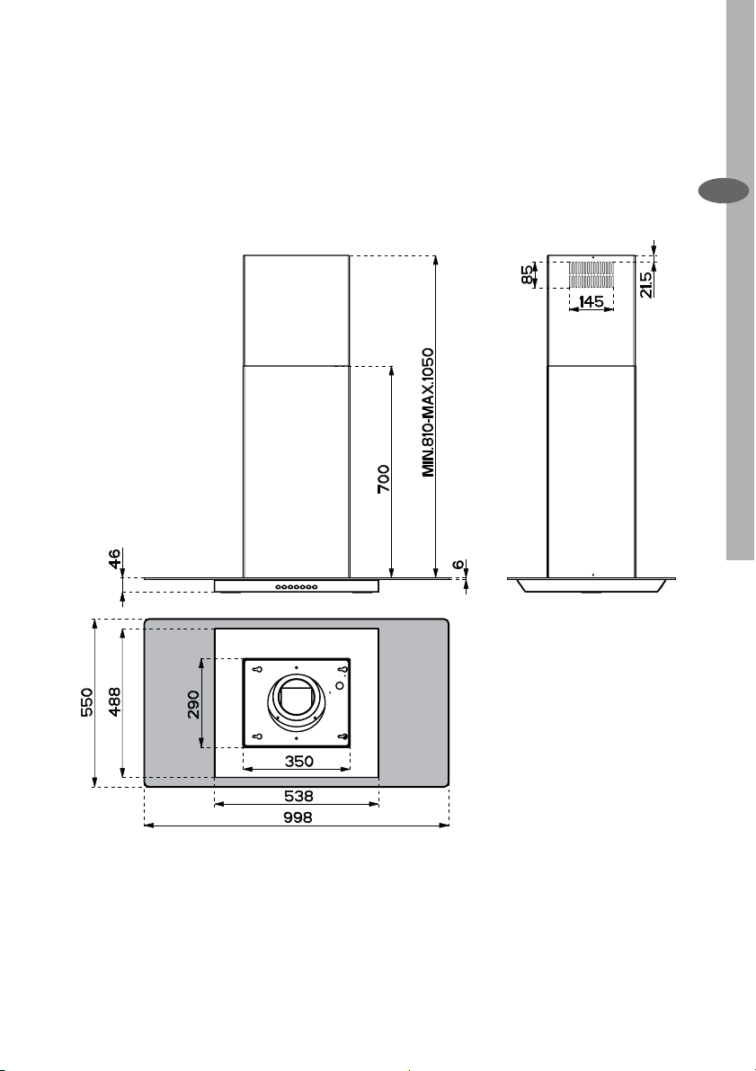
CHARACTERISTICS
Dimensions
Characteristics electrolux 7
EN
Page 8
8 electrolux Characteristics
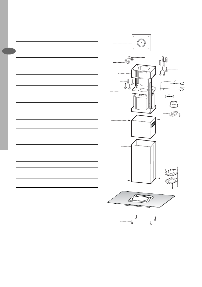
Components
Ref. Q.ty Product Components
1 1 Hood Body, complete with: Con-
EN
2 1 Telescopic Chimney comprising:
2.1 1 Upper Section
2.2 1 Lower Section
7.1 1 Telescopic frame complete with
7.1a 1 Upper frame
7.1b 1 Lower frame
9 1 Reducer Flange ø 150-120 mm
10 1 Flange ø 150
15 1 Air Outlet Connection
24 1 Junction box
25 2 Pipe clamps
Ref. Q.ty Installation Components
11 4 Wall Plugs ø 10
12c 6 Screws 2,9 x 6,5
12e 2 Screws 2,9 x 9,5
12f 4 Screws M6 x 10
12g 4 Screws M6 x 80
12h 4 Screws 5,2 x 70
21 1 Drilling template
22 4 6.4 mm int. dia washers
23 4 M6 nuts
Q.ty Documentation
1 Instruction Manual
trols, Light, Blower, Filters
extractor, consisting of:
21
23
22
7.1a
12g
7.1
7.1b
12c
2.1
2
2.2
12c
1
9
12c
25
12e
11
12h
15
10
24
12f
Page 9
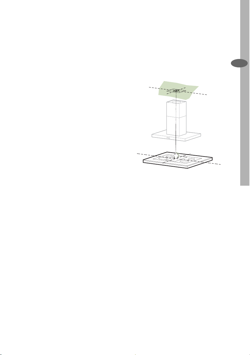
INSTALLATION
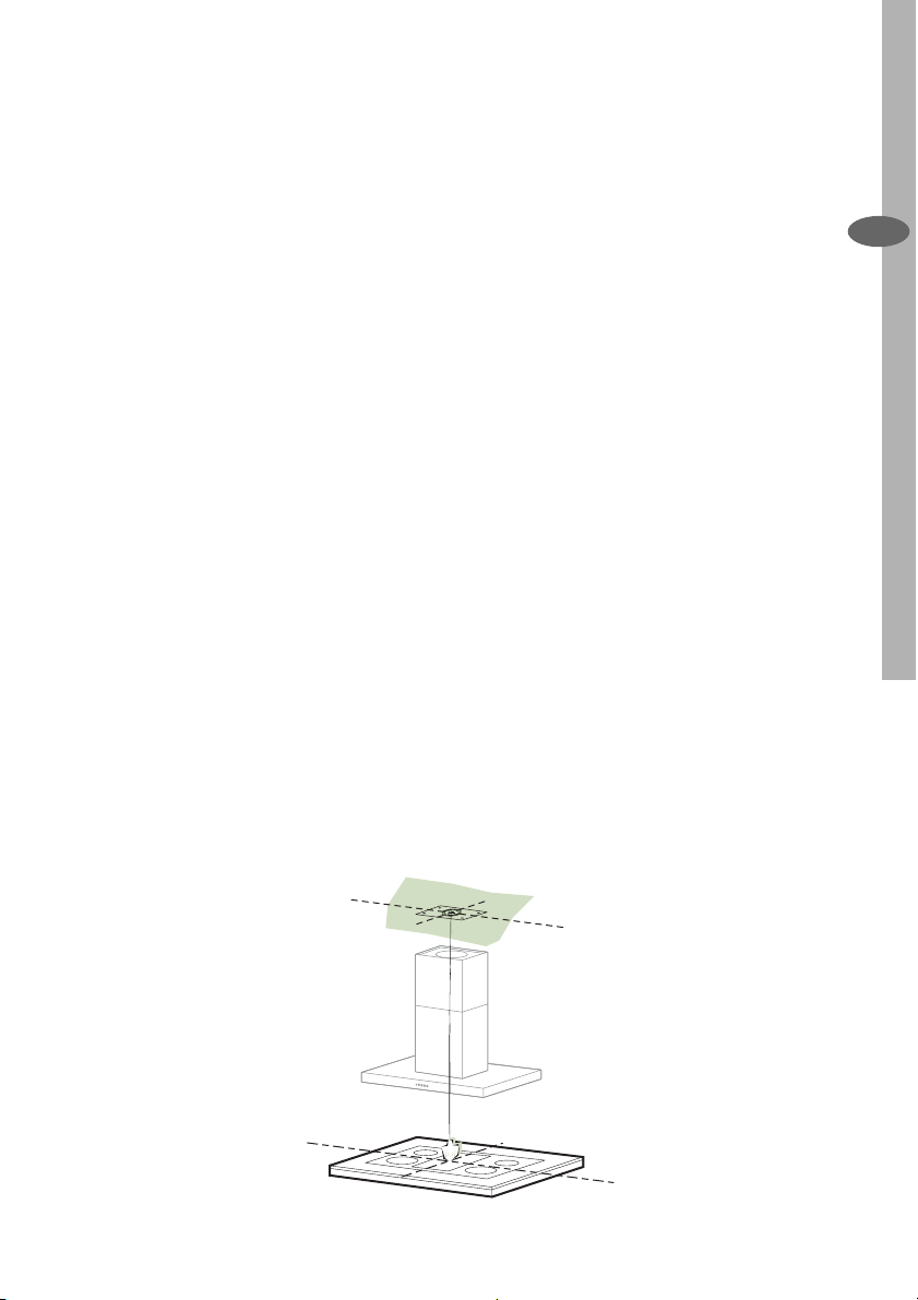
Drilling the Ceiling/shelf
• Use a plumb line to mark the centre of
the hob on the ceiling/support shelf.
• Place the drilling template 21 provided
on the ceiling/support shelf, making
sure that the template is in the correct
position by lining up the axes of the
template with those of the hob.
• Mark the centres of the holes in the
template.
• Drill the holes at the points marked:
• for concrete ceilings, drill for plugs
appropriate to the screw size.
• for hollow brick ceilings with wall
thickness of 20 mm: drill ø 10
mm(immediately insert the Dowels
11 supplied).
• for wooden beam ceilings, drill ac-
cording to the wood screws used.
• for wooden shelf, drill ø 7 mm.
• for the power supply cable feed, drill
ø 10 mm.
• for the air outlet (Ducted Version),
drill according to the diameter of the
external air exhaust duct connection.
• Insert two screws of the following
type, crossing them and leaving 4-5
mm from the ceiling:
• for concrete ceilings, use the appro-
priate plugs for the screw size (not
provided).
• for Cavity ceiling with inner space,
with wall thickness of approx. 20
mm, Screws 12h, supplied.
• for wooden beam ceilings, use 4
wood screws (not provided).
• for wooden shelf, use 4 screws 12g
with washers 22 and nuts 23, provided.
Installation electrolux 9
EN
Page 10
10 electrolux Installation
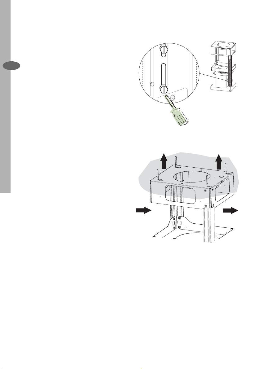
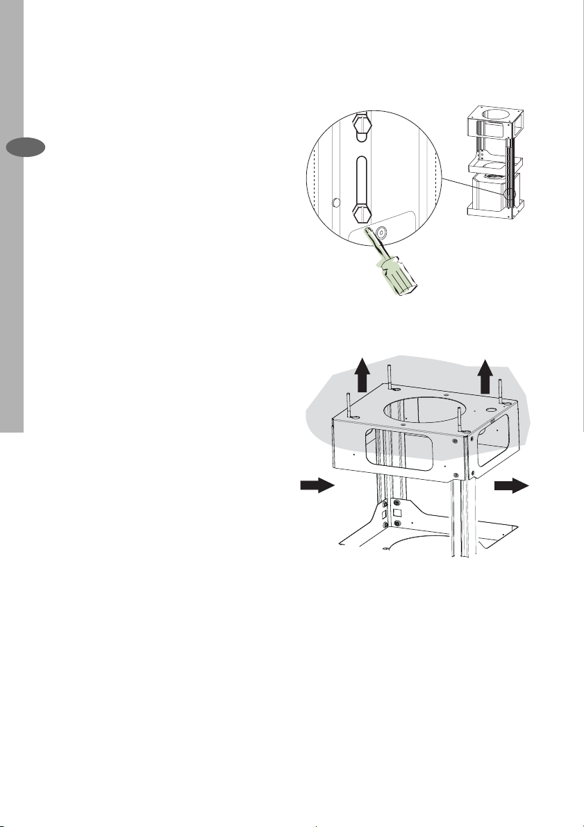
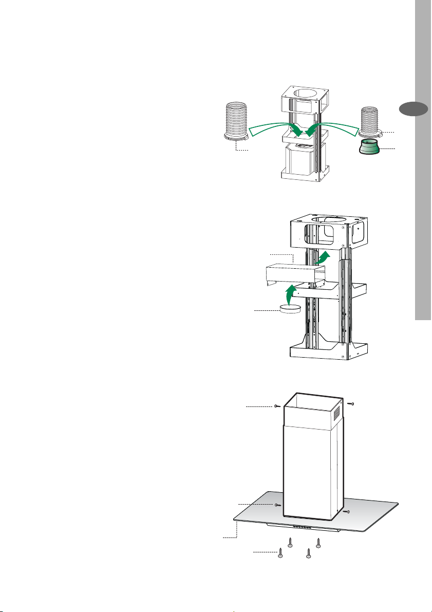
Fixing the frame
• Loosen the two screws fastening the
lower chimney and remove this from
EN
the lower frame.
• Loosen the two screws fastening the
upper chimney and remove this from
the upper frame.
If you wish to adjust the height of the
frame, proceed as follows:
• Unfasten the eight metric screws joining the two columns, located at the
sides of the frame.
• Adjust the frame to the height required, then replace all the screws
removed as above.
• Insert the upper chimney stack from
above, and leave it running free on the
frame.
• Lift up the frame, fi t the frame slots
onto the screws up to the slot end
positions.
• Tighten the two screws and fasten
the other two screws provided with
the hood.
Before tightening the screws completely
it is possible to adjust the frame by turning it. Make sure that the screws do
not come out of their seats in the slotted
holes.
• The frame mountings must be secure
to withstand the weight of the hood
and any stresses caused by the occasional side thrust applied to the
device.
On completion, check that the base is
stable, even if the frame is subjected
to bending.
• In all cases where the ceiling is not
strong enough at the suspension
point, the installer must provide
strengthening using suitable plates
and backing pieces anchored to the
structurally sound parts.
1
2
1
2
Page 11
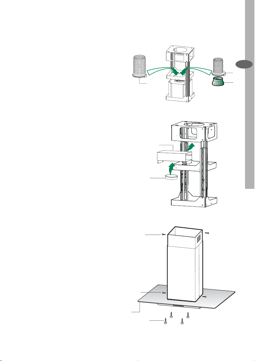
Connection in Ducting Version
When installing the ducting version,
connect the hood to the chimney using
either a fl exible or rigid pipe ø 150 or
120 mm, the choice of which is left to
the installer.
• To install a ø 120 mm air exhaust connection, insert the reducer fl ange 9 on
the hood body outlet.
• Fix the pipe using the pipe clamps 25
provided.
• Remove charcoal fi lters, if present.
Connection in Recycling Version
• Fix the connection 15 to the frame
using the 4 screws provided.
• Fix the fl ange 10 to the lower opening
of the connection 15.
• Connect the hood air outlet to the
fl ange in the lower part of the junction
using a rigid or fl exible ø 150 tube (by
installer’s choice).
• Ensure that the charcoal fi lters have
been fi tted.
ø 150
Installation electrolux 11
ø 120
EN
25
25
15
10
9
Chimney assembly / Mounting
the hood body
• Position the upper chimney section
and fi x the upper part to the frame
using the 2 screws 12c (2,9 x 6,5)
provided.
• Similarly, position the lower chimney
section and fi x the lower part to the
frame using the 2 screws 12c (2,9 x
6,5) provided.
Before fi xing the hood body to the fra-
me:
• Remove the grease fi lters from the
hood body.
• Remove charcoal fi lters, if present.
• From below, use the 4 screws 12f
(M6 x 10)provided to fi x the hood
body to the frame.
12c
12c
1
12f
Page 12
12 electrolux Installation / Use
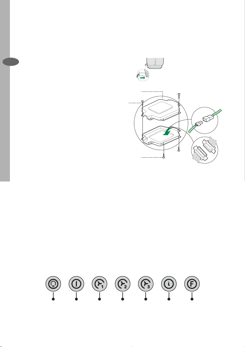
Electrical Connection
• Connect the hood to the mains
EN
through a two-pole switch having a
contact gap of at least 3 mm.
• Remove the grease fi lters (see para-
graph Maintenance) being sure that
the connector of the feeding cable is
correctly inserted in the socket placed
on the side of the fan.
• Connect the control connector Cmd.
• Connect the lights connector Lux.
• Place the connectors in the junction
box 24 and close it using the 2 screws
12e (2,9 x 9,5) provided.
• Fix the junction box to the hood body
using the 2 screws 12c (2,9 x 6,5)
provided.
• For the recirculation version, fi t the
activated carbon odour fi lter.
• Replace the grease fi lters.
12e
24
12c
Lux
Cmd
USE
The hood can be switched on pushing
directly onto the requested speed
without fi rstly having to select 0/1 but-
ton
L T1 T2 T3 T4 T5 F
Page 13
Touch
Basic functions Indicator lights
control
Dual Function
When briefl y pressed it switches the lighting
L
system on and off.
When pressed for 2 seconds it starts the
lighting system in “courtesy light” mode.
The lamps are fed at a reduced power of
approximately 5W. Such function can be
stopped by pressing the touch control for 2
seconds or just by pressing it shortly in order to
return to the normal lighting mode. In courtesy
light mode the touch control is not lit.
When pressed the motor is stopped, regardless
T1
of the speed it is set to.
When pressed the motor is set to the fi rst speed
T2
By a brief pressing the motor is set to the second
T3
speed.
By pressing the touch control for approximately
2 seconds the Delay function is enabled, i.e
delayed shutdown of the appliance ensuring
a complete elimination of the residual odours.
This function can be activated at OFF-position
and at 1°, 2° and 3°speeds. It can be stopped
in advance by pressing any of the touch
controls (T) with the exception of T3. The Delay
function works according to the following
scheme:
1°speed / OFF = 20 minuets
2°speed = 15 minutes
3°speed = 5 minutes
When pressed the motor is set to the third speed Touch control lit
T4
When pressed the motor is set to the intensive
T5
speed timed to 5 minutes. At the end of 5
minutes of intensive speed the hood starts again
at the speed it was set to previously. In case the
hood is set to the intensive speed directly from
OFF-state it will then start from the fi rst speed
after 5 minutes of intensive speed.
When pressed for 4 seconds it resets the fi lter
F
alarm signal indicated by fl ashing of the touch
control T1. This procedure can be carried out
only when the motor is stopped.
Touch control
unlit
Touch control lit Lights on
Touch control
unlit
Touch control lit Motor on
Touch control
unlit
Touch control lit Second speed on
Flashing touch
control
Touch control lit Metal grease fi lters saturation
Flashing touch
control
Use electrolux 13
Lights off
EN
Courtesy light on
Motor off
Touch control lit
Delay function on
Touch control lit
alarm. Metal grease fi lters need
to be washed. The alarm starts
up after 100 working hours.
Charcoal fi lter saturation
alarm. Charcoal fi lter has to
be replaced and metal grease
fi lters washed. The alarm
starts up after 200 working
hours. (Activation; check the
paragraph “Charcoal fi lter”)
Page 14
14 electrolux Maintenance
MAINTENANCE
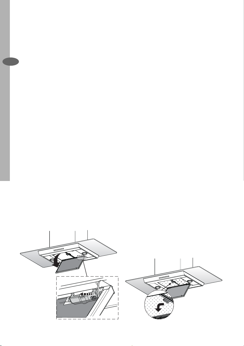
Cleaning the Comfort Panels
• Pull the Comfort Panel to open it.
• Disconnect the panel from the hood
EN
canopy by sliding the fi xing pin lever.
• The comfort panel must never be
washed in a dishwasher.
• Clean the outside using a damp cloth
and neutral liquid detergent.
• Clean the inside as well using a damp
cloth and neutral detergent; do not
use wet cloths or sponges, or jets of
water; do not use abrasive substances.
• When the above operation has been
completed, hook the panel back to
the hood canopy and close it by turning the knob in the opposite direction.
Cleaning of the Metal Cassette
Filters
Alarm reset
• Stop the motor.
• Press the F -touch control for at least
4 seconds until the T1 -touch control
fl ashes.
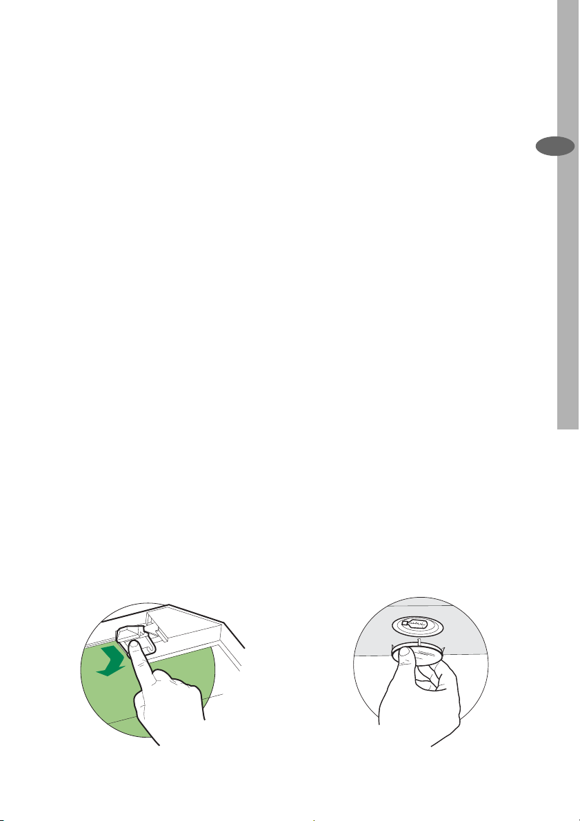
Cleaning the fi lters
• Filters can be washed in the dish machine. They need to be washed every
2 months or even more frequently in
case of particularly intensive use of
the hood.
• Pull the Comfort Panel to open it.
• Remove the fi lters one by one pushing
them lateraly and simultaneously pulling downwards.
• Any kind of bending of the fi lters has
to be avoided when washing them.
Before fi tting them again into the hood
make sure that they are completely
dry (The colour of the fi lter surface
may change throughout the time but
this has no infl uence to the fi lter ef-
fi ciency).
• When fi tting the fi lters into the hood
pay attention that they are placed in
correct position and that the handle
faces outwards.
• Close the comfort panel.
Page 15
Maintenance electrolux 15
Replacing the Charcoal Filter
This fi lter cannot be washed or regene-
rated, and must be replaced when the F
touch control starts to fl ash, or at least
once every 4 months. The alarm is only
triggered when the motor is on.
Enabling/Disabling the alarm signal
• In Recirculation Version Hoods, the
Filter saturation Alarm must be enabled at the time of installation or later.
• Switch off the lights and the motor.
• Disconnect the mains power supply
to the hood by removing the motor
unit power supply cable connector,
switching off the power supply at the
Mains or turning the Main switch off.
• Restore the connection, pressing and
holding T2.
• Release the touch control, touch
controls L, T2 and F will light up normally.
• Within 3 seconds press the touch
control F until the key itself fl ashes to
confi rm as follows:
• 2 fl ashes – Charcoal Filter saturation
Alarm ENABLED
• 1 fl ash - Charcoal Filter saturation
Alarm DISABLED
Reset the alarm signal
• Stop the motor.
• Press the touch control F for at least
4 seconds, until the touch control T1
fl ashes.
Replace the Filter
• Pull the Comfort Panel to open it.
• Remove the metal grease fi lters.
• Remove the saturated charcoal fi lter,
turning the fasteners provided.
• Fit the new fi lter and fasten it its cor-
rect position.
• Put the metal grease fi lters in their
seats.
• Close the comfort panel.
Light replacement
20 W halogen light.
• Remove the snap-on lamp cover by
levering it from under the metal ring,
supporting it with one hand.
• Remove the halogen lamp from the
lamp holder by pulling gently.
• Replace the lamp with a new one of
the same type, making sure that you
insert the two pins properly into the
housings on the lamp holder.
• Replace the snap-on lamp cover.
EN
Page 16
16 electrolux Empfehlungen und Hinweise
EMPFEHLUNGEN UND HINWEISE
MONTAGE
• Das Gerät darf nur vom Fachpersonal
DE
angeschlossen werden.
• Der Hersteller haftet nicht für Schäden, die
auf eine fehlerhafte und unsachgemäße
Montage zurückzuführen sind.
• Der minimale Sicherheitsabstand zwischen Kochmulde und Haube muss 650
mm betragen.
• Prüfen, ob die Netzspannung mit dem
Wert auf dem im Haubeninneren angebrachten Schild übereinstimmt.
• Bei Geräten der Klasse I ist sicherzustellen, dass die elektrische Anlage des
Wohnhauses über eine vorschriftsmäßige
Erdung verfügt.
• Das Anschlussrohr der Haube zur Luftaustrittsöffnung sollte möglicherweise einen
Durchmesser von 150 mm aufweisen.
Der Rohrverlauf muss so kurz wie möglich
sein.
• Die Haube darf an keine Entlüftungsschächte angeschlossen werden, in die
Verbrennungsgase (Heizkessel, Kamine
usw.) geleitet werden.
• Werden im Raum außer der Dunstabzugshaube andere, nicht elektrisch betriebene
(z.B. gasbetriebene) Geräte verwendet,
muss für eine ausreichende Belüftung
gesorgt werden. Sollte die Küche diesbezüglich nicht entsprechen, ist an einer
Aussenwand eine Öffnung anzubringen,
die Frischluftzufuhr gewährleistet.
BEDIENUNG
• Die Dunstabzugshaube ist ausschließlich
zum Einsatz im privaten Haushalt und zur
Beseitigung von Küchengerüchen vorgesehen.
• Bei unsachgemäßer Benutzung wird keine
Haftung übernommen.
Achtung! Große Flammen bei einge-
schalteter Haube niemals unbedeckt
lassen.
• Die Intensivität der Flamme ist so zu regulieren, dass sie den Topfboden nicht
überragt.
Achtung! Frittiergeräte müssen während des Gebrauchs stets beaufsichtigt werden: Überhitztes Öl kann sich
entzünden.
• Keine fl ambierten Speisen unter der Ab-
zugshaube zubereiten: Brandgefahr.
• Die Dunstabzugshaube darf von Kindern
oder Personen, die hinsichtlich der Bedienung nicht unterwiesen wurden, keinesfalls verwendet werden.
WARTUNG
• Bevor Wartungsarbeiten durchgeführt
werden, muss die Stromzufuhr zur Haube
unterbrochen werden, indem der Stecker
gezogen oder der Hauptschalter abgeschaltet wird.
• Bei der Filterwartung müssen die vom
Hersteller empfohlenen Zeiträume zum
Austauschen der Filter genauestens eingehalten werden.
• Zur Reinigung der Haubenfl ächen Wir
empfehlen ein feuchtes Tuch und ein mildes Flüssigreinigungsmittel.
• Bitte keine Reinigungsmittel mit Scheuermittel verwenden. Die Oberfl äche wird
damit verkratzt.
Das Symbol
seiner Verpackung weist darauf hin,
dass dieses Produkt nicht als normaler
Haushaltsabfall zu behandeln ist, sondern
an einem Sammelpunkt für das Recycling
von elektrischen und elektronischen Geräten
abgegeben werden muss. Durch Ihren
Beitrag zum korrekten Entsorgen dieses
Produkts schützen Sie die Umwelt und die
Gesundheit Ihrer Mitmenschen. Umwelt
und Gesundheit werden durch falsches
Entsorgen gefährdet. Weitere Informationen
über das Recycling dieses Produkts erhalten
Sie von Ihrem Rathaus, Ihrer Müllabfuhr oder
dem Geschäft, in dem Sie das Produkt
gekauft haben.
auf dem Produkt oder
Page 17
CHARAKTERISTIKEN
Platzbedarf
Charakteristiken electrolux 17
DE
Page 18

18 electrolux Charakteristiken
Komponenten
Pos. St. Produktkomponenten
1 1 Haubenkörper mit Schaltern,
DE
2 1 Teleskopkamin bestehend aus:
2.1 1 oberer Kaminteil
2.2 1 unterer Kaminteil
7.1 1 Teleskopgerüst komplett mit Ge-
bläse, bestehend aus:
7.1a 1 oberer Gerüstteil
7.1b 1 unterer Gerüstteil
9 1 Reduzierfl ansch ø 150-120 mm
10 1 Flansch ø 150
15 1 Luftaustritt-Anschlussstück
24 1 Verbindungsdose
25 2 Rohrschellen
Pos. St. Montagekomponenten
11 4 Dübel ø 10
12c 6 Schrauben 2,9 x 6,5
12e 2 Schrauben 2,9 x 9,5
12f 4 Schrauben M6 x 10
12g 4 Schrauben M6 x 80
12h 4 Schrauben 5,2 x 70
21 1 Bohrschablone
22 4 Unterlegscheiben ø 6,4
23 4 Schraubenmuttern M6
St. Dokumentation
1 Bedienungsanleitung
21
23
22
7.1a
12g
7.1
7.1b
12c
2.1
2
2.2
12c
1
9
12c
25
12e
11
12h
15
10
24
12f
Page 19
MONTAGE
Montage electrolux 19
Achtung: Bitte beachten Sie bei der
Montage das Gewicht der kompletten Haube. Die Tragfähigkeit der
Decke oder alternativ der Trägerplatte für diese Zugbelastung muss
vor der Montage geprüft und gegebenenfalls durch die Anbringung
von geeigneten Befestigungs- oder
Stabilisierungselementen hergestellt werden. Kann eine hinreichende Tragfähigkeit nicht sichergestellt
werden, ist von einer Montage
abzusehen.
Bohren der Decke/Tragerplatte
• Mit Hilfe eines Lots den KochmuldenMittelpunkt an der Decke oder Trägerplatte ermitteln und kennzeichnen.
• Die mitgelieferte Bohrschablone 21
so auf die Decke/Trägerplatte legen,
dass die Schablonenmitte mit dem
gekennzeichneten Mittelpunkt übereinstimmt und die Schablonenseiten
auf die Seiten der Kochmulde ausrichten.
• Die Mitte der Schablonenbohrungen
kennzeichnen.
• Die gekennzeichneten Punkte bohren:
• Massivbeton-Decke: je nach verwendeten Beton-Dübeln.
• Decke aus Hohlkammer-Ziegeln mit
20 mm Wandungsstärke: ø 10 mm
(sofort die mitgelieferten Dübel 11
einfügen).
• Holzbalkendecke: je nach verwendeten Holzschrauben.
• Holz-Trägerplatte: ø 7 mm.
• Durchgang für das Speisekabel: ø
10 mm.
• Luftaustritt (Abluftversion): je nach
Durchmesser des Anschlussrohres
für die Luftableitung.
• Zwei sich gegenüberliegende Schrauben festziehen und 4-5 mm Freiraum
zur Decke belassen:
• bei Massiv-Betondecken mit spezi-
ellen Betondübeln, die nicht mitgeliefert werden;
• für Hohlkammer-Ziegeln mit ca. 20
mm Wandungsstärke die mitgelieferten Schrauben 12h verwenden;
• bei Holzbalken-Decken mit 4 Holz-
schrauben, die nicht mitgeliefert
werden;
• bei Holz-Trägerplatten mit 4 Schrau-
ben 12g, Unterlegscheiben 22 und
Schraubenmuttern 23, die im Lieferumfang enthalten sind.
DE
Page 20
20 electrolux Montage
Montage des Teleskopgerüsts
• Die beiden Schrauben lösen, die den
unteren Gerüstteil fi xieren und diesen
DE
aus dem Gerüst ziehen (an der Unterseite)
• Die beiden Schrauben lösen, die den
oberen Gerüstteil fi xieren und diesen
aus dem Gerüst ziehen (an der Oberseite).
Für eine eventuelle Regulierung der Gerüsthöhe folgendermaßen vorgehen:
• Die acht Stellschrauben an den
Gerüstseiten, die die beiden Säulen
vereinen, lösen.
• Den oberen Gerüstteil von oben einfügen und frei auf dem Gerüst lassen.
• Das Gerüst heben, die Langlöcher bei
den Schrauben einrasten und bis zum
Anschlag laufen lassen;
• Die beiden Schrauben festziehen und
die beiden anderen mitgelieferten
Schrauben einschrauben;
Bevor die Schrauben defi nitiv festgezo-
gen werden, kann eine Regelung durch
Bewegen des Gerüstes erfolgen, wobei
darauf zu achten ist, dass die Schrauben nicht aus dem Sitz des Regellangloches austreten.
• Wir verweisen auf die Notwendigkeit
einer absolut sicheren Befestigung
des Teleskopgerüsts, die sowohl dem
Eigengewicht der Haube wie auch
dem seitlichen Druck, der auf das
Gerät einwirken kann, entsprechen
muss. Nach erfolgter Montage ist zu
prüfen, ob das Teleskopgerüst auch
bei Biegebeanspruchung stabil ist.
• Sollte die Decke am Befestigungspunkt nicht robust genug sein, muss
der Installateur geeignete Platten
und Gegenplatten verwenden, die an
strukturell widerstandsfähigen Teilen
verankert werden.
1
2
1
2
Page 21
Anschluss in Abluftversion
Bei Abluftbetrieb kann die Haube vom
Installateur wahlweise mittels Rohr oder
Schlauch (ø 150 oder 120 mm) an die
Außenrohrleitung angeschlossen werden.
• Bei Verwendung eines Anschlussrohres ø 120 den Reduzierfl ansch 9 am
Haubenaustritt anbringen.
• Das Rohr mit den mitgelieferten Rohrschellen 25 fi xieren.
• Eventuell vorhandene Aktivkohlefi lter
entnehmen.
Anschluss in Umluftversion
• Der Anschluß 15 an das Teleskopgerüst mit den 4 beiliegenden Schrauben befestigen.
• Den Flansch 10 an die untere Bohrung des Anschluß 15 anbringen.
• Den Haubenluftaustritt mit Hilfe eines
Rohres oder Schlauches Ø 150 (die
Wahl bleibt dem Installateur überlassen) mit dem Flansch, der sich unter
dem Umlenkteil befi ndet, verbinden.
ø 150
Montage/Bedienung electrolux 21
25
15
10
ø 120
DE
25
9
Kaminmontage und Montage
des Haubenkörpers
• Den oberen Kaminteil positionieren
und beim oberen Gerüstteil mit Hilfe
der 2 mitgelieferten Schrauben 12c
(2,9 x 6,5) fi xieren.
• Gleichermaßen den unteren Kaminteil
positionieren und beim unteren Gerüstteil mit Hilfe der 2 mitgelieferten
Schrauben 12c (2,9 x 6,5) fi xieren.
Vor der Montage des Haubenkörpers
am Teleskopgerüst:
• Die Fettfi lter entnehmen.
• Eventuell vorhandene Aktivkohle-Geruchsfi lter entnehmen.
• Dann den Haubenkörper mit Hilfe der
4 mitgelieferten Schrauben 12f (M6 x
10) von unten her am Teleskopgerüst
fi xieren.
12c
12c
1
12f
Page 22

22 electrolux Bedienung
Elektroanschluss
• Bei Anschluss der Haube an das
Stromnetz muss ein zweipoliger
DE
Schalter mit einem Öffnungsweg von
mindestens 3 mm zwischengeschaltet werden.
• Entfernen Sie die Fettfi lter (s. Ab-
schnitt „Wartung“) und versichern Sie
sich, daß die Kabelverbindung in die
Steckdose des Gebläses einwandfrei
eingesteckt wird.
• Den Verbinder der Steuerungen Cmd
anschlie- ßen.
• Den Verbinder der Beleuchtung Lux
anschließen.
• Den Verbinder wieder in die Verbindungsdose 24 stecken und diese mit
den 2 mitgelieferten Schrau-ben 12e
(2,9 x 9,5) verschließen.
• Die Verbindungsdose mit den 2 beiliegenden Schrauben 12c (2,9 x 6,5) am
Haubenkörper fi xieren.
• Bei Umluftbetrieb den Aktivkohle-Geruchsfi lter montieren.
• Die Fettfi lter wieder montieren.
12e
24
12c
Lux
Cmd
BEDIENUNG
Die Haube kann direkt auf die gewünschte Stufe eingeschaltet werden
ohne daß man vorher auf die Gebläsetaste 0/1 drückt.
L T1 T2 T3 T4 T5 F
Page 23

Taste Grundfunktion Leuchtsignale
Doppelfunktion
Ein kurzer Tastendruck schaltet die Beleuchtungsanlage ein
L
und aus.
Wird die Taste 2 Sekunden lang gedrückt, schaltet sich die
Elektrolumineszenz-Beleuchtung ein und aus. Diese
Funktion ist von der Grundfunktion unabhängig, d.h. die
Beleuchtung und die Elektrolumineszenz können gleichzeitig
eingeschaltet werden. Im Modus „ElektrolumineszensBeleuchtung” leuchtet die Taste nicht auf
Schaltet den Motor unabhängig von der Gebläsestufe ab Taste leuchtet
T1
Aktiviert den Motor mit der ersten Gebläsestufe
T2
Bei kurzem Drücken dieser Taste wird der Motor mit der
T3
zweiten Gebläsestufe aktiviert
Wird die Taste cirka 2 Sekunden lang gedrückt, aktiviert
sich die Funktion Delay, d.h. die verzögerte Abschaltung
des Gerätes. Eignet sich zur kompletten Beseitigung
von Restgerüchen. Kann in der Position OFF und den
Gebläsestufen 1, 2, 3 aktiviert werden; kann vorzeitig durch
Drücken jeder beliebigen Taste (T) (mit Ausnahme der Taste
T3) deaktiviert werden. Die Delay-Funktion erfolgt nach
nachstehendem Zeitplan:
1. Stufe / OFF = 20 Minuten
2. Stufe = 15 Minuten
3. Stufe = 5 Minuten
Aktiviert den Motor mit der dritten Gebläsestufe
T4
Aktiviert den Motor mit der 5 Minuten dauernden Intensivstufe.
T5
Nach Ablauf der 5 Minuten läuft das Gerät wieder mit der zuvor
eingestellten Sauggeschwindigkeit. Wird diese Funktion bei
abgeschaltetem Gerät aktiviert, wird nach Ablauf der 5 Minuten
auf die erste Gebläsestufe übergegangen.
Wird die Taste 4 Sekunden lang gedrückt, erfolgt die
F
Rückstellung des Filteralarms, der durch Blinken der Taste T1
angezeigt wird. Dieses Verfahren kann nur bei abgeschaltetem
Motor durchgeführt werden.
Taste
erloschen
Taste
erloschen
Taste leuchtet
auf
Taste
erloschen
auf
Taste
erloschen
Taste leuchtet
auf
Taste blinkt Delay-Funktion aktiviert
Taste leuchtet auf Sättigungsanzeige
Taste blinkt Sättigungsanzeige der
Wartung electrolux 23
Beleuchtung abgeschaltet
Beleuchtung abgeschaltet
Beleuchtung eingeschaltet
Elektrolumineszenz
eingeschaltet
Motor aktiviert
Motor deaktiviert
Taste leuchtet auf
Zweite Gebläsestufe aktiviert
Taste leuchtet auf
Taste leuchtet auf
der Metallfettfi lter, die
gewaschen werden
müssen. Der Alarm erfolgt
nach 100 effektiven
Arbeitsstunden der
Haube.
Aktivkohle-Geruchsfi lter,
falls diese aktiviert
wurde; die Filter
sind auszutauschen;
die Metallfettfi lter
müssen ebenfalls
gewaschen werden. Die
Sättigungsanzeige des
Aktivkohle-Geruchsfi lters
erfolgt nach 200 effektiven
Arbeitsstunden der
Haube. (Aktivierung siehe
Abschn.
Geruchsfi lter)
DE
Page 24

24 electrolux Wartung
WARTUNG
Reinigung der Comfort Panel
• Den Comfort Panel durch Ziehen öffnen.
DE
• Die Platte vom Haubenkörper aushaken, indem der Hebel des Befestigungsstiftes verschoben wird.
• Die Comfort Panel darf keinesfalls im
Geschirrspüler gewaschen werden.
• Außen mit einem feuchten Lappen
und neutralem Flüssigreiniger säubern.
• Innen mit einem feuchten Lappen und
neutralem Reinigungsmittel säubern;
keine nassen Lappen oder Schwämme oder Wasserstrahl verwenden;
kein Scheuermittel verwenden.
• Am Ende die Platte wieder am Haubenkörper einhaken und schließen,
indem der Drehknopf in die dem
Öffnen entgegengesetzte Richtung
gedreht wird.
Selbsttragender Metallfettfi lter
reinigung
Rückstellen der Sättigungsanzeige
• Den Gebläsemotor abschalten.
• Die Taste F mindestens 4 Sekunden
lang drücken, bis die Taste T1 als Bestätigung zu blinken beginnt.
Filterreinigung
• Die Filter können auch im Geschirrspüler gereinigt werden und sollten
cirka alle 2 Monate - bzw. bei sehr
intensivem Einsatz auch häufi ger -
gereinigt werden.
• Den Comfort Panel durch Ziehen öffnen.
• Die Filter einzeln entnehmen, indem
sie zur Rückseite der Gruppe geschoben und gleichzeitig nach unten
gezogen werden.
• Die Filter waschen, darauf achten, sie
nicht zu verbiegen und vor der Remontage trocknen lassen.
• Bei der Remontage darauf achten,
dass sich der Griff an der sichtbaren
Außenseite befi ndet.
• Die Comfort Panel wieder schließen.
Page 25

Wartung electrolux 25
Austauschen der Aktivkohle Filter
Dieser Filter ist weder wasch- noch wiederverwendbar und ist auszutauschen,
wenn die Taste F blinkt oder zumindest
alle 4 Monate. Die Sättigungsanzeige
erfolgt nur, wenn der Gebläsemotor
eingeschaltet ist.
Aktivierung/Deaktivierungder Sätti-
gungsanzeige
• Bei Hauben mit Umluftbetrieb erfolgt
die Aktivierung der Sättigungsanzeige
bei der Installation oder später.
• Die Beleuchtung und den Gebläsemotor abschalten.
• Die Haube vom Stromnetz trennen,
indem der Verbinder des Speisekabels der Motorgruppe gezogen oder
der zwischengeschaltete zweipolige
Schalter oder der Hauptschalter betätigt wird.
• Den Anschluss wieder herstellen,
während die Taste T2 gedrückt gehalten wird.
• Die Taste loslassen; die Tasten L, T2
und F leuchten pausenlos auf.
• Innerhalb von 3 Sekunden die
Taste F solange drücken, bis sie als
Bestätigung zu blinken beginnen:
• 2-maliges Blinken – Sättigungsan-
zeige Aktivkohle-Geruchsfi lter AK-
TIVIERT
• 1-maliges Blinken – Sättigungs-
anzeige Aktivkohle-Geruchsfi lter
DEAKTIVIERT
Rückstellen der Sättigungsanzeige
• Den Gebläsemotor abschalten.
• Die Taste F mindestens 4 Sekunden
lang drücken, bis die Taste T1 als Bestätigung zu blinken beginnt
Filterwechsel
• Den Confort Panel durch Ziehen öffnen.
• Die Metallfettfi lter entfernen.
• Den gesättigten Aktivkohle-Geruchsfi lter anhand der entsprechenden
Anhakvorrichtungen demontieren.
• Den neuen Filter montieren, indem er
in seinem Sitz eingehakt wird.
• Die Metallfettfi lter wieder montieren.
• Die Confort Panel wieder schließen.
AUSWECHSELN DER LAMPEN
Halogenlampe 20 W
• Vor dem Auswechseln der Lampen,
die mittels Eindrücken befestigte
Glashalterung aus Metall durch Anheben der Zwinge entfernen und die
Halterung dabei mit einer Hand stützen.
• Die Lampe aus der Halterung nehmen.
• Die Lampe durch eine gleichwertige
ersetzen und bei der Remontage
darauf achten, daß die beiden Steckerstifte vorschriftsmäßig in die Lampenfassung eingeführt werden.
• Die Glashalterung wieder eindrücken.
DE
Page 26

26 electrolux Consejos y Sugerencias
CONSEJOS Y SUGERENCIAS
Installación
• El fabricante declina cualquier responsabilidad debida a los daños provoca-
ES
dos por una instalación incorrecta o
no conforme con las reglas.
• La distancia mínima de seguridad entre la encimera y la campana debe ser
de 650 mm.
• Comprobar que la tensión de red
corresponda a la indicada en la placa
situada en el interior de la campana.
• Para los aparatos de 1ª clase asegurarse de que la instalación eléctrica
doméstica posea una toma de tierra
efi caz.
• Conectar la campana a la salida del
aire de aspiración mediante un tubo
de 120mm de diámetro como mínimo. El recorrido del tubo debe ser lo
más corto posible.
• No conectar la campana a tubos de
descarga de humos producidos por
combustión (calderas, chimeneas,
etc.).
• En el caso que en la cocina se utilice
de manera silmultánea la campana
y otros aparatos no eléctricos (por
ejemplo aparatos de gas), debe existir
un sistema de ventilación sufi ciente
para todo el ambiente. Si la cocina
no posee un orifi cio que comunique
con el exterior, hay que realizarlo para
garantizar el recambio del aire.
Uso
• La campana ha sido concebida exclusivamente para un uso doméstico,
para eliminar los olores de la cocina.
No utilizarla de manera inadecuada.
• No dejar llamas libres de fuerte intensidad mientras la campana esté
funcionando.
• Regular siempre las llamas de manera
que éstas no sobresalgan lateralmente con respecto al fondo de las ollas.
• Controlar las freídoras durante su uso:
el aceite muy caliente se puede infl a-
mar.
• No preparar alimentos fl ambè debajo
de la campana de la cocina; peligro
de incendio
• La campana no debe ser utilizada por
niños o personas que no conozcan su
uso correcto.
Mantenimiento
• Antes de efectuar cualquier operación
de mantenimiento, desenchufar la
campana de la red eléctrica o apagar
el interruptor general.
• Efectuar un mantenimiento escrupuloso e inmediato de los fi ltros, según
los intervalos de tiempo aconsejados.
• Para limpiar las superfi cies de la cam-
pana es sufi ciente utilizar un trapo
mojado y detergente líquido neutro.
El símbolo en el producto o en su
embalaje indica que este producto no se
puede tratar como desperdicios normales
del hogar. Este producto se debe entregar al
punto de recolección de equipos eléctricos
y electrónicos para reciclaje. Al asegurarse
de que este producto se deseche
correctamente, usted ayudará a evitar
posibles consecuencias negativas para el
ambiente y la salud pública, lo cual podría
ocurrir si este producto no se manipula de
forma adecuada. Para obtener información
más detallada sobre el reciclaje de este
producto, póngase en contacto con la
administración de su ciudad, con su servicio
de desechos del hogar o con la tienda
donde compró el producto.
Page 27

CARACTERÍSTICAS
Dimensiones
Características electrolux 27
ES
Page 28

28 electrolux Características
Componentes
Ref. Cant. Componentes de Producto
ES
1 1 Cuerpo Campana dotado de :
Mandos, Luz, Filtros
2 1 Chimenea telescópica formada
por:
2.1 1 Chimenea superior
2.2 1 Chimenea inferior
7.1 1 Torreta telescópica dotada de
Aspirador, formada por:
7.1a 1 Torreta superior
1 Torreta inferior
9 1 Brida de reducción ø 150-120
mm
10 1 Brida ø 150
15 1 Racor Salida de Aire
24 1 Caja de conexiones
25 2 Abrazaderas ajustables
26 2 Pasacable
27 1 Tapón de acabado
Ref. Cant. Componentes de Instalación
11 4 Tacos ø 10
12c 6 Tornillos 2,9 x 6,5
12e 3 Tornillos 2,9 x 9,5
12f 4 Tornillos M6 x 10
12g 4 Tornillos M6 x 80
12h 4 Tornillos 5,2 x 70
21 1 Patrón de perforación
22 4 Arandelas øi 6,4
23 4 Tuercas M6
Cant. Documentación
1 Manual de instrucciones
21
23
22
7.1a
12g
7.1
7.1b
12c
2.1
2
2.2
12c
1
12f
9
12c
25
12e
11
12h
15
10
24
Page 29

INSTALACIÓN
Taladrado cielorraso/repisa
• Con la ayuda de un hilo de plomo
marcar en el cielorraso/repisa de soporte el centro del plano de cocción.
• Apoyar en el cielorraso/repisa la plantilla de taladrado 21 en dotación, haciendo coincidir su centro con el centro proyectado y alineando los ejes de
la plantilla con los ejes del plano de
cocción .
• Marcar los centros de los orifi cios de
la plantilla.
• Taladrar los puntos marcados:
• Cielo de hormigón macizo: según
los tacos para hormigón empleados.
• Cielo de ladrillos huecos, con espe-
sor resistente de 20 mm: ø 10 mm
(inserir rápidamente los Tacos 11 en
dotación).
• Cielo con vigas de madera: según
los tornillos para madera empleados.
• Repisa de madera: ø 7 mm.
• Paso del cable eléctrico de aliment-
ación: ø 10 mm.
• Salida aire (Versión Aspirante):
según el diámetro de la conexión a
la tubería de evacuación externa.
• Atornillar, cruzándolas y dejando 4-5
mms del techo, dos tornillos:
• Para hormigón macizo, tacos para
hormigón, no en dotación.
• Para Ladrillo con cámaras de aire,
con espesor resistente de unos 20
mms , Tornillos 12h, en dotación.
• Para vigas de madera, 4 tornillos
para madera, no en dotación.
• Para repisa de madera, 4 tornillos
12g con arandelas 22 y tuercas 23,
en dotación.
Instalación electrolux 29
ES
Page 30

30 electrolux Instalación
Fijación del armazón
• Desenroscar los dos tornillos que sujetan la chimenea inferior y sacarla del
armazón (por la parte inferior)
• Desenroscar los dos tornillos que
ES
sujetan la chimenea superior y sacarla
del armazón (por la parte superior)
En el caso en que se desee regular la
altura del armazón, proceder de la siguiente manera:
• Destornillar los ocho tornillos mé-
tricos que unen las dos columnas,
situados a los lados del armazón.
• Regular a la altura deseada al arma-
zón y volver a atornillar los tornillos
que se han quitado previamente.
• Colocar la chimemea superior des-
de arriba y dejarla libre en el armazón.
• Levantar el armazón, encajar los
ojales en los tornillos y deslizarlos
hasta el fondo;
• Apretar los dos tornillos y atornillar
los otros dos de la dotación;
Antes de apretar defi nitivamente los tor-
nillos pueden realizae regulaciones moviendo el armazón, prestando atención
a que los tornillos no sobresalgan de la
sede del ojal de regulación.
• La fi jación del armazón debe ser se-
gura, hay que considerar el peso de
la campana y el esfuerzo causado por
eventuales empujes laterales al aparato montado. Una vez terminada la
fi jación verifi car que la base sea esta-
ble aunque el armazón sea sometido
a fl exión.
• En todos los casos en que el cielo
raso no es lo sufi cientemente robusto
en el punto de suspensión, el instalador deberá encargarse de reforzarlo
con chapas y contrachapas adecuadas ancladas en partes estructuralmente resistentes.
1
2
1
2
Page 31

Conexiones en la Versión Aspirante
Para la instalación de la versión aspirante, conectar la campana al tubo de
salida mediante un tubo rígido o fl exible
de ø150 o 120 mm, a discreción del
instalador.
• Para la conexión con el tubo de ø120
mm, introducir la brida de reducción 9
en la salida del cuerpo de la campana.
• Fijar el tubo con abrazaderas adecua-
das 25 en dotación.
• Quitar los fi ltros antiolor al carbón ac-
tivo.
Conexiones en la Versión Filtrante
• Sujetar el empalme 15 al armazón
usando los cuatro tornillos incluídos en la
dotación.
• Encajar la arandela 10 en el corres-
pondiente orifi cio inferior del empalme
15.
• Conectar la salida del aire de la cam-
pana con la arandela situada debajo
del empalme mediante un tubo rígido
o fl exible Ø 150 cuya elección se deja
al instalador
ø 150
Instalación electrolux 31
ø 120
ES
25
25
15
10
9
Montaje de la chimenea y fi ja-
ción del cuerpo de la campana
• Colocar la chimenea superior y fi jarla
en la parte superior del armazón con
2 tornillos 12c en dotación.
• De igual manera, colocar la chimenea
inferior y fi jarla en la parte inferior del
armazón con 2 tornillos 12c en dota-
ción.
Antes de fi jar el cuerpo de la campana
al armazón:
• Quitar los fi ltros antigrasa del cuerpo
de la campana.
• Quitar eventuales fi ltros antiolor de
carbón activo.
• Luego fi jar desde abajo, con 4 torni-
llos 12f en dotación, el cuerpo de la
campana al armazón predispuesto
12c
12c
1
12f
Page 32

32 electrolux Instalación/Uso
Conexión eléctrica
• Conectar la campana a la red de
alimentación eléctrica instalando un
interruptor bipolar con apertura de los
contactos de 3 mm como mínimo.
• Quitar los Filtros antigrasa y asegu-
ES
rase de que el conector del Cable
de acometida esté colocado
correctamente en el enchufe del As-
pirador.
• Conectar el conector de los mandos
Cmd.
• Conectar el conector de los focos
Lux.
• Colocar ambos conectores en la caja
de protección 24 cerrándola con los 2
tornillos 12e(2,9 x 9,5) en dotación.
• Fijar la caja de protección en el cuer-
po de la campana con 2 tornillos 12c
(2,9 x 6,5) en dotación.
• Para la versión fi ltrante montar el fi ltro
antiolor de carbón activo.
• Montar nuevamente los fi ltros antigra-
sa.
12e
24
12c
Lux
Cmd
USO
La campana puede encenderse directamente a la velocidad deseada,
presionando la tecla correspondiente
sin pasar por la tecla 0/1 motor.
L T1 T2 T3 T4 T5 F
Page 33

Tecla
Función base Señalizaciones luminosas
Doble Función
Presionada brevemente enciende y apaga la
L
instalación de iluminación.
Al presionar la tecla por 2 segundos se activa
la instalación de iluminación en modalidad
“luz auxiliar” Las lámparas son alimentadas a
una potencia reducida de aproximadamente
5W. Dicha función puede desconectarse
volviendo a presionar la tecla por 2 segundos
o presionándola brevemente para pasar
a la modalidad de iluminación normal. En
la modalidad luz auxiliar la tecla no está
iluminada.
Apaga el motor desde cualquiera velocidad
T1
implementada
Activa el motor a la primera velocidad
T2
Presionada brevemente activa el motor a la
T3
segunda velocidad.
Al presionar por aproximadamente 2” la
tecla, se activa la función Delay es decir el
apagado retrasado del aparato. Adecuada
para completar la eliminación de olores
residuales. Activable desde la posición OFF
y desde las velocidades 1,2,3, se desactiva
anticipadamente presionando cualquier tecla
(T) a excepción de T3. El Delay se produce
según el siguiente esquema.
1° velocidad / OFF = 20 minutos
2° velocidad = 15 minutos
3° velocidad = 5 minutos
Activa el motor a la tercera velocidad Tecla encendida
T4
Activa el motor a la velocidad intensiva temporizada
T5
en 5 minutos. Al fi nal de los 5 minutos el aparato
vuelve a la velocidad implementada precedentemente. En el caso de activación desde aparato apagado
al vencer los 5 minutos el sistema vuelve a la primera
velocidad.
Presionado por 4 segundos restablece la señalización
F
de alarma fi ltros señalándola con el parpadeo de la
tecla T1. Este procedimiento es ejecutable sólo con
el motor apagado.
Tecla apagada Luces apagadas
Tecla iluminada Luces encendidas
Tecla apagada Luz auxiliar encendida
Tecla iluminada
Tecla apagada
Tecla encendida Segunda velocidad activa
Tecla
intermitente
Tecla encendida
Tecla
intermitente
Uso electrolux 33
ES
Motor activo
Motor inactivo
Tecla encendida
Función Delay Activa
Tecla encendida
Señala la alarma de saturación
Filtros Antigrasa Metálicos y la
necesidad de lavarlos. La alarma
entra en función después de
100horas de trabajo efectivo de
la Campana
Señala, cuando está activada, la
alarma de saturación Filtro Antiolor al Carbono Activo que debe ser
sustituido;deben lavarse además
los fi ltros Antigrasa Metálicos. La
alarma de saturación Filtro Antiolor
al Carbono Activo entra en función
después de 200 horas de trabajo
efectivo de la Campana (Activación ver párr. Filtro antiolor)
Page 34

34 electrolux Mantenimiento
MANTENIMIENTO
Limpieza de los Confort Panel
• Abrir el Confort Panel tirando de èl.
• Desenganchar el panel del cuerpo
ES
de la campana deslizando la leva del
perno de sujeción.
• El confort panel no se puede lavar en
el lavavajillas.
• Limpiarlo externamente con un paño
húmedo y detergente líquido neutro.
• Limpiarlo internamente usando un
paño húmedo y detergente neutro;
no usar paños o esponjas mojadas, ni
chorros de agua; no usar substancias
abrasivas.
• Una vez fi nalizada la operación volver
a enganchar el panel al cuerpo de la
campana y cerrarlo girando la mano-
pla en sentido contrario al de apertu-
ra
Limpieza de los fi ltros antigrasa
metalicos autoportantes
Reset de la señal de alarma
• Apagar el motor de aspiración
• Apretar la tecla F durante 4 segundos, hasta que relampaguee la tecla
T1
Limpieza de los fi ltros
• Se pueden lavar en el lavavajillas cada
2 meses ó con mayor frecuencia si se
usa la campana intensamente.
• Abrir los confort panel tirando de
ellos.
• Quitar los fi ltros uno a la vez, apre-
tándolos hacia la parte posterior del
grupo y tirando al mismo tiempo hacia
abajo.
• Lavar los fi ltros sin doblarlos, dejando
que se sequen bien antes de volver
a montarlos (si la superfi cie de los fi l-
tros cambia de color, no infl uye en el
correcto funcionamiento y efi cacia de
los fi ltros).
• Volver a colocarlos prestando atención a que las manillas queden hacia
la parte exterior.
• Volver a cerrar el confort panel.
Page 35

Mantenimiento electrolux 35
Substitución fi ltro al carbón ac-
tivo
No se pueden lavar y no son regenerables, hay que substituirlos cuando la
tecla F relampaguea ó, por lo menos,
cada 4 meses. La señalación de alarma se verifi ca solo cuando el motor de
aspiración funciona.
Activación/Desactivación de la
señal de alarma
• En las campanas en versión fi ltrante,
la señalación de la alarma de saturación de los fi ltros se activa cuando se
instala la campana ó sucesivamente.
• Apagar las luces y el motor de aspiración.
• Desconectar la campana, quitando el
cable de acometida, desenchufándola ó quitando momentaneamente los
plomos.
• Volver a conectar la campana apretando la tecla T2.
• Soltar la tecla, las teclas L, T2 y F se
quedan encendidas.
• En el espacio de 3 segundos apretar la tecla F hasta que relampaguee:
• 2 relampagueos - Alarma saturación
fi ltro antiolor al carbón ACTIVADO
• 1 relampagueo - Alarma saturación
fi ltro antiolor al Carbón DESACTIVADO
Reset del señal de alarma
• Apaga el motor de aspiración.
• Apretar la tecla F durante 4 segundos, hasta que relampaguee la tecla
T1.
Substitución del fi ltro
• Abrir los comfort panel tirando de
ellos.
• Quitar los fi ltros antigrasa metálicos.
• Sacar el fi ltro antiolor al carbón activa-
do saturado desenganchándolo.
• Colocar el fi ltro nuevo enganchándolo
en su sede.
• Volver a colocar los fi ltros metálicos
antigrasa.
• Cerrar el comfort panel
Substitución de las lámparas
Focos halógenos de 20 W.
• Quitar la pieza metálica, a presión,
que sujeta el cristal haciendo leva
bajo el anillo,sujetándolo con una
mano.
• Sacar el foco halógeno del casquillo.
• Substituirlo por uno nuevo de
características idénticas, teniendo
cuidado de colocar correctamente
los dos pernos en la sede del casquillo.
• Volver a colocar la pieza metálica a
presión.
ES
Page 36

36 electrolux Conselhos e Sugestões
CONSELHOS E SUGESTÕES
Instalação
• O fabricante declina toda e qualquer
responsabilidade pelos danos decor-
PT
rentes de uma instalação não correcta ou feita não em conformidade com
as normas da boa técnica.
• A distância mínima de segurança entre a placa de cozedura e o exaustor
deve ser de 650 mm.
• Verifi que se a tensão da rede coincide
com a indicada na placa de características aplicada no interior do exaustor.
• Para os aparelhos de Classe I
fi que-se de que a instalação doméstica garanta uma descarga correcta à
terra.
• Ligue o exaustor à saída do ar aspirado utilizando um tubo de diâmetro
igual ou superior a 120 mm. O percurso do tubo deve ser o mais breve
possível.
• Não ligue o exaustor a tubos de descarga de fumaça produzida porcombustão (caldeiras, lareiras, etc...).
• Caso no mesmo local sejam utilizados
quer o exaustor, quer aparelhos não
accionados pela corrente eléctrica
(por exemplo, aparelhos alimentados
a gás), será preciso providenciar uma
ventilação sufi ciente do aposento. Se
a cozinha não possuir uma abertura
que comunique com o exterior, providencie a sua realização para garantir
a entrada de ar limpo.
Uso
• O exaustor foi projectado para ser utilizado exclusivamente em ambientes
domésticos, sendo a sua fi nalidade
a de reduzir os odores de cozedura.
Não utilize o aparelho de maneira imprópria.
a
, certi-
• As chamas de forte intensidade não
devem fi car descobertas enquanto o
exaustor estiver a funcionar.
• Regule sempre as chamas de maneira que não sobressaiam do fundo das
panelas.
• Mantenha as frigideiras sob controlo
durante o uso: o óleo excessivamente
aquecido pode infl amar-se.
• No prepare alimentos fl amejados sob
o exaustor. Perigo de incêndio!
• O exaustor não deve ser utilizado por
crianças ou por pessoas não devidamente habilitadas à sua utilização
correcta.
Manutenção
• Antes de efectuar qualquer operação
de manutenção, desligue o exaustor
tirando a fi cha da tomada de corrente
ou desligando o interruptor geral.
• Faça uma manutenção atenta e rápida dos fi ltros, respeitando os interva-
los aconselhados.
• Para limpar as superfícies do exaustor, é sufi ciente utilizar um pano húmi-
do e detergente líquido neutro.
O símbolo no produto ou na embalagem indica que este produto não pode ser
tratado como lixo doméstico. Em vez disso,
deve ser entregue ao centro de recolha selectiva para a reciclagem de equipamento
eléctrico e electrónico. Ao garantir uma eliminação adequada deste produto, irá ajudar
a evitar eventuais consequências negativas
para o meio ambiente e para a saúde pública, que, de outra forma, poderiam ser
provocadas por um tratamento incorrecto
do produto. Para obter informações mais
pormenorizadas sobre a reciclagem deste
produto, contacte os serviços municipalizados locais, o centro de recolha selectiva da
sua área de residência ou o estabelecimento
onde adquiriu o produto.
Page 37

CARACTERÍSTICAS
Dimensões
Características electrolux 37
PT
Page 38

38 electrolux Características
Componentes
Ref. Qtd. Componentes do Produto
1 1 Corpo do exaustor equipado
PT
2 1 Chaminé telescópica constituída
2.1 1 Chaminé superior
2.2 1 Chaminé inferior
7.1 1 Armação telescópica com aspira-
7.1a 1 Estrutura superior
7.1b 1 Estrutura inferior
9 1 Flange de redução ø 150-120
10 1 Flange de ø 150
15 1 Conexão de saída de ar
24 1 Caixa de ligações
25 2 Braçadeiras para tubos
26 2 Passador de cabo
27 1 Tampa de remate
Ref. Qtd. Componentes de Instalação
11 4 Buchas ø 10
12c 6 Parafusos 2,9 x 6,5
12e 3 Parafusos 2,9 x 9,5
12f 4 Parafusos M6 x 10
12g 4 Parafusos M6 x 80
12h 4 Parafusos 5,2 x 70
21 1 Molde de furação
22 4 Anilhas øi 6,4
23 4 Porcas M6
Qtd. Documentos
1 Livro de Instruções
com comandos, luzes e fi ltros
por:
dor, constituída por:
mm
21
23
22
7.1a
12g
7.1
7.1b
12c
2.1
2
2.2
12c
1
12f
9
12c
25
12e
11
12h
15
10
24
Page 39

INSTALAÇÃO
Instalação electrolux 39
Perfuração do tecto/prateleira
• Com a ajuda de um fi o de prumo, mar-
que noTecto/Prateleira de suporte o
ponto de projecção do centro da placa
do fogão.
• Apoie o gabarito de perfuração 21,
que acompanha o aparelho, no tecto/
prateleira de modo a fazer com que o
centro deste coincida com o centro
projectado e alinhando os eixos do
gabarito com os eixos da placa do
fogão.
• Marque os centros dos furos do gabarito.
• Fure os pontos marcados:
• Tecto de betão maciço: de acordo
com as buchas para betão utilizadas.
• Tecto de tijolo perfurado, com es-
pessura resistente de 20 mm: ø 10
mm (introduza imediatamente as
buchas 11 fornecidas juntamente
com o aparelho).
• Tecto de traves de madeira: de
acordo com os parafusos para madeira utilizados.
• Prateleira de madeira: ø 7 mm.
• Passagem do fi o eléctrico de ali-
mentação: ø 10 mm.
• Saída de ar (versão aspirante): de
acordo com o diâmetro da ligação
à tubagem de evacuação exterior.
• Enrosque dois parafusos, cruzando-os
e deixando-os a 4-5 mm de distância
do tecto:
• para betão maciço, buchas para
betão (não fornecidas com o aparelho).
• para tijolos ocos com espessura
resistente, de cerca de 20 mm,
Parafusos 12h, fornecidos com o
aparelho.
• para traves de madeira, 4 parafusos
para madeira (não fornecidos com
o aparelho).
• para prateleira de madeira, 4 pa-
rafusos 12g (M6 x 80) com anilhas
22 e porcas 23 (fornecidas com o
aparelho).
PT
Page 40

40 electrolux Instalação
Fijación del armazón
• Desaperte os dois parafusos que estão
PT
a fi xar a chaminé inferior e desenfi á-la
da armação (por baixo).
• Desaperte os dois parafusos que estão
a fi xar a chaminé superior e desenfi á-la
da armação (por cima) .
Se desejar ajustar a altura da armação,
proceda do modo seguinte:
• Desaperte os oito parafusos métri-
cos que estão a unir as duas colunas dispostas de ambos os lados
da armação.
• Regule a altura de armação dese-
jada e aperte de novo os parafusos
tirados anteriormente.
• Introduza a chaminé superior por cima
e deixe-a livre por cima da armação.
• Levante a armação, enfi e os orifícios
oblongos nos parafusos e deslize com
ela até ao limite de curso;
• Aperte bem os dois parafusos e apli-
que os outros dois incluídos nos acessórios fornecidos de série.
Antes de apertar os parafusos defi niti-
vamente é possível fazer ajustes, deslocando a armação, prestando atenção
aos parafusos que não podem sair da
sede do orifício oval de regulação.
• A fi xação da armação deve fi car segu-
ra, quer em relação ao peso do exaustor, quer em relação a esforços provocados por pressões laterais ocasionais
no aparelho montado. Terminada a
fi xação,
verifi que a estabilidade da base e ex-
perimente-a, sobretudo submetendoa a esforço de fl exão.
• Nos casos em que o tecto não for
sufi cientemente forte no ponto de sus-
pensão, o instalador terá de o reforçar
colocando placas e contraplacas fi xa-
das às partes estruturais resistentes.
1
2
1
2
Page 41

Ligações na versão aspirante
Para a instalação na Versão Aspirante, ligue o exaustor ao tubo de saída
utilizando um tubo rígido ou fl exível de
ø150 ou 120 mm; esta escolha deve ser
feita pelo instalador.
• Para a ligação com um tubo de ø120
mm, instale a fl ange de redução 9 na
saída do corpo do exaustor.
• Fixe o tubo com braçadeiras para tubo
25 (fornecidas com o aparelho).
• Tire os fi ltros anti-odor de carvão acti-
vo, se presentes.
Ligação na versão com recirculação
• Fixe a conexão 15 à armação, usando
os 4 parafusos fornecidos.
• Encaixe a fl ange 10 no furo específi co
inferior da conexão 15.
• Ligue a saída de ar do exaustor à
fl ange posta por baixo da conexão,
utilizando um tubo de ø 150, rígido ou
fl exível, à escolha do instalador.
• Certifi que-se de que os fi ltros de car-
vão activado foram instalados.
ø 150
Instalação electrolux 41
ø 120
PT
25
25
15
10
9
Montagem da chaminé e
fi xação do corpo do exaustor
• Posicionar a chaminé superior e fi xá-
la, na sua parte superior, à peça de
fi xaçao com dois parafusos 12c (2,9 x
6,5) provistos.
• Introduza a chaminé inferior na armação, segurando-a na sua posição até
à montagem do corpo do exaustor.
Antes de fi xar o corpo do exaustor à
armação:
• Desmonte os fi ltros antigordura do
corpo do exaustor.
• Desmonte os fi ltros anti-odor, de car-
vão activo, eventualmente montados.
• Fixe então, por baixo, o corpo do
exaustor à armação montada, com os
4 parafusos 12f (M6 x 10) fornecidos
com o aparelho
12c
12c
1
12f
Page 42

42 electrolux Instalação/Utilização
Ligação eléctrica
• Ligue o exaustor à rede de alimentação eléctrica intercalando um interruptor bipolar com abertura mínima entre
PT
os contactos de 3 mm.
• Remova o fi ltro de gordura e assegure
que o conector de alimentação esta
corretamente inserido no suporte lateral do ventilador.
• Ligue o conector dos comandos
Cmd.
• Ligue o conector dos focos Lux
• Coloque ambos os conectores na caixa de protecção 24, fechando-a com
os 2 parafusos 12e (2,9 x 9,5) fornecidos com o aparelho.
• Fixe a caixa de protecção ao corpo do
exaustor com os 2 parafusos 12c (2,9
x 6,5) fornecidos como aparelho.
• Para a versão fi ltrante, monte o fi ltro
anti-odor de carvão activo.
• Reinstale os fi ltros antigordura.
12e
24
12c
Lux
Cmd
UTILIZAÇÃO
O exaustor pode ser ligado directamente na velocidade desejada, premindo a
respectiva tecla, sem passar pela tecla
0/1 do motor
L T1 T2 T3 T4 T5 F
Page 43

Tecla
Função de base
Indicações luminosas
Dupla função
Premido rapidamente, liga e desliga o sistema de
L
iluminação.
Premindo a tecla durante 2 segundos, o sistema
de iluminação activa-se no modo “luz de corte-
sia”. As luzes são alimentadas com a potência
reduzida de 5W, aprox. A função poderá ser
desactivada premindo de novo a mesma tecla 2
segundos ou, premindo rapidamente, para passar
ao modo de iluminação normal. No modo luz de
cortesia a tecla não está iluminada.
Desliga o motor, seja qual for a velocidade a que
T1
estiver a funcionar
Põe o motor a funcionar com a primeira velocidade
T2
Premido rapidamente, liga o motor pondo-o a
T3
funcionar com a segunda velocidade.
Premindo a tecla durante cerca de 2”, activa-se a
função Delay, ou seja, a desactivação automática
retardada do aparelho. Indicado para completar a
eliminação de cheiros residuais. Activável da posição OFF e das velocidades 1, 2, 3 ; desactiva-se
antecipadamente, premindo uma qualquer das
teclas (T), excluindo a T3. O Delay ocorre segundo
o esquema seguinte:
1° velocidade / OFF = 20 minutos
2ª velocidade = 15 minutos
3ª velocidade = 5 minutos
Põe o motor a funcionar com a terceira velocidade Tecla iluminada
T4
Liga o motor com velocidade intensa durante
T5
um período de tempo de 5 minutos. Ao fi m de 5
minutos, o aparelho regressa automaticamente à
velocidade que estava defi nida anteriormente. Em
caso de activação partindo do estado de aparelho
desligado, o sistema, no prazo de 5 minutos,
regressa à primeira velocidade.
Premida durante 4 segundos, repõe a indicação
F
de alarme dos fi ltros, indicando-a através da
intermitência da tecla T1. Este processo só é
executável com o motor desligado.
Tecla desligada Luzes apagadas
Tecla iluminada Luzes acesas
Tecla desligada Luz de cortesia acesa
Tecla iluminada Motor activo
Tecla desligada Motor inactivo
Tecla iluminada Segunda velocidade activa
Tecla
intermitente
Tecla iluminada Sinaliza o alarme de saturação
Tecla intermitente Sinaliza que está activado o
Utilização electrolux 43
PT
Tecla iluminada
Função Delay Activada
Tecla iluminada
dos fi ltros de metal antigordura
e a necessidade de os lavar. O
alarme dispara ao fi m de 100
horas de funcionamento efectivo
do exaustor.
alarme de saturação do fi ltro
anti-odores de carvão activo
e, portanto, que é necessário
substituí-lo. Devem lavar-se
também, nesta altura, os fi ltros
de metal antigordura. O alarme
de saturação do fi ltro anti-odores
de carvão activo dispara ao fi m
de 200 horas de funcionamento
efectivo do exaustor. (Activação
ver parág. Filtro anti-odores)
Page 44

44 electrolux Manutenção
MANUTENÇÃO
Limpeza dos painéis Comfort
• Abra o painel Comfort puxando-o.
• Abra o grupo de iluminação, puxando-
PT
o pelo entalhe próprio. Desprenda-o
do corpo do exaustor, deslizando
como perno de fi xação próprio.
• O painel comfort não pode, de modo
nenhum, ser lavado na máquina de
lavar louça.
• Limpe-o exteriormente com um pano
húmido e detergente líquido neutro.
• Limpe-o também por dentro com um
pano húmido e detergente neutro; não
utilize panos ou esponjas molhadas,
nem jactos de água. Não use substâncias abrasivas.
• Terminada a operação, prenda de
novo o painel à estrutura do exaustor e
feche-o.
Limpeza dos fi ltros metálicos
antigordura autoportantes
Reset do sinal de alarme
• Desligue o motor de aspiração.
• Pressione o botão F durante, pelo
menos, 4 segundos, até receber confi rmação através os led T1 que come-
çam a piscar.
Limpeza dos fi ltros
• Podem ser lavados em máquinas de
lavar louça. A operação de lavagem
deve ser feita quando de 2 em 2 meses de utilização, com maior frequência se o aparelho for utilizado com
muita intensidade.
• Abra o painel Comfort, puxando-os.
• Desmonte os fi ltros, um de cada vez,
empurrando-os em direcção à retaguarda do grupo ao mesmo tempo
que os puxa para baixo.
• Lave os fi ltros, evitando dobrá-los, e
deixe-os secar antes de os voltar a
montar. (A eventual alteração de cor
da superfície do fi ltro que, com o tem-
po, se pode verifi car, não prejudica de
modo nenhum a sua efi cácia.)
• Monte-os de novo, tendo o cuidado
de manter a pega virada para a parte
visível exterior.
• Feche o painel Comfort.
Page 45

Manutenção electrolux 45
Substituição do fi ltro de carvão
activo
Não é lavável nem regenerável. Tem de
ser substituído quando a tecla F começa a piscar ou, pelo menos, de 4 em 4
meses. A sinalização do alarme só se
verifi ca quando o motor de exaustão
estiver ligado.
Activação/desactivação do sinal de
alarme
• Nos exaustores na versão fi ltrante, a
sinalização do alarme de saturação
dos fi ltros tem de ser activada na
altura de instalação do exaustor, ou
posteriormente.
• Desligue as luzes e o motor de exaustão.
• Desligue a alimentação de rede do
exaustor, removendo o conector do
cabo de alimentação do grupo do motor ou accionando o interruptor bipolar
colocado na alimentação de rede ou
desligando o interruptor geral.
• Repor a ligação, mantendo premida a
tecla
T2.
• Libertar a tecla; as teclas L, T2 e F estão acesas em posição fi xa.
• No prazo de 3 segundos prima a tecla
F até esta começar a piscar, em sinal
de confi rmação:
• 2 sinais intermitentes - Alarme de
saturação do fi ltro de carvão anti-
odores, ACTIVADO
• 1 sinal intermitente - Alarme de
saturação do fi ltro de carvão anti-
odores, DESACTIVADO
Reset do sinal de alarme
• Desligue as luzes e o motor de aspiração.
• Pressione o botão F durante, pelo
menos, 4 segundos, até receber confi rmação através os led T1 que come-
çam a piscar.
Substituição do Filtro
• Abra o painel Comfort, puxando-os.
• Tire os fi ltros metálicos antigordura.
• Remova o fi ltro anti-odor de carvão
activo saturado, conforme indicado.
• Monte o fi ltro novo prendendo-o na
sua sede.
• Reinstale os fi ltros metálicos antigor-
dura.
• Feche o painel Comfort.
Substituição das lâmpadas
Lâmpadas de halogénio de 20 W
• Tire o fi xador metálico do vidro, en-
caixado à pressão, provocando um
efeito tipo alavanca por baixo do anel,
segurando-o com uma mão.
• Extraia a lâmpada do suporte.
• Substitua-a por uma nova de características iguais lembrando-se de
introduzir correctamente os dois
pinos na sede do suporte.
• Monte de novo o fi xador do vidro en-
caixando-o à pressão.
PT
Page 46

46 electrolux TAVSIYELER VE ÖNERILER
TAVSIYELER VE ÖNERILER
MONTAJ
• Yalnιș veya eksik montajdan doğan herhangi
TR
bir zararιn sorumluluğu üreticiye ait değildir.
• Besleme voltajιnιn, davlumbaz içerisine
yerleștirilen bilgi etiketinde belirtilenle aynι
olup olmadιğιnι kontrol edin.
• Sιnιf I elektrikli aletleri için, güç kaynağιnιn
yeterli topraklamayι sağlayιp sağlamadιğιnι
kontrol edin. Minimum 120 mm çapιnda
bir boru yoluyla davlumbazι çιkιș bacasιna
bağlayιn. Baca bağlantιsι mümkün olduğunca kιsa olmalιdιr.
• Davlumbaz borusunu yanιcι duman tașιyan
baca deliğine (buhar kazanι, șömine, vb.)
bağlamayιn.
• Davlumbazιn elektrikle çalιșmayan aletlerle
(örneğin; gazlι cihazlar) bağιntιlι olarak
kullanιlmamasι halinde çιkιș gazιnιn geri
tepmesini önlemek amacιyla odada yeterli
bir havalandιrma sağlanmalιdιr. Temiz hava
girișini temin etmek için mutfakta doğrudan
dιșarιya açιlan bir açιklιk bulunmalιdιr.
KULLANIM
• Davlumbaz mutfaktaki kokularιn
emilmesi amacιyla evlerde kullanιm için
tasarlanmιștιr.Ticari ve endüstriyel amaçlar
için kullanmayιnιz.
• Davlumbazι tasarlandιğι amaçlarιn dιșιnda
kesinlikle kullanmayιnιz.
• Davlumbaz çalιșιrken altιnda kesinlikle
yüksek çιplak ateș bιrakmayιn.
• Alev yoğunluğunu doğrudan tencerenin
altιnda kalacak șekilde ayarlayιn, kenarlarιnι
sarmadιğιndan emin olun.
• Yağda kιzartma tavalarιnι kullanιrken sürekli
olarak takip edin: fazla ιsιnan yağ tutușabilir.
• Kapağın altında kıvılcımdan kaçının, yangın
riski
• Davlumbaz çocuklar veya doğru kullanιm
konusunda bilgisi olmayan kișiler tarafιndan
kullanιlmamalιdιr.
BAKIM
• Herhangi bir bakιm ișlemini gerçekleștirmeden
önce davlumbazι kapatιn veya fi șini çιkarιn.
• Filtreleri belirtilen zamanlarda temizleyin ve /
veya değiștirin.
• Cihazι nemli bir bez ve nötr bir sιvι deterjan
kullanarak temizleyin.
Ürün veya paketi üzerindeki sembolü, bu
ürünün normal bir evsel atık olarak görülmemesi
ve bu tip elektrikli veya elektronik cihazların atıldığı
dönüșümlü toplama noktalarına terkedilmesi
gerektiğine ișaret eder. Bu ürünü gerektiği gibi
elimine etme kurallarına uyarsanız çevre ve insan
sağlığı üzerindeki olumsuz etkilerini bertaraf etmeye
katkı sağlamıș olursunuz. Bu ürünün geri dönüșüm
koșulları hakkında daha ayrıntılı bilgi için hudutları
içinde bulunduğunuz belediyenin ilgili diaresine, atık
yoketme servisine veya ürünün satıcısına danıșınız.
Page 47

ÖZELLIKLER
Boyutlar
ÖZELLIKLER electrolux 47
TR
Page 48

48 electrolux ÖZELLIKLER
Parçalar
Ref. Adet Ürünün parçaları
TR
1 1 Șunlardan olușan davlumbaz gövdesi:
Kumandalar, Lamba, Fan grubu,
Filtreler
2 1 Șunlardan olușan teleskopik baca:
2.1 1 Üst baca
2.2 1 Alt baca
7.1 1 Șunlardan olușan Aspiratörlü teleskopik
kafes:
7.1a 1 Üst kafes
7.1b 1 Alt kafes
9 1 Redüksiyon Flanșı ø 150-120 mm
10 1 Flanșı ø 150 mm
15 1 Hava Çıkıșı Rakoru
24 1 Bağlantı kutusu
25 2 Boru kelepçeleri
Ref. Adet Montaj Parçaları
11 4 Dübeller ø 10
12c 6 Vidalar 2,9 x 6,5
12e 2 Vidalar 2,9 x 9,5
12f 4 Vidalar M6 x 10
12g 4 Vidalar M6 x 80
12h 4 Vidalar 5,2 x 70
21 1 Delik açma șablonu
22 4 Rondelalar øi 6,4
23 4 Somunlar M6
Adet Belgeler
1 Talimat Kılavuzu
21
23
22
7.1a
12g
7.1
7.1b
12c
2.1
2
2.2
12c
1
9
12c
25
12e
11
12h
15
10
24
12f
Page 49

MONTAJ
Tavanιn yada konsolun delιnmesι
• Bir șakül yardımıyla tavana ya da destek
konsolüne pișirme tezgahının merkezini
ișaretleyiniz.
• Tavana veya konsola donanımla birlikte
verilen delik delme șablonunu (21)
dayayınız ve bunun merkeziyle ișaretlenen
merkezi birbirine çakıștırınız. Yani șablonun
ekseni ile pișirme tezgahı ekseni bir hizaya
gelmiș olsun.
• Delik delme șablonuyla delikleri duvara
ișaretleyiniz.
• Șu șekilde delik deliniz:
• Masif beton tavan: beton dübelleri
kullanarak.
• Direnç kalınlığı 20 mm ve üstte hava
boșluğu olan tuğla tavan: 10 mm çapında
delik (donanımla verilmiș dübelleri (11)
hemen takınız)
• Ahșap tavan: ahșap dübelleri kullanarak.
• Ahșap konsola: 7 mm çapında delik
deliniz.
• Elektrik besleme kablosunun geçiși için: ø
10 mm çapında.
• Hava Çıkıșı (Aspiratörlü model): Dıș hava
tahliye borusu bağlantısının çapına göre.
• Tavana çaprazlamasına iki vida takıp 4-5
mm dıșarıda bırakınız. Bu vidalar șöyle
olmalıdır:
• Masif beton için buna uygun vida ve
dübeller; bunlar donanımla verilmemiștir.
• Hava boșluklu tuğla tavan - yaklașık 20
mm direnç kalınlıklı - bunun için donanımla
verilmiș vidaları (12h) kullanınız.
• Ahșap tavana uygun vidalar: donanımda
yoktur.
• Ahșap konsola: donanımdaki vidalar
(12g), rondelalar (22) ve cıvatalar (23).
MONTAJ electrolux 49
TR
Page 50

50 electrolux MONTAJ
Kafesin Sabitlenmesi
• Alt bacayı sabitleyen iki adet vidayı söküp
TR
kafesten çıkarınız (alt kısımdan).
• Üst bacayı sabitleyen iki adet vidayı söküp
kafesten çıkarınız (üst kısımdan).
Kafesin yüksekliği ayarlanmak istenirse, șu
șekilde hareket edilmelidir:
• Kafesin iki yanında bulunan sütunları
birleștiren sekiz adet metrik vidayı sökünüz;
• Kafesin yüksekliğini istediğiniz seviyede
ayarlayıp daha önce sökmüș olduğunuz
sekiz adet vidayı tekrar takarak sıkınız;
• Yukarı kısımdan üst bacayı geçiriniz ve
kafes üzerinde serbest bırakınız;
• Kafesi yukarı kaldırınız, delikleri vidalara
geçirip dayanana kadar kaydırınız;
• Iki adet vidayı sıkıp bilahare cihaz
donanımıyla verilmiș olan iki adet diğer
vidayı da takınız;
Vidaları nihai olarak sıkmadan önce, kafesi
ayar delikleri vidalardan çıkmadan kaydırmaya
özen göstererek ayarlamak mümkündür.
• Kafesin sabitlenmesi hem Davlumbazın
ağırlığını kaldırabilecek, hem de cihazın
montajından sonra yandan gelebilecek
sarsmalara dayanacak șekilde mümkün
olduğunca sağlam yapılmalıdır. Sabitleme
ișlemi bittikten sonra, Kafesi sarsınca ve
esnetince bile kaidenin sabit ve sağlam
șekilde durduğunu kontrol ediniz.
• Askı noktasında tavanın yeterince sağlam
olmadığı hallerde, montör buraya uygun
sıkı bağlantılı levha ve plakalar uygulamak
suretiyle tavan sağlamlığını arttırma yoluna
gitmelidir.
1
2
1
2
Page 51

Emme ağzı versiyonunda
bağlantılar
Aspiratörlü modelin montajı için, davlumbaz,
montörün seçeceği 150 yada 120 mm çapında
sert veya esnek bir boru ile çıkıș kanalına
bağlanmalıdır.
• ø120 mm çapında boru ile bağlantı için,
redüksiyon fl anșını (9) davlumbaz gövdesi
çıkıșına yerleștiriniz.
• Boruyu uygun kelepçelerle sıkarak
sabitleyiniz. Bu malzeme davlumbaz
donanımıyla birlikte verilmemiștir.
• Varsa aktif karbonlu koku alma fi ltrelerini
çıkarınız.
Filtre versiyonunda bağlantılar
• Rakoru cihaz donanımındaki 4 adet Vida ile
kafese sabitleyiniz.
• Flanșı 10 Rakorun 15 bu ișe ayrılmıș alt
deliğine geçiriniz.
• Davlumbazın fl anșlı hava çıkıșını, tercihi
monitöre kalmıș sert ya da rijit 150 mm
çapında bir boru ile rakora bağlayınız.
• Aktif Karbonlu Koku Filtresinin mevcut
olduğundan emin olunuz.
ø 150
MONTAJ electrolux 51
ø 120
TR
25
25
15
10
9
Baca Montajı ve Davlumbaz
Gövdesinin Sabitlenmesi
• Üst Bacayı yerleștiriniz ve cihaz
donanımındaki 2 adet vidayı 12c (2,9 x
6,5) kullanarak yukarı kısımdan Kafese
sabitleyiniz.
• Aynı șekilde alt Bacayı da yerleștiriniz ve
cihaz donanımındaki 2 adet vidayı 12c (2,9
x 6,5) kullanarak așağı kısımdan Kafese
sabitleyiniz.
Davlumbaz Gövdesini Kafese sabitlemeden
önce:
• Davlumbaz Gövdesinden yağ tutucu
Filtreleri çıkarınız.;
• Varsa, Aktif Karbonlu Koku Filtrelerini de
çıkarınız.
• Șimdi de alt taraftan cihaz donanımındaki
4 adet 12f (M6 x 10) vidayı kullanarak
Davlumbaz Gövdesini önceden yerleștirilmiș
olan Kafese sabitleyiniz.
12c
12c
1
12f
Page 52

52 electrolux MONTAJ/KULLANIM
Elektrik bağlantılar
• Davlumbazı Șebeke Beslemesine
bağlarken, araya temas aralığı en az 3
mm olan çift kutuplu bir Elektrik Anahtarı
TR
koyunuz.
• Yağ tutucu Filtreleri çıkarınız (bkz. “Bakım”
paragrafı) ve besleme kablosu soketinin
Aspiratör prizine doğru takılı olduğunu
kontrol ediniz.
• Cmd kumandaları Soketini bağlayınız.
• Spot lamba konnektorlerini baglayiniz Lux.
• Her iki Soketi koruyucu Kutuya 24 koyunuz
ve bunu cihaz donanımındaki 2 adet Vida ile
12e (2,9 x 9,5) kapatınız.
• Koruyucu Kutuyu cihaz donanımındaki 2
adet Vida ile 12c (2,9 x 6,5) Davlumbaz
Gövdesine sabitleyiniz.
• Filtreli Modelde aktif karbonlu Koku Filtresini
monte ediniz.
• Yağ Filtrelerini yeniden takınız.
12e
24
12c
Lux
Cmd
KULLANIM
0/1 motor tușu ile birlikte ilgili tușa
basarak davlumbaz istediğiniz hızda
çalıștırılabilmektedir.
L T1 T2 T3 T4 T5 F
Page 53

KULLANIM electrolux 53
Tuș
Temel fonksiyon Ișıklı ișaretler
Çift Fonksiyon
Kısa bir süre basılı tutulmak suretiyle aydınlatma
L
tertibatını açar ve kapatır.
İki saniye süresince tuș basılı tutularak
aydınlatma cihazı “courtesy light” biçiminde
aktive olmaktadır. Lambalar düșük güçte,
yaklașık 5W’lık bir güç ile beslenmektedir. Aynı
tuș 2 saniye süreyle basılı tutularak bu ișlev
devreden çıkartılır veya tușa daha kısa bir süre
basarak normal aydınlanma biçimine geçilir.
“Courtesy light” aydınlanma versiyonunda tuș
ıșığı yanmamaktadır.
Ayarlanmıș olan her hangi bir hızda motoru
T1
kapatmaktadır.
Motoru ilk hızda aktive etmektedir. Tuș ıșığı açık
T2
Kısa bir süreyle basılı tutulması halinde motoru ikinci
T3
hızda aktive eder.
Yaklașık 2’ süreyle tuș basılı tutularak Delay
Fonksiyonu, yani gecikmiș söndürme aktive
edilmektedir. Kalan yemek kokularının yok
edilme ișleminin tamamlanmasına uygundur.
OFF pozisyonunda ve 1, 2, 3, hızlarında aktive
edilebilir; T3 dıșında herhangi bir tușa (T)
basarak devreden çıkartılır. Delay fonksiyonu
așağıdaki șemaya göre gerçekleșir:
1º hızda / OFF = 20 dakika
2º hızda = 15 dakika
3º hızda = 5 dakika
Motoru üçüncü hızda aktive etmektedir. Tuș ıșığı açık
T4
Motoru 5 dakikaya ayarlanmıș yoğun hızda aktive
T5
etmektedir. 5 dakikanın sonunda cihaz bir önceki
ayarlanmıș hıza dönmektedir. 5 dakikalık sürenin
sonunda sönmüș olan cihazın tekrardan çalıștırılması
halinde sistem ilk hızına geri dönmektedir.
4 saniye süreyle basılı tutulması halinde T1 tușu
F
yanarak fi ltre alarm sinyali eski durumunda geri
döner. Bu prosedür sadece motor sönük iken
gerçekleștirilebilir.
Tuș sönük Ișıklar sönük
Tuș ıșığı açıkIșıklar açık
Tuș ıșığı sönük “Courtesy Light” ıșığı açık
Tuș ıșığı açık Motor Aktif
Tuș ıșığı sönük Motor aktif değil
Tuș ıșığı açık İkinci hızda aktif
Yan ıp söndürme
tușu
Tuș ıșığı açık Yağ Tutucu Metal Filtrelerinin
Yan ıp söndürme
tușu
TR
Delay fonksiyonu aktif
Tuș ıșığı açık
doygunluğunu ve yıkanmaları gerektiğini
belirtmektedir. Alarm Davlumbazın 100
saatlik yoğun kullanım süresinden sonra
devreye girmektedir.
Aktif Karbon Koku Emici Filtrenin
dolduğunu ve değiștirilmesi gerektiğini
belirtmektedir. Alarm 100 saatlik bir
çalıșma süresinden sonra devreye
girmektedir. Aynı zamanda Yağlanmaya
karșı Metal Filtrelerin de yıkanması
gerekmektedir. Aktif Karbon Koku Emici
Filtrenin doygunluk alarmı davlumbazın
200 saatlik yoğun çalıșma saatinden
sonra devreye girmektedir. (Aktivasyon
için Koku Emici Filtre paragrafına
bakınız.)
Page 54

54 electrolux BAKIM
BAKIM
Konfor Panelleri’nin Temizlenmesi
• Çekerek Konfor Paneli’ni açınız.
TR
• Sabitleme piminin kolunu kaydırarak paneli
davlumbaz gövdesinden kurtarınız.
• Konfor paneli, asla bulașık makinasında
yıkanmaz.
• Dıș tarafını nemli bir bez ve nötr sıvı
deterjan ile temizleyiniz.
• İç kısmını da nemli bez ve nötr sıvı deterjan
kullanarak temizleyebilirsiniz. Islak bez ya
da sünger kullanmayınız, su püskürtmeyiniz
ve așındırıcı-yıpratıcı maddeler
kullanmaktan kaçınınız.
• İșlem sona erdiğinde, paneli davlumbaz
gövdesine takıp tekrar kapatınız.
Madeni yağ fi ltreleri
Alarm sinyalinin resetlenmesi (sıfırlanması)
• Aspirasyon Motorunu kapatınız.
• F tușuna en az 4 saniye süreyle, T1 onay
ıșığı yanana kadar basınız.
Filtrelerin temizlenmesi
• Bulașık makinasında yıkanabilirler ve
yaklașık her 2 aylık kullanım sonrasında
veya özellikle yoğun kullanım durumunda
daha sıklıkla yıkanmaları gerekir.
• Çekerek Konfor Panelleri’ni açınız.
• Grubun arka tarafına doğru ittirip aynı
anda așağı doğru çekerek Filtreleri tek tek
çıkarınız.
• Katlayıp kıvırmamaya dikkat ederek
Filtreleri yıkayınız ve yerlerine takmadan
önce kurumaya bırakınız. (Filtre yüzeyinde
zamanla olası bir renk değișikliği meydana
gelebilir, ancak kesinlikle fi ltrenin
çalıșmasını etkilemez.)
• Kulpların dıș tarafl arı görünecek șekilde,
dikkatlice fi ltreleri tekrar yerlerine takınız.
• Konfor panellerini kapatınız.
Page 55

BAKIM electrolux 55
Aktif karbon fi ltrenin yerleștirilmesi
Yıkanamaz, geri dönüșümlü değildir, ekranda
F sembolü görüntülendiğinde veya en az
4 ayda bir değiștirilir. Alarm sinyali sadece
Aspirasyon Motoru çalıștırıldığı zaman
gerçekleșmektedir.
Alarm sinyalinin devreye sokulması
/devreden çıkartılması
• Filtre edici versiyon Davlumbazlarda,
Filtreler doygunluk Alarm sinyali, kurulum
anında veya devamında aktive olur.
• Ișıkları ve emme Motorunu kapatınız.
• Beslenme Kablosu bağlantısını motor
gurubundan ayırarak veya beslenme
șebekesine üzerine yerleștirilmiș olan
bipolar șalteri kullanarak veya genel
șalteri kullanarak Davlumbazın beslenme
șebekesiyle bağlantısını kesiniz.
• T2 tușunu basılı tutarak bağlantıyı eski
durumuna getiriniz.
• Tușu bırakınız, L,T2 ve F tușları sabit bir
șekilde yanmaktadırlar.
• 3 saniye içinde aynı tușun onay tușu
yanana kadar F tușuna basınız.
• 2 kez yanıp sönme –Koku Emici Karbon
Filtre doygunluk alarmı AKTİF
• 1 kez yanıp sönme- Koku Emici Karbon
Filtre doygunluk alarmı AKTİF DEĞİL.
Alarm sinyalinin resetlenmesi (sıfırlanması)
• Aspirasyon Motorunu kapatınız.
• F tușuna en az 4 saniye süreyle, T1 tușunun
onay ıșığı yanana kadar basınız.
Filtrenin değiștirilmesi
• Çekerek Konfor Panelleri’ni açınız.
• Yağlanmaya karșı metal fi ltreler
• Aktif Karbonlu kokuya karșı doymuș fi ltreyi
resimde gösterildiği șekilde çıkartınız.
• Yeni Filtreyi yuvasına takarak monte ediniz.
• Madeni yağ Filtrelerini tekrar yerlerine
takınız.
• Konfor Panelleri’ni kapatınız.
Ampul değiștirme
20 W halojen ampuller
• Metal cam klipsini halkanın altından
destekleyerek ve bir elinizle de tutarak
sökünüz.
• Halojen ampulü duyundan çıkarınız.
• Aynı özelliğe sahip yenisiyle değiștiriniz ve
iki adet fi șinin yuvasına iyi oturmasına dikkat
ediniz.
• Cam tutucu klipsi bastırarak takınız.
TR
Page 56

56 electrolux Consigli e Suggerimenti
CONSIGLI E SUGGERIMENTI
Installazione
• Il produttore declina qualsiasi responsabilità per danni dovuti ad installazio-
IT
ne non corretta o non conforme alle
regole dell’arte.
• La distanza minima di sicurezza tra il
Piano di cottura e la Cappa deve essere di 650 mm.
• Verifi care che la tensione di rete cor-
risponda a quella riportata nella targhetta posta all’interno della Cappa.
• Per Apparecchi in Classe Ia accertarsi
che l’impianto elettrico domestico garantisca un corretto scarico a terra.
• Collegare la Cappa all’uscita dell’aria
aspirata con tubazione di diametro
pari o superiore a 120 mm. Il percorso
della tubazione deve essere il più breve possibile.
• Non collegare la Cappa a condotti di
scarico dei fumi prodotti da combustione (caldaie, caminetti, ecc.).
• Nel caso in cui nella stanza vengano
utilizzati sia la Cappa che apparecchi non azionati da energia elettrica
(ad esempio apparecchi utilizzatori
di gas), si deve provvedere ad una
aerazione suffi ciente dell’ambiente.
Se la cucina ne fosse sprovvista,
praticare un’apertura che comunichi
con l’esterno, per garantire il richiamo
d’aria pulita.
Uso
• La Cappa è stata progettata esclusivamente per uso domestico, per
abbattere gli odori della cucina.
• Non fare mai uso improprio della Cappa.
• Non lasciare fi amme libere a forte in-
tensità sotto la Cappa in funzione.
• Regolare sempre le fi amme in modo
da evitare una evidente fuoriuscita
laterale delle stesse rispetto al fondo
delle pentole.
• Controllare le friggitrici durante l’uso:
l’olio surriscaldato potrebbe infi am-
marsi.
• Non preparare alimenti fl ambè sotto la
cappa da cucina; pericolo d’incendio.
• La Cappa non deve essere utilizzata
da bambini o persone non abilitate
all’uso corretto.
Manutenzione
• Prima di procedere a qualsiasi operazione di manutenzione, disinserire la
Cappa togliendo la spina elettrica o
spegnendo l’interruttore generale.
• Effettuare una scrupolosa e tempestiva manutenzione dei Filtri secondo gli
intervalli consigliati.
• Per la pulizia delle superfi ci della Cap-
pa è suffi ciente utilizzare un panno
umido e detersivo liquido neutro.
Il simbolo sul prodotto o sulla confezione
indica che il prodotto non deve essere considerato come un normale rifi uto domestico,
ma deve essere portato nel punto di raccolta
appropriato per il riciclaggio di apparecchiature elettriche ed elettroniche. Provvedendo
a smaltire questo prodotto in modo appropriato, si contribuisce a evitare potenziali
conseguenze negative per l’ambiente e per
la salute, che potrebbero derivare da uno
smaltimento inadeguato del prodotto. Per
informazioni più dettagliate sul riciclaggio di
questo prodotto, contattare l’uffi cio comu-
nale, il servizio locale di smaltimento rifi uti o il
negozio in cui è stato acquistato il prodotto.
Page 57

CARATTERISTICHE
Ingombro
Caratteristiche electrolux 57
IT
Page 58

58 electrolux Caratteristiche
Componenti
Rif. Q.tà Componenti di Prodotto
1 1 Corpo Cappa completo di: Co-
IT
2 1 Camino Telescopico formato da:
2.1 1 Camino Superiore
2.2 1 Camino Inferiore
7.1 1 Traliccio telescopico completo di
7.1a 1 Traliccio superiore
7.1b 1 Traliccio inferiore
9 1 Flangia di Riduzione ø 150-120
10 1 Flangia ø 150 mm
15 1 Raccordo Uscita Aria
24 1 Scatola connessioni
25 2 Fascette stringitubo
Rif. Q.tà Componenti di Installazione
11 4 Tasselli ø 10
12c 6 Viti 2,9 x 6,5
12e 2 Viti 2,9 x 9,5
12f 4 Viti M6 x 10
12g 4 Viti M6 x 80
12h 4 Viti 5,2 x 70
21 1 Dima di foratura
22 4 Rondelle øi 6,4
23 4 Dadi M6
Q.tà Documentazione
1 Libretto Istruzioni
mandi, Luce, Gruppo Ventilatore,
Filtri
Aspiratore, formato da:
mm
21
23
22
7.1a
12g
7.1
7.1b
12c
2.1
2
2.2
12c
1
9
12c
25
12e
11
12h
15
10
24
12f
Page 59

INSTALLAZIONE
Foratrura soffi tto/mensola
• Con l’ausilio di un Filo a piombo riportare sul Soffi tto/Mensola di supporto il
centro del Piano di Cottura.
• Appoggiare al Soffi tto/Mensola la
Dima di Foratura 21 in dotazione, facendo coincidere il suo centro al centro proiettato e allineando gli assi della
Dima agli assi del Piano di Cottura.
• Segnare i centri dei Fori della Dima.
• Forare i punti seguenti:
• Soffi tto in Calcestruzzo massiccio:
secondo Tasselli per Calcestruzzo
impiegati.
• Soffi tto in Laterizio a camera d’aria,
con spessore resistente di 20 mm:
ø 10 mm (inserire subito i Tasselli 11
in dotazione).
• Soffi tto in Travatura di Legno: sec-
ondo Viti per Legno impiegate.
• Mensola in Legno: ø 7 mm.
• Passaggio del Cavo elettrico di Ali-
mentazione: ø 10 mm.
• Uscita Aria (Versione Aspirante):
secondo diametro del collegamento
alla Tubazione di Evacuazione Esterna.
• Avvitare, incrociandole e lasciando 45 mm dal soffi tto, due viti:
• per Calcestruzzo massiccio, Tasselli
per Calcestruzzo, non in dotazione.
• per Laterizio a camera d’aria, con
spessore resistente di 20 mm circa,
Viti 12h, in dotazione.
• per Travatura di legno, Viti per
legno, non in dotazione.
• per Mensola in Legno, viti 12g con
Rondelle 22 e Dadi 23, in dotazione.
Installazione electrolux 59
IT
Page 60

60 electrolux Installazione
Fissaggio Traliccio
• Svitare le due viti che fi ssano il camino
inferiore e sfi larlo dal traliccio (dalla
IT
parte inferiore).
• Svitare le due viti che fi ssano il camino
superiore e sfi larlo dal traliccio (dalla
parte superiore).
Nel caso in cui si voglia regolare l’altezza
del traliccio procedere come segue:
• Svitare le otto viti metriche che uniscono le due colonne, poste ai lati del
traliccio;
• Regolare l’altezza desiderata del traliccio e riavvitare le otto viti precedentemente tolte;
• Inserire il camino superiore dall’ alto e
lasciarlo libero sul traliccio;
• Sollevare il traliccio, incastrare le asole
sulle viti e scorrere fi no a battuta;
• Stringere le due viti e avvitare le altre
due in dotazione;
Prima di serrare defi nitivamente le viti
è possibile effettuare delle regolazioni
spostando il traliccio, facendo attenzione che le viti non escano dalla sede
dell’asola di regolazione.
• Il fi ssaggio del Traliccio deve essere
sicuro in relazione sia al peso della
Cappa sia alle sollecitazioni causate
da occasionali spinte laterali all’Apparecchio montato. A fi ssaggio avvenuto
verifi care quindi che la base sia stabile
anche se il Traliccio è sollecitato a fl es-
sione.
• In tutti i casi in cui il Soffi tto non fosse
suffi cientemente robusto sul punto
di sospensione, l’Installatore dovrà
provvedere a irrobustirlo con opportune piastre e contropiastre ancorate a
parti strutturalmente resistenti.
1
2
1
2
Page 61

Connessione in versione aspirante
Per installazione in Versione Aspirante
collegare la Cappa alla tubazione di uscita per mezzo di un tubo rigido o fl es-
sibile di ø150 o 120 mm, la cui scelta è
lasciata all’installatore.
• Per collegamento con tubo ø120 mm,
inserire la Flangia di riduzione 9 sull’Uscita del Corpo Cappa.
• Fissare il tubo con adeguate fascette
stringitubo 25 in dotazione.
• Togliere eventuali Filtri Antiodore al
Carbone attivo.
Connessione in versione fi ltrante
• Fissare il Raccordo 15 al traliccio utilizzando le 4 Viti in dotazione.
• Incastrare la fl angia 10 nell’apposito
foro inferiore del Raccordo 15.
• Collegare l’uscita aria della cappa con
la fl angia posta sotto al raccordo per
mezzo di un tubo rigido o fl essibile ø
150mm , la cui scelta è lasciata all’installatore
• Assicurarsi della presenza del Filtro
Antiodore al Carbone attivo.
Installazione electrolux 61
Vr
IT
12a
ø 120ø 150
9
Montaggio Camino e Fissaggio
Corpo Cappa
• Posizionare il Camino superiore e fi s-
sare nella parte superiore al Traliccio
con 2 Viti 12c (2,9 x 6,5) in dotazione.
• Analogamente posizionare il Camino
inferiore e fi ssare nella parte inferiore
al Traliccio con 2 Viti 12c (2,9 x 6,5) in
dotazione.
Prima di fi ssare il Corpo Cappa al Tra-
liccio:
• Togliere i Filtri antigrasso dal Corpo
Cappa;
• Togliere eventuali Filtri Antiodore al
Carbone attivo.
• Fissare quindi dal sotto, con 4Viti 12f
(M6 x 10) in dotazione, il Corpo Cappa al Traliccio predisposto.
15
10
ø 150
Page 62

62 electrolux Installazione/Uso
Connessione elettrica
• Collegare la Cappa all’Alimentazione
di Rete interponendo un Interruttore
bipolare con apertura dei contatti di
almeno 3 mm.
IT
• Rimuovere i Filtri antigrasso (vedi par.
“Manutenzione”) e assicurarsi che il
connettore del Cavo di alimentazione
sia correttamente inserito nella presa
dell’Aspiratore
• Collegare il Connettore dei Comandi
Cmd.
• Collegare il Connettore dei Faretti
Lux.
• Riporre entrambi i Connettori nella
Scatola di protezione 24 chiudendola
con 2 Viti 12e(2,9 x 9,5) in dotazione.
• Fissare la Scatola di protezione al
Corpo Cappa con 2 Viti 12c (2,9 x
6,5) in dotazione.
• Per la Versione Filtrante montare il
Filtro Antiodore al Carbone attivo.
• Rimontare i Filtri Antigrasso.
12e
24
12c
Lux
Cmd
USO
La cappa può essere accesa direttamente alla velocità desiderata, premendo il relativo tasto senza passare per il
tasto 0/1 motore.
L T1 T2 T3 T4 T5 F
Page 63

Uso electrolux 63
Tasto
Funzione base
Segnalazioni luminose
Doppia Funzione
Premuto brevemente accende e spegne l’impian-
L
to di illuminazione.
Premendo il tasto per 2 secondi si attiva
l’impianto di illuminazione in modalità “luce di
cortesia”. Le lampade vengono alimentate ad
una potenza ridotta di circa 5W. Tale funzione
può essere disinserita ripremendo il tasto per 2
secondi o premendolo brevemente per passare
alla normale modalità di illuminazione. Nella modalità luce di cortesia il tasto non è illuminato.
Spegne il motore da qualsiasi velocità impostata Tasto acceso Motore attivo
T1
Attiva il motore alla prima velocità
T2
Premuto brevemente attiva il motore alla
T3
seconda velocità
Premendo per circa 2” il tasto, si attiva la
funzione Delay, cioè lo spegnimento ritardato
dell’apparecchio. Adatto per completare l’eliminazione di odori residui. Attivabile dalla posizione OFF e dalle velocità 1, 2, 3 ; si disattiva
anticipatamente premendo qualsiasi tasto (T)
ad eccezione di T3. Il Delay avviene secondo il
seguente schema:
1° velocità / OFF = 20 minuti
2°velocità = 15 minuti
3°velocità = 5 minuti
Attiva il motore alla terza velocità Tasto acceso
T4
Attiva il motore alla velocità intensiva temporizzata
T5
a 5 minuti. Al termine dei 5 minuti l’apparecchio
ritorna alla velocità precedentemente impostata.
Nel caso di attivazione da apparecchio spento
alla scadenza dei 5 minuti il sistema ritorna alla
prima velocità.
Premuto per 4 secondi ripristina la segnalazione
F
di allarme fi ltri segnalandola con il lampeggio del
tasto T1. Questa procedura è eseguibile solo a
motore spento.
.
Tasto spento Luci spente
Tasto acceso Luci accesi
Tasto spento Luci di cortesia accesa
Testo spento Motore inattivo
Tasto acceso Seconda velocità attiva
Tasto
lampeggiante
Tasto acceso Segnala l’allarme saturazione
Tasto
lampeggiante
IT
Tasto acceso
Funzione Delay attiva
Tasto acceso
Filtri Antigrasso Metallici e la
necessità di lavarli. L’allarme
entra in funzione dopo 100 ore
di lavoro effettivo della Cappa.
Segnala, quando è attivato, l’allarme saturazione Filtro Antiodore al Carbone Attivo, che deve
essere sostituito; devono anche
essere lavati i Filtri Antigrasso
Metallici. L’allarme saturazione
Filtro Antiodore al Carbone
Attivo entra in funzione dopo
200 ore di lavoro effettivo della
Cappa. (Attivazione vedi parag.
Filtro antiodore)
Page 64

64 electrolux Manutenzione
MANUTENZIONE
Pulizia dei Comfort Panel
• Aprire il Comfort Panel tirandolo.
• Sganciare il pannello dal corpo cappa
IT
facendo scorrere l’apposita leva del
perno di fi ssaggio.
• Il comfort panel non va assolutamente
lavato in lavastoviglie.
• Pulirlo esternamente con un panno
umido e detersivo liquido neutro.
• Pulirlo anche internamente utilizzando
un panno umido e detergente neutro;
non utilizzare panni o spugne bagnate, né getti d’acqua; non utilizzare
sostanze abrasive.
• Ad operazione ultimata riagganciare il
pannello al corpo cappa e richiuderlo.
Pulizia fi ltri antigrasso metallici
autoportanti
Reset del segnale di allarme
• Spegnere il Motore di aspirazione.
• Premere il tasto F per almeno 4 secondi, sino al lampeggio di conferma
del tasto T1.
Pulizia Filtri
• Sono lavabili anche in lavastoviglie,
e necessitano di essere lavati ogni 2
mesi circa di utilizzo o più frequentemente, per un uso particolarmente
intenso.
• Aprire il Comfort Panel tirandolo.
• Togliere i Filtri uno alla volta, spingendoli verso la parte posteriore del gruppo e tirando contemporaneamente
verso il basso.
• Lavare i Filtri evitando di piegarli, e
lasciarli asciugare prima di rimontarli.
• Rimontarli facendo attenzione a mantenere la maniglia verso la parte visibile esterna.
• Richiudere il Comfort Panel.
Page 65

Manutenzione electrolux 65
Sostituzione fi ltro al carbone attivo
Non è lavabile e non è rigenerabile, va
sostituito quando il tasto F lampeggia o
almeno ogni 4 mesi. La segnalazione di
allarme si verifi ca solo quando é aziona-
to il Motore di aspirazione.
Attivazione/Disattivazione del segnale di allarme
• Nelle Cappe in Versione Filtrante, la
segnalazione di Allarme saturazione
Filtri va attivata al momento dell’installazione o successivamente.
• Spegnere le Luci e il Motore di aspirazione.
• Scollegare l’alimentazione di rete della
Cappa sfi lando il connettore del Cavo
Alimentazione dal gruppo motore o
azionando l’Interruttore bipolare interposto sull’alimentazione di Rete o
agendo sull’Interruttore generale.
• Ripristinare il collegamento tenendo
premuto il tasto T2.
• Rilasciare il tasto, i tasti L, T2 e F sono
accesi in posizione fi ssa.
• Entro 3 secondi premere il tasto F
sino al lampeggio di conferma del tasto stesso:
• 2 lampeggi - Allarme saturazione
Filtro antiodore al Carbone ATTIVATO
• 1 lampeggio - Allarme saturazione
Filtro antiodore al Carbone DISATTIVATO
Reset del segnale di allarme
• Spegnere il Motore di aspirazione.
• Premere il tasto F per almeno 4 secondi, sino al lampeggio di conferma
del Tasto T1.
Sostituzione Filtro
• Aprire il Comfort Panel tirandolo.
• Togliere i Filtri antigrasso metallici.
• Rimuovere il Filtro antiodore al Carbone attivo saturo, agendo sugli appositi
agganci.
• Montare il nuovo Filtro agganciandolo
nella sua sede.
• Rimontare i Filtri antigrasso metallici.
• Richiudere il Comfort Panel.
Sostituzione Lampade
Lampade alogene da 20 W
• Togliere il bloccavetro metallico a
pressione facendo leva sotto la ghiera, sostenendolo con una mano.
• Estrarre la lampadina alogena dal portalampada.
• Sostituirla con una nuova lampadina
di uguali caratteristiche, facendo attenzione ad inserire correttamente i
due spinotti nella sede del portalampade.
• Rimontare il bloccavetro a pressione.
IT
Page 66

66 electrolux
Page 67

Page 68

www.electrolux.com
436003562_03 - 070130
 Loading...