

Page 1
DE 3160
Dunstabzugshaube
Afzuigkap
Hotte
Cooker Hood
Montage- und Gebrauchsanweisung
Installatie- en gebruiksaanwijzing
Notice dutilisation et dinstallation
Operating and Installation Instructions
Page 2

Contents
Safety warnings .............................................................................. 54
For the user ...................................................................................... 54
For the installer ................................................................................. 54
Description of the Appliance ......................................................... 56
Extraction mode................................................................................ 56
Recirculation mode ........................................................................... 57
Control Panel .................................................................................. 58
Maintenance and Care ................................................................... 59
Cleaning the hood ............................................................................. 59
Grease Filter ..................................................................................... 59
Opening the grid ................................................................................ 60
Removing the filter ............................................................................. 60
Charcoal filter .................................................................................... 61
Changing the light bulb ...................................................................... 62
What to do if ................................................................................... 63
Special accessories ........................................................................ 64
Technical assistance service (not for UK) ..................................... 64
Technical Specifications ................................................................ 66
Mounting accessories included ......................................................... 66
Electrical connection ..................................................................... 67
Installing the hood between cabinets ................................................. 68
Installing the hood to the wall ............................................................ 69
Fixing a furniture door to the visor ...................................................... 70
53
Page 3
Safety warnings
For the user
The cooker hood is designed to extract unpleasant odours from the
kitchen, it will not extract steam.
Always cover lighted elements, to prevent excess heat from
damaging the appliance. In the case of oil, gas and coal fired
cookers it is essential to avoid open flames.
Also, when frying, keep the deep frying pan on the cooker top/cooker
under careful control.
The hot oil in the frying pan might ignite due to overheating.
The risk of self-ignition increases when the oil being used is dirty.
It is extremely important to note that overheating can cause a fire.
Never carry out any flambé cooking under the hood.
Always disconnect the unit from the power supply before
carrying out any work on the hood, including replacing the
light bulb (take the cartridge fuse out of the fuse holder or switch off
the automatic circuit breaker).
It is very important to clean the hood and replace the filter at
the recommended intervals. Failure to do so could cause
grease deposits to build up, resulting in a fire hazard.
The appliance is not intended for use by young children or infirm
persons without supervision.
Older children must be supervised if using the appliance.
Young children should be supervised to ensure that they do not play
with the appliance.
WARNING - Ensure that the appliance is switched off before
replacing the lamp to avoid the possibility of electric shock.
For the installer
When used as an extractor unit, the hood must be fitted with a
100mm or 120mm diameter hose.
When installing the hood, make sure you observe the follow-
ing minimum distance from the top edge of the cooking hob/
ring surfaces:
electric cookers 500 mm
gas cookers 650 mm
If the instructions for installation for the gas hob specify a greater
distance, this must be adhered to.
The national Standard on fuel-burning systems specifies a maximum
depression of 0.04 mbar in such rooms.
54
Page 4

The air outlet must not be connected to chimney flues or combustion
gas ducts. The air outlet must under no circumstances be connected
to ventilation ducts for rooms in which fuel-burning appliances are
installed.
The air outlet installation must comply with the regulations laid down
by the relevant local authorities.
When the unit is used in extraction mode, a sufficiently large
ventilation hole must be provided, with dimensions that are approximately the same as the outlet hole.
National and regional building regulations impose a number of
restrictions on using hoods and fuel-burning appliances connected to
a chimney, such as coal or oil room-heaters and gas fires, in the
same room.
Hoods can only be used safely with appliances connected to a
chimney if the room and/or flat (air/environment combination) is
ventilated from outside using a suitable ventilation hole approximately
500-600 cm2 large to avoid the possibility of a depression being
created during operation of the hood.
If you have any doubts, contact the relevant controlling authority or
building inspectors office.
Since the rule for rooms with fuel burning appliances is outlet hole of
the same size as the ventilation hole, a hole of 500-600 cm2, which
is to say a larger hole, could reduce the performance of the extractor
hood.
If the hood is used in its recirculation mode, it will operate simply
and safely in the above conditions without the need for any of the
aforementioned measures.
When the hood is used in its extraction mode, the following rules
must be followed to obtain optimal operation:
- short and straight outlet hose
- keep bends in outlet hose to a minimum
- never install the hoses with an acute angle, they must always
follow a gentle curve.
- keep the hose as large as possible (preferably the same diameter
as the outlet hole).
- the length should be no more than:
3 metres with one 90° bend
2 metres with two 90° bends
Bends of more than 90° will reduce the efficiency of the hood and
reduce the airflow.
Failure to observe these basic instructions will drastically reduce the
performance and increase the noise levels of the extractor hood.
55
Page 5
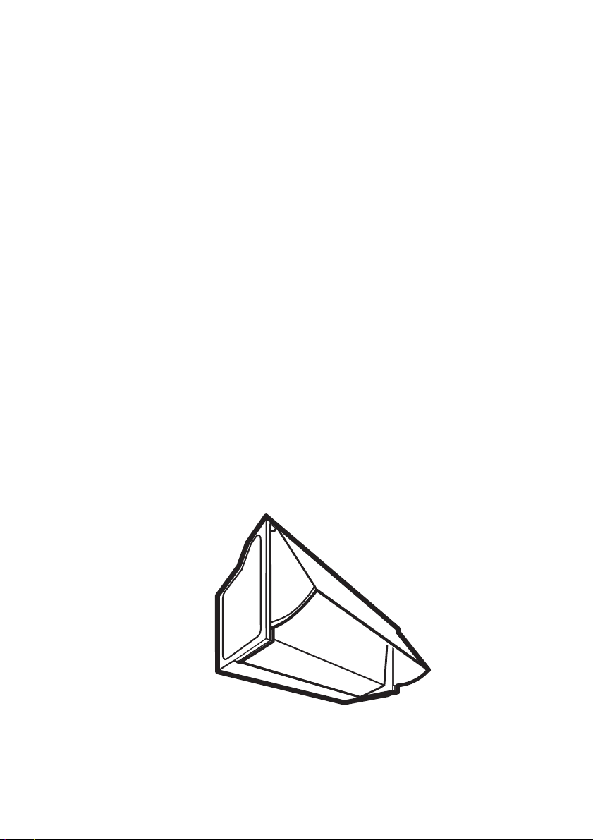
Description of the Appliance
The cooker hood is designed to extract unpleasant odours
from the kitchen, it will not extract steam.
The hood is supplied as an extractor unit and can also be used with
a recirculation mode by fitting a charcoal filter.
You will need an original charcoal filter for this function (Available
from your local Service Force Centre).
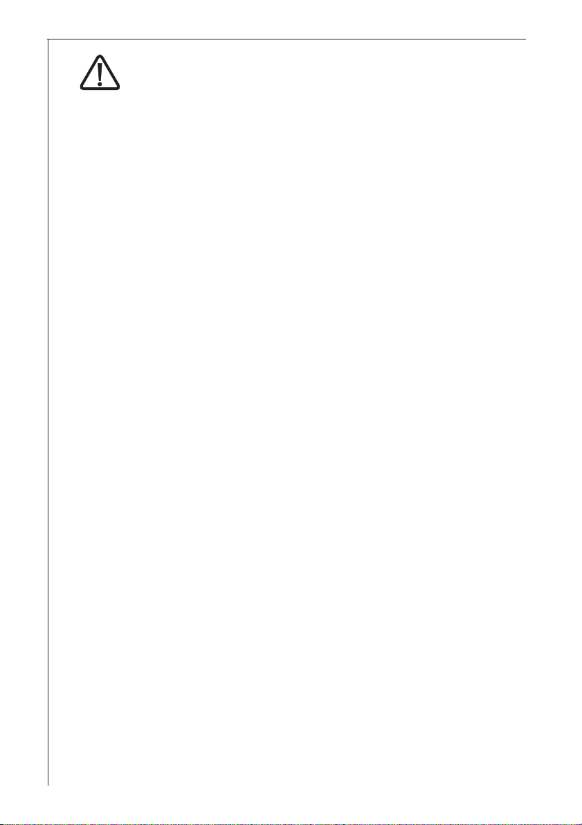
Extraction mode
In this mode fumes are extracted to the outside via a hose
connected to the coupling ring. Fig. 1.
In order to obtain the best performance the hose should have a
diameter equal to the outlet hole.
Depending on your installation the hose can be directed either
towards the ceiling or towards the walls.
Hose
Coupling ring
56
B
Fig. 1
Page 6
Recirculation mode
F
The air is filtered through a charcoal filter and returned to the
kitchen.
You will need an original charcoal filter for the recirculation mode.
(See Special Accessories).
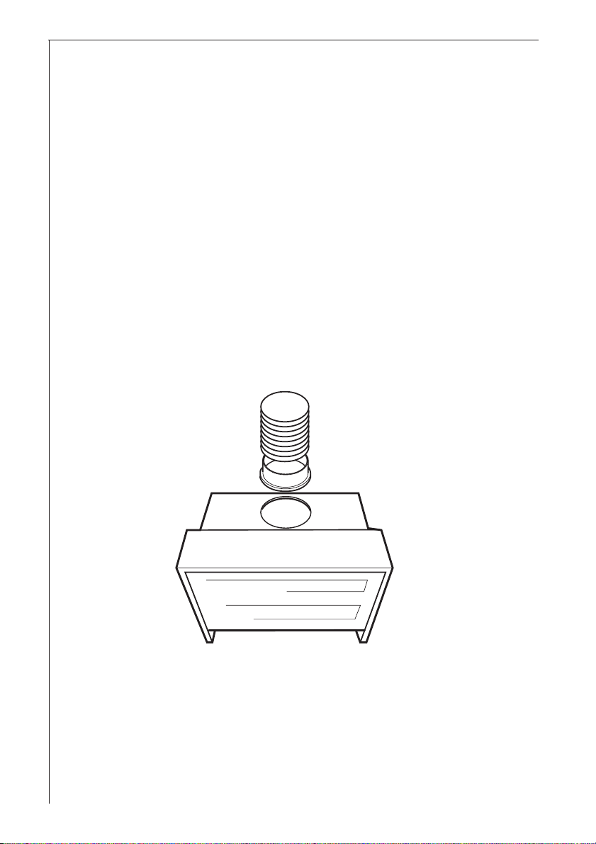
Opening the grid: Move the two sliders towards the centre (in the
OPEN direction) and release the grille downwards. Fig. 2
To refit the grid: it should be inserted above between the
appropriate guides until it latches into place, and after having
propped the grille to the cooker hood also in the lower part move the
two sliders outwards (in the CLOSED direction). Fig. 2.
Arrows
Guides
CLOSED
OPEN
Fig. 2
OPEN
CLOSED
Fig. 3
Place the charcoal filter to cover the grille that protects the extraction
motor. The arrow printed on the charcoal filter must correspond to the
arrow printed on the conveyor. Fig. 3.
Turn the filter clockwise in order to lock the filter into position.
Refit the grid.
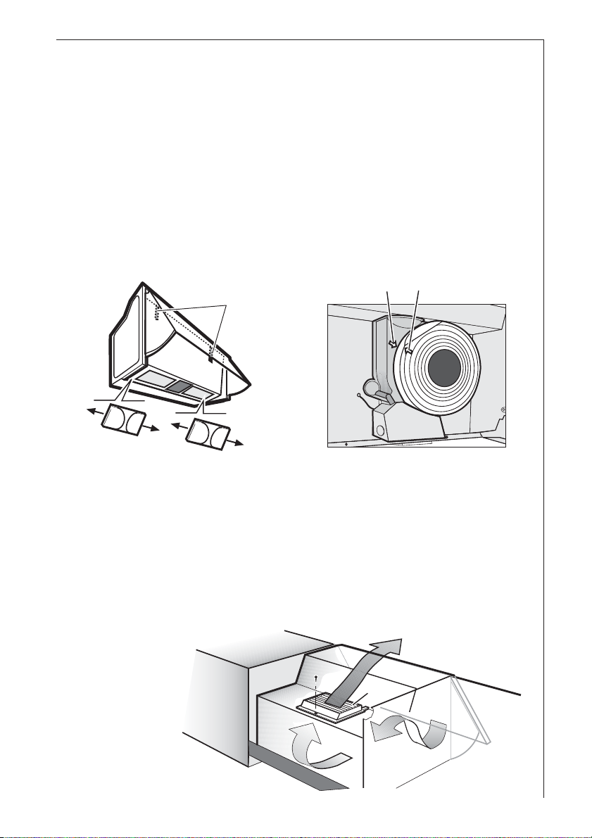
The deflector F must be fitted over the hole B (Fig. 1) fixing it with
the screw provided. Fig. 4.
Fig. 4
57
Page 7
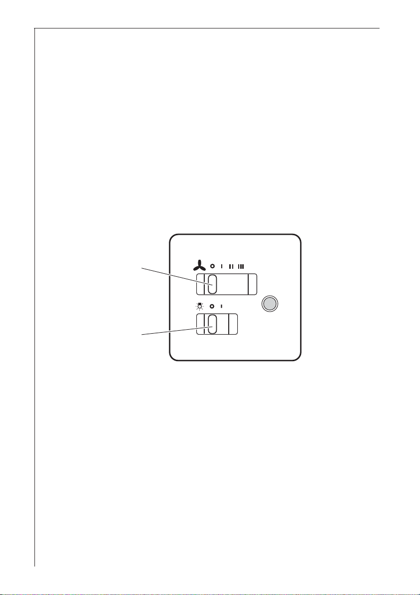
Control Panel
Best results are obtained by using a low speed for normal conditions
and a high speed when odours are more concentrated.
Turn the hood on a few minutes before you start cooking.
The hood should be left on after cooking for about 15 minutes or until
all the odours have disappeared.
The control switches are located on the hoods front panel:
the light switch switches the hood lamp on and off
the motor switch switches the motor on and off, enabling you to
select one of the three different speeds.
Motor switch
Light switch
The hood is also equipped with a micro-switch which can be found
under the lower runner of the visor on the right hand side.
With this micro-switch, the appliance may be automatically switched
on and off by opening and closing the pull-out panel, but only if the fan
speed has already been set and the light button is turned to I.
58
Page 8

Maintenance and Care
The hood must always be disconnected from the electricity
supply before beginning any maintenance work.
Cleaning the hood
Clean the outside of the hood using a damp cloth and a solution of
water and mild washing up liquid.
Never use corrosive, abrasive or flammable cleaning products or
products containing bleach. .
Never insert pointed objects in the motors protective grid.
Only ever clean the switch panel and filter grill using a damp cloth
and mild washing up liquid.
It is extremely important to clean the unit and change the filters at
the recommended intervals. Failure to do so will cause grease
deposits to build up that could constitute a fire hazard.
Grease Filter
The purpose of the grease filters is to absorb grease particles which
form during cooking and it must always be used, either in the
external evacuation or internal recycling function.
The synthetic filter is very thin (approx. 1 mm) and positioned on the
inside of its related support grille.
The filter should be changed once a month.
The grille should be cleaned with luke warm water and non-abrasive
detergent when you change the filter.
The grease filter can be ordered from your local Service Force
Centre.
59
Page 9

Opening the grid
Move the two sliders towards the centre (in the OPEN direction)
and release the grille downwards. Fig. 5.
To refit the grid: it should be inserted above between the
appropriate guides until it latches into place, and after having
propped the grille to the cooker hood also in the lower part move the
two sliders outwards (in the CLOSED direction).
Removing the filter
Remove the stops to take out the filter. Fig. 5.
Clean the inner housing using a hot detergent solution only (never
use caustic detergents, abrasive powders or brushes).
Stops
Guides
60
CLOSED
N
E
P
O
N
E
P
O
CLOSED
Fig.
Page 10

Charcoal filter
The charcoal filter should only be used if you want to use the hood in
recirculation mode.
To do this you will need an original charcoal filter (available from your
local Service Force Centre).
The charcoal filter cannot be washed nor regenerated.
The charcoal filter should be replaced every 12 months under normal
use.
Replacement filters are available from your local Service Force
Centre.
Fitting the charcoal filter:
Remove the grid.
Place the charcoal filter to cover the grille that protects the extraction
motor. The arrow printed on the charcoal filter must correspond to the
arrow printed on the conveyor. Fig. 6.
Turn the filter clockwise in order to lock the filter into position.
Refit the grid.
To remove proceed in the reverse order.
Always specify the hood model code number and serial number
when ordering replacement filters. This information is shown on the
rating plate located on the inside of the unit.
The charcoal filter can be ordered from your local Service Force
Centre.
Fig. 6
Arrows
61
Page 11

Warning
Failure to observe the instructions on cleaning the unit and changing
the filters will cause a fire hazard. You are therefore strongly
recommended to follow these instructions.
The manufacturer declines all responsibility for any damage to the
motor or any fire damage linked to inappropriate maintenance or
failure to observe the above safety recommendations.
Changing the light bulb
Disconnect the cooker hood from the mains supply.
Remove the grid. Fig. 5.
Replace the old bulb with a new one of the same type.
Refit the grid.
If the light does not come on, make sure the bulb has been inserted
in correctly before contacting your local Service Force Centre.
62
Page 12

What to do if
If your appliance fails to work properly please carry out the following
checks.
Symptom Solution
The cooker hood will not start... Check that: The hood is
connected to the electricity
supply.
Check that a fan speed has been
selected
The cooker hood is not working Check that: The fan speed is set
high enough for the task.
The grease filters are clean.
The kitchen is adequately vented
to allow the entry of fresh air.
If set up for recirculation, check
that the charcoal filter is still
effective.
If set up for extraction, check that
the ducting and outlets are not
blocked.
The cooker hood has The safety cut-out device has
switched off during operation... been tripped
Turn off the hob and then wait for
the device to reset.
If the hood has been installed
below the heights indicated in the
installation instructions the motor
will cut-out frequently which will
damage the hood.
If after all these checks, the problem persists, contact your local
Service Force Centre, quoting the model and serial number.
Please note that it will be necessary to provide proof of purchase for
any in-guarantee service calls.
In-guarantee customers should ensure that the above checks have
been made as the engineer will make a charge if the fault is not a
mechanical or electrical breakdown.
63
Page 13

Special accessories
Charcoal filter Type 34
Technical assistance service (not for UK)
You are welcome to telephone our technical assistance service (see list
of technical assistance centres) whenever you need information or in the
unlikely event of a fault.
For service in Australia call 1300 650 020.
When calling, please be ready to specify:
1. The model code number
2. The serial number (E-Nr.)
3. The manufacturing number (F-Nr.)
This information is shown on the registration plate inside the unit
behind the grease filter.
We reserve the right to change specifications and colours as a result of
our policy of continuing technological development.
Service and Spare Parts
In the event of your appliance requiring service, or if you wish to purchase spare parts,
contact your local Service Force Centre by telephoning: 08705 929 929
Your call will be automatically routed to the Service Centre covering your post code
area. For the address of your local Service Force Centre and further information about
Service Force, please visit the website at www.serviceforce.co.uk
Please ensure that you have read the section What to do if.... as the engineer will make
a charge if the fault is not a mechanical or electrical breakdown even the appliance is
under warranty. Please note that proof of purchase is required for in-guarantee
service calls.
Help us to help you
Please determine your type of enquiry before writing or telephoning.
When you contact us we need to know:
Your name Clear and concise details of the fault
Address and post code Name and model of the appliance*
Telephone number E number*
Serial number*
* This information can be found on the rating plate, which can be seen when the grease
filters are removed.
64
Page 14

If you require Customer Service in the Republic of Ireland please contact us at
the address below:
AEG
Electrolux Group (Ire) Ltd
Long Mile Road
Dublin 12
Republic of Ireland
Tel: + 353 (0) 1 4090751
Email: service.eid@electrolux.ie
CUSTOMER CARE DEPARTMENT
For general enquiries concerning your AEG appliance or for further information on AEG
products, please contact our Customer Care Department by letter or telephone at the
address below or visit our website at www.aeg.co.uk
Customer Care Department
AEG
55-77 High Street
Slough, Berkshire
SL1 1DZ
08705 950950 (*)
* calls to this number may be recorded for training purposes.
65
Page 15

Technical Specifications
Dimensions: (in cm):
Height 40
Width 59,9
Depht 27
Maximum absorbed power: 220 W
Motor absorption: 140 W
Lighting: 2 x 40 W
Length of the cable: 150 cm
Electrical connection: 220-240 V
Mounting accessories included
1 allen spanner (for torx screws)
1 template for wall fixing
1 template for fixing to side cabinets
1 template for fixing a furniture door
2 hooks
1 deflector
1 spacer (lower bracket)
2 screws 3.5 x 9.5 e 2 washers (to affix the spacer to the cooker hood)
4 dowels Ø 8 mm
2 round head screws 5 x 45 (for spacer wall fixing)
2 flat head screws 5 x 45 (for hooks)
1 screw 2.9 x 9.5 (to fix deflector on hood outlet hole)
2 screws 4.2 x 35 (to fix hood under the cabinet ceiling)
4 screws 4.5 x 16 (for fixing to side cabinets)
8 screws 4.5 x 13 (for fixing a furniture door).
1 coupling ring Ø 100 mm
1 coupling ring Ø 120 mm
2 screws 2,9 x 13 (to fix deflector on the cabinet ceiling)
66
Page 16

Electrical connection (not for UK)
Safety warnings for the electrician
Before connecting the appliance to the power supply, check that the
voltage indicated on the rating plate corresponds to the mains power
supply available. Appliances fitted with a plug can be connected to any
standard power socket within easy access.
Should it be necessary to provide a fixed connection, the hood must
only be installed by an electrician authorised by the local electricity
board. When installing, an omnipolar disconnector with a distance of at
least 3 mm between contacts must be provided.
Fixed connection of the appliance must only be carried out by an
authorised electrician.
Electrical connection for UK only
Safety warnings for the electrician
Connect the hood to the mains supply via a double pole switch
which has 3 mm minimum separation between the contacts.
The switch must be accessible at all times.
The following is valid in the United Kingdom only:
- the wire which is coloured blue must be connected to the terminal
which is marked with the letter N or coloured black, -
- the wire which is coloured brown must be connected to the terminal
which is marked with the letter L or coloured red.
67
Page 17

Installing the hood between cabinets
Use the template N2, position the diagram on the anterior borders of
the cabinet (right cabinet must remain visible on the letter B of the
drill holes diagram) (left cabinet must remain visible on the letter
C of the template) drill the holes IRRESPECTIVE OF THE
THICKNESS OF THE CABINET DOOR.
Fasten the cooker hood with 4 screws (Fig. 7 ,P), place the
connection ring and discharge pipe (or deflector if supplied) to the
cooker hood outlet (see Use section), mount the lower bracket
(Fig. 7-9,Q) to the cooker hood with two screws and plastic washers
(Fig. 9,T).
Attention! If required, the hood can be fixed to an existing cabinet top
with two screws, be sure to leave passage for exhaust hose (or for
recycled air flow) and electrical supply cable. Fig. 8a-b.
68
C
N2
Fig. 7
B
N
2
P
P
Fig. 8a - Extraction mode
Q
Fig. 8b - Recirculation mode
Page 18

Installing the hood to the wall
Use the template N1, drill as indicated, insert two hooks in the upper
drill holes (Fig. 9,R1) and two dowels in the lower drill holes (Fig.
9,R2).
Fasten the lower bracket to the wall with two screws (Fig. 7-9,Q).
Hang the cooker hood on the wall, regulate the position of the cooker
hood (Fig. 9 - screws S1 for vertical regulation, screws S2 for depth
regulation)
Place connection ring and discharge pipe (or deflector if supplied) to
the cooker hood outlet (see Use section), fasten the cooker hood to
the lower bracket (Fig. 7-9,Q) with two screws and plastic washers
(Fig. 9,T).
Access to the screws that secure the lower bracket may be through
the drill holes located inside the cooker hood (Fig. 9,U).
R1R1
N1
R2
R2
Q
Q
S1
S2
U
U
T
T
Fig. 9
69
Page 19

Fixing a furniture door to the visor
Remove the extraction grille.
Remove the visor (freeing the locking releases I-Fig. 10).
I
Apply the template N3 on the rear of the furniture door (Fig. 11,J-the
arrow on the diagram should face the upper border of the furniture
door), perform blind holes as indicated (K-Fig. 11).
Place the visor over the furniture door and affix with 8 screws (Fig.
11,L).
Refit the cover on the cooker hood firstly in the upper track (Fig. 12-
M1), then in the lower track (Fig. 12-M2).
Ø 2,5mm x 6mm max
N3
K
Fig. 10
6mm
I
J
L
L
M1
M2
M1
M2
Fig. 11
Where the cooker hood is provided with revolving locking releases
these should be turned in the opposite direction of the release to
ensure that the visor is not unintentionally released during normal
use of the cooker hood. Fig. 10.
70
Fig. 12
Page 20

71
Page 21

From the Electrolux Group. The world´s No.1 choice.
The Electrolux Group is the world´s largest producer of powered appliances for kitchen,
cleaning and outdoor use. More than 55 million Electrolux Group products (such as refrigerators,
cookers, washing machines,vacuum cleaners, chain saws and lawn mowers) are sold each
year to a value of approx. USD 14 billion in more than 150 countries around the world.
AEG
55-77 High Street
SLOUGH
Berks
SL1 1DZ
http://www.aeg.co.uk
AEG Hausgeräte GmbH
Postfach 1036
D-90327 Nürnberg
http://www.aeg.hausgeraete.de
© Copyright by AEG
LI2J2A Ed. 12/04
 Loading...