

GB
GENERAL INFORMATION
DESTINED TO THE END USER
ENVIRONMENT PROTECTION
Packing disposal
Sort packing into different materials (cardboard, polystyrene
etc.) and dispose of them in accordance with local waste
disposal laws.
This appliance complies with the following European Directives:
- 73/23/EEC regarding "Low Voltage".
- 89/336/EEC regarding "Electromagnetic Disturbances".
- 90/396/EEC regarding “Gas appliances”
- 89/109/EEC regarding "Materials in contact with food"
- Moreover the abov e mentioned Directiv es comply with Directive
93/68/EEC.
- This household appliance has been designed for cooking and
it must therefore be used for this purpose only.
DEAR CUSTOMER,
• Carefully read these instructions before using the appliance and
keep them for future consultation.
• Keep potentially hazardous packaging (plastic bags , polystyrene
etc.) out of the reach of children.
WARRANTY
Your new appliance is covered by a warranty.
The warranty certificate is herewith enclosed. If it is missing, ask
the retailer for it indicating purchasing date, model, and data plate
number which are printed on the data nameplate identifing the
appliance.
Keep the part destined to you, and in case of necessity, show it
to the Technical Service together with the receipt bill.
If you do not follow this procedure, the technical service will be
compelled to charge you with all the fees of each e ventual reparation.
You can find the original spare parts only in our Technical Service
and Spare Parts Authorised Centres.
RECCOMANDATIONS AND PRECAUTIONS
FIRST PART
ATTENTION:
- Before using the appliance, do not forget to remove the plastic
films protecting some parts of the appliance (facia-panel, parts
in stainless steel, etc.)
- Do not use the appliance as a space heater.
- When the appliance is not in use, we recommend
the current and to close the gas general tap.
IN CASE OF FIRE:
• In case of fire, close
pipe line, disconnect current
oil in any case.
• Do not store flammable products or aerosol containers near the
burners, and do not vaporize them near lighted burners.
FOR YOUR SAFETY AND THE ONE OF YOUR CHILDREN.
• Do not store items that are attractive to children above or near
the appliance.
• Keep children well away from the appliance: do not forget that
some parts of the appliance or of the pans become very hot and
dangerous during use, and also for all the time necessary to cool
down.
• In order to avoid any unintentional f a ll down, pan handles should
be turned to the back of the cooker, not out to the room or over
adjacent burners.
• When cooking, do not use clothes with large flaving and
flammable sleeves; in case of firing you can suffer very serious
harms.
WARNING - OVEN:
When the oven or the grill are in use, accessible parts can
become very hot; it is necessary to keep children well away
from the appliance.
- Never cook food on the lower wall of the oven.
- In case of careless use, in proximity of the oven door hinges,
there is hurt danger.
- Do not let children sit down or play with the oven door. Do not
use the drop down door as a stool to reach above cabinets.
immediately the main valve of the gas
and never pour water on firing
to disconnect
TECHNICAL AFTER SALES SERVICE
Before leaving the f actory, this appliance has been tested and set
up by skilled personal, in order to give the best performance
results.
Each reparation or set up that could be necessary afterwards,
must be carried out with a great care and attention.
For this reason, we reccommend you to k eep alw a ys in touch with
the Sales Centre or with our nearer After Sales Service. Specify
always the kind of problem and the model of your appliance.
WARMING CABINET
You must not place inflammable materials or plastic utensils in the
warming cabinet (placed below the oven).
FOR APPLIANCES WHIT GLASS COVER LID
While using the appliancemake sure that the glass lid does not
touch any pan. After use ne v er close the glass lid while the burners
or the electric hotplates are still hot.
12 12

GB
GB
V
Fig. 13
Fig. 15
Fig.14
A
- To disassemb le the control panel, unscrew the 4 internal screws
(B) fixing the control panel to the oven face ( fig 16 ).
Fig. 16
B
GREASING OF TAPS
If a tap becomes hard to be turned, grease it using a specific
grease withstanding high temperatures. Act as follows: switch the
appliance off, and close the gas tap open the work-top and
disassemble also the control panel as described on the previous
paragraph. Unscrew the two fixing screws from the burner body
(see picture) and remove the cone.
Clean the cone and its slot by means of a cloth soaked with diluent.
Slightly grease the cone with the relevant grease, put it in its slot,
and turn it some times. Remove the cone again, remove the
exceeding grease making sure the gas entries are not obstructed
by grease residuals. Assemble ev erything carefully in the opposite
direction check the connection seal by means of soapy water.
TAPS REPLACEMENT
Act as follows: switch the appliance off, and close the general tap
open the work-top and disassemble also the control panel as
described on the previous paragraph. Unscrew screw nut D of the
gas tube supplying the burner. Unscrew screw V fixing the tap to
the bridle and remove it (see picture).
Note: Ev ery time the tap is replaced, it is necessary to replace the
seal gasket too check the connection seal by means of soapy
water (see picture).
D
V
For your safety
The product should only be used for its intended purpose which
is for the cooking of domestic foodstuffs.
Under no circumstances should any external covers be removed
for servicing or maintenance except by suitably qualified personnel.
Do’s and Do Not’s
Do make sure you understand the controls before using the
cooker.
Do check that all controls on the cooker are turned off after use.
Do always stand back when opening an oven door to allow heat
to disperse.
Do always use dry, good quality oven glov es when remo ving items
from the oven.
Do take care when removing items from the ov en, as the contents
may be hot.
Do always keep the oven doors closed when the cooker is not in
use.
Do always place pans centrally o v er the hob b urners and position
them so that the handles cannot accidentally be caught or knocked
or become heated by other burners.
Do keep the cooker clean, as a build up of grease or fat from
cooking can cause a fire.
Do always allow the cooker to cool before cleaning.
Do always f ollow the basic principles of f ood handling and h ygiene
to prevent the possibility of bacterial growth.
Do always keep ventilation slots clear of obstructions.
Do always turn off the electricity before cleaning or replacing an
oven lamp.
Do not allow children near the cooker when in use as all surfaces
will become hot during and after cooking.
Do not allow anyone to sit or stand on any part of the cooker.
Do not heat up unopened food containers as pressure can build
up causing the container to burst.
Do not store chemicals , food stuffs, pressurised containers in or
on the cooker, or in cabinets immediately above or next to the
cooker.
Do not fill a deep fat frying pan more than1/3 full of fat, oil, or use
a lid.
DO NOT LEAVE UNA TTENDED WHILE COOKING.
Do not place flammable or plastic items on or near the hob
burners.
Do not use proprietary spillage collectors on the hob burners.
Do not use the cooker as a room heater.
Do not dry clothes or place other items over or near to the hob
burners or oven doors.
Do not wear garments with long flowing sleeves whilst cooking.
Do not place inflammable materials in the oven or the compartment
below the oven.
Do not allow fat or oil to build up in the oven trays, grill pan or
oven base.
Do not place cooking utensils or plates onto the oven base.
Do not grill food containing fat without using the grid.
Do not cover the grilling grid with aluminium foil.
Do not place hot enamel parts in water, leave them to cool first.
Do not allow vinegar, coffee, milk, saltwater, lemon or tomato
juice to remain in contact with enamel parts (inside the oven and
oven trays).
Do not use abrasive cleaners or powders that will scratch the
surface of the stainless steel and the enamel.
WORK-TOP USE
FIRST PART
USING GAS BURNERS
The following symbols are on the control panel ne xt to each knob:
- Black circle gas off
- Large flame maximum setting
- Small flame minimum setting
The minimum position is at the end of the anti-clockwise rotation
of the knob. All operation positions must be chosen between the
positions of max. and min., ne ver choose them between max. and
off.
MANUAL IGNITION
To turn on a burner, approach a match to it, press the knob
corresponding to the selected burner and turn it anticlockwise to
the max position.
ELECTRIC IGNITION (optional)
To turn on a burner, press the knob corresponding to the selected
burner and turn it anticlockwise to the max position; simultaneously
pressing the electric ignition button on the control panel marked
with symbol
In case there is no electric current, the burner can also be lighted
using a match.
AUTOMATIC ELECTRIC IGNITION (optional)
To turn on a burner, press the knob corresponding to the selected
burner and turn it anticlockwise to the max position. Keeping the
knob pressed, the electric automatic ignition of the burner will be
started up.
In case there is no electric current, the burner can also be lighted
using a match.
APPLIANCES WITH SAFETY V AL VE (optional)
Follow the same procedure described above to ignite the b urners.
In this case, however, once you ha ve turned the knob to the open
setting, hold it pressed in for 10 seconds.
If for any reason the burner flame goes out, the safety valve
automatically shuts off the gas supply to the burner in question.
ENERGY SAVING TIPS
• The diameter of the pan bottom should be the same as that of
the burner. The b urner flame must never come out from the pans
diameter.
• Use flat-bottomed pans only.
• Whenever possible, keep a lid on the pan while cooking.
You will not need as much heat.
• Cook vegetables, potatoes, etc. with as little water as possible
to reduce cooking times.
.
BURNERS PANS
Ø min. Ø max
RAPIDE 180 mm 220 mm
SEMIRAPIDE 120 mm 200 mm
AUXILIARY 80 mm 160 mm
TRIPLE CROWN 220 mm 260 mm
USE OF THE ELECTRIC OVEN
FIRST PART
The first time the oven is used, it may giv e off acrid smells, caused
by the first heating of isolating panels glue surrounding the oven
(it is necessary to heat up the oven at the maximum
temperature for about 30-40 minutes with closed door).
It is something normal, and in case it will occur, wait for the smok e
to stop before introducing the food into the oven.
The oven is fitted with: a rod shelf for cooking food contained in
oven dishes or placed directly on the rod shelf itself, a drip-tray
for cooking sweets, biscuits, pizzas, etc., or for collecting juices
and fats from food cooked directly on the rod shelf.
Note: The following tables give the main points for cooking some
of the most important dishes. The cooking times recommended
in these tables are approximate. After a fe w tries, we are sure that
you will be able to adjust the times to get the results you want.
Conventional cooking table TAB.B
Dish Temp. °C. Minutes
Fish 180-240 acc. to size
Meat
Roast ox 250 30 per kg.
Roast veal 200-220 30 per kg.
Chicken 200-240 50 about
Duck and goose 220 acc. to weight
Leg of mutton 250 30 per kg.
Roast pork 250 60 per kg.
Soufflets 200 60 per kg.
Sweets (pastries)
Tea-cake 160 50-60
Sponge finger 160 30-50
Shortcrust pastry 200 15
Puff pastry 250 15
Fruit flan 200-220 30
Meringues 100 60
Quiches, etc. 220 30
4 quarters 120-140 60
Buns 160-180 45
Fan oven cooking table TAB. C.
Dish Temp. °C. Minutes Weight kg.
Firs courses
Lasagne 200-220 20-25 0,5
Oven pasta 200-220 25-30 0,5
Creole rice 200-230 20-25 0,5
Pizza 210-230 30-45 0,5
Meat
Roast veal 160-180 65-90 1-1,2
Roast pork 160-170 70-100 1-1,2
Roast ox 170-190 40-60 1-1,2
Roast beef joint 170-180 65-90 1-1,2
Roast fillet beef (rare) 180-190 40-45 1-1,5
Roast lamb 140-160 100-130 1,5
Roast chicken 180 70-90 1-1,2
Roast duck 170-180 100-160 1,5-2
Roast goose 160-180 120-160 3-3,5
Roast turkey 160-170 160-240 5 approx.
Roast rabbit 160-170 80-100 2 approx.
Roast hare 170-180 30-50 2 approx.
Fish 160-180 acc. to weight
Sweets (pastries)
Fruit flan 180-200 40-50
Plain sandwich cake 160-180 35-45
Sponge sandwich cake 200-220 40-45
Sponge cake 200-230 25-35
Currant cake 230-250 30-40
Buns 170-180 40-60
Strûdel 160 25-35
Cream slices 180-200 20-30
Apple fritters 180-200 18-25
Sponge finger pudding 170-180 30-40
Sponge finder biscuits 150-180 50-60
Toasted sandwiches 230-250 7
Bread 200-220 40
20 13
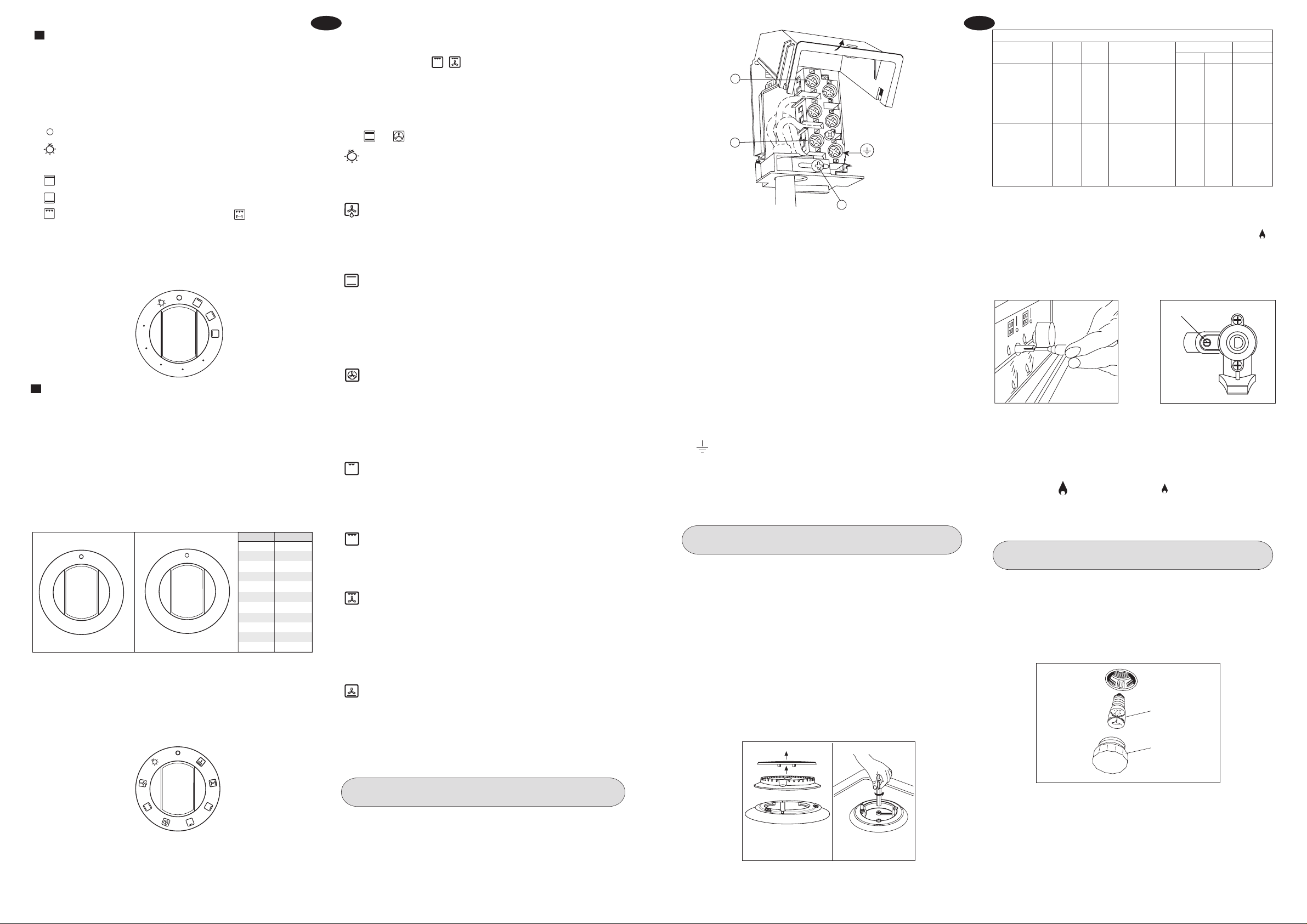
1 – NATURAL CONVECTION OVENS
The oven is fitted with:
• a lower heating element;
• an upper heating element.
It is possible to select the desired temperature into the oven by
turning clockwise the thermostat knob and depending on the
models, one or more functions:
Oven off
Oven light
60 ÷ max Upper + lower heating element on
Upper heating element on
Lower heating element on
Grill element on ( turnspit optional )
WARNING - GRILL:
Always use the grill with oven door half-open (at the first hinge
release), and with knobs protection installed, as per the specific
instructions provided in the grill use.
0
6
0
9
0
3
1
0
7
1
m
a
x
2
0
0
2 – MULTIFUNCTIONAL O VEN
The oven is fitted with:
• a lower heating element;
• an upper heating element;
• a circular heating element surrounding the fan.
N.B.: Always set the temperature on the thermostat knob before
selecting any of the functions.
Oven thermostat knob
To obtain an oven temperature betw een 60°C and MAX°C (or 0 - 11),
turn the knob clockwise.
Pos.knob
Temp.in °C
1 60
m
a
x
0
6
0
8
0
0
1
5
2
1
2
2
5
2
0
0
1
7
5
1
5
0
1
2
3
4
1
7
6
5
1
1
0
9
8
2 80
3 100
4 120
5 140
6 155
7 175
8 190
9 210
10 230
11 250
Oven commutator knob
Depending on the type of oven, it is possible to select one of the
following functions turning the commutator knob clockwise.
.
GB
Use of the oven
Note: ovens with separate thermostat and commutator.
When the functions are used, place the thermostat knob
between 180 ÷ 200°C as maximum temperature.
ATTENTION:
The temperature shown on the control panel corresponds to the
temperature in the oven centre only when the functions selected
are or
.
When you turn the control knob to this position, the light will be
on for all the following operations.
Defrosting with fan
The air at ambient temperature is distributed inside the oven for
defrosting food very quickly and without proteins adulterations.
The thermostat knob must be placed on the maximum position.
Natural convection
Both the lower and upper heating elements operate together.
This is the traditional cooking, very good for roasting joints, ideal
for biscuits, baked apples and crisping food.
You obtain very good results when cooking on a shelf adjusting
the temperature between 60 and MAX°C.
Fan oven
Both the fan and the circular heating element operate together.
The hot air adjustable between 60 and MAX°C is e venly distrib uted
inside the oven. This is ideal for cooking several types of food
(meat, fish) at the same time without affecting taste and smell.
It is indicated for delicate pastries.
Medium grill
It is indicated for grilling and gratinating small quantities of traditional
food.
The thermostat knob must be placed on the maximum position.
Total grill
It is indicated for grilling and gratinating traditional food.
Turn the thermostat control knob to the 200°C position.
Fan assisted total grill
The air which is heated by the grill heating element is circulated
by the fan which distributes the heat on the food.
The fan assisted grill replaces perfectly the turnspit. You can obtain
very good results also with large quantities of poultry, sausage,
red meat. Turn the thermostat control knob to the 200°C position.
Air forced lower heating element
The air which is heated by the lower heating element is circulated
by the fan which distributes the heat on the food.
This function can be used to sterilize food. This function can be
used between 60 and MAX°C
L
N
1
2
3
4
5
A
IMPORTANT
The wires in the mains lead are coloured in accordance with the
following code:
GREEN AND YELLOW......EARTH
BLUE.................................NEUTRAL
BROWN.............................LIVE
REPLACEMENT OF THE CABLE
In case the cable is damaged, replace it in accordance with the
following instructions:
- open the box of the supply board as described on the picture
below;
- unscrew screw “A” fixing the cable;
- replace the cable with one of the same lenght and in accordance
with the features described on the table; switch the appliance
off, and close the gas tap
- the ‘green-yellow” earth wire must be connected to the terminal
“ “ and it must be about 10 mm longer thean the live wires;
- the “blue” neutral wire must be connected to the terminal marked
with letter “N”;
- the live wire must be connected to the terminal marked with letter
“L”.
GAS ADJUSTMENT
Conversion to LPG
Always isolate the cooker from the electricity supply, turn off the
gas supply temporarily and proceed as follows.
- change the injectors,
- adjust the minimum flow of the burners.
REPLACEMENT OF WORK-TOP INJECTORS
In order to change the work-top injectors, it is necessary to act as
follows: remove the grids, remove burners and flame-spreaders
(see fig.A), change the injector (see fig.B) and replace it with
another one suitable for the new type of gas (see table D). Reassemble ev erything in the opposite direction, paying attention to
place the flame-spreader in the right way on the burner.
GB
TAB. D GENERAL INJECTORS TABLE
Kind of gas mbar Nozzle Burners Power Watt Consum.
NATURAL 20 97 -Semi rapide 1750 480 167 l/h
G.P.L. 30 85 -Rapide 3000 750 219 g/h
BUTANE 28 65 -Semi rapide 1750 480 128 g/h
PROPANE 37 50 -Auxiliary 1000 330 73 g/h
N. type max. min. max.
115 -Rapide 3000 750 286 l/h
72 -Auxiliary 1000 330 95 l/h
128 -Triple crown 3300 1300 298 l/h
120 - Fish 2900 1500 262 l/h
93 -Triple crown 3300 1300 241 g/h
85 - Fish 2900 1500 211 g/h
MINIMUM FLOW ADJUSTMENT FOR WORK-TOP TAPS
In order to adjust the minimum, act as follows: switch the burner
on, and turn the knob towards the minimum flow position
Remove the knob from the tap , introduce a little scre wdriver in the
tap rod (fig. 11).
Attention: in taps with security valv e , the minimum adjusting scre w
“Z” is placed outside the rod tap (fig. 12).
Z
Fig. 11
Fig. 12
Unscrew the adjusting screw in order to increase the flow or scre w
it to decrease the flow.
The right adjustment is obtained when the flame has a length of
about 3 or 4 mm.
For butane/propane gas, the adjusting scre w must be tight screw ed.
Make sure that the flame does not go out passing quickly from
the max. flow
to the minimum flow .
Assemble the knob again.
APPLIANCE MAINTENANCE
WARNINGS
Isolate the cooker from the electricity supply before attempting to
replace the oven lamp.
The oven lamp used is of a special type withstanding high
temperatures. To replace it, act as follows: disassemble the
protecting glass (A) and replace the burnt lamp with one of the
same type. Reassemble the protecting glass.
E 14
25 W - 230 V~
T300°C
A
.
Note:
All the functions mentioned above switch the o v en internal light on. A
warning light on the control panel will stay lit until the temperature is
reached; after it will light up intermittently. Alwa ys use the ov en with the
oven door closed
USE OF THE ELECTRIC GRILL
The appliance is foreseen to operate the grill with half-open door
(fig. 2) and with the grid on the third shelf from the oven bottom,
at about 12 cm from the surface, and with the deflector placed as
in (fig. 2). The user can change the shelves, depending on his
personal whishes and on the different food.
Geat the oven 5 minutes before introducing the food.
14 19
AB
DISASSEMBLE OF WORK-TOP
In case it is necessary to repair or replace the inside components,
act as follows:remove the glass lid from its position slipping off it
upwards.
Remove the grids, remove burners and flame-spreaders (see
fig. 13), unscrew the visible screws “V” placed on the work-top
(see fig. 14). Disassemble the work-top by unscrewing the 4 rear
screws “A” (see fig. 15 ).

Fig. 8
GAS CONNECTING
This appliance shall be installed in accordance whit the regulations
in force and only in a well-ventilated space. Read the instructions
before installing or using this appliance.
IMPORTANT
Conversion for use on and other gases must only be undertaken
by a qualified person. For information for use on other gases
contact your local Service Centre.
The cooker must be installed by a qualified person in accordance
with then local rules
Failure to install the appliance correctly could invalidate any
manufacturers warranty and lead to prosecution under the above
quoted regulations.
Provision for Ventilation
The room containing the cooker should have an air supply in
accordance with local rules. The room must have an opening
windows or equivalent; some rooms ma y also require a permanent
vent. If the room has a volume between 5 and 10m
an air vent of 50cm
opens directly to the outside. If the room has a v olume of less than
3
, it will require an air vent of 100cm2 effective area. If there
5m
2
effective area unless it has a door which
are other fuel burning appliances in the same room. Ensure that
the room containing the cooker is well ventilated, keep natural
ventilation holes or install a mechanical ventilation device
(mechanical cooker hood). Prolonged intensive use of the appliance
may call for additional v entilation, f or e xample opening of a window,
or more effective ventilation, for example increasing the level of
mechanical ventilation where present. This cooker is not fitted with
a device for discharging the products of combustion. Ensure that
the ventilation rules and regulations are followed. Excess steam
from the oven, vents out at the top back edge of the cooker, so
make sure that the walls behind and near the cooker are resistant
to heat, steam and condensation. Your cooker must stand on a
flat surface so that when it is in position the hob is level. When in
position check that the cooker is level by using a spirit level and
adjust the 2 feet at the rear and the 2 feet at the front if necessary.
It is important that the cooker is stable and level for the overall
cooking performance.
Remember that the quantity of air necessary for combustion must
never be less than 2m
3
/h for each kW of power (see total power
in kW on the appliance data plate).
Gas Safety (Installation & Use) Regulations
It is the law that all gas appliances are installed by competent
persons in accordance with the current edition of the Installation
& Use Regulations. It is in your interest and that of safety to
ensure compliance with the law.
3
, it will require
GB GB
Gas Connection
Prior to installation, ensure that the local distribution conditions
(nature of the gas and gas pressure) and the adjustment conditions
are compatible. The adjustment conditions for this appliance are
stated on the rating plate which can be found on the back cover.
This appliance is not designed to be connected to a combustion
products evacuation device. Particular attention should be given
to the relevant requirements regarding ventilation.
Connection to the cooker should be made with an approved
The grill must be used with the door half-open (see fig.2 A).
Fit the deflector S onto the centring pins N on the top of the oven
opening (fig.2 B ). Then gently close the oven door against the
deflector.
Some models are designed for the grill to be used with the oven
door completely closed.
Make sure that the cooker is designed for this type of operation.
warning: In this case the deflector S shown in fig. 2 B, is not
supplied.
appliance flexible connection to local rules. Models for use with
LPG should be fitted with a hose suitable for LPG and capable of
withstanding 50mbar pressure. A length of 0.9 to 1.25m is
Fig. 2 A Fig. 2 B
recommended. The length of hose chosen should be such that
when the cooker is in situ, the hose does not touch the floor.
The temperature rise of areas at the rear of the cooker that are
likely to come in contact with the flexible hose do not exceed 70
0
C.
N
Gas pressure may be checked on a semi-r apid hob burner . Remo ve
the appropriate injector and attach a test nipple. Light the other
burners and observe that the gas pressure complies with the gas
S
standards in force.
Certain types of cookers can be set for sypply both on the right
and lefthand side. In this case it is sufficient to re verse the position
of the cad nipple reducer. At the end make sure than there is no
leakage of gas.
USE OF THE TURNSPIT
TURNSPIT multilpe
For utilization of the turnspit follow the instructions described.
- Thread the chicken or the cubes of meat for roasting on the
spit L , ensuring that it is gripped safely between the two forks
F and balancing it properly to avoid unnecessary strain on the
trasmission R (fig 3).
- Put the spit on the support G, after having introduced its
opposite end in the socket P of the transmission R (fig 3)
INLET STOP
- Put the support G completely into the oven so that the bar I
goes into the socket H of the turnspit motor M (fig 3A).
- Place the drip-tray with some water under the turnspit, on the
lowest level
The appliance is designed for the grill to be used with the door
open ( Fig. 2 A ).
Fit the deflector S onto the centring pins N on the top of the
oven opening(fig.2 B ).
- when removing the spit, wear oven mitts, pull out support G
and use the handgrip A operating in the contrary way (fig 3B).
ELECTRICAL CONNECTION
This appliance must be installed by a qualified person in
accordance with the latest edition of the IEE Regulations and
in compliance with the manufacturer instructions.
Ensure that the voltage is the same as that stated on the rating
plate. The rating plate can be found on the back cover .
Fig. 3
Fig. 3B
RL F
P
M
G
I
F
Fig. 3 A
H
R
G
WARNING! THIS APPLIANCE MUST BE EARTHED
The cooker must be connected to a suitable cooker control unit
incorporating a double pole switch having a contact separation
of at least 3mm in all poles, which is adjacent to (but not abov e),
L
A
and not more than1.25m away from the cooker and capable of
electrical isolation.
We recommend that the cooker circuit is rated to 20amps.
Cable type HO5 RRF 3 X 1.5 mm
2
TURNSPIT single
For utilization of the turnspit follow the instructions described .
- Put the food in spit L (see fig.3 C), paying attention to block it
within the two forks F and to balance it, in order to avoid any
Connecting the mains cable
Open the mains terminal block cover as shown, unscrew screw
“A” the cable clamp and unscrew (not fully) the screws in the
mains terminal block “L N E” which secure the three wires of the
mains cable. Fit the cable and refit screw “A” the cable clamp.
Allow sufficient cable length for the cooker to be pulled out for
cleaning, but do not let it hang closer than 50mm (2”) to the floor.
The cable can be looped if necessary, but make sure that it is not
kinked or trapped when the cooker is in position.
unnecessary effort in motor R.
- Put the spit on support G, after having put its opposite end into
hole P of motor R.
- Place the drip-tray with a little water under the spit.
- Start up motor R and turn the grill on.
Fit the deflector S onto the centring pins N on the top of the
oven opening (vedi fig.2 A-B).
- To remote the spit, operate in the opposite direction using knob
S and protecting glove in isolating wool (fig.3 C).
R
Fig. 3C
P
2
2
F
L
S
G
1
1
INSTRUCTIONS FOR USE OF CONTROL DEVICES
(ACCORDING T O THE MODELS)
FIRST PART
“LED” PROGRAMMER (Fig. 4)
Features
24 hours clock with automatic programme and minutes counter.
Functions
Cooking time, cooking end time, manual position, clock,
minutes counter, times to be set up to 23 hours 59 minutes.
Display
4-figures, 7-segments diplay for cooking times and time of day.
Cooking time and manual function = saucepan symbol
Automatic function = AUTO
Minutes counter = bell symbol
The symbols light up when the corresponding functions are
selected.
Minute timer
A
U
T
O
Fig. 4
Setting
To set, press and release the desired function, and within 5
seconds set the time with + and - buttons.
+ and - buttons.
The + and - buttons increase or decrease the time at a speed
depending on how long the button is pressed.
Setting the time
Press any two buttons (cooking time, end time , minutes counter)
at the same time, and + or - button to set the desired time. This
deletes any previously set programme . The contacts are s witched
off and the AUTO symbol flashes.
Manual use
By pressing the manual button the relay contacts switch on, the
AUTO symbol switches off and the saucepan symbol lights up.
Manual operation can only be enabled after the automatic
programme is over or it has been cancelled.
Automatic use
Press the cooking time or end time button to switch automatically
from the manual to the automatic function.
Cooking time
Cooking end
Manual
Subtract time
Add time
18 15

Semi-automatic use with cooking time setting
Press the cooking time button and set the desired time with + or
-. The AUTO and cooking time symbols light up continuously. The
relay switches on immediately. When the cooking end time
corresponds to the time of day, the relay and cooking time symbol
switch off, the sound signal rings and the AUTO symbol flashes.
Semi-automatic use with end time setting
Press the end time button. The time of day appears on the display.
Set the cooking end time with + button. The AUTO and cooking
time symbols light up continuously. The relay contacts switch on.
When the cooking end time corresponds to the time of day, the
relay and the cooking time symbol switch off. When the cooking
time is up, the AUTO symbol flashes, the sound signal rings and
both the relay and the cooking time button switch off.
Automatic use with cooking time and end time setting
Press the cooking time button and select the length of the cooking
time with + or - button. The AUTO and cooking time symbols light
up continuously. The relay switches on. By pressing the cooking
end time button the next cooking end time appears on the displa y.
Set the cooking end time with + button. The relay and the cooking
time symbol switch off.
The symbol lights up again when the time of day corresponds to
the cooking start time. When the cooking time is up, the AUTO
symbol flashes, the sound signal rings, the cooking time symbol
and the relay switch off.
Minutes counter
Press the minutes counter button and set the cooking time with
+ or - button.
The bell symbol lights up when the minutes counter is operating
When the set time is up, the sound signal rings and the bell symbol
switches off.
Sound signal
The sound signal starts at the end of a programme or of the
minutes counter function and it lasts for 15 minutes.
To stop it, push any one of the functions buttons.
Start programme and check
The programme starts 4 seconds after it has been set.
The programme can be checked at any time by pressing the
corresponding button.
Setting error
A setting error is made if the time of day on the clock falls within
the cooking start and end times.
To correct the setting error, change the cooking time or cooking
end time.
The relays switch off when a setting error is made.
Cancelling a setting
To cancel a setting, press the cooking time button and then press
the - button until 00 00 appears on the display.
A set programme will automatically cancel on completion.
GB GB
PROGRAMMER WITH COOKING END TIME (Fig.6)
For a manual operation of the programmer, turn the knob
anticlockwise to
Adjust the cooking time by turning the knob clockwise.
Select the cooking time with the relevant knob (max.120 min.).
The oven will switch off automatically when the cooking is up.
.
Before cleaning the appliance
CARE AND MAINTENANCE
, disconnect the gas general
tap and unplug the appliance or disconnect power at the
s
t
o
p
0
0
1
0
2
0
3
0
4
0
5
0
Fig. 6
PCI "Campanil"TR 259 Analogic
Setting the clock
Press the control knob and turn
clockwise.
Alarm programme adjustement
Turn the knob clockwise without
pressing it in. At the end of the
programmed time an alarm will
sound.
To cancel it, turn the knob to the
bell.
MECHANICAL PROGRAMMER WITH COOKING
ST ART/END TIME
Setting the clock: press knob B and turn it anti-clockwise.
Adjustment of starting time: press
knob A and turn it anti-clockwise.
Adjustment of connection time:
turn knob B anti-clockwise without
pressing it in. The end of the
connection is announced by an
alarm bell, which can be stopped
by turning knob B to position 0
without pressing it in. Manual
connection: turn knob B to
position I a without pressing
it in.
6
70
1
2
0
110
1
0
0
9
0
8
0
XII
I
X
I
X
IX
VIII
XII
XI
X
O
VII
VI
V
I
IX
V
I
I
I
V
II
VI
V
main circuit breaker of the electrical system
Do not clean the appliance surfaces when still hot.
IMPORTANT
Periodically check the external gas connection hole and
replace it when it shows any sign of deterioration. Do not
attempt to repair the gas hose under any cincumstances.
ENAMELLED SURFACES
Clean with a damp sponge using soap and water.
Grease can be easily removed using hot water or a specific
cleansing agent for enamelled surfaces. Do not use abrasive
cleansers.
Do not leave any acid or alkaline substances (lemon juice , vinegar ,
salt, etc.) on the enamel.
Clean the parts in stainless steel with specific cleansers for
I
I
I
I
I
I
V
I
I
A
II
I
VI
B
stainless steel surfaces.
These detergents must be applied using a soft cloth.
GRIDS AND BURNERS
To clean the work-top burners, remove them by pulling upwards
and soak them for about 10 minutes in hot water with a little
detergent. After having cleaned and washed them, wipe them
carefully.
Make sure that no burner hole is clogged.
Clean the burners once a week or more frequently if necessary.
MAKE SURE YOU HAVE ASSEMBLED THE BURNERS IN A
RIGHT WAY .
OVEN DOOR
For some models, the oven door can be disassembled in the
following way:
hinges A are provided, for this purpose, with two mov ab le jumpers
B; these, once hooked to the hinges slots C, when the door is
completely opened, block them. After that lift the door outward
carring out the two movements shown in the picture. To do that,
operate on the door sides next to the hinges. In order to reassemble the door, introduce the hinges in their relevant slots.
Before closing the door, do not forget to remove the movable
jumpers B.
Attention, in proximity of the oven door hinges , there is hurt danger.
.
INSTRUCTIONS DESTINED TO THE USER
OVERALL DIMENSIONS
1450/1500
910/960
895
WARNINGS
The technical data are indicated on the data nameplate placed
on the rear of the appliance.
The adjustment conditions are stated on the label applied on the
packaging and on the appliance.
Do not use the oven door handle to move the appliance, such as
to remove it from the packaging.
The appliance is in class 1 or class 2 subclass 1.
INSTALLATION
IMPORTANT: The coating of the furniture must be able to withstand
high temperatures (min. 90°C).
If the appliance is to be installed near units, leave the minimum
gaps specified in the table below.
min. 50 mm min. 50 mm
min. 650 mm
min.100 mm
min. 20mm
min. 20mm
600
850/900
100
min. 400 mm
MINUTES COUNTERS (Fig.5 )
Turn the knob clockwise to set the desired cooking time.
The minutes minder can be adjusted from 1 to 60 minutes.
A sound signal will inform you that the chosen time is up.
5
5
10
15
5
5
0
4
5
40
Fig. 5
20
5
2
30
3
5
Instructions and operation PCI TR 331.
To set the clock press the knob and
turn anti-clockwise.
To adjust cooking time, turn the
knob clockwise without pressingit
in. The end of cooking time is
announced by an alarmbell, which
is cancelled by turning the knob to
position
For manual connection, turn the
knob to position .
16 17
1
9
1
2
1
1
0
8
7
1
2
3
4
5
6
OVEN
Clean the enamelled parts with a damp sponge using soap and
water. Grease can be easily removed using hot water or a specific
cleansing agent for enamelled surfaces.
Do not use abrasive cleansers.
BC
A
The cooker is fitted with 4 legs for an e v entual alignment in height
with the furniture. To assemble them, it is necessary to raise the
cooker and to screw the four legs into the suitable threadings
placed on the corners on the bottom of the appliance ( fig 8).
 Loading...