


INSTRUCTIONS BOOKLET
x GB
x FR
NOTICE D'EMPLOI
ET ENTRETIEN
mod.
tip. Montagnani - Modena - Cod. 535017 1003 - MADE IN ITALY
GB
GENERAL INFORMATION
DESTINED TO THE END USER
ENVIRONMENT PROTECTION
Packing disposal
Sort packing into different materials (cardboard, polystyrene
etc.) and dispose of them in accordance with local waste
disposal laws.
This appliance complies with the following European Directives:
- 73/23/EEC regarding "Low Voltage".
- 89/336/EEC regarding "Electromagnetic Disturbances".
- 90/396/EEC regarding “Gas appliances”
- 89/109/EEC regarding "Materials in contact with food"
- Moreover the abov e mentioned Directives comply with Directive
93/68/EEC.
- This household appliance has been designed for cooking and
it must therefore be used for this purpose only.
DEAR CUSTOMER,
• Carefully read these instructions before using the appliance and
keep them for future consultation.
• Keep potentially hazardous packaging (plastic bags , polystyrene
etc.) out of the reach of children.
WARRANTY
Your new appliance is covered by a warranty.
The warranty certificate is herewith enclosed. If it is missing, ask
the retailer for it indicating purchasing date, model, and data plate
number which are printed on the data nameplate identifing the
appliance.
Keep the part destined to you, and in case of necessity, show it
to the Technical Service together with the receipt bill.
If you do not follow this procedure, the technical service will be
compelled to charge you with all the fees of each e ventual reparation.
You can find the original spare parts only in our Technical Service
and Spare Parts Authorised Centres.
RECCOMANDATIONS AND PRECAUTIONS
ATTENTION:
- Before using the appliance, do not forget to remove the plastic
films protecting some parts of the appliance (facia-panel, parts
in stainless steel, etc.)
- Do not use the appliance as a space heater.
- When the appliance is not in use, we recommend to disconnect
the current and to close the gas general tap.
IN CASE OF FIRE:
• In case of fire, close immediately the main valve of the gas
pipe line, disconnect current and nev er pour w ater on firing oil
in any case.
• Do not store flammable products or aerosol containers near the
burners, and do not vaporize them near lighted burners.
FOR YOUR SAFETY AND THE ONE OF YOUR CHILDREN.
• Do not store items that are attractive to children above or near
the appliance.
• Keep children well away from the appliance: do not forget that
some parts of the appliance or of the pans become very hot and
dangerous during use, and also for all the time necessary to cool
down.
• In order to avoid an y unintentional f all down, pan handles should
be turned to the back of the cooker, not out to the room or over
adjacent burners.
• When cooking, do not use clothes with large flaving and
flammable sleeves; in case of firing you can suffer very serious
harms.
WARNING - OVEN:
When the oven or the grill are in use, accessible parts can
become very hot; it is necessary to keep children well away
from the appliance.
- Never cook food on the lower wall of the oven.
- In case of careless use, in proximity of the oven door hinges,
there is hurt danger.
- Do not let children sit down or play with the oven door. Do not
use the drop down door as a stool to reach above cabinets.
TECHNICAL AFTER SALES SERVICE
Before leaving the f actory, this appliance has been tested and set
up by skilled personal, in order to give the best performance
results.
Each reparation or set up that could be necessary afterwards,
must be carried out with a great care and attention.
For this reason, we reccommend you to k eep alw ays in touch with
the Sales Centre or with our nearer After Sales Service. Specify
always the kind of problem and the model of your appliance.
WARMING CABINET
You must not place inflammable materials or plastic utensils in the
warming cabinet (placed below the oven).
FOR APPLIANCES WHIT GLASS COVER LID
While using the appliancemake sure that the glass lid does not
touch any pan. After use ne v er close the glass lid while the burners
or the electric hotplates are still hot
2
GB
.89/336/EEC
.90/396/EEC
.89/109/EEC
.93/68/EEC
.73/23/EEC
WORK-TOP USE
USING GAS BURNERS
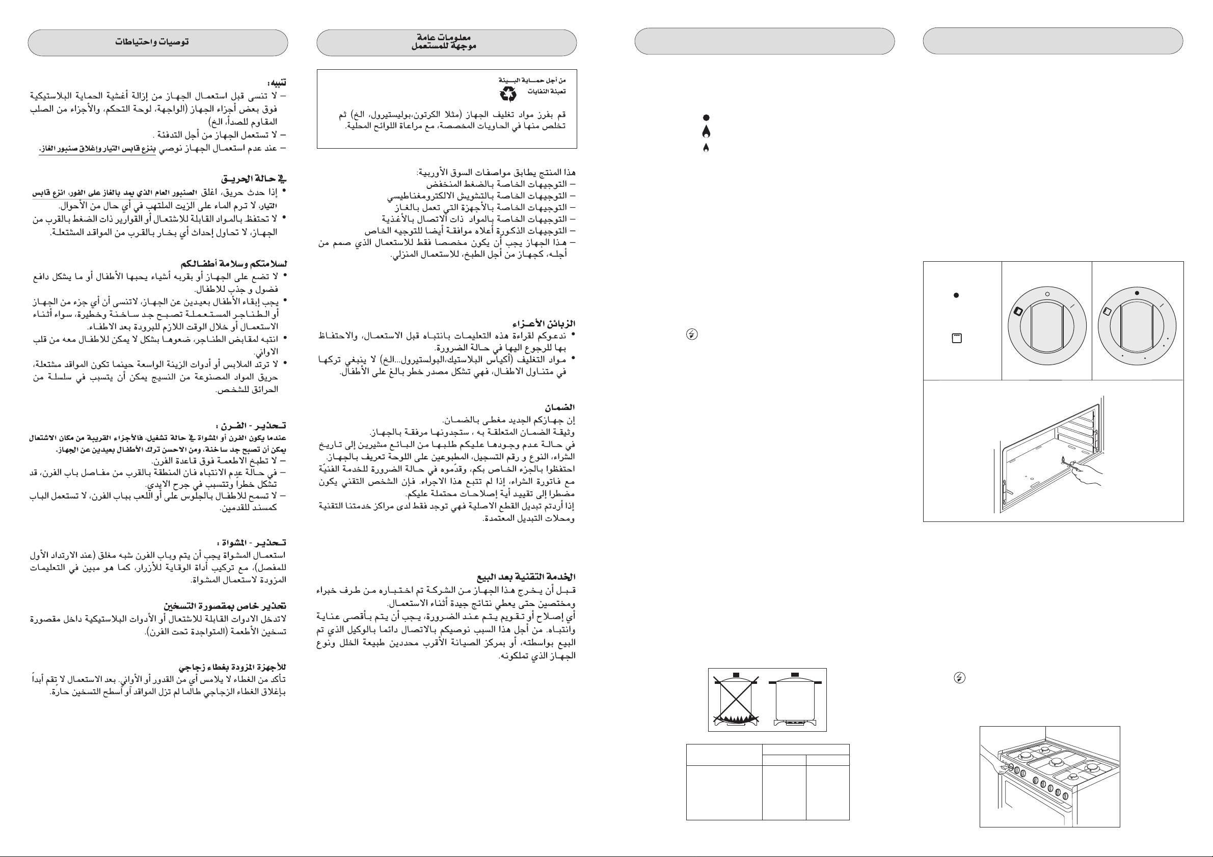
The following symbols are on the control panel ne xt to each knob:
- Black circle gas off
- Large flame maximum setting
- Small flame minimum setting
The minimum position is at the end of the anti-clockwise rotation
of the knob. All operation positions must be chosen between the
positions of max. and min., never choose them between max. and
off.
MANUAL IGNITION
To turn on a burner, approach a match to it, press the knob
corresponding to the selected burner and turn it anticlockwise to
the max position.
ELECTRIC IGNITION (optional)
To turn on a burner, press the knob corresponding to the selected
burner and turn it anticlockwise to the max position; simultaneously
pressing the electric ignition button on the control panel marked
with symbol .
In case there is no electric current, the burner can also be lighted
using a match.
USE OF THE GAS OVEN
The first time the oven is used, it may giv e off acrid smells, caused
by the first heating of isolating panels glue surrounding the oven
(it is necessary to heat up the oven at the maximum
temperature for about 30-40 minutes with closed door).
It is something normal, and in case it will occur, wait for the smok e
to stop before introducing the food into the oven.
The oven is fitted with: a rod shelf for cooking food contained in
oven dishes or placed directly on the rod shelf itself, a drip-tray
for cooking sweets, biscuits, pizzas, etc., or for collecting juices
and fats from food cooked directly on the rod shelf.
warnings: do not cook foods on the bottom in the base of
the oven.
GAS OVEN
MANUAL IGNITION OF OVEN BURNER
To ignite the oven burner, simply insert a match through the
opening (fig. 2) and then turn the tap to the maximum setting as
shown in figure 1.
Fig. 1
= CLOSED
Pos.1 : 140°C
Pos.8 : 250°C
= MINIMUM
= MAXIMUM
= GRILL
210
140
170
1
2
8
7
3
4
5
6
250
AUTOMATIC ELECTRIC IGNITION (optional)
To turn on a burner, press the knob corresponding to the selected
burner and turn it anticlockwise to the max position. Keeping the
knob pressed, the electric automatic ignition of the burner will be
started up.
In case there is no electric current, the burner can also be lighted
using a match.
APPLIANCES WITH SAFETY VALVE (optional)
Follow the same procedure described above to ignite the b urners.
In this case, however, once you have turned the knob to the open
setting, hold it pressed in for 10 seconds.
If for any reason the burner flame goes out, the safety valve
automatically shuts off the gas supply to the burner in question.
ENERGY SAVING TIPS
• The diameter of the pan bottom should be the same as that of
the burner. The b urner flame must never come out from the pans
diameter.
• Use flat-bottomed pans only.
• Whenever possible, keep a lid on the pan while cooking.
You will not need as much heat.
• Cook vegetables, potatoes, etc. with as little water as possible
to reduce cooking times.
Fig. 2
After making sure that the burner has lit properly , gently close the
oven door. To obtain the temperature required, simply turn the
pointer of the knob to the chosen number .
WARNING: Do not operate the ignition for more than 15
seconds. If the burner fails to ignite, lea ve the oven door open
for at least 1 minute before pressing the knob again.
Electric ignition of oven burner (optional)
The oven door must always be completely open, before the
burner ignition.
Turn the knob anti-clockwise to the maximum position, then press
button to ignite the burner.
In case there is no electric current, the burner can also be lighted
using a match. (fig 2).
BURNERS PANS
Ø min. Ø max
RAPIDE 180 mm 320 mm
SEMIRAPIDE 120 mm 220 mm
AUXILIARY 80 mm 180 mm
TRIPLE CROWN 220 mm 320 mm
ULTRARAPID 220 mm 320 mm
3 3
Fig. 3

GB
Automatic electric ignition (optional)
The oven door must always be completely open, before the
burner ignition
To ignite the burner, press the knob and turn it anti-clockwise to
the maximum position. Keep it pressed to start up the automatic
ignition of the burner.
In case there is no electric current, the burner can also be lighted
using a match.(fig 2).
Burner with safety device
For burners fitted with safety device, it it necessary to keep on
pressing the concerned knob for about 10 seconds after the ignition
(fig.3). In this way the safety valve will be started up. If for any
reason the burner flame goes out, repeat the procedure as
described above.
When you will be sure that the burner is on, close softly the oven
door.
To obtain the desired temperature, turn the knob index to the
selected number (tab.B).
Knob position Temperature °C
TAB. B
1 140 °C
2 150 °C
3 160 °C
4 170 °C
5 190 °C
6 210 °C
7 230 °C
8 250 °C
Wait at least 15 minutes before introducing the food, in order to
reach the desired temperature. Below you will find an indicative
cooking table (TAB.C).
TAB. C
FOOD TEMP . °C FOOD TEMP . °C
MEAT PASTRY
ROASTED PORK 185-210 FRUIT CAKE 220
ROASTED BEEF 250 MARGHERITA CAKE 190
ROASTED VEAL 220 BRIOCHES 175
ROASTED LAMB 220 SCONES 235
ROASTED HARE 230 RING-SHAPED CAKE 190
ROASTED RABBIT 235 PUFF-PASTE 200
ROASTED TURKEY 220 GRAPES CAKE 200
ROASTED GOOSE 235 STRUDEL 180
ROASTED DUCK 225 SAVOIA BISCUIT 290
ROASTED CHICKEN 235 APPLE FRITTER 200
ROAST-BEEF 200-225 PUDDING 200
FISH 200-225 TOAST 250
BREAD 230
to ignite the burner.
In case there is no electric current, the burner can also be lighted
using a match.
Automatic electric ignition (optional)
The oven door must always be completely open, before the
burner ignition.
To ignite the burner, press the knob and turn it clockwise to the
grill position . Keep it pressed to start up the automatic ignition
of the burner.
In case there is no electric current, the burner can also be lighted
using a match (fig.4).
WARNING: Do not operate the ignition for more than 15
seconds. If the burner fails to ignite, leave the oven door
open for at least 1 minute before pressing the knob again.
Burner with safety device
Repeat the above mentioned procedure, and press the ov en knob
at the same time. When the burner is on, keep the knob pressed
for about 10 seconds (fig.3). In this way the safety valve will be
started up. If f or an y reason the b urner flame goes out, repeat the
procedure as described above..
Heat the oven 5 minutes before introducing the food.
NOTE :
In some models the grill knob is separated from the thermostat
knob.(fig A).
WARNING:
Do not use the grill burner and the oven burner at one and
the same time, other than for the exclusive purpose of
preheating the oven (max 10/20 minutes)
140
250
Fig. A
170
210
210
140
170
1
2
8
7
3
4
5
6
250
WARNINGS: To turn the oven light on, press switch .
USE OF THE GAS GRILL
(ACCORDING TO THE MODELS)
Manual ignition of the grill
Open the oven door , then turn the ov en knob to the right and place
it on the grill position .
Bring a light match near the holes of the burner placed on the
oven upper part (fig.4).
Fig. 4
Electric ignition of grill burner (optional)
The oven door must always be completely open, before the
burner ignition.
Turn the knob clockwise to the grill position , then press button
NOTE:
The grill must be used with the door half-open (see fig5 A).
Fit the deflector S onto the centring pins N on the top of the oven
opening (fig.5 B ). Then gently close the oven door against the
deflector.
Use of the gas grill with the oven door closed
Some models are designed for the grill to be used with the oven
door completely closed.
In this case the deflector S shown in fig. 5B is not
supplied.
USE OF THE ELECTRIC GRILL
(ACCORDING TO THE MODELS)
In some other appliances the electric grill can be operated turning
the knob clockwise on position (fig C-D).
A warning light on the control panel will light up to inform you that
the grill is on.
Note: In some models the grill knob is separated from the
thermostat knob. (fig C)
WARNING:
Do not use the grill burner and the oven burner at one and
the same time, other than for the exclusive purpose of
preheating the oven (max 10/20 minutes)
ØØ
4 4

grill
working light
GB
Fig. 6
R L F
Fig. 6 A
M
H
250
210
170
140
1
2
3
4
5
Fig. C
480 mm
240 mm
8
Fig. D
SURFACE BAKING GRILL
(480x240)
7
second
level
6
NOTE:
The grill must be used with the door half-open (see fig5 A).
Fit the deflector S onto the centring pins N on the top of the oven
opening (fig.5 B ). Then gently close the oven door against the
deflector.
Use of the electric grill with the oven door closed
Some models are designed for the grill to be used with the oven
door completely closed.
In this case the deflector S shown in fig. 5B is not
supplied.
Fig. 5 A Fig. 5 B
N
P
Fig. 6 B
G
L
I
R
G
F
A
TURNSPIT single
For utilization of the turnspit follow the instructions described .
- Put the food in spit L (see fig. 7), pa ying attention to b loc k it within
the two forks F and to balance it, in order to avoid an y unnecessary
effort in motor R.
- Put the spit on support G, after having put its opposite end into
hole P of motor R.
- Place the drip-tray with a little water under the spit.
For some models, the turnspit must be used with the oven
door open; in this case, fit the deflector S onto the centring
pins N on the top of the oven opening (fig.5 B ).
- To remote the spit, operate in the opposite direction using knob
S and protecting glove in isolating wool (fig.7).
R
P
S
USE OF THE TURNSPIT
For the functions of the turnspit turning the knob on the position
(fig E) or on the symbol (fig C) when the thermostat is
separate or, in some models, press the marked button with the
symbol .
TURNSPIT multilpe
For utilization of the turnspit follow the instructions described.
- Thread the chicken or the cubes of meat for roasting on the
spit L , ensuring that it is gripped safely between the two forks
F and balancing it properly to avoid unnecessary strain on the
trasmission R (fig 6).
- Put the spit on the suppor t G, after having introduced its
opposite end in the socket P of the transmission R (fig 6)
- Put the suppor t G completely into the oven so that the bar I
goes into the socket H of the turnspit motor M (fig 6A).
- Place the drip-tray with some water under the turnspit, on the
lowest level.
- For some models, the turnspit must be used with the oven door
open; in this case, fit the deflector S onto the centring pins N
on the top of the oven opening (fig.5 B ).
- when removing the spit, wear oven mitts, pull out support G
and use the handgrip A operating in the contrary way (fig 6B).
F
L
S
Fig. 7
G
INSTRUCTIONS FOR USE OF CONTROL DEVICES
(ACCORDING TO THE MODELS)
MINUTES COUNTERS (Fig.8 )
Turn the knob clockwise to set the desired cooking time.
The minutes minder can be adjusted from 1 to 60 minutes.
A sound signal will inform you that the chosen time is up.
5
10
15
20
25
Fig. 8
55
50
45
40
35
30
PCI "Campanil"TR 259 Analogic
1
2
8
7
6
3
4
5
Fig. E
5 5
Setting the clock
Press the control knob and turn clockwise.
Alarm programme adjustement
Turn the knob clockwise without pressing it in. At the end of the
programmed time an alarm will sound. To cancel it, turn the knob
to the bell.

GB
XII
XI
X
IX
I
II
III
IV
VIII
VII
ELECTRONIC TIMER FOR COOKER (Fig. 9)
Functions
On
The display flashes.
Time setting
Press the left button.
Set the time with buttons “+” and “-”.
This function remains activated 7 seconds after the last +/operation.
Timer setting
This function is permanently activated and it will be immediately
set with +/- buttons.
During setting the units are 10 seconds.
During count down the timer takes priority on the display.
The units are seconds.
The maximum time is 99 minutes.
The relay contact (when av ailable) is closed during the count down
only.
Reset timer
Press “+” and “-” buttons together and release “+” button first.
Signal
The signal after time out will stay 7 minutes if it has not been reset
with the “+” button (one touch only).
VI
V
This appliance must be earthed by law. Before connecting
the appliance to the electrical supply, check that the earth
system in your house is working correctly.
Check that unit voltage and power, marked on the rating plate
applied on the appliance, are correct for the supply. It is necessary
that the feeding network is protected by a powerful switch able to
disconnect completely the network with a contacts separation of
at least 3 mm. Be sure that the earth wire green/yellow is not
interrupted by the switch.
Important: The wires in the mains lead are so coloured:
- green/yellow = earth " "
- blue = neutral “N”
- brown = live “L”
The wire coloured green/yellow must be connected to the terminal
in the plug which is marked with letter 'E' or by the earth symbol
or coloured green or green/yellow. The wire coloured blue m ust
be connected to the terminal which is marked with letter 'N' or
coloured black. The wire coloured brown must be connected to
the terminal which is marked with letter 'L' or coloured red. The
supply cable must not come into contact with any component the
temperature of which exceeds the ambient temperature by 50°C.
If a plug is used for connection, the plug to be connected to the
supply cable and the socket to which it is connected must be of
the same type (conforming to the standards). Easy access to the
plug or the switch is ensured once the appliance is installed. Ensure
that there is sufficient cable allowed for any subsequent removal
of the unit. If the plug is non-rewireable, pay attention to the
following points: the plug must never be cut by the supply cord.
There is shock hazard when this plug is inserted in a socket-outlet
elsewhere in the house. Never use the plug without the fuse cover
fitted. Ref erring to the pertinent spare parts, apply to the appliance's
supplier. The manufacturer declines all responsibility for any
damage to persons or things caused by failure to observe
the rules indicated above.
Applance type Supply single-phase 230 V~
Type of cable section
Aii gas Rubber H05 RR-F 3 x 0,75 mm
All gas + elett. grill Rubber H05 RR-F
3 x 2,5 mm
2
2
F
L
A
R
P
F
L
S
G
B
A
5
B
5
N
S
Signal frequency
When the display shows the time of da y, the signal frequency can
be selected by pressing the “-” button. Three different frequencies
are selectable.
Fig. 9
1 Time of the day
2 Timing and insertion
3 Signal timng and insertion
ELECTRICAL CONNECTION
Connection of the appliance to the power mains should be done
by a licensed electrician familiar with local safety regulations.
REPLACEMENT OF THE CABLE
In case the cable is damaged, replace it in accordance with the
following instructions:
- open the box of the supply board as described on the picture
below;
- unscrew screw “A” fixing the cable;
- replace the cable with one of the same lenght and in accordance
with the features described on the table; switch the appliance
off, and close the gas tap
- the ‘green-yellow” earth wire must be connected to the terminal
“ “ and it must be about 10 mm longer thean the live wires;
- the “blue” neutr al wire must be connected to the terminal marked
with letter “N”;
- the live wire must be connected to the terminal marked with letter
“L”.
L
N
A
15
10
20
5
25
55
50
45
40
35
30
E
R L F
P
B
M
G
I
A
H
R
G
6 6

GB
XII
VI
I
II
III
IV
V
Before cleaning the appliance, disconnect the gas general
tap and unplug the appliance or disconnect power at the
main circuit breaker of the electrical system.
Do not clean the appliance surfaces when still hot.
IMPORTANT
Periodically check the external gas connection hole and
replace it when it shows any sign of deterioration. Do not
attempt to repair the gas hose under any cincumstances.
ENAMELLED SURFACES
Clean with a damp sponge using soap and water.
Grease can be easily removed using hot water or a specific
cleansing agent for enamelled surfaces. Do not use abrasive
cleansers.
Do not leave any acid or alkaline substances (lemon juice , vinegar ,
salt, etc.) on the enamel.
Clean the parts in stainless steel with specific cleansers for
stainless steel surfaces.
These detergents must be applied using a soft cloth.
GRIDS AND BURNERS
To clean the work-top burners, remove them by pulling upwards
and soak them for about 10 minutes in hot water with a little
detergent. After having cleaned and washed them, wipe them
carefully.
Make sure that no burner hole is clogged.
Clean the burners once a week or more frequently if necessary.
MAKE SURE YOU HAVE ASSEMBLED THE BURNERS IN A
RIGHT WAY.
XI
X
IX
VIII
VII
N
CARE AND MAINTENANCE
INSTRUCTIONS DESTINED TO THE USER
OVERALL DIMENSIONS
1450/1500
910/960
895
WARNINGS
The technical data are indicated on the data nameplate placed
on the rear of the appliance.
The adjustment conditions are stated on the label applied on the
packaging and on the appliance.
Do not use the oven door handle to move the appliance, such as
to remove it from the packaging.
The appliance is in class 1 or class 2 subclass 1.
INSTALLATION
IMPORT ANT : The coating of the furniture must be able to withstand
high temperatures (min. 90°C).
If the appliance is to be installed near units, leave the minimum
gaps specified in the table below.
610
850/900
100
L
N
H05 RR-F
H05 RR-F
OVEN DOOR
For some models, the oven door can be disassembled in the
following way:
hinges A are provided, for this purpose, with two mov ab le jumpers
B; these, once hooked to the hinges slots C, when the door is
completely opened, block them. After that lift the door outward
carring out the two movements shown in the picture. To do that,
operate on the door sides next to the hinges. In order to reassemble the door, introduce the hinges in their relevant slots.
Before closing the door, do not forget to remove the movable
jumpers B.
Attention, in proximity of the oven door hinges , there is hurt danger.
B C
A
The cooker is fitted with 4 legs for an e ventual alignment in height
with the furniture. To assemble them, it is necessary to raise the
OVEN
Clean the enamelled parts with a damp sponge using soap and
water. Grease can be easily removed using hot water or a specific
cleansing agent for enamelled surfaces.
A
Do not use abrasive cleansers.
cooker and to screw the four legs into the suitable threadings
placed on the corners on the bottom of the appliance .
min.100 mm
min. 50 mm min. 50 mm
min. 20mm
min. 650 mm
min. 20mm
min. 400 mm
7 7

ROOMS VENTILATION
GAS APPLIANCES
This appliance is not connected to a device to vent the comb ustion
products. It must theref ore be installed and connected in conf ormity
with the installation standards in force.
Particular attention must be paid to the standards on ventilation
of the room.
VENTILATION OF ROOMS
Remember that this appliance can be installed and work in wellventilated rooms only, according to the standards in force, such
as to allow, with openings on the external walls or with special
ducts, a correct natural or forced v entilation ensuring permanently
and sufficiently both the entry of the air needed for correct
combustion and the removal of spent air.
In particular when there is only this gas appliance in the room,
there must be a hood over the appliance to ensure the natural and
direct removal of spent air, with a vertical straight duct of length
equal to at least twice the diameter and a minimum section of at
least 100 cm2.
For the indispensable entry of fresh air into the room there must
be a similar 100 cm2 opening directly to the outside, situated at
a height near floor level so that it is not blocked either inside or
outside the wall and so as not to cause disturbances to correct
burners combustion and to the regular removal of spent air and
with a difference of height with respect to the outlet opening of at
least 180 cm.
Remember that the quantity of air necessary for combustion must
never be less than 2m3/h for each kW of power (see total power
in kW on the appliance data plate).
In all other cases, i.e. when there are other gas appliances in the
same room, or when natural direct ventilation is not possible and
natural indirect or forced ventilation must be installed, contact a
qualified specialist who will install and make the ventilation system,
scrupulously observing the regulations contained in the standards
in force.
The openings must be so positioned that there are no draughts
of air which cannot be tolerated by the occupants.
Moreover to eliminate combustion products, it is forbidden to use
flues already used by other appliances.
GB
The appliance must be connected to the gas piping in a workmanlike
way and in conf ormity with the regulations in force which lay down
the installation of a safety valve at the end of the piping.
For butane and propane a pressure reducer conforming to the
standards in force may perform this task.
The seal gaskets must be in accordance with rules.
Once the gas appliance has been connected, check the connection
seal by means of soapy water.
The end of the attachment is threaded.
The possible connections are:
1/2”
- by rigid pipe in iron or copper
- by flexible tube in stainless steel with continuing wall, with
mechanical connection in accordance with rules. The tube must
be directly connected to the manifold elbow (see Fig.34).
- by the insertion of a rubber tube in accordance with rules.
This tube must be connected directly on the push-on connector,
concerning the gas used, and it must be blocked with a band.
In the last case, check the tube's printed date of expiry and
replace it before this date.
WARNINGS
Concerning rubber flexible tubes (max. length 1500 mm), we
remember you:
1 - to avoid the tube to be narrowed or crushed
2 - do not submit it to traction or torsion efforts
3 - to avoid contact with sharp edges, etc...
4 - to avoid contact with parts reaching temperatures over 70°C
the ambient temperature
5 - to ensure that they can be checked for all their length.
HOSE
ATTACHMENT
FOR LIQUID
GAS
F
F
HOSE
ATTACHMENT
FOR NATURAL
GAS
c
electrical fan
min. 180 cm.
min. 100cm2. min. 100cm2.
min. 180 cm.
min. 100cm2.
GAS CONNECTION
We recommend to check wether the appliance has been f oreseen
for the kind of gas distributed.
Fig. 10
If the connecting tube must be passed behind the appliance,
observe the regulations of the picture, making sure in the last case
that the tube is kept in support A.
INLET STOP
8 8
B C
A

GB
GAS ADJUSTMENT
If the appliance is foreseen to operate with a type of gas different
from the suitable supply gas, proceed as follows: change the
injectors, adjust the minimum flow of the burners, change the
push-on connector.
C
In order to change the work-top injectors, it is necessary to act as
¦
"
follows: remove the grids, remove burners and flame-spreaders
(see fig.A), change the injector (see fig.B) and replace it with
FIG.F
another one suitable for the new type of gas (see table D). Reassemble ev erything in the opposite direction, paying attention to
place the flame-spreader in the right way on the burner.
FIG.G
TAB. D GENERAL INJECTORS TABLE
Kind of gas mbar Nozzle Burners Power Watt Consum.
A B
NATURAL 20 0.97 Semi rapide 1750 480 167 l/h
To change the oven injector, it is necessary to act as follows: open
the oven door, remove the lower side of the oven (see fig.C),
unscrew screw C and disassemble the oven burner (see fig.D).
1.45 UltraRapide 3600 1500 343 l/h
1.20 Fish 2900 1500 277 l/h
Change the injector (see fig.E) and replace it with another one
suitable for the new gas type (see table D).
Re-assemble ev erything in the opposite direction, paying attention
to place the burner in the right way on its rear slot.
F
F
G.P.L. 30 0.85 Rapide 3000 750 219 g/h
BUTANE 28 0.65 Semi rapide 1750 480 128 g/h
PROPANE 37 0.50 Auxiliary 1000 330 73 g/h
NATURAL 20 1.25 Grill 2800 253 l/h
G.P.L. 30 0.75 Grill 2800 204 g/h
BUTANE 28
PROPANE 37
MINIMUM FLOW ADJUSTMENT FOR WORK-TOP TAPS
FIG.C
In order to adjust the minimum, act as follows: switch the burner
on, and turn the knob towards the minimum flow position .
Remove the knob from the tap , introduce a little scre wdriver in the
tap rod (fig. 11).
Attention: in taps with security valv e , the minimum adjusting scre w
“Z” is placed outside the rod tap (fig. 12).
C
N. Position-type max. min. max.
1.15 Rapide 3000 750 286 l/h
0.72 Auxiliary 1000 330 95 l/h
1.28 Triple crown 3300 1300 315 l/h
1.50 Oven 4300 389 l/h
1.45 Grill 3800 344 l/h
0.93 Triple crown 3300 1300 241 g/h
0.96 UltraRapide 3600 1500 262 g/h
0.85 Fish 2900 1500 211 g/h
1.00 Oven 4300 313 g/h
0.95 Grill 2800 277 g/h
with separated thermostat
Z
FIG.D
FIG.E
To change the grill injector, it is necessary to act as follows: open
the oven door, unscrew screw C and disassemble the grill burner
(see fig.F). Change the injector (see fig.G) and replace it with
another one suitable for the new gas type (see table D).
Re-assemble ev erything in the opposite direction, paying attention
to place the burner in the right way on its rear slot.
9 9
Fig. 11
Fig. 12
Unscrew the adjusting screw in order to increase the flow or scre w
it to decrease the flow.
The right adjustment is obtained when the flame has a length of
about 3 or 4 mm.
For butane/propane gas, the adjusting scre w must be tight screw ed.
Make sure that the flame does not go out passing quickly from
the max. flow to the minimum flow and viceversa .
Assemble the knob again.
MINIMUM FLOW ADJUSTMENT FOR OVEN THERMOSTAT
In order to adjust the minimum, act as follows: switch the burner
on turning the knob to the maximum position.
Remove the knob and unscrew of some turns the by-pass screw
(fig. H).
Assemble the knob and let the oven w arm up for 15 minutes; after
that turn the knob to the minimum position.

After having removed the knob once again, making sure that the
thermostat rod has not been moved, screw slightly the above
mentioned by-pass screw , to obtain a flame of 3 or 4 mm of length.
For butane/propane gas, the adjusting scre w must be tight scre wed.
Make sure that the flame does not extinguish passing quickly from
the maximum flow to the minimum flow, and closing and opening
the oven door (the oven door must be closed softly).
Attention: f or taps with saf ety device, the minimum adjusting screw
“T” is on the outside of the tap rod (fig. I ).
T
GB
DISASSEMBLE OF WORK-TOP
In case it is necessary to repair or replace the inside components,
act as follows:remove the glass lid from its position slipping off it
upwards.
Remove the grids, remove burners and flame-spreaders (see
fig. 13), unscrew the visible screws “V” placed on the work-top
(see fig. 14). Disassemble the work-top by unscrewing the 4 rear
screws “A” (see fig. 15 ).
A B
V
Fig. H
Fig. I
REGULATION AIR ADJUSTER
REGULATION OF AIR ADJUSTER (oven burner )
To do this,
- Unscrews the screw (A ) in order to rotate the metal ring at the
end of the burner (fig L ).
In this way, entrace of the air increases or descreases, obtaining
a correct flame.
Be sure that the flame does not lift or light back or present a
yellow colouration .
REGULATION OF AIR ADJUSTER (grill burner )
To do this,
- Unscrews the screw (A ) in order to slip it forwards or backwards
(fig M).
In this way, entrace of the air increases or descreases, obtaining
a correct flame.
Be sure that the flame does not lift or light back or present a
yellow colouration .
A
Fig. 13
Fig. 15
Fig. 14
A
- To disassemble the control panel, unscrew the 4 internal screws
(B) fixing the control panel to the oven face ( fig 16 ).
Fig. 16
B
GREASING OF TAPS
WARNING:This operation m ust be carried out b y skilled staff.
If a tap becomes hard to be turned, grease it using a specific
grease withstanding high temperatures. Act as follows: switch the
appliance off, and close the gas tap open the work-top and
disassemble also the control panel as described on the previous
paragraph. Unscrew the two fixing screws from the burner body
(see picture) and remove the cone.
C
A
Fig. L Fig. M
APPLIANCE MAINTENANCE
WARNINGS
Isolate the cooker from the electricity supply before attempting to
replace the oven lamp.
The oven lamp used is of a special type withstanding high
temperatures. To replace it, act as follows: disassemble the
protecting glass (A) and replace the burnt lamp with one of the
same type. Reassemble the protecting glass.
E 14
25 W - 230 V~
T300°C
A
Clean the cone and its slot by means of a cloth soaked with diluent.
Z
Slightly grease the cone with the relevant g rease, put it in its slot,
and turn it some times. Remove the cone again, remove the
exceeding grease making sure the gas entries are not obstructed
by grease residuals. Assemble everything carefully in the opposite
direction check the connection seal by means of soapy water.
TAPS REPLACEMENT
Act as follows: switch the appliance off, and close the general tap
open the work-top and disassemble also the control panel as
described on the previous paragraph. Unscrew screw nut D of the
gas tube supplying the burner. Unscrew screw V fixing the tap to
the bridle and remove it (see picture).
Note: Ev ery time the tap is replaced, it is necessary to replace the
seal gasket too check the connection seal by means of soapy
water (see picture).
D
10 10
15
V
7
C
 Loading...