

Page 1
BM115T92RB
02227_PL_LT_CRD
Instruction manual
Please read these instructions care ful ly and make sure you un der stand
them before using this ma chine.
Anleitungshandbuch
Bitte lesen Sie diese Anleitungen sorgfältig durch und vergewissern Sie sich,
daß Sie diese verstehen, bevor Sie die
Maschine in Betrieb nehmen.
Manuel d’instructions
Merci de lire trés attentivement le
manuel d'instructions. Assurez-vous
d'avoir tout compris avant d'utiliser ce
tracteur.
Manual de las instrucciones
Por favor lea cuidadosamente y comprenda estas intrucciones antes
de usar esta maquina.
Manuale di istruzioni
Prima di utilizzare la macchina leggete
queste istruzioni con attenzione ed accertatevi di averle comprese bene.
Instructieboekje
Lees deze instructies aandachtig en
zorg dat u ze begrijpt voordat u deze
machine gebruikt.
Page 2

1
2
3
4
5
6
Safety rules. Reglas de seguridad.
Sicherheitsvorschriften. Norme antinfortunistiche.
Règles de sécurité. Veiligheidsregels.
Assembly. Montaje.
Zusammenbau. Montaggio.
Montage. Montering.
Functional description. Descripción del funcionamiento.
Funktionsbeschreibung. Funzionamento.
Description du fonctionnement. Beschrijving van functies.
Before starting. Antes del arranque.
Maßnahmen vor dem Anlassen. Prima dell’avviamento.
Avant de démarrer. Maatregelen vóór het starten.
Driving. Conducción.
Betrieb. Guida.
Conduite. Rijden.
Maintenance, adjustment. Mantenimiento, ajuste.
Wartung (Instandhaltung), Einstellung. Manutenzione.
Entretien, réglages. Onderhoud, afstelling.
3
18
36
43
46
56
Troubleshooting. Búsqueda de averías.
7
8
Wij houden ons het recht voor om veranderingen aan te brengen zonder voorafgaande
Störungssuche. Ricerca guasti.
Recherche des pannes. Het localiseren van fouten.
Storage. Conservación.
Aufbewahrung. Rismessaggio.
Remisage. Stallen.
We reserve the right to make changes without prior notice.
Ånderungen ohne vorherige Mitteilung sind vorbehalten.
Nous nous réservons le droit d'apporter des modifi cations sans avis préalable.
Nos reservamos el derecho a introducir modifi caciones sin previo aviso.
Ci riserviamo il diritto di modifi che o cambiamenti senza preavviso.
mededeling.
76
79
2
Page 3

1. Safety Rules
Safe Operation Practices for Ride-On Mowers
IMPORTANT: THIS CUTTING MACHINE IS CAPABLE OF AMPUTATING HANDS AND FEET AND THROWING OBJECTS. FAILURE
TO OBSERVE THE FOLLOWING SAFETY INSTRUCTIONS COULD RESULT IN SERIOUS INJURY OR DEATH.
I. Training
• Read the instructions carefully. Be familiar with the con trols
and the proper use of the equipment.
• Never allow children or people unfamiliar with the ins truc tions to use the lawnmower. Local regulations may restrict
the age of the operator.
• Never mow while people, especially children, or pets are
nearby.
• Keep in mind that the operator or user is responsible for
accidents or hazards occurring to other people or their
property.
Do not carry passengers.
• All drivers should seek and obtain professional and prac ti cal instruction. Such instruction should em pha size:
- the need for care and concentration when work ing
with ride-on machines;
- control of a ride-on machine sliding on a slope will
not be regained by the application of the brake.
The main reasons for loss of control are:
a) insuffi cient wheel grip;
b) being driven too fast;
c) inadequate braking;
d) the type of machine is unsuitable for its task;
e) lack of awareness of the effect of ground
conditions,especially slopes;
f) incorrect hitching and load distribution.
II. Preparation
• While mowing, always wear substantial footwear and long
trousers. Do not operate the equipment when barefoot
or wearing open sandals.
• Thoroughly inspect the area where the equipment is to
be used and remove all objects which may be thrown by
the machine.
• WARNING - Petrol is highly fl ammable.
- Store fuel in containers specifi cally de signed for this
pur pose.
- Refuel outdoors only and do not smoke while re fu el ing.
- Add fuel before starting the engine. Never remove
the cap of the fuel tank or add petrol while the engine
is running or when the en gine is hot.
- If petrol is spilled, do not attempt to start the engine
but move the machine away from the area of spillage
and avoid cre at ing any source of ig ni tion until petrol
vapors have dis si pat ed.
- Replace all fuel tanks and container caps securely.
• Replace faulty silencers.
• Before using, always visually inspect to see that the
blades, blade bolts and cutter assembly are not worn or
damaged. Replace worn or damaged blades and bolts
in sets to preserve balance.
• On multi-bladed machines, take care as rotating one blade
can cause other blades to rotate.
III. Operation
• Do not operate the engine in a confi ned space where
dan ger ous carbon monoxide fumes can collect.
• Mow only in daylight or in good artifi cial light.
• Before attempting to start the engine, disengage all blade
attachment clutches and shift into neutral.
• Do not use on slopes of more than 10°.
• Remember there is no such thing as a “safe” slope. Travel
on grass slopes requires particular care. To guard against
overturning;
- do not stop or start suddenly when going up or down hill;
- engage clutch slowly, always keep machine in gear,
especially when traveling down hill;
- machine speeds should be kept low on slopes and
during tight turns;
- stay alert for humps and hollows and oth er hidden
haz ards;
- never mow across the face of the slope, unless the
lawnmower is designed for this pur pose.
• Use care when pulling loads or using heavy equipment.
- Use only approved drawbar hitch points.
- Limit loads to those you can safely control.
- Do not turn sharply. Use care when re vers ing.
- Use counterweight(s) or wheel weights when sug gest ed in the instruction hand book.
• Watch out for traffi c when crossing or near roadways.
• Stop the blades from rotating before crossing surfaces
other than grass.
• When using any attachments, never direct discharge of
material toward bystanders nor allow anyone near the
machine while in operation.
• Never operate the lawnmower with defective guards,
shields or without safety protective devices in place.
• Do not change the engine governor settings or overspeed
the engine. Operating the engine at excessive speed may
increase the hazard of personal injury.
• Before leaving the operator’s position:
- disengage the power take-off and lower the at tach ments;
- change into neutral and set the parking brake;
- stop the engine and remove the key.
• Disengage drive to attachments, stop the engine, and
dis con nect the spark plug wire(s) or remove the ignition
key
- before cleaning blockages or unclogging chute;
- before checking, cleaning or working on the lawnmower;
- after striking a foreign object. Inspect the lawnmower
for damage and make repairs before re start ing and
op er at ing the equip ment;
- if the machine starts to vibrate abnormally (check
im me di ate ly).
• Disengage drive to attachments when transporting or
not in use.
• Stop the engine and disengage drive to attachment
- before refueling;
- before removing the grass catcher;
- before making height adjustment unless ad just ment
can be made from the op er a tor’s position.
• Reduce the throttle setting during engine run-out and, if
the engine is provided with a shut-off valve, turn the fuel
off at the conclusion of mowing.
3
Page 4

IV. Maintenance and Storage
• Keep all nuts, bolts and screws tight to be sure the equip ment is in safe working condition.
• Never store the equipment with petrol in the tank inside
a building where fumes may reach an open fl ame or
spark.
• Allow the engine to cool before storing in any enclosure.
• To reduce the fi re hazard, keep the engine, silencer, battery compartment and petrol storage area free of grass,
leaves, or excessive grease.
• Check the grass catcher frequently for wear or de te ri o ra tion.
• Replace worn or damaged parts for safety.
• If the fuel tank has to be drained, this should be done
outdoors.
• On multi-bladed machines, take care as rotating one blade
can cause other blades to rotate.
• When machine is to be parked, stored or left unattended,
lower the cutting means unless a positive mechanical lock
is used.
WARNING: Always disconnect spark plug wire and
place wire where it cannot contact spark plug in
order to prevent ac ci den tal start ing when setting
up, trans port ing, ad just ing or making re pairs.
4
Page 5
- nadat u een ongewenst voorwerp heeft geraakt.
3
Inspecteer de maaimachine op schade en voer
reparaties uit voordat u de machine weer start en
gebruikt;
- als de machine abnormaal begint te trillen (onmiddellijk controleren).
- vor dem Entfernen von Verstopfungen aus dem Mähwerk oder dem Auswurf;
• Schakel de aandrijving naar de hulpstukken uit tijdens
transport of als ze niet worden gebruikt.
• Stop de motor en schakel de aandrijving naar het hulpstuk
uit,
- voordat u tankt;
- voordat u de opvangzak verwijdert;
- voordat u de hoogte verstelt tenzij de hoogte vanuit
de bestuurdersplaats kan worden ingesteld.
• Minder gas tijdens het uitlopen van de motor, en als de
motor met een afsluitklep is uitgerust, moet u de brandstoftoevoer aan het einde van het maaien afsluiten.
IV. ONDERHOUD EN OPSLAG
• Houd alle moeren, bouten en schroeven goed vastgedraaid zodat u er zeker van kunt zijn dat de machine in
een veilige bedrijfsstaat verkeert.
• Sla de machine nooit in een gebouw op, waar dampen een
open vlam of vonk kunnen bereiken, terwijl zich benzine
in de tank bevindt.
• Laat de motor afkoelen voordat u hem in een besloten
ruimte opbergt.
• Beperk brandgevaar: houd de motor, geluiddemper, accuruimte en benzine-opslagruimte vrij van gras, bladeren
of een overmaat aan smeervet.
• Controleer de opvangzak vaak op slijtage of verwering.
• Vervang versleten of beschadigde onderdelen om
veiligheidsredenen.
• Als de brandstoftank afgetapt moet worden, moet dit
buiten worden gedaan.
• Op machines met meerdere messen dient u eraan te
denken dat het draaien van één mes andere messen kan
doen draaien.
• Wanneer de machine moet worden geparkeerd, opgeslagen of alleen moet worden gelaten, moet de maai-inrichting
neergelaten worden tenzij een mechanische vergrendeling
wordt gebruikt.
WAARSCHUWING: Maak de bougiekabel altijd
los, plaats hem waar hij de bougie niet kan raken
teneinde onverhoeds starten te voorkomen tijdens
het opstellen, vervoeren, afstellen of uitvoeren van
reparaties.
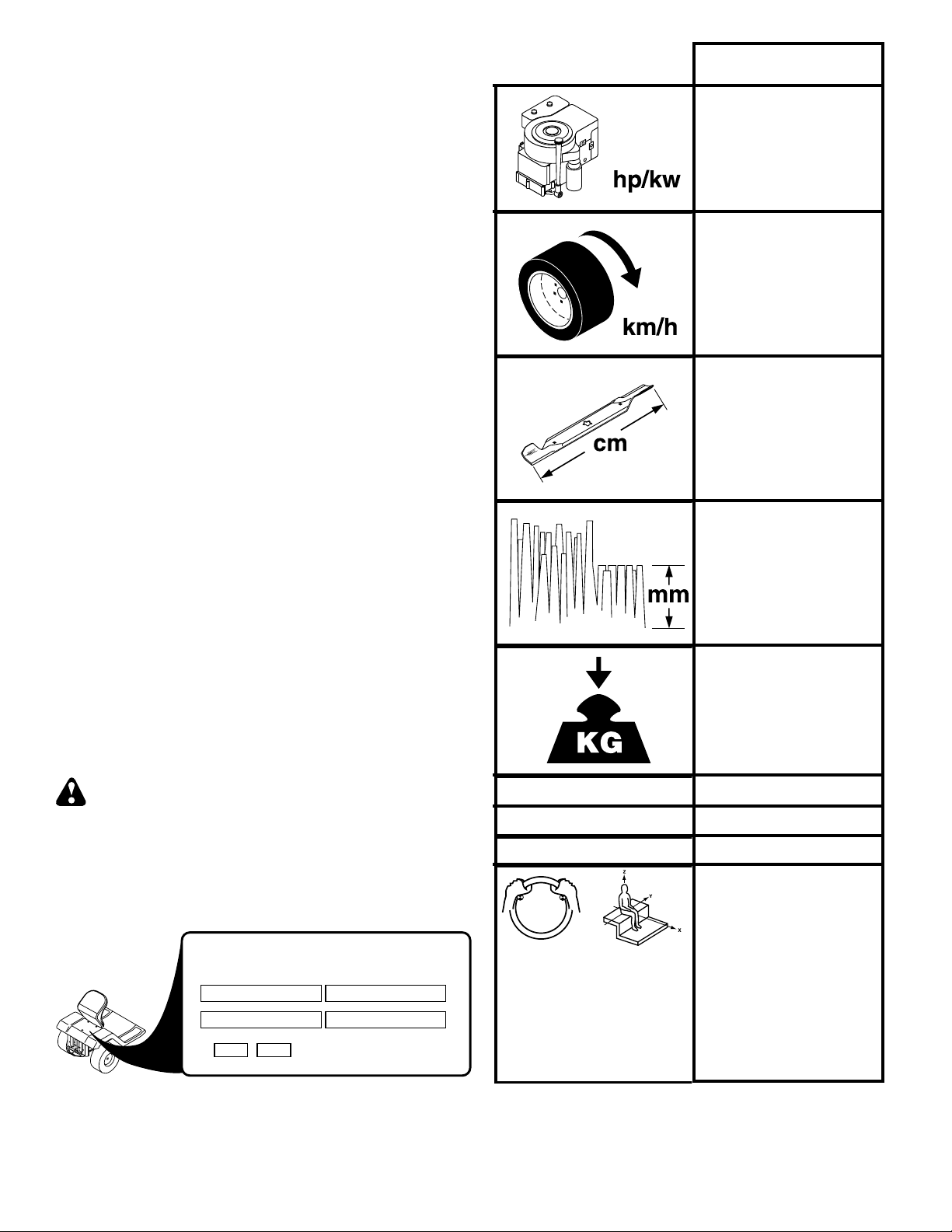
EN836:1997/A2
ISO 3744 98/37/EC
ISO 11094 2000/14/EC
BM115T92RB
11,5/8,6
0-6,7
92
38-102
235
LpA < 90 dBa
LwA < 100 dBa
MODEL/MODELE
MFG. ID NUMBER PRODUCT NO./PRODUIT NO.
KG RPM
MADE IN U.S.A.
HERGESTELLT IN DEN U.S.A.
FABRIQUE AUX E.U. 181080
2002
SERIAL/SERIE
02682
14
Vibration Lärmpegel
Vibration Vibratie
Vibración Vibrazioni
Vibrering Vibration
Vibrasjon Tärinä
m/s
2
0266
EN 1033
4
EN 1032
8
Page 6

These symbols may appear on your machine or in the literature supplied with the product. Learn and understand their meaning.
Diese Symbole fi nden Sie auf Ihrer Maschine oder in Unterlagen, die mit dem Produkt ausgehändigt wurden. Bitte machen Sie
sich mit deren Bedeutung vertraut.
Ces symboles peuvent fi gurer sur tracteur ou dans les publications fournies avec le produit. Apprenez à comprendre la signifi cation de ces symboles.
Estos símbolos pueden aparecer sobre su unidad o en la literatura proporcionada con el producto. Aprenda y comprenda sus
signifi cados.
Simboli utilizzati sull'apparato di taglio o nella documentazione fornita unitamente al prodotto. E' importante conoscerne bene il
signifi cato.
Deze symbolen kunnen op uw machine of in de bij het produkt geleverde documentatie aanwezig zijn. Lees en begrijp de betekenis.
REVERSE
RÜCKWÄRTSFAHRT
MARCHE ARRIÈRE
MARCHA ATRÁS
RETROMARCIA
ACHTERUIT-RIJDEN
ENGINE OFF
MOTOR AUS
MOTEUR ARRÊTÉ
MOTOR APAGADO
MOTORE SPENTO
MOTOR UIT
CLUTCH
KUPPLUNG
EMBRAYAGE
EMBRAGUE
FRIZIONE
KOPPELING
CLUTCH ENGAGED
ANBAUGERÄTE-KUPPLUNG
LAMES EMBRAYÉES
EMBRAGUE DEL ACCESORIO
FRIZIONE ACCESSORIE
KOPPELING HULPSTUK
NEUTRAL
LEERLAUF
POSITION NEUTRE
PUNTO NEUTRO
FOLLA
NEUTRAALSTAND
ENGINE ON
MOTOR LÄUFT
MOTEUR EN MARCHE
MOTOR ENCENDIDO
MOTORE ACCESO
MOTOR AAN
CHOKE
STARTKLAPPE
STARTER
ESTRANGULACIÓN
STARTER
CHOKE
ATTACHMENT
EINGEKUPPELT
ENGANCHADO
INNESTATA
INGESCHAKELD
HIGH
HOCH
HAUT
ALTO
AUMENTARE
HOOG
ENGINE START
ANLASSEN DES MOTORS
DÉMARRAGE DU MOTEUR
ARRANQUE DEL MOTOR
AVVIAMENTO DEL MOTORE
HET STARTEN VAN DE MOTOR
FUEL
KRAFTSTOFF
CARBURANT
COMBUSTIBLE
CARBURANTE
BRANDSTOF
CLUTCH DISENGAGED
ANBAUGERÄTE-KUPPLUNG
LAMES DÉBRAYÉES
EMBRAGUE DEL ACCESORIO
FRIZIONE ACCESSORI
KOPPELING HULPSTUK
LOW
NIEDRIG
BAS
BAJO
DIMINUIRE
LAAG
OIL PRESSURE
PRESSION D'HUILE
PRESIÓN DEL ACEITE
PRESSIONE DELL'OLIO
ATTACHMENT
AUSGEKUPPELT
DESENGANCHDO
DISINNESTATA
UITGESCHAKELD
FAST
SCHNELLFAHRT
VITESSE RAPIDE
MARCHA RÁPIDA
AVANZAMENTO VELOCE
VELOCE
P
PARKING BRAKE
FESTSTELLBREMSE
FREIN DE PARKING
FRENO DE ESTACIONAMIENTO
FRENO DI PARCHEGGIO
PARKEERREM
ÖLDRUCK
OLIEDRUK
CAUTION
VORSICHT
DANGER
PRECAUCIÓN
ATTENZIONE
OPGELET
BATTERY
BATTERIE
BATTERIE
BATERÍA
BATTERIA
ACCU
SLOW
LANGSAMFAHRT
VITESSE LENTE
MARCHA LENTA
AVANZAMENTO LENTO
LANGZAAM RIJDEN
UNLOCKED
ENTRIEGELT
DEVERROUILLÉ
ABIERTO
DISINNESTATO
GEDEBLOKKEERD
RÜCKWÄRTSFAHRT
MARCHE ARRIÈRE
MARCHA ATRÁS
RETROMARCIA
ACHTERUIT-RIJDEN
MOWER HEIGHT
MÄHWERKHÖHE
HAUTEUR DE COUPE
ALTURA DE LA SEGADORA
ALTEZZA APPARATO
FALCIANTE
MAAIHOOGTE
LIGHTS ON
LICHT AN
PHARES ALLUMÉS
LUCES ENCENDIDAS
LUCI ACCESE
LICHTEN AAN
PARKING BRAKE LOCKED
FESTSTELLBREMSE VERRIEGELT
FREIN DE PARKING VERROUILLÉ
FRENO DE ESTACIONAMIENTO
FRENO DI PARCHEGGIO INNESTATO
PARKEERREM GEBLOKKEERD
REVERSE
VORSICHT, HOCHGESCHLEUDERT
ATTENTION AUX PROJECTILES
CERRADO
BEWARE OF
THROWN OBJECTS
GEGENSTÄNDE
CUIDADO CON
OBJETOS LANZADOS
ATTENZIONE AGLI OGGETTI
LET OP WEGGESLINGERDE
VOORWERPEN
IGNITION
ZÜNDUNG
ALLUMAGE
IGNICIÓN
AVVIAMENTO
ONTSTEKING
FORWARD
VORWÄRTSGANG
MARCHE AVANT
MARCHA HACIA
DELANTE MARCIA
VOORUIT
SCAGLIATI
15
Page 7

These symbols may appear on your machine or in the literature supplied with the product. Learn and understand their meaning.
Diese Symbole fi nden Sie auf Ihrer Maschine oder in Unterlagen, die mit dem Produkt ausgehändigt wurden. Bitte machen Sie
sich mit deren Bedeutung vertraut.
Ces symboles peuvent se montrer sur votre machine ou dans les publications fournies avec le produit. Apprenez à comprendre la
signifi cation de ces symboles.
Estos símbolos pueden aparecer sobre su unidad o en la literatura proporcionada con el producto. Aprenda y comprenda sus
signifi cados.
Simboli utilizzati sull'apparato di taglio o nella documentazione fornita unitamente al prodotto. E' importante conoscerne bene il
signifi cato.
Deze symbolen kunnen op uw machine of in de bij het produkt geleverde documentatie aanwezig zijn. Lees en begrijp de betekenis.
+
+
_
_
90N
MAX
150N
MAX
HOT SURFACES
HEISSE OBERFLÄCHEN
SURFACES CHAUDES
SUPERFICIES MUY CALIENTES
SUPERFICIE ROVENTE
HETE OPPERVLAKKEN
DRAWBAR LOADING
ANHÄNGESCHIENENLAST
CHARGEMENT DE LA BARRE DE TRACTION
CARGA DE LA BARRA DE ENGANCHE
CARICO DI TRAZIONE DELLA BARRA
BELASTING OP TREKHAAK
BRAKE/CLUTCH PEDAL
BREMS / KUPPLUNGSPEDAL
PÉDALE DE FREIN / D’EMBRAYAGE
PEDAL DE FRENO / DE EMBRAGUE
PEDALE FRENO/FRIZIONE
REM / KOPPELINGSPEDAAL
SOUND POWER LEVEL
NIVEAU DE PUISSANCE ACCOUSTIQUE
GERÄUSCHPEGEL
NIVEL DE LA POTENCIA ACÚSTICA
LIVELLO DELLA POTENZA SONORA
GELUIDSNIVEAU
10
NO OPERATION
ON SLOPES MORE THAN 10
NICHT AUF ABHÄNGEN MIT
MEHR ALS 10 STEIGUNG BETREIBEN
NE PAS UTILISER SUR DES
PENTES DE PLUS DE 10
NO OPERE SOBRE PENDIENTES
DEMÁSDE10
NON USARE SU PENDII CON
UN'INCLINAZIONE DI OLTRE 10
NIET OP HELLINGEN VAN MEER DAN
SOLLEVAMENTO APPARATO FALCIANTE
10 GEBRUIKEN
MOWER LIFT
MÄHWERKHUB
RELEVAGE DE L'UNITÉ DE COUPE
LEVANTAMIENTO DE LA SEGADORA
MAAIHOOGTEREGELING
TENIR LES PASSANTS À DISTANCE
NONAZIONARE LA MACCHINA SENZA IL CESTO O SENZO IL DEFLETTORE DI SCARICO
KEEP BYSTANDERS AWAY
ZUSCHAUER FERNHALTEN
GUÁRDESE LEJOS DE GENTE
TENERE LONTANI I PASSANTI
OMSTANDERS UIT DE
BUURT HOUDEN
DANGER, KEEP HANDS AND FEET AWAY
GEFAHR, HÄNDE UND FÜSSE FERNHALTEN
DANGER, GARDEZ LES MAINS ET LES PIEDS AU LOIN
PELIGRO, MANTENGA LAS MANOS Y LOS PIES LEJOS
PERICOLO. TENERE LONTANI MANI PIEDI
GEVAAR, HANDEN EN VOETEN UIT DE BUURT HOUDEN
DO NOT OPERATE WITHOUT BAGGER OR DEFLECTOR
NICHT IN BETRIEB NEHMEN OHNE GRASFANGBOX ODER DEFLEKTOR
NE JAMAIS UTILISER SANS BAC OU DÉFLECTEUR
NO PONGA EN MARCHA SIN RECOGEDOR O DEFLECTOR
READ OWNERS MANUAL
BETRIEBSANLEITUNG LESEN
LIRE LE MANUEL
D'INSTRUCTIONS
LEA EL MANUAL DE
INSTRUCCIONES
LEGGERE IL MANUALE
DELL'OPERATORE
GEBRUIKERSHANDLEIDING
LEZEN
EUROPÄISCHE VERORDNUNG
FÜR MASCHINEN-SICHERHEIT
CONFORME AUX NORMES DE
DIRECTIVO DE MAQUINARIA
EUROPEO PARA LA SEGURIDAD
NORMATIVE ANTINFORTUNISTICHE
EUROPEE PER MACCHINARI
VEILIGHEIDSRICHTLIJN VOOR
ZONDER STORTGOOT OF AFWIJKENDE SPATDOEK NIET OPEREREN
EUROPEAN MACHINERY
DIRECTIVE FOR SAFETY
SÉCURITÉ EUROPÉENNES
EUROPESE MACHINES
FREE WHEEL
FREILAUF
ROUE LIBRE
RUEDA LIBRE
COMANDO DISINNESTO
VRIJWIEL
WARNING
WARNUNG
ATTENTION
ADVERTENCIA
PERICOLO
WAARSCHUWING
16
Page 8
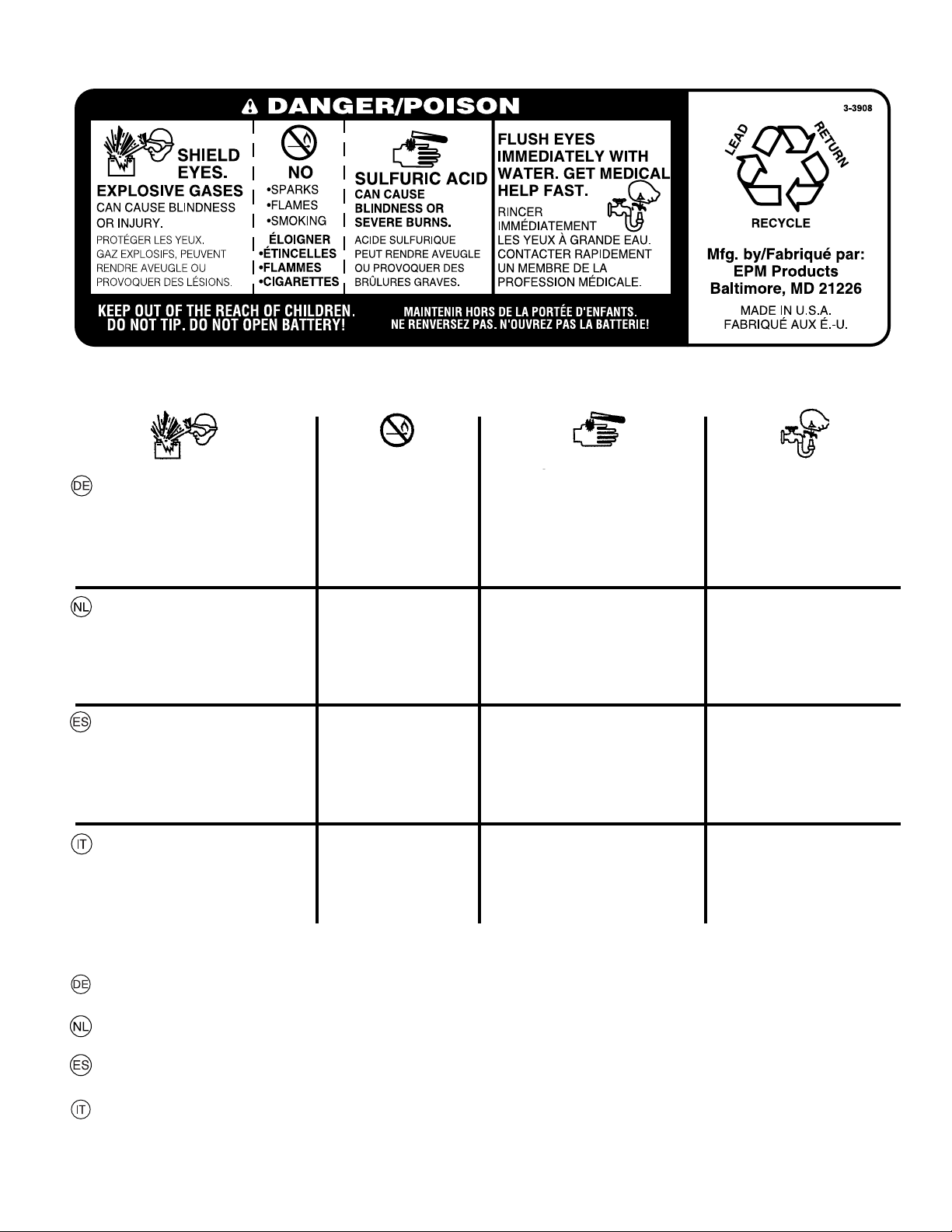
01738
GEFAHR
AUGEN SCHÜTZEN
EXPLOSIVE GASE
KÖNNEN ERBLINDUNG
UND KÖRPERVERLETZUNGEN VERURSACHEN.
GEVAAR
OGEN BESCHERMEN
EXPLOSIEVE GASSEN
KUNNEN BLINDHEID
OF LETSEL VEROORZAKEN.
PELIGRO
PROTEJE SUS OJOS
GASES EXPLOSIVOS
PUEDEN CAUSAR CEGUE-DAD O LESIONES.
PERICOLO
RIPARARE GLI OCCHI
VAPORI ESPLOSIVI
PUO’ PROVOCARE
CECITA’ O LESIONI
ZU VERMEIDEN:
• FUNKEN
• FEUER
• RAUCHEN
GEEN
• VONKEN
• VUUR
• ROKEN
NO
• CHISPAS
• LLAMAS
• FUMAR
DIVIETO
• SCINTILLE
• FIAMME
• SIGARETTE
SCHWEFELSÄURE
KANN ERBLINDUNG
ODER SCHWERE VERÄTZUNGEN VERURSACHEN.
ZWAVELZUUR
KAN BLINDHEID OF ERNSTIGE BRANDWONDEN
VER-OORZAKEN.
ÁCIDO SULFÚRICO
PUEDEN CAUSAR CEGUE-DAD O QUEMADURAS MUY GRAVES.
ACIDO SOLFORICO
PUO’ PROVOCARE LA
CECITA’ OD USTIONI
GRAVI.
AUGEN UNVERZÜGLICH MIT WASSER
AUSSPÜLEN. SOFORT
ÄRZTLICHE HILFE
AUFSUCHEN.
OGEN ONMIDDELLIJK
MET WATER SPOELEN.
SNEL MEDISCHE HULP
INROE-PEN.
LÍMPIESE LOS OJOS
CON UN CHORRO DE
AGUA.OBTENGA AYUDAMÉDICA RÁPIDAMENTE.
LAVAR E IMMEDIATAMENTE GLI OCCHI
CON ACQUA. SOTTOPORRE AL PIU’
PRES TO ALLE CURE
DEL MEDICO.
FÜR KINDER UNZUGÄNGLICH AUFBEWAHREN. NICHT KIPPEN. DIE BATTERIE NICHT ÖFFNEN!
UIT DE BUURT VAN KINDEREN HOUDEN. NIET KANTELEN. DE BATTERIJ NIET OPENMAKEN!
MANTENER FUERA DEL ALCANCE DE NIÑOS. NO LA INCLINE. ¡NO ABRA LA BATERÍA!
TENERE LONTANO DALLA PORTATA DEI BAMBINI. NON INCLINARE. NON APRIRE LA BATTERIA!
17
Page 9
2. Assembly. 2. Zusammenbau. 2. Montage. 2. Montaje
2. Montaggio. 2. Montering.
Before the tractor can be used certain parts must be as sem bled, which for transportation reasons are enclosed in
the packing.
Vor der Anwendung des Aufsitzmähers müssen gewisse
Teile eingebaut werden, die aus Transportgründen in der
Verpack-ung lose beigefügt sind.
Avant d'utiliser la tondeuse autoportée, certains éléments
livrés dans l'emballage doivent être montés.
1
Antes de poder utilizar el tractor, hay que montar algunas
piezas que, por razones de transporte, van empaquetadas
en el embalaje.
Prima di usare il trattore, montare alcune parti che per
ragioni di trasporto sono confezionate a parte.
Voordat de traktor gebruikt kan worden, moeten sommige
onderdelen worden gemonteerd, die vanwege het trans port
apart verpakt zijn in de emballage.
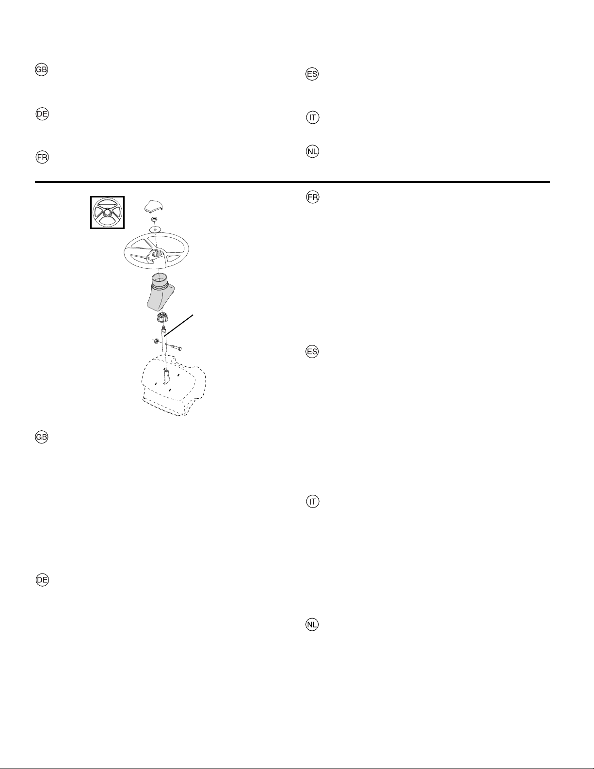
VOLANT DE DIRECTION
• Monter la rallonge de l'arbre de direction (1) en alignant
bien les trous. Bien serrer la vis et l'écrou.
• Positionner le carénage sur la colonne de direction.
S'assurer que les ergots du carénage sont bien placés
dans les trous correspondants du tableau de bord.
• Retirer l'adaptateur cranté du volant et le glisser sur
l'arbre de direction. Vérifi er que les roues avant sont
bien alignées selon l'axe d'avancement et positionner
le volant sur l'adaptateur. La traverse du volant doit être
perpendiculaire à l'axe d'avancement.
• Mettre en place la grande rondelle plate, la rondelle frein
et la vis ou l'écrou hexagonal(e). Serrer fortement.
• Encliqueter l'enjoliveur de volant dans le centre du volant.
1. RALLONGE DE L'ARBRE DE DIRECTION
02597
STEERING WHEEL
• Mount extension shaft (1). Tighten securely.
• Mount the main shaft cover. Make sure that the guide
tabs in the cover fi t the cover in respective holes.
• Remove steering wheel adapter from steering wheel and
slide adapter onto steering shaft . Check that the front
wheels are aligned forward and place the wheel on the
hub.
• Assemble large fl at washer and 1/2 hex nut. Tighten
securely.
• Snap insert into center of steering wheel.
1. EX TEN SION SHAFT
LENKRAD
• DieVerlängerungswelle (1). Gut festziehen.
• Lenkwellengehäuse einbauen. Dafür sorgen, daß die Führungsbolzen in die jeweils dafür vorgesehenen Bohrungen
ein- greifen.
• Nehmen Sie den Lenkradadapter vom Lenkrad ab und
schieben Sie diesen auf die Lenksäulenverlängerung
auf. Prüfen, daß die Vorderräder gerade stehen, und
das Lenkrad auf der Nabe anbringen.
• Die große Unterlegscheibe und die 1/2 kontermutter.
Sicher festziehen.
• Den Einsatz in die Mitte des Lenkrades eindrücken.
1. VERLÄNGERUNGSWELLE
VOLANTE DE DIRECCIÓN
• Introduzca el eje de extensión (1). Apriete en forma segura.
• Montar la cubier ta del eje del volant. Assegurarse de que
las espigas de guía de la cubierta encajan en los orifi cios
respectivos.
• Remueva el adaptador del volante y deslice el adaptador
sobre la extensión del eje de dirección. Controlar que
las ruedas delanteras están dirigidas hacia adelante y
poner el volante en el cubo.
• Monte una arandela plana grande una terercas de 1/2 y
apriete en forma segura.
• Presione la pieza inserta adentro del centro del volante
de dirección.
1. EJE DE EXTENCIÓN
VOLANTE
• Montare l'albero di estensione (1). Stringere saldamente.
• Montare il coperchio del piantone. Controllare che tutti i
pemi di guida entrino nei rispettivi alloggi.
• Rimuovere l’adattatore del volante dal volante e scorrerlo
sull’estensione dell’albero dello sterzo. Controllare che le ruote
anteriori siano ben dritte montare il volante sul mozzo.
• Assembiare la rondella piatta grande e il dadi 1/2. Tringere
in maniera salda.
• Scattare l'inserto al centro del volante.
1. ALBERO DI ESTENSIONE
HET STUUR
• Monteer de verlengas (1) en deze stevig vast.
• Monteer de stuuraskap. Let erop dat de stuurtaps in de
kap in de respectievelijke gaten vallen.
• Haal de stuuradapter van het stuur af en schuif de adapter op
het verlengstuk van de stuuras. Controleer of de voorwielen
recht naar voren staan gericht en plaats het stuur op de naaf.
• Bevestig de grote platte sluitring en de 1/2 borgmoer.
Zet ze stevig vast.
• Klik het inzetstuk in het midden van het stuur.
1. VERLENGAS
18
Page 10
02466
2
1
02464
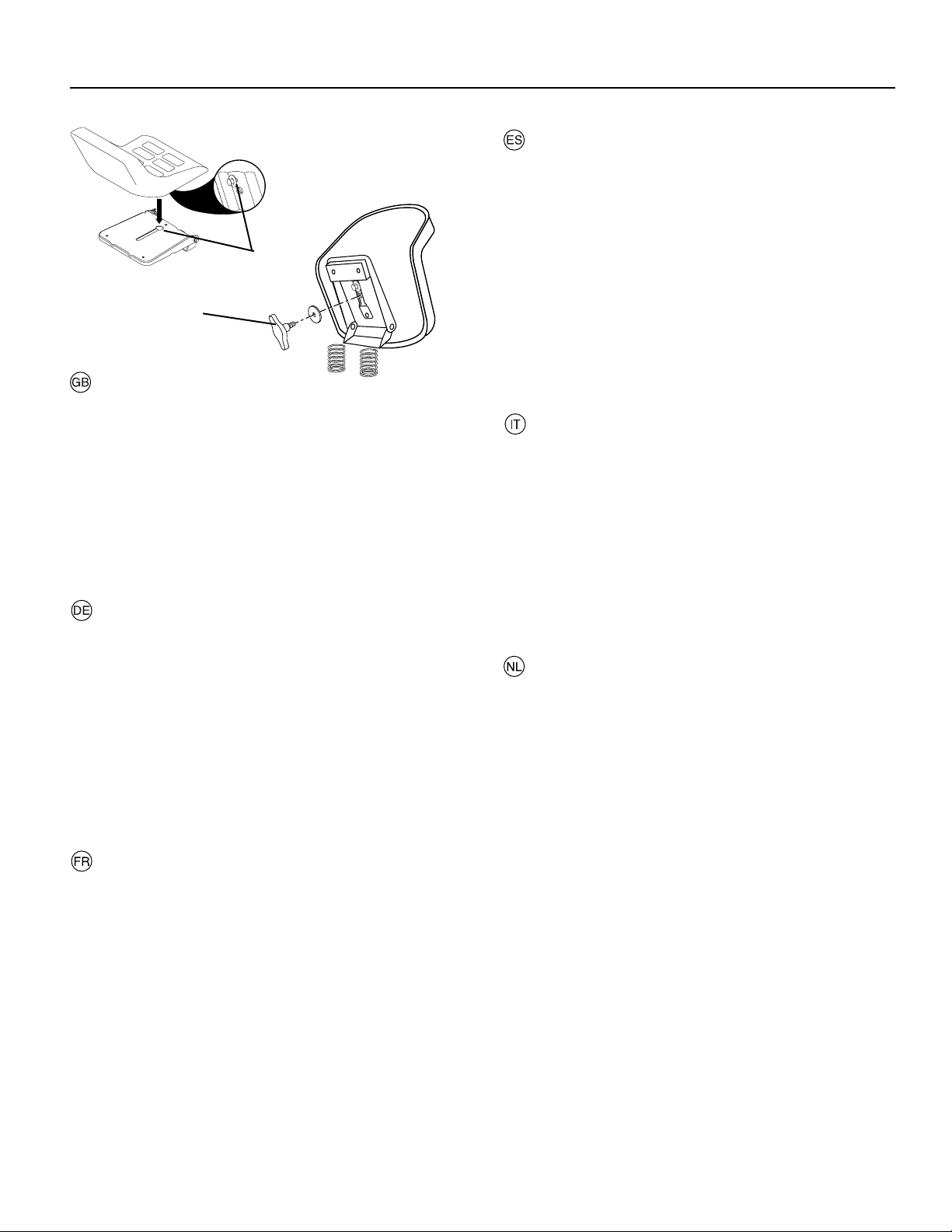
Seat
Remove the hardware securing seat to the cardboard pack ing
and set the hardware aside for assembly of seat to tractor.
Pivot seat upward and remove from cardboard packing. Remove the cardboard packing and discard.
Place seat on seat pan so head of shoulder bolt is positioned
over large slotted hole in pan (1).
Push down on seat to engage shoulder bolt in slot and pull
seat towards rear of tractor.
The seat is adjustable for individual setting in relation to the
clutch and brake ped al. Set the seat to the correct position
by moving it forwards or backwards. Tighten the adjustment
bolt securely (2).
Sitz
Entnehmen Sie die Teile, mit denen der Sitz an der Kartonage befestigt ist. Bewahren Sie diese Teile auf, da sie für die
Montage des Sitzes am Traktor noch benötigt werden.
Kippen Sie den Sitz nun nach oben, und nehmen Sie ihn aus
der Kartonage. Entfernen Sie die restlichen Verpackungsteile
und entsorgen Sie diese.
Der Sitz wird so auf die Sitzplatte plaziert, dass sich der
Hauptbolzen über dem Schlitz in der Platte befi ndet (1).
Sitz herunterdrücken, so dass der Bolzen in den Schlitz einrastet und dann den Sitz nach hinten ziehen.
Der Sitz ist persönlich im Verhältnis zum Kupplungs- bzw.
Bremspedal einstellbar. Den Sitz vor- oder zurückschieben,
bis die richtige Sitz-stellung erhalten wird. Die Einstellschraube
anziehen (2).
Siège
Retirer le bouton de réglage et la rondelle plate qui fi xent le
siège à l'emballage de carton, le conserver pour le montage
du siège sur le tracteur.
Basculer le siège vers le haut et le sortir de l'emballage de
carton. Se débarrasser ensuite de l'emballage.
Placer le siège sur son embase de façon que la tête de la vis
à épaulement se place dans le trou à l'extrémité de la large
fente de l'embase (1).
Pousser le siège vers le bas pour engager la vis à épaulement dans la fente puis repousser le siège vers l'arrière du
tracteur.
La position du siège seul, par rapport à la position de la pédale de frein et d'embrayage, est réglable. Rechercher une
position assise correcte en déplaçant le siège vers l'avant ou
vers l'arrière. Serrer ensuite à fond la vis de réglage (2).
2
Asiento
Remueva la manilla de ajuste y la arandela plana que aseguran el asiento al empaque de cartón y póngalos de lado
para poder utilizarlos durante la instalación del asiento sobre
el tractor.
Gire el asiento hacia arriba y remuevalo del embalaje de
cartón. Remueva y desechese del embalaje de cartón.
Colocar el asiento y en el asiento del recipiente de manera
que la cabeza del bulón de la espalda esté posicionada en
el agujero ancho ranurado en el recipiente.
Empujar en el asiento para enganchar el bulón de la espalda
en la ranura y empujar el asiento hacia la parte trasera del
tractor.
El asiento es ajustable individualmente en relación a los
pedales del embrague y de freno. Ajustar el asiento en la
posición correcta desplazándolo hacia adelante o atrás.
Apretar el tornillo de ajuste (2).
Sedile
Rimuovere i dispositivi di fi ssaggio che fi ssano il sedile
sull’imballaggio di cartone e mettere da parte i dispositivi di
fi ssaggio per assemblare il sedile sul trattore.
Muovere il sedile verso l’alto e rimuoverlo dall’imballaggio di
cartone. Rimuovere ed eliminare l’imballaggio di cartone.
Posizionare il sedile sulla relativa scocca in modo tale che il
bullone nella parte superiore dello spallamento si posizioni
sopra il foro grande posto sul fondo. (1).
Premere sul sedile per inserire il bullone dello spallamento
nella fessura e tirare il sedile verso il retro del trattore.
Il sedile è regolabile. Regolare il sedile fi no ad assumere la
posizione più comoda, spostandolo avanti o indietro. Stringere
la vite di regolanzione (2).
Zitting
Verwijder de bevestigingselementen waarmee de zitting aan
de kartonnen verpakking bevestigd is en zet deze bevestigingselementen opzij voor het monteren van de zitting op de
trekker.
Draai de zitting omhoog en haal hem uit de kartonnen verpakking. Verwijder de kartonnen verpakking en werp die weg.
Plaats de stoel op de zitpan zodat de kop van de borstbout
zich over het grote sleufgat in de pan bevindt (1).
Druk op de stoel totdat de borstbout in de sleuf past en trek
de stoel vervolgens naar de achterzijde van de tractor.
De zitting is verstelbaar voor de individuele instelling in
verhouding tot de koppelings- resp. rempedaal. Stel de zizting
in de juiste zitpositie door deze naar voor en naar achter te
schuiven. Haal de stelschroef aan.
19
Page 11
2
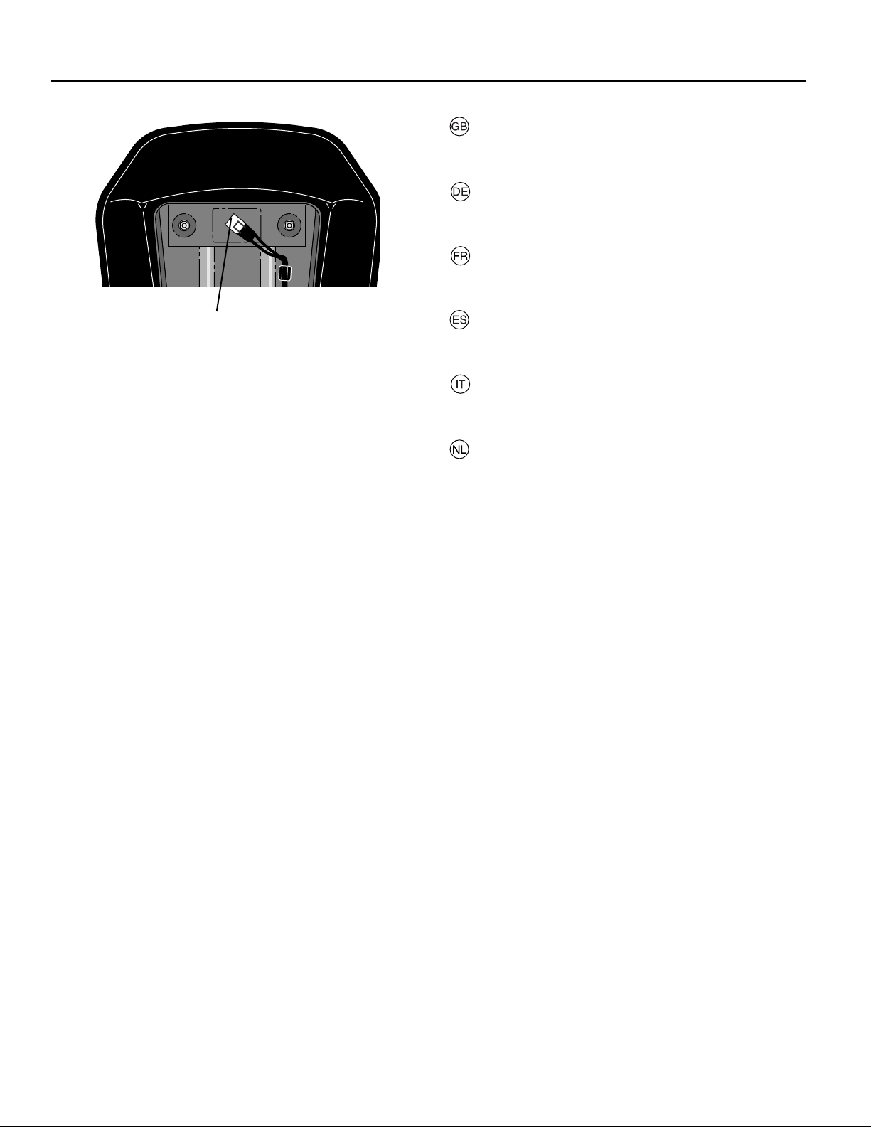
NOTE!
Check that the fl ex is correctly con nect ed to the safe ty switch
(3) on the seat hold er.
HINWEIS!
Prüfen, daß das Kabel richtig an dem Sicherheitsschalter (3)
auf dem Halter des Sitzes angeschlossen ist.
REMARQUE:
Vérifi er que le câble électrique est bien connecté sur le contacteur de sécurité (3) placé sous l'embase du siège.
3
NOTA!
Controlar que el cable está correctamente acoplado al interruptor de seguridad (3) en el soporte del asiento.
NOTA!
Controllare che il cavo sia ben collegato all’interruttore disicurezza (3) sul supporto del sedile.
N.B.!
Controleer of de snoer correct is aangesloten op deveiligheidsschakelaar (3), op de houder van de zitting.
20
Page 12
2
1. Battery Cover
2. Cable Positive (+)
3. Cable Negative (-)
4. Fender
5. Battery terminal
6. Battery
1. Batterieabdeckung
2. Positives Kabel (+)
3. Negatives Kabel (-)
4. Schutzblech
5. Batterieklemme
6. Batterie
1. Capotage de batterie
2. Câble (+)
3. Câble (-)
4. Carrosserie
5. Borne de la batterie
6. Batterie
1. Tapador del acumulador
2. Cable positivo (+)
3. Cable negativo (-)
4. Protección
5. Terminal de batería
6. Batería
1. Coperchio dellí accumulatore
2. Cavo elettrico positivo (+)
3. Cavo elettrico negativo (-)
4. Paraurti
5. Polo della batteria
6. Batteria
1. Accudeksel
2. Kabel positieve (+)
3. Kabel negatieve (-)
4. Stootwand
5. Accuklem
6. Accu
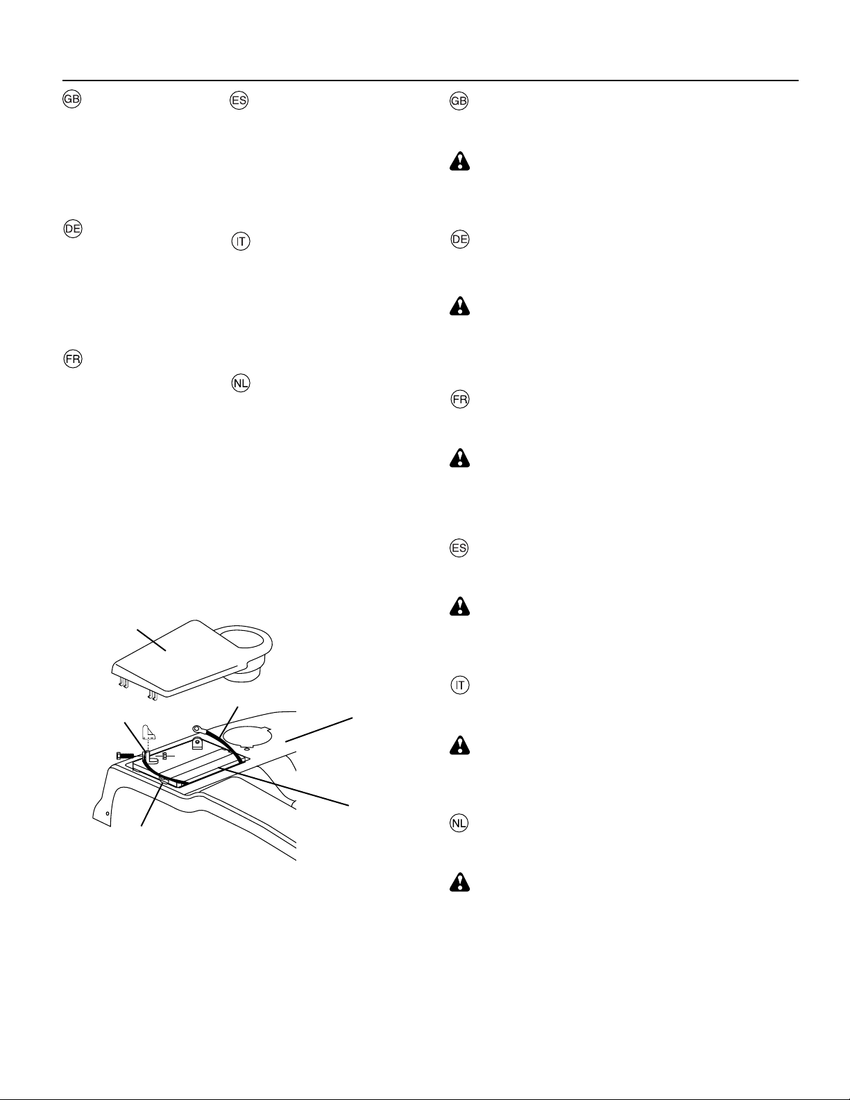
Install battery
NOTE: If battery is put into service after month and year
indicated on label, charge battery for minimum of one hour
at 6-10 amps.
WARNING: Before installing battery remove metal brace lets, wrist watch bands, rings, etc. from your person.
Touching these items to battery could result in burns.
• Remove Battery Cover
Einbau der Batterie
HINWEIS: Falls diese Batterie nach dem auf dem Aufkleber
angegebenen Datum (Monat und Jahr) in Betrieb genommen
wird, die Batterie mindestens eine Stunde lang mit 6 bis 10
Ampere aufl aden.
WARNUNG: Vor dem Einbau der Batterie Metallarmbänder,
Uhrarmbänder, Ringe und dgl. ablegen. Wenn diese
Gegenstäande mit der Batterie in Berührung kommen, könnte
dies Brandverletzungen verursachen.
• Entfernen Sie die Batterieabdeckung
Mise en place de la batterie
REMARQUE : Si la batterie est mise en service au-delà de
l'année et du mois indiqués sur l'étiquette, recharger la batterie, pendant une heure au moins, à 6-10 A .
ATTENTION : Avant de mettre en place la batterie, pren dre
la précaution de retirer gourmette, montre-bracelet, anneau, etc. Leur contact avec la batterie pouvant entraîner
des brûlures.
• Retirer le capotage de la batterie
Instalación de la batería
NOTA: Si utiliza la bateria después del mes y año indicado
sobre la etiqueta, cargue la batería por un mínimo de una
hora a 6-10 amps.
ADVERTENCIA: Antes de instalar la batería, quitese los
1
3
5
4
brazaletes metálicos, correas de reloj, sortijas, etc. Si estos
objetos tocan la bateria pueden producirse quemaduras.
• Quite el tapador del acumulador
Installazione della batteria
NOTA: Se questa batteria viene messa in uso dopo il mese
e l’anno indicati sull’etichetta, caricarla per almeno un’ora a
6-10 Ampère.
PERICOLO: Prima di installare la batteria eliminare anelli,
collane,braccialetti e altri oggetti di metallo dalla persona. Il
contatto del metallo con la batteria può causare incendi,
• Portare giuí il coperchio dellíaccumulatore.
6
2
02591
Accu installeren
N. B.: Als deze accu na de maand en het jaar, aangegeven
op het etiket, in bedrijf wordt genomen, laad de accu dan
minstens één uur op met 6-10 A.
WAARSCHUWING: Doe voor het intalleren van de accu alle
metalen voorwerpen: armbanden, ringen, horloges enz. Haf.
Anders kan het contact tussen deze voorwerpen en de accu
brandwonden veroorzaken.
• Verwyder het accudeksel.
21
Page 13
2
02591
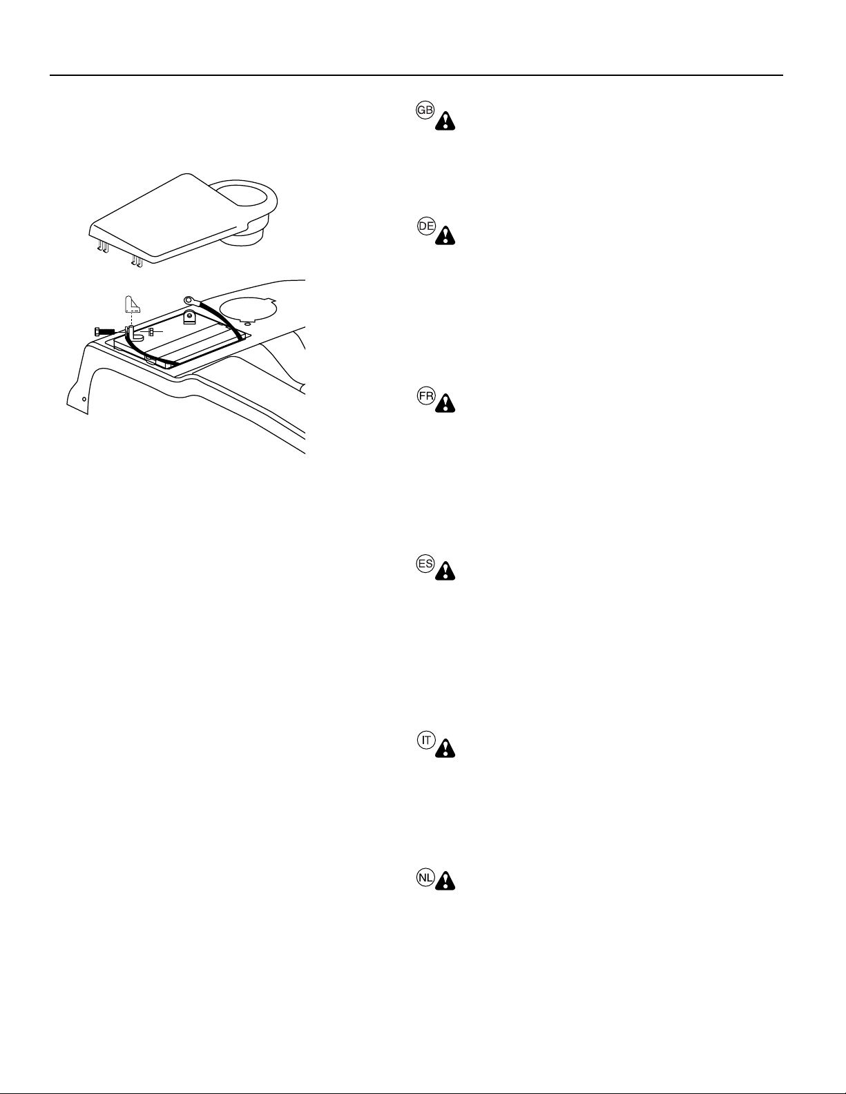
WARNING: Positive terminal must be con nect ed fi rst to
prevent sparks from ac ci den tal grounding.
Remove terminal caps and discard. Connect the red cable
to + and then the black earth ca ble to -. Screw tight the
cables. Grease the battery poles with vaseline to prevent
corrosion. Replace battery cover.
WARNUNG! Um einen Kurzschluß zu vermeiden, muß der
Pluspol zuerst angeschlossen werden.
Die Schutzkappen von den Anschlußklemmen entfernen und entsorgen. Die Batterie in Position neben den
Fahrersitz bringen. Die Batterieklemmen müssen nach
vorn zeigen. Zuerst das rote Kabel an „+“ und dann das
schwarze Kabel an„-“ anschließen. Die kabel fest
anschrauben. Batterieklemmen mit wasserfreiem Fett
(Vaseline) einfetten, um Korrosion zu verhindern.
Batterieabdeckung wieder montieren.
ATTENTION: La bor ne positive doit être connectée la première
afi n d'éviter les étincelles qui peuvent se produire à la suite
d'une mise à la masse accidentelle.
Retirer les capuchons de protection des bornes et les mettre
de côté. Placer la batterie dans son logement, les bornes du
côté extérieur. Raccorder en premier le câble rouge (+) à la
borne positive de la batterie puis le câble noir (-) à la borne
négative. Fixer les deux câbles à l'aide des vis et des écrous
fournis. Graisser les bornes de la batterie avec une graisse
résistante à l'humidité (vaseline) afi n d'éviter la corrosion.
Replacer le capotage de la batterie.
ADVERTENCIA: A fi n de evitar chispas por contacto
accidental a tierra hay que conectar primero el borne
positivo.
Remueva las tapas protectoras de los terminales y
póngalas de lado. Ponga la batería en su sitio debajo del
asiento. ‘Los bornes han de estar orientados hacia
adelante. Conecte primero el cable rojo al borne positivo
y después el negro de masa al borne negativo. Sujete los
cables. Lubrique los bornes con grasa que no contenga
agua (vaselina) a fi n de evitar la corrosión. Reponga el
tapador del acumulador.
PERICOLO: Il polo positivo deve essere collegato per
primo onde evitare scintille.
Togliere i cappucci protettivi dai poli e scartarli.Montare
la batteria nel vano sotto il sedile, con i poli in avanti.
Collegare il cavo rosso al polo positivo (+) e quello nero
negativo (-) alla terra. Ingrassare i poli con grasso privo
di acqua (vasellina) per evitare corrosione. Rimetter il
coperchiodellíaccumulatore.
WAARSCHUWING: De positieve klem moet eerst
aangesloten worden om vonken door per ongeluk aarden
te voorkomen.
Verwijder de beschermdoppen van de accupolen en gooi
ze weg. Zet de accu op zijn plaats onder de zitting. De
accupolen dienen naar voren te zijn gericht. Sluit eerst de
rode kabel aan op + en daarna de zwarte aard-kabel op
-. Schroef de kabels vast. Smeer de accupolen in met
watervrij vet (vaseline) om corrosie te voorkomen. Plaats
het accudeksel terug.
22
Page 14
02471
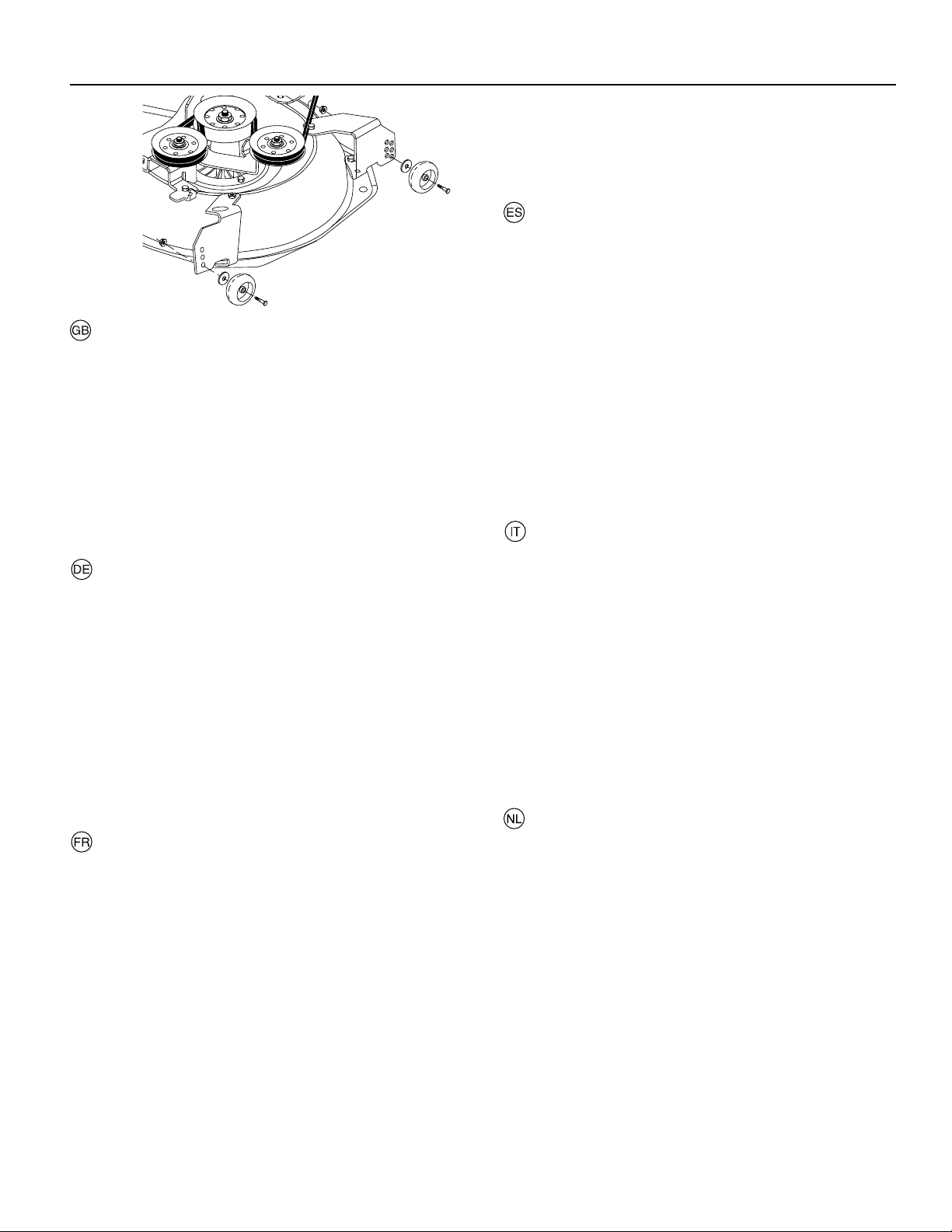
TO ADJUST GAUGE WHEELS
Gauge wheels are properly adjusted when they are slightly
off the ground when mower is at the desired cutting height in
operating position. Gauge wheels then keep the deck in proper
position to help prevent scalping in most terrain con di tions.
• Adjust gauge wheels with tractor on a fl at level surface.
• Adjust mower to desired cutting height.
• With mower in desired height of cut po si tion, gauge wheels
should be assembled so they are slightly off the ground.
In stall gauge wheel in appropr iate hole with shoulder bolt,
3/8 washer, and 3/8-16 locknut and tighten se cure ly.
• Repeat for opposite side installing gauge wheel in same
adjustment hole.
EINSTELLEN DER TASTRÄDER
Die Tasträder müssen sich in geringem Abstand vom
Boden befi nden, wenn das Mähwerk in Betriebsstellung
die gewünschte Schnitthöhe aufweist. Die Tasträder
halten dann das Mähwerk in der korrekten Stellung, um
in den meisten Terrains ein Abschuppen zu verhindern.
• Die Tasträder mit dem Traktor auf einer ebenen Fläche
einstellen.
• Den Mäher auf die gewünschte Schnitthöhe einstellen.
• Wenn sich das Mähwerk in der gewünschten Schnitthöhe befi ndet, sollten die Tasträder so zusammengebaut
werden, daß sie sich in geringem Abstand vom Boden
befi nden. Das erste Tastrad in die entsprechende Öffnung
einbauen.
• Auf der gegenüberliegenden Seite wiederholen und das
andere Tastrad in dieselbe Einstellöffnung einbauen.
REGLAGE DES ROULETTES DE JAUGE
Les roulettes de jauge sont correctement réglées
lorsqu'elles se trouvent légèrement au-dessus du sol
pendant la tonte, le carter de coupe étant à la hauteur
désirée pour la coupe.
• Régler les roulettes de jauge lorsque le tracteur se trouve
sur un terrain plat.
• Régler le carter de coupe à la hauteur de coupe désirée.
• Lorsque le carter de coupe est à la hauteur souhaitée, la
roulette de jauge doit être placée légèrement au dessus
du sol. Fixer la roulette de jauge dans le trou approprié
du support situé sur le carter de coupe à l'aide de la vis,
de la rondelle plate 3/8 et de l'écrou frein 3/8-16. Serrer
à fond.
• Répéter cette opération pour l'autre côté en plaçant la
seconde roulette dans le trou correspondant à celui utilisé
pour la première roulette de jauge.
2
PARA AJUSTAR LAS RUEDAS CALIBRADORAS
Las ruedas calibradoras están bien ajustadas cuando
se encuentran un poco a distancia del terreno al mismo
tiempo que la segadora esté a la altura de corte deseada. Entonces las ruedas calibradoras mantienen
el conjunto segador en posición para prevenir el corte
raspeo en casi todos los terrenos.
• Ajuste las ruedas calibradoras con el tractor en una
superfi cie nivelada plana.
• Ajuste la segadora a la altura de corte deseada con la
manilla de ajuste de altura.
• Con la segadora a la altura deseada para la posición de
corte, se tienen que montar las ruedas calibradoras de
modo que queden un poco sobre el suelo. Instale las
ruedas calibradoras en el agujero adecuado con el perno
con resalto, la arandela de 3/8, y la tuerca de seguridad
de 3/8-16 y apriételos en forma segura.
• Repita el procedimiento para el lado opuesto instalando
la rueda calibradora en el mismo agujero de ajuste.
REGOLAZIONE DEI RUOTINI ANTERIORI
La regolazione dei ruotini anteriori può essere eseguita
correttamente se sono leggermente sollevati da terra
quando il tosaerba si trova all’altezza di taglio desiderata
in posizione di esercizio. I ruotini anteriori mantengono
il piano di taglio nella corretta posizione aiutando ad
evitare l’asportazione del prato dalla maggior parte dei
terreni.
• Regolare i ruotini anteriori con il trattore posto su una
superfi cie piana e livellata.
• Regolare il tosaerba sulla desiderata altezza di taglio.
• Con il tosaerba nella desiderata altezza della posizione
di taglio, assemblare i ruotini anteriori in modo che siano
leggermente sollevati da terra. Installare il r uotino anteriore
nel foro appropriato.
• Ripetere sul lato opposto installando il ruotino anteriore
nello stesso foro di regolazione.
PEILWIELEN AFSTELLEN
De peilwielen zijn goed afgesteld wanneer ze een klein
beetje boven de grond zijn terwijl de maaier in de bedrijfsstand op de gewenste maaihoogte is. De peilwielen
houden het maaibord dan in de juiste stand om onder de
meeste terreinomstandigheden te helpen voorkomen dat
er te kort wordt gemaaid.
• Stel de peilwielen af met de tractor op vlakke, horizontale
grond.
• Stel de maaier op de gewenste maaihoogte af.
• Terwijl de maaier in de gewenste maaihoogtestand is,
dienen de peilwielen zodanig te worden gemonteerd dat
ze een klein beetje boven de grond zijn. Installeer het
peilwiel in het juiste gat.
• Herhaal dit aan de andere kant en installeer het peilwiel
in hetzelfde stelgat.
23
Page 15
2
02306
0
2
813
To install bagger com po nents to tractor
1
1. Dis charge Chute
2. 3/8 Nut
3. Flat Washer
2
1. Support Bracket
2. Clevis Pin 10 x 17mm
3. Retainer Spring
2
0
2277
4. Clevis Pin 10 x 50mm
5. 10,3mm (13/32") flat
washer
4
1
5
3
3
1
3
• Remove discharge chute from rear of tractor. Unhook the
two (2) straps and pull chute out and away from tractor.
• Remove the two (2) 3/8 nuts and fl at washers from the
bolts at the tractor back plate.
3
2
1
02330
1. 3/8 Lock nut
2. Flat Wash er
3. Support Tube
• Using the nuts and fl at washers removed from tractor
back plate, install the bagger support tube to the back
plate as shown. Tighten securely.
• Install the two upper support brack ets through the back
plate and to the chas sis, install the clevis pin 10x17mm
and secure with retainer spring.
• Assemble both support brackets to the outside of the
baggger support tube install the clevis pin 10x50mm and
secure with retainer spring.
2
1
1. Hook
2. Discharge Chute
3. Back plate slot
3
• Replace discharge chute into rear opening of tractor.
Secure the chute with the two hook straps.
NOTE: The strap hook must go through the discharge chute
only. Do not allow the hook to enter the slot in the tractor
back plate. This will allow the dis charge chute to fl oat with the
mower deck when moving on uneven terrain.
24
Page 16
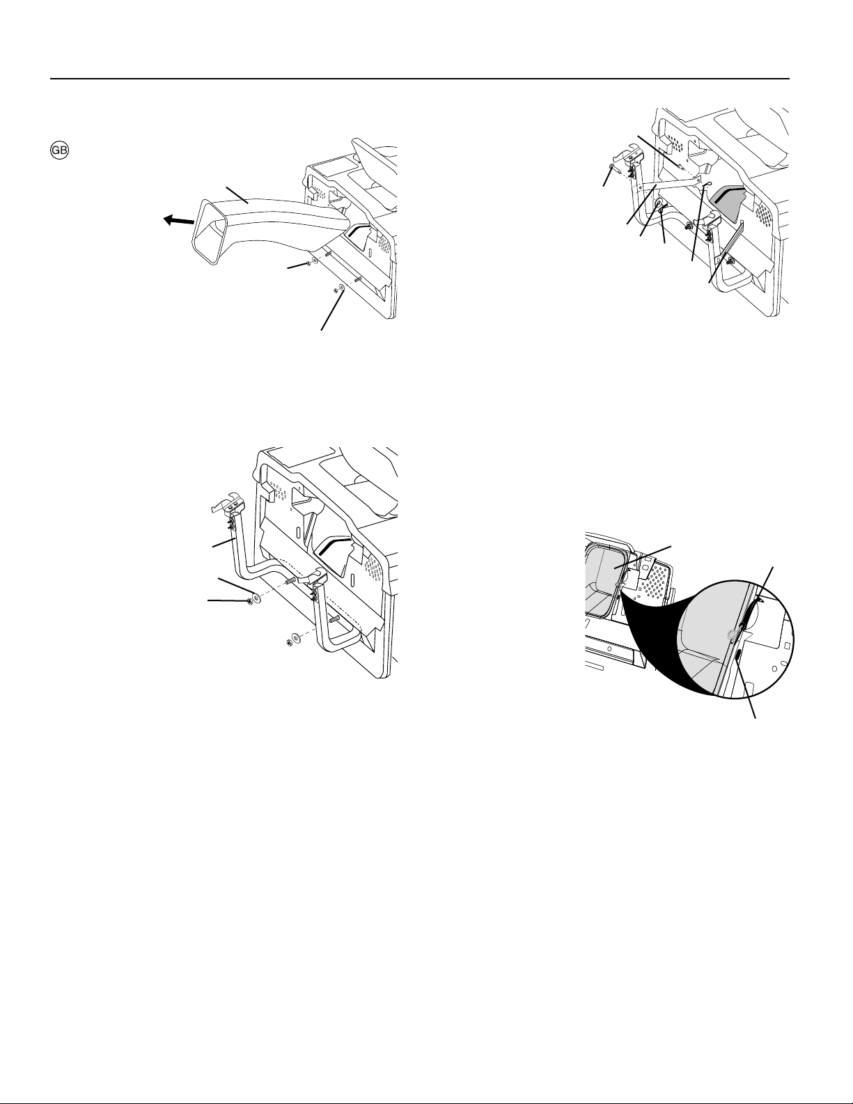
1
1. Front bagger tube
2. Lower bagger tube
3. 1/4 x 50,8mm Car riage
Bolts
4. 1/4 Lock nut
3
5
3
2
7
1. Front bagger tube
2. 1/4 x 50,8mm Car riage
Bolts
3. 1/4 Lock nut
4. Vinyl Binding
5. Dump handle tube
6. Clevis pin
7. Retainer spring
8. Cap
1
2
3
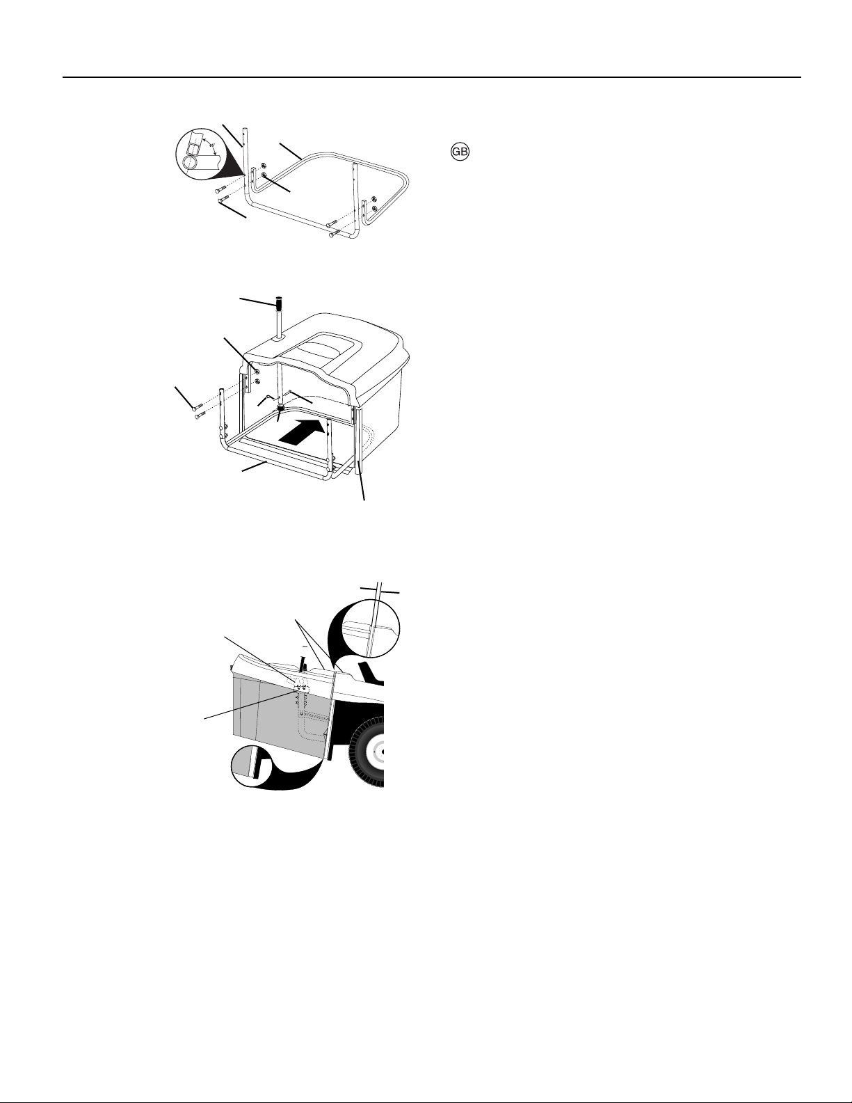
1. Top Surfaces Even
2. Horizontal Adjustment Brack et
3. Vertical Adjustment Brack et
2
4
0259
6
8
4
6MM (1/4") - 9MM (3/8")
1
02329
2
To Assemble Bagger
NOTE: For ease of assembly, you may wish to obtain the
assistance of another person when putting the bagger to geth er.
2
02593
• Holes in front bagger tube are at an angle. Place front
bagger tube against lower bagger tube and check for
proper hole alignment before assembling bolts.
• Assemble front and lower bagger tubes using four (4)
1/4 x 50,8mm carriage bolts and lock nuts supplied.
Tighten se cure ly.
• Slide front and lower bagger tube assembly into the bagger assemby.
• Assemble front and upper bagger tubes using four (4)
1/4 x 50,8mm carraige bolts and lock nuts supplied.
Tighten se cure ly.
• Slip all the vinyl bindings over the bagger tubes
• Slide the bagger dump handle through the hole in the
bagger top, install the clevis pin and secure with retainer
spring.
• Push cap over end of bagger dump handle.
NOTE: For future use, the clevis pin may be removed in order
to use the handle to clear the chute in the event it has become
clogged.
Bagger adjustment
For proper bag function and appearance, it may be nec es sary to adjust the bagger assembly. There should be 6mm
(1/4")-9mm (3/8") gap between the bagger top and fender and
the bagger top surface should be even with the top surface
of the fender. To adjust bagger position:
Horizontal adjustment
• Slightly loosen the nuts securing the bagger RH and LH
hor i zon tal adjustment brackets. Loosen only enough so
the brackets keep their position, but allow them to be
moved.
• Move the brackets the amount forward or back ward you
wish the bag assembly to move. Retighten the nuts securely.
Vertical adjustment
• Slightly loosen the nuts securing the vertical adjustment
brackets. Loosen only enough so the brackets keep their
position, but allow them to be moved.
• Move the brackets the amount up or down you wish the
bag assembly to move. Retighten the nuts securely.
• Reinstall the bagger as sem bly and check the bagger to
fender fi t. If necessary, repeat the procedure until proper
fi t is attained.
25
To convert to bagging, mulching or discharge
See "Sec tion 5" of this manual.
Page 17

3. Functional description. 3. Funktionsbeschreibung.
3. Description du fonctionnement.
3. Descripción del funcionamiento. 3. Funzionamento.
3. Beschrijving van functies
4
8
6
2
5
1
7
Positioning of controls
1. Throttle control
2. Brake and clutch pedal
3. Gear shift lever
4. Connection/disconnection of the cutting unit
5. Quick lifting/lowering of the cutting unit
6. Ignition lock
7. Parking Brake
8. Choke Control
3
02697
Anordnung der Bedienungseinrichtungen
1. Gashebel
2. Brems- und Kupplungspedal
3. Schalthebel
4. Ein- und Ausschalten des Mähaggregats
5. Schnelles Heben und Senken des Mähaggregats
6. Zündschloß
7. Feststellbremse
8. Kalstartregler
36
Page 18

3
02473
1. Throttle control
The throttle control regulates the engine revs and thus the
rotation speed of the blades.
= Full speed
= Idling speed
1. Gashebel
Mit dem Gashebel wird die Drehzahl des Motors und damit
die Drehgeschwindigkeit des Mähaggregats geregelt.
= Vollgas
= Leerlauf
1. Commande des gaz
La commande des gaz permet de faire varier le régime du
moteur et donc la vitesse de rotation des lames.
= Régime rapide
= Ralenti
01355
1. Acelerador
Se regula con él el régimen del motor y, por lo tanto, también
la velocidad de rotación de las cuchillas.
= Posición de plena aceleración.
= Posición de ralenti
1. Acceleratore
Questo comando aumenta o diminuisce il regime di giri
del motore e di consequenza la velocità di rotazione delle
lame.
= Pieno gas
= Minimo
1. Gashendel
Met de gasregelaar wordt het toerental van de motor geregeld
en daardoor ook de rotatiesnelheid van de messen.
= Volgas-positie
= Stationair-positie
38
Page 19

02473
02473
01358
2. Brake and clutch pedal
When the pedal is pushed down the brake is applied and the
motor is disengaged.
2. Brems- und Kupplungspedal
Beim Vorwärtsdrücken des Pedals wird das Fahrzeug abgebremst. Gleichzeitig wird der Motor ausgekuppelt und das
Fahrzeug rollt aus.
2. Pédale d'embrayage et de frein
En appuyant sur cette pédale, la transmission se débraye et
le frein entre en action simultanément.
3
2. Pedal de freno y de embrague
Al apretarlo se frena el vehículo y al mismo tiempo se desa
copla el motor deteniéndose la propulsión.
2. Pedale freno/frizione
Premendo il pedale il trattore si frena, il motore va in folle e
cessa la trazione.
2. Rem- en koppelingspedaal
Als de pedaal ingedrukt wordt, remt het voertuig. Tegelijkertijd
wordt de motor ontkoppeld en stopt de aandrijving.
3. Commande de la boîte de vitesses
La boîte de vitesses possèdent des vitesses avant, une position
neutre (point mort) et une marche arrière. Le pas sage des vitesses peut s'effectuer du point mort jusqu'à la vitesse maximale
sans s'arrêter sur les rapports intermédiaires. Toutefois il est
indispensable d'appuyer sur la pédale d'embrayage (et donc
de débrayer) lorsqu'on passe d'un rapport à un autre, quel qu'il
soit! Le démarrage du tracteur pouvant intervenir indépendamment de la po si tion du levier de vitesse, il est in dis pens able de
bien vérifi er que celui-ci est au point mort avant d'actionner la
clef de contact et de démarrer le moteur.
REMARQUE!
Toujours stopper le tracteur avant de passer de la marche arrière à un rapport de marche avant et inversement. Le passage
entre les différents rapports de marche avant ne doit jamais être
effectué pen dant le déplacement du tracteur. Ne jamais forcer
sur le levier lors du passage d'un rapport dans un autre.
00778
3. Gear shift lever
The gear box has positions forward, neutral and re verse.
Gear changing can take place from neutral to top gear without stopping in each gear position. Disengage the motor at
each gear position! Start can take place irrespective of the
gear lever position.
NOTE!
Stop the machine before changing from reverse to forward
gear, or the opposite. Gear changing between the forward
gears must not take place when the machine is in motion.
3. Schalthebel
Das Getriebe hat Vorwärtsgänge, Leerlauf und Rück-wärtsgang. Das Schalten kann von Leerlauf auf den schnell-sten
Gang ohne Aufenthalt bei den dazwischen liegenden Gängen
erfolgen. Dabei muß der Motor ausgekuppelt sein! Das Anfahren kann unabhängig von der Stellung des Schalthe-bels
erfolgen.
HINWEIS!
Der Aufsitzmäher vor dem Schalten aus dem Rückwär tsgang
in einen Vorwärtsgang, oder umgekehrt, anhalten. Das Umschalten zwischen den Vorwärtsgängen darf ebenfalls nur
bei stillstehendem Motor erfolgen. Niemals einen Gang mit
Gewalt schalten!
3. Palanca de cambios
La caja de cambios tiene posiciones hacia adelante, punto
neutro y marcha atrás. Los cambios pueden efectuarse desde
el punto neutro a la marcha más alta sin detenerse en cada
posición de cambio. Antes de cambiar de marcha, desembragar el motor. El arranque puede hacerse independientemente
de la posición de la palanca de cambios.
NOTA!
Pare la máquina antes de pasar de la marcha atrás a una marcha
adelante, o inversamente. El cambio entre las marchas hacia
adelante no debe hacerse si la máquina está en movimiento.
No utilice nunca la violencia para engranar una marcha.
3. Leva del cambio
Marce in avanti, folle e marcia indietro. Il cambio è sincro-nizzato e dal folle si può passare direttamente in sesta. Usare la
frizione prima di ogni cambio di marcia. L’avviamento avviene
indipendentemente dalla marcia inserita.
NOTA!
Prima di passare alla retromarcia o viceversa, fermare sempre la macchina. Il cambio marcia deve avvenire sempre a
macchina ferma. Cambiare senza violenza.
3. Versnellingshendel
De versnelingsbak heeft versnellingen vooruit, neutraal-stand
en achteruitstand. Er kan van de neutraalstand recht-streeks
tot de hoogste versnelling geschakeld worden, zonder oponthoud bij iedere versnelling. Gebruik de koppeling bij iedere
versnelling! Het starten kan plaatsvinden onafhankelijk van
de positie van de versnellingspook.
N.B.!
Laat de machine tot stilstand komen door van achteruit naar
vooruit of andersom te schakelen. Schakelen tussen de versnellingen vooruit mag niet gebeuren, wanneer de ma chine
in beweging is. Gebruik nooit geweld bij het schakelen.
39
Page 20

3
02473
02442
4. Connection/disconnection of the cutting unit
Move the lever forward to connect the drive to the cutting
unit, whereby the drive belt is tensioned and the blades begin
to rotate. If the lever is moved backwards the drive will be
disconnected and the rotation of the blades slowed down by
the action of the brake shoes on the pulley.
4. Ein- und Ausschalten des Mähaggregats
Den Hebel nach vorn führen, um den Antrieb des Mähers
ein-zukuppeln. Dabei wird der Antriebsriemen gespannt
und die Riemen beginnen sich zu drehen. Wenn der Hebel
zurückge-zogen wird, wird der Antrieb ausgekuppelt und
die Drehung der Klingen wird durch an die Riemenrollen
angesetzte Bremsklöt-ze gebremst.
4. Commande d'embrayage et de débrayage du
carter de coupe
Pousser le levier vers l'avant et le verrouiller pour embrayer
le carter de coupe. Les courroies d'entraînement seront alors
en tension et les lames commenceront à tourner. Ramener
le levier vers l'arrière pour débrayer le carter de coupe, les
lames seront alors freinées par le frottement des patins de
frein sur les poulies d'entraînement.
4. Acoplamiento y desacoplamiento del equipo
de corte
Lleve la palanca hacia adelante para acoplar la propulsión
del equipo de corte. Se tensarán entonces las correas propulsoras y empezarán a girar las cuchillas. Si la palanca se
lleva hacia atrás se desacopla la propulsión al mismo tiempo
que la rotación de las cuchillas es frenada por las zapatas de
freno que aprietan las ruedas de las correas.
4. Inserimento/disinserimento del dispositivo di
taglio.
Premere in avanti la leva per avviare il tagliaerba. La cinghia
entra in tensione e le lame cominciano a girare. Tirando indietro
la leva il tagliaerba viene disinserito e le lame vengono frenate
dalle ganasce dei freni che agiscono contro la puleggia.
4. Koppelen en onkoppeleen van de maaikast
Breng de hendel naar voren om de aandrijving van de maaikast te koppelen. Daarbij wordt de aandrijfriem gesteld en de
messen beginnen te roteren. Wordt de hendel naar achteren
gebracht, wordt tegelijkertijd de rotatie van de messen afgeremd, doordat de remblokken tegen de poelie lopen.
2
1
3
01350
5. Quick lifting/lowering of the cutting unit
Pull the lever backwards to quickly lift the cutting unit when
passing over irregularities in the lawn, etc. During trans por ta tion the cutting unit shall be in the highest position. Pull
the lever back until it locks. To lower the unit: Pull the lever
backwards (1). Push in the button (2) and then move the
lever forward (3).
5. Schnelles Heben und Senken des Mähaggregats
Den Hebel zurückziehen, um das Mähaggregat schnell bei der
Fahrt über z.B. unebene Stellen des Rasens anzuheben. Bei
Transportfahrt soll das Mähaggregat in der höchsten Stellung
stehen. Den Hebel zurückziehen, bis dieser gesperrt wird.
Senken des Aggregats: Hebel zurückziehen (1). Knopf (2)
drücken und danach den Hebel (3) nach vorn führen.
5. Relevage et abaissement du carter de coupe
Tirer sur le levier vers l'arrière (1) pour relever rapidement le
carter de coupe lors du passage sur une surface accidentée.
Pour le transport, le carter de coupe doit être dans sa position
la plus élevée (relevé au maximum). Pour cela, tirer le levier
vers l'arrière jusqu'à sa butée. Pour abaisser le carter de
coupe, tirer légèrement le levier vers l'arrière (1) puis enfoncer
le bouton poussoir (2) situé sur le dessus du levier, ramener
ensuite le levier vers l'avant (3) en maintenant la pression
sur le bouton poussoir.
5. Elevación/descenso rápidos del equipo de
corte
Tire de la palanca hacia atrás para levantar rápidamente el
equipo de corte al pasar sobre irregularidades del terreno,
etc. Al transportar la máquina, el equipo de corte ha de estar
en la posición más alta. Tire de la palanca hacia atrás hasta
que se bloquee. Para de scend er el equipo de corte:Tire de la
palanca hacia atrás (1). Apriete el botón (2) y lleve después
la palanca hacia adelante (3).
5. Sollevamento/abbassamento del tagliaerba
Per sollevare il tagliaerba quando sia necessario, tirare indietro
la leva. In caso di trasporto il tagliaerba deve essere sollevato.
Per abbassare il tagliaerba: Tirare indietro la leva(1). Premere
il pulsante (2) e portare poi la leva in avanti (3).
5. Snelle verhoging/verlaging van maaikast
Breng de hendel naar achteren om de maaikast snel te doen
verhogen bij het passeren van oneffenheden in het gazon. Bij
transport dient de maaikast in zijn hoogste stand te staan. Zet
de hendel achteruit, totdat deze vergrendeld is. Om de kast
te doen verlagen: Zet de hendel achteruit (1). Druk de knop
in (2) en breng daarna de hendel naar voren (3).
40
Page 21

01949
OFF ON START
3
6. Ignition Lock
There are three different positions for the ignition key:
OFF All electric current bro ken.
ON Electric current connected.
START Start motor connected.
WARNING!
Never leave the key in the ignition lock when leaving the
machine on its own.
6. Zündschloß
Der Zündschlüssel hat drei Rasten:
OFF Strom ausgeschaltet
ON Strom eingeschaltet
START Anlasser eingeschaltet
WARNUNG!
Niemals den Zündschlüssel im Zündschloß lassen, wenn die
Maschine unbeaufsichtigt verlassen wird.
6. Clé de contact et de démarrage
La clé de contact possède trois positions :
OFF Le circuit électrique est coupé (éteint)
ON Le circuit électrique est fermé (allumé)
START Le démarreur du moteur est alimenté (Dès
le démarrage du moteur , relâcher la clé qui
reviendra automatiquement sur la position
"ON")
ATTENTION!
Lorsque la machine doit rester sans sur veil lance, même pour
un court instant, toujours arrêter le moteur, mettre le levier
de commande de vitesse au point mort (Neutre) et retirer la
clé de contact.
6. Cerradura de encendido
La llave de encendido puede hallarse en tres posiciones
diferentes:
OFF Corriente eléctrica cortada
ON Corriente eléctrica conectada
START Motor de arranque acoplado
ADVERTENCIA!
Si abandona la máquina sin vigilancia, no deje nunca la llave
en la cerradura.
6. Chiave di accensione
La chiave ha tre posizioni:
OFF I circuiti elettrici sono interrotti
ON Attivazione del cisrcuito elettrico
START Inserimento del motorino di avviamento.
PERICOLO!
Prima di lasciare la macchina, togliere sempre la chiave.
6. Stuurslot/contact
De sleutel voor het stuurslot/contact kan in drie standen
worden gezet:
OFF Alle elektrische stroom uitgeschakeld
ON De elektrische stroom ingeschakeld
START Startmotor ingeschakeld
WAARSCHUWING!
Laat nooit de sleutel in het contact zitten, wanneer de machine
zonder toezicht wordt achtergelaten.
41
Page 22

3
7. Frein de stationnement
Pour enclencher le frein de stationnement :
1. Enfoncer à fond la pédale d'embrayage/frein.
2. Relever vers le haut le levier du frein de stationnement
et le maintenir dans cette po si tion.
3. Relâcher la pédale d'embrayage/frein. Relâcher le levi er
02473
01358
02473
du frein de stationnement qui restera dans sa position
verrouillée (en haut).
Pour desserrer le frein de parking, il suffi t d'enfoncer la pédale d'embrayage/frein pour que le levier du frein de parking
soit déverrouillé et qu'il revienne automatiquement dans sa
po si tion de repos.
7. Freno de estacionamiento
Aplique el freno de estacionamiento de la manera siguiente:
1. Apriete el pedal del freno hasta el fondo.
2. Tire de la palanca de freno hacia arriba y manténgala en
esta posición.
3. Suelte el pedal.
01352
Para desaplicar el freno de estacionamiento sólo es necesario apretar el pedal del freno.
7. Parking brake
Connect the parking brake in the following way:
1. Press down the brake pedal to bottom position.
2. Move the parking brake lever upwards and hold in this
position.
3. Release the brake pedal.
To release the parking brake all that is nec es sary is to push
down the brake pedal.
7. Feststellbremse
Die Feststellbremse wie folgt ansetzen:
1. Bremspedal ganz durchtreten.
2. Feststellbremshebel nach oben führen und in dieser
Stellung halten.
3. Bremspedal loslassen.
Die Feststellbremse wird durch einfache Betätigung des
Bremspedals wieder gelöst.
01
363
7. Freno di parcheggio
Azionare il freno di parcheggio nel modo seguente:
1. Premere il pedale freno/frizione a fondo.
2. Tirare verso l’alto la leva del freno e.
3. Rilasciare il pedale.
Per disattivare il freno di parcheggio premere il pedale.
7. Parkeerrem
Schakel de parkeerrem in als volgt:
1. Druk de rempedaal in tot op de bodem.
2. Breng de parkeerremhendel naar boven en houdt hem
in deze stand.
3. Laat de rempedaal los.
Om de parkeerrem vrij te maken, behoeft u alleen de rempedaal in te drukken.
8. Starter
Lorsque le moteur est froid, tirer le bouton de commande
du starter avant d'essayer de démarrer. Dès que le moteur
a démarré et tourne régulièrement, repousser le bouton de
commande.
8. Estrangulador
Cuando el motor está frio, extraer el estrangulador antes deintentar el arranque. Cuando ha arrancado el motor y funciona
con regularidad, introducir el estrangulador.
8. Choke control
When the engine is cold the choke should be pulled out
before starting. When the engine has started and is running
smooth ly push the choke in.
8. Kaltstartregler
Bei kaltem Motor ist der Kaltstartregler herauszuziehen, bevor
ein Startversuch gemacht wird. Nach Anspringen des Motors
und bei gleichmäßigem Motorlauf ist der Kaltstartregler wieder
zurückzuschieben.
8. Choke
In caso di partenza a freddo tirare in fuori il comando dello
choke prima di mettere in moto. Dopo l'avviamento ripremere
in posizione di riposo quan do il motore gira regolarmente.
8. Chokeregelaar
Bij een koude motor dient de hendel te worden uitgetrokken,
alvorens een startpoging wordt gedaan. Wanneer de motor
is gestart en gelijkmatig loopt, dient de hendel te worden
ingeschoven.
42
Page 23

4. Before starting. 4. Maßnahmen vor dem Anlassen.
4. Avant de démarrer. 4. Antes del arranque.
4. Prima dell’avviamento. 4. Maatregelen vóór het starten.
Filling up
The en gine should be run of pure (not oil mixed) un lead ed
petrol. Do not fi ll beyond the lower edge of the fi lling hole.
Do not fi ll over max level.
WARNING!
Petrol is highly in fl a m ma ble. Proceed with care and fi ll up with
petrol out doors. Do not smoke when fi lling with petrol or fi ll up
when the en gine is warm. Do not overfi ll the tank since the
pertrol can expand and overfl ow. Make sure that the petrol
cap is securely tight ened after fi ll ing. Store petrol in a cool
place in an ap pro pri ate con tain er for engine fuel. Check the
petrol tank and pipes.
Tanken
Der Motor ist mit reinem, bleifreiem Benzin (nicht ölgemischt)
zu fahren. Das Benzin darf höchstens bis zur Unterkante der
Einfüllöffnung gefüllt werden.
WARNUNG!
Benzin ist sehr feuergefährlich. Mit Vorsicht vorgehen und nur
im Freien Tanken. Beim Tanken nicht rauchen. Nicht Benzin
einfüllen, wenn der Motor warm ist. Den Tank nicht so viel
füllen, daß sich das Benzin ausdehnen kann und dadurch
überfl ießt. Darauf achten, daß der Tankverschluß nach dem
Tanken gut festgezogen wird. Benzin an einer kühlen Stelle in
Motorbenzinkanistern verwahren. Benzintank und Leitungen
regelmäßig prüfen.
Plein de carburant
Utiliser de l'essence pure (sans ajouter d'huile) sans plomb.
Remplir le réservoir jusqu'au bord inférieur de l'orifi ce de
remplissage, jamais plus haut.
ATTENTION!
L'essence est un produit infl ammable. Prendre les précautions
nécessaires et faire le plein en extérieur. Ne jamais fumer
lors du remplissage du réservoir, ou à proximité, et ne pas
refaire le plein tant que le moteur est encore chaud. Ne pas
trop remplir le réservoir, penser à l'expansion de l'essence
à la chaleur ce qui risquerait d'entraîner le débordement du
réservoir. Toujours s'assurer, après le plein, que le bouchon du
réservoir est correctement vissé et serré. Conserver l'essence
dans un récipient spécialement conçu à cet effet et dans un
local frais et aéré. Vérifi er régulièrement le réservoir et le
circuit d'alimentation en carburant.
Reposición de combustible
El motor ha de funcionar con gasolina pura (sin mezcia de
aceite), sin plomo. El nivel no ha de sobrepasar el borde
inferior del orifi cio de llenado.
ADVERTENCIA!
La gasolina es muy infl amable. Proceda con cuidado y haga
la reposición al aire libre. No fume durante la reposición y
noponga gasolina cuando el motor está caliente. No llene
demasiado el depósito, puesto que la gasolina puede expansio
narse y rebosar. Después del repostado asegúrese de que la
tapa del depósito está bien apretada. Almacene el com bus ti ble
en un lugar fresco y en un recipiente destinado a este fi n.
Controle el depósito y tuberías de combustible.
Rifornimento.
Usare benzina senza piombo, non miscela. Rifornire fi no al
bordo inferiore del bocchettone di rifornimento.
PERICOLO!
Non fumare e non fare rifornimento a motore caldo. Non
riempire troppo per evitare fuoriuscite di benzina. Chiudere
bene il tappo del serbatoio. Conser vare il acrburante al fresco.
Controllare tubazioni e serbatoio.
Tanken
De motor dient te lopen op schone (niet met oli gemeng de)
loodvrije benzine. Tank niet meer benzine dan tot de onderste
rand van het vulgat.
WAARSCHUWING!
De benzine is zeer brandgevaarlijk. Wees voorzichtig en tank
buitenshuis. Rook niet bij het tanken en vul niet bij, wanneer
de motor warm is. Doe niet te veel in de tank, daar de benzine kan expanderen en overstromen. Zorg dat na het tanken
de benzinedop er goed op zit. Bewaar de brandstof op een
koele plaats in een jerrycan voor motorbrandstof. Controleer
benzinetank en brandstofl eidingen.
43
Page 24

4
02473
02473
Oil level
The combined oil refi lling cap and the oil stick is ac ces si ble
when the bonnet is lifted for wards. The oil level in the engine
should be checked before each run. Make sure that the tractor
is ho ri zon tal. Unscrew the oil stick and wipe clean. Replace the
oil stick and screw tight. Remove again and check the level.
Ölstand
Der mit dem Meßstab kombinierte Öleinfülldeckel ist nach
Aufklappen der Motorhaube zugänglich. Den Ölstand im Motor
vor jeder Fahrt prüfen. Dabei darauf achten, daß die Maschine
waagrecht steht. Ölmeßstab herausschrauben und abwischen.
Meßstab wieder fest einschrauben, nochmals herausnehmen
und den Ölstand ablesen.
Niveau d’huile
L'orifi ce de remplissage avec son bouchon/jauge est ac ces si ble après basculement du capot moteur vers l'avant.
Le niveau d'huile du moteur doit être contrôlé avant chaque
utilisation. S'assurer que le tracteur se trouve bien à plat,
dévisser le bouchon avec sa jauge, essuyer cette dernière.
Remettre en place le bouchon/jauge et le revisser. Attendre
quelques secondes et retirer à nouveau la jauge. Contrôler
le niveau de l'huile sur la jauge.
Nivel de aceite
La tapa combinada para el llenado de aceite y para la varilla
de nivel queda accesible después de haber levantado hacia
adelante el capó del motor. El nivel de aceite del motor debe
controlarse cada vez que se pone en marcha. Asegúrese
de que la máquina está hor i zon tal. Descenrosque la varilla
y séquela. Vuélvala a colocar. Enrósquela. Quítela otra vez
y lea el nivel de aceite.
Livello dell’olio
Sollevare il cofano per accedere al tappo/asticella dell’olio. Controllare sempre l’olio prima di avviare il motore. La macchina
deve essere in piano. Svitare l’asticella e asciugarla. Rimontare
e avvitare. Togliere di nuovo e controllare il livello.
Oliepeil
De gecombineerde olie-bijvuldop en peilstok worden bereikbaar, nadat de motorkap is opengeklapt. Het oliepeil in de
motor dient vóór ieder gebruik te worden gecontroleerd. Zorg
ervoor dat de maaier horizontaal staat. Schroef de oliepeilstok
eruit en maak hem schoon. Schroef de peilstok er opnieuw in.
Draai vast en haal hem er weer uit en lees het oliepeil af.
The oil level should lie between the two markings on the
oil stick. If more oil is needed add SAE 30 oil to the “FULL”
marking. SAE 5W-30 oil should be used during the winter
(below freezing point).
ADD FULL
CAUTION - DO
01341
Der Ölstand soll zwischen den beiden Marken auf dem
Meßstab liegen. Wenn dies nicht der Fall ist, Motoröl SAE
30 bis zur Marke ”FULL” einfüllen. Im Winter (bei Frostgefahr)
ist Motoröl SAE 5W-30 anzuwenden.
Le niveau atteint par l'huile doit se trouver entre les deux
repères sur la jauge. Si ce n'est pas le cas, faire l'appoint
avec de l'huile moteur SAE 30 jusqu'au repère "maxi" (FULL),
jamais au dessus. En hiver, lorsque la température est inférieure à 0°, utilser de l'huile moteur SAE 5W30.
El nivel de aceite ha de estar entre las dos marcas de la varilla.
Si no es este el caso, añadir aceite para motor SAE 30 hasta
la marca de ”FULL” (lleno). En invierno (a temperaturas bajo
cero) hay que utilizar aceite de motor SAE 5W-30.
L’olio deve essere tra i due contrassegni sull’asticella. Se
necessario rifornire con olio SAE 30, fi no al segno “FULL”.
In inverno (sotto 0°) usare olio SAE 5W-30.
Het oliepeil dient tussen de beide markeringen op de stok
te liggen. Als dit niet het geval is, moet u met SAE 30 tot het
”FULL”-merk bijvullen. ’S-winters (onder het vriespunt) dient
motorolie SAE 5W-30 te worden gebruikt.
44
Page 25

02474
4
Tire air pressure
Check the tire pressure regularly. The pres sure in the front
tires should be 1 bar (14 PSI) and 0.8 bar (12 PSI) in the
back tires.
Reifendruck
Den Luftdruck in den Reifen regelmäßig prüfen. Der Druck
in den Vorderreifen soll 1 bar betragen, in den Hinterreifen
0,8 bar.
Pression de gonfl age des pneus
Vérifi er régulièrement la pression de gonfl age des pneus. La
pression de l'air dans les pneus doit être de 1 bar pour les
roues avant et de 0,8 bar pour les roues arrières.
01362
Presión de infl ado de los neumáticos
Comprobar regularmente la presión de infl ado de los neumáticos. En los delanteros ha de ser de 1 bar y en los traseros
de 0,8 bar.
Pressione pneumatici
Controllare la pressione con regolarità. Pneumatici anteriori
1 bar e posteriori 0,8 bar
De luchtdruk in de banden
Controleer regelmatig de luchtdruk in de banden. De druk
in de voorbanden dient 1 bar en in de achterbanden 0,8 bar
te zijn.
45
Page 26

5. Driving. 5. Betrieb. 5. Conduite. 5. Conducción.
02473
5. Guida. 5. Rijden.
Démarrage du moteur
S'assurer préalablement que le carter de coupe est en position de transport (c'est à dire : relevé au maximum) et que le
levier d'embrayage et de débrayage du carter de coupe est
en position "débrayée" (voir fi gure).
02442
Starting of motor
Make sure that the cutting unit is in the transport position (top
position) and that the lever for connection/disconnection of
the cutting unit is in the disconnection position.
Anlassen des Motors
Darauf achten, daß das Mähaggregat in Transportstellung
(obere Stellung) steht und daß der Hebel für Ein- und Ausschalten des Mähaggregats auf “ausgeschaltet” steht.
Arranque del motor
Asegúrese de que el equipo de corte está en la posición de
transporte (en posición superior) y que la palanca para el
acoplamiento/desacoplamiento del equipo de corte está en
la posición de desacoplamiento.
Avviamento del motore
Il tagliaerba deve essere sollevato in posizione di trasporto
ela leva di inserimento/disinserimento deve essere in
`posizione”disinserito”.
Het starten van de motor
Zorg ervoor dat de maaikast in transportstand staat (hoogste stand) en dat de hendel voor aan/uitschakeling van de
maaikast in uitgeschakelde stand staat.
Enfoncer complètement la pédale d'embrayage/frein.
S'assurer également que le levier de changement de vitesse
est sur la position "Neutre" (point-mort).
Pise hasta el fondo el pedal de embrague/freno y manténgalo presionado. Ponga la palanca de cambios en punto
neutro ”N”.
00778
Press down the clutch/brake pedal completely and hold down.
Set the gear lever in neu tral ”N”.
Kupplungs- und Bremspedal ganz durchtreten und in dieser Stellung halten. Getriebeschalthebel auf Leerlauf ”N”
stellen.
01
363
Premere il pedale freno/frizione a fondo tenendolo premuto.
Portare la leva del cambio su ”N”, in folle.
Druk de koppelings/rempedaal geheel in en houdt hem ingedrukt. Breng de versnellingspook in de neutraalstand ”N”.
Pull out the choke control (if engine is cold).
Den Kaltstarthebel herausziehen (nur bei kaltem Motor).
Si le moteur est froid : Tirer la commande de starter.
Extraer el estrangulador (únicamente si el motor está frío).
Estrarre il comando dello choke (in caso di partenza a
freddo).
Trek de choke uit (geldt alleen indien de motor koud is).
46
Page 27

5
Warm motor: Push the gas control half-way to full gass
position " ".
01949
Turn the ignition key to “START position”.
NOTE!
Do not run the start motor more than 5 sec onds at once.
If the engine will not start, wait about 10 sec onds before
the next try.
Zündschlüssel auf “START” drehen.
HINWEIS!
Den Anlasser nicht jeweils länger als ca. 5 Sekunden betätigen. Wenn der Motor nicht anspringt, vor dem nächsten Anlaßversuch ca. 10 Sekunden warten.
Bei warmem Motor: Gashebel in die Vollgasstellung "
schieben.
Si le moteur est chaud : pousser la commande des gaz à
mi-distance de sa position d'accélération maximale. "
Moter caliente: Empuje el acelerador hasta la mitad de su
recorrido hacia la posición de plenos gases "
Motore caldo: Portare il comando del gas sul massimo "
".
Bij een warme motor: Schuif de gashendel halverwege naar
de volgaspositie "
Amener la clé de contact sur la position "Démarrage"
("START").
REMARQUE!
Ne pas laisser tourner le démarreur plus de 5 secondes à
chaque fois. Si le moteur ne démarre pas immédiatement,
attendre une dizaine de secondes avant d'effectuer une
nouvelle tentative.
Ponga la llave de encendido en la posición de arranque
”START”.
NOTA!
No haga funcionar el motor de arranque más de unos 5
segundos a la vez. Si el motor no arranca, espere unos 10
segundos antes de hacer otra tentativa.
Girare la chiave su “START”.
NOTA!
Non inserire il motorino di avviamento per più di 5 secondi
per volta. Se il motore non parte attendere una decina di
secondi prima di riprovare.
Draai de startsleutel naar “START”-positie
N.B.!
Laat de startmotor niet langer dan ca 5 sek. per keer draaien.
Als de motor niet start, wacht dan ca 10 sek voordat u volgende poging doet.
".
".
"
".
Let the ignition key return to the ”ON” position when the
engine has started and push in the choke control as soon
as the engine is running smoothly. Push the gas control to
the re quired speed. For cutting: full gas.
Nach Anspringen des Motors den Zündschlüssel in die
Stellung “ON” zurückgehen lassen. Den Kaltstarthebel
zurückschieben, so daß der Motor gleichmäßig arbeitet.
Den Gashebel auf die gewünschte Motordrehzahl stellen.
Bei Mähen: Vollgas.
Laisser ensuite la clé revenir sur sa position "On" lorsque le
moteur a démarré et repousser la commande de starter dès
que le moteur tourne régulièrement. Amener la commande
des gaz à la position correspondante au régime moteur désiré.
Pour la tonte, positionner cette manette dans l'encoche prévue
pour obtenir le régime optimal pour la tonte (accélération
maximale du moteur).
Dejar que la llave de encendido vuelva a la posición “ON”
cuando ha arrancado el motor e introducir el estrangulador
tan pronto como el motor funcione con regularidad. Ponga
el acelerador en la posición deseada. Al cortar, a plenos
gases.
Dopo l’avviamento, riportare la chiave su “ON”. Regolare il gas
sul regime desiderato. Per il taglio: massimo regime “F”.
Draai de startsleutel terug in “ON”-posotie, wanneer de motor
is gestart en schuif de choke in zordra de motor gelijkmatig
loopt. Schuif de gashendel naar het gewenste toerental. Bij
maaien: vol gas.
47
Page 28

5
02473
NOTE!
The machine is equipped with a safety switch which
immediately breaks the current to the en gine if the
driver leaves the seat with en gine run ning and with the
con nec tion/dis con nec tion le ver in position “connection”.Your
machine is also equipped with a system that will not allow
mower to operate if the bagger or op tion al rear discharge
defl ector is not installed properly.
HINWEIS!
Die Maschine ist mit einem Sicherheitsschalter
ausgerüstet, der den Strom zum Motor sofort unterbricht,
wenn der Fahrer den Sitz bei laufendem Motor verläßt,
und dabei der Schalthebel für das Mä hag gre gat auf
“eingeschaltet” steht. Ihre Maschine ist auch mit Sys tem
ausger stet, die Inbetriebnahme der Mhmaschine nicht
erlauben, wenn der Container oder das zustzliche hintere
Richtungsrohr fr Entwischung nicht richtig montiert sind.
REMARQUE!
La machine est équipée d'un dispositif de sécurité qui arrête
le moteur immédiatement, s'il est encore en fonctionnement,
lorsque le conducteur quitte le siège. Le carter de coupe
est également muni d'un dispositif de sécurité qui empêche
l'embrayage des lames tant que le collecteur ou le défl ecteur
(en option) ne sont pas correctement mis en place à l'arrière
du tracteur.
NOTA!
La máquina tiene un interruptor de seguridad que corta
la corriente al motor si el con duc tor sale del asiento con
el motor en marcha y con la palanca de acoplamiento/
desacoplamiento en la posición de acoplamiento. Sum
máquina tambié viene equipada con un sistema que no
permitirá a la segadora funcione si el recogedor o el
defl ector opcional de descarga no esté instalado.
NOTA!
La macchina è dotata di interruttore di sicurezza che
interrom pe l’alimentazione di corrente al motore quando
l’operatore lascia il sedile con il motore acceso e il
tagliaerba inserito. La vostra macchina eí attrezzata con
sistema che non permette che la macchina si aziona
si línsaccatrice oil defl ettore posteriore opzional per lo
scarico non sono installati corretamente.
N.B.!
De machine is uitgerust met een veiligheidsschakelaar,
die onmiddellijk de stroom naar de motor verbreekt,
wanneer de bestuurder zijn plaats verlaat, terwijl de
motor loopt en de aan/uitschakelhendel op “ingeschakeld” staat. Jou machine heeft ook met een systeem
geinslalleerd, die de maaier niet toelaat te opereren,
als de stortgoot of de aanvullende achterspatdoek voor
leeglopen zijn juist niet gemonteerd.
Driving
Lower the cutting unit by moving the lever forwards. Connect
the cutting unit. Choose a driving speed which suits the terrain and required cutting results. Release the brake/clutch
pedal slowly.
Betrieb
Das Mähaggregat durch Vorwärtsführen des Hebels absenken.
Das Mähaggregat einkuppeln. Eine an das Gelände und
das gewünschte Mähergebnis angepaßte Geschwindigkeit
wählen. Kupplungs- und Bremspedal langsam zurückfedern
lassen.
Conduite
Abaisser le carter de coupe en amenant le levier vers l'avant.
Embrayer les lames. Choisir la vitesse d'avancement en fonction du terrain et de la qualité de tonte désirée (Généralement,
la position optimale correspond à l'encoche prévue à cet effet
au niveau de la commande des gaz). Relâcher doucement la
pédale d'embrayage/frein.
Conducción
Descender la unidad de corte empujando la palanca haciaadelante. Acoplar la unidad de corte. Elegir la velocidad
adecuada al terreno y al corte deseado. Soltar lentamente
el pedal de embrague/freno.
Guida
Abbassare il dispositivo di taglio springendo in avanti la leva
relativa. Inserire il tagliaerba. Selezionare una velocità di
guida adeguata al terreno e al risultato di taglio desiderato.
Rilasciare lentamente il pedale freno/frizione.
Rijden
Verlaag de maaikast doorde hendel naar voren te brengen.
Schakel de maaikast. Kies een rijsnelheid die geschikt is
voor het terrein en voor het gewenste maairesultat. Laat de
koppelings-/rempedaal langzaam omhoogkomen.
48
Page 29

5
Cutting tips
• Clear the lawn from stones and other objects which can
be thrown away by the blades.
• Localize and mark stones and other fi xed objects to avoid
collision.
• Begin with a high cutting height and reduce until the
required cutting result is obtained.
• The cutting result is best with high engine speed (blades
rotate quickly) and low gear (ma chine goes slowly). If the
grass is too long and thick the drive speed can be in creased
by selecting a high er gear or re duc ing the motor speed,
without affecting the cutting result.
• The best lawn is achieved if the grass is cut often. Cutting
becomes more even and the cut grass is more evenly
dis trib ut ed over the surface. Total time taken is not greater,
since higher drive speed can be se lect ed with out af fect ing
the cut ting results.
• Avoid cutting wet grass. The cutting results will be worse
since the wheels will sink into the soft lawn.
• Spray the cutting unit with water underneath after use.
Ratschläge zum Rasenmähen
• Steine und andere Gegenstände vom Rasen entfernen,
da diese sonst von den Mähklingen weggeschleudert
werden.
• Große Steine und andere Gegenstände im Mähbereich
kennzeichnen, um ein Auffahren zu vermeiden.
• Mit hoher Mähhöhe beginnen und diese dann senken,
bis das gewünschte Ergebnis erzielt wird.
• Das Mähergebnis ist am besten mit hoher Motordrehzahl
(die Klingen rotieren schnell) und niedrigem Gang (die
Maschine fährt langsam). Wenn das Gras nicht allzu hoch
und dicht ist, kann die Fahrgeschwindigkeit erhöht werden,
indem ein höherer Gang gewählt wird, oder man senkt
die Motordrehzahl, ohne daß das Mähergebnis merkbar
schlechter wird.
• Der Rasen wird am schönsten, wenn er oft gemäht wird.
Das Gras wird dadurch gleichmäßiger gemäht und das
gemähte Gras wird gleich mä ßi ger über die Oberfl äche
verteilt. Der gesamte Zeitaufwand ist nicht größer, da eine
höhere Fahrgeschwindigkeit gewählt werden kann, ohne
daß schlechter gemäht wird.
• Wenn möglich, keinen nassen Rasen mähen. Das Mähergebnis wird schlechter, da die Räder im weichen Rasen
einsinken.
• Nach jedem Einsatz ist das Mähaggregat von unten mit
Wasser abzuspülen.
Conseils pour la tonte
• Retirer de la pelouse, les pierres et autres objets qui
pourraient être propulsés par les lames et devenir ainsi
des pro jec tiles dangereux.
• Localiser et marquer les pierres et autres obstacles fi xes
afi n d'éviter une éventuelle collision pendant la tonte.
• Commencer par couper assez haut, puis réduire progressivement cette hauteur de coupe jusqu'à ob ten tion du
résultat souhaité.
• Le meilleur résultat de coupe sera obtenu avec un régime
de rotation du moteur élevé (Les lames tournent très vite)
et une vitesse d'avancement réduite (Le tracteur avance
lentement). Si l'herbe n'est pas trop haute, ni trop dense,
la vitesse d'avancement du tracteur peut être augmentée,
en choisissant le rapport de boîte de vitesses supérieur
ou en réduisant le régime du moteur, sans affecter la
qualité de la coupe.
• Les plus belles pelouses sont celles qui sont tondues
souvent. La coupe est plus régulière et l'herbe est mieux
répartie sur la surface. Le temps passé pour effectuer la
tonte ne sera pas nécessairement plus important, car la
vitesse d'avancement pourra être plus élevée sans que
l'aspect de la pelouse n'en soit affecté.
• Eviter de tondre une pelouse mouillée, car la qualité de la
coupe ne pourrait être correcte du fait de l'enfoncement
des roues du tracteur dans le sol.
• Nettoyer le carter de coupe, et en particulier le fond, au
jet ou au nettoyeur à haute pression, après chaque utilisation. Une raclette peut être utile pour décoller l'herbe
fraîche du carter ou de la goulotte d'éjection.
Consejos para el corte
• Limpie el césped de piedras y otros objetos que puedan
ser proyectados por las cuchillas.
• Localice y marque piedras y otros objetos a fi n de evitar
el choque con ellos.
• Empiece con una altura de corte alta y vaya disminuyéndola hasta alcanzar el resultado deseado.
• El resultado es mejor si se utiliza un régimen elevado
del motor (las cuchillas giran rápidamente) y una marcha
baja (la máquina se desplaza lentamente). Si la hierba
es demasiado alta y muy densa, puede aumentarse la
velocidad de marcha eligiendo una relación de cambios
más alta o reduciendo las revoluciones del motor, sin que
el resultado del corte se empeore.
• El césped mejor se obtiene cor tándolo a menudo. El cor te
será más uniforme y la hierba cortada quedará distribuida
más uniformemente por toda la superfi cie. El tiempo de
corte no será mayor, puesto que puede elegirse una
velocidad de marcha más alta sin empeorar el resultado
del corte.
• Evite cortar el césped si está mojado, pues el resultado
sería peor al hundirse las ruedas en el suelo blando.
• Después de cada uso, limpie el equipo de corte rociándolo
a chorro de agua por la parte inferior.
49
Page 30

02207
5
Pour vider le bac:
Votre tracteur est équipé d'une alarme sonore qui vous avertit
lorsque le bac est plein. Pour arrêter l'alarme, débrayer les
lames.
• Amener le tracteur là ou vous souhaitez le décharger.
• Mettre le levier de boîte de vitesses au point mort et tirer
le frein à main.
• Tirer le leiver de vidange du bac vers le haut puis vers
l'avant afi n d'ouvrir le bac et vider l'herbe coupée.
• Remettre ensuite le levier dans sa position initiale. Vérifi er
que le collecteur est bien refermé et qu'il se trouve dans
la bonne position avant de réembrayer les lames.
Para vaciar la cargadora
El tractor de Ud es equipado de una alarma para vaciar el
contenedor. Para desconectar la alarma hay que usar el interruptor - la llave del embrague (acoplador) de engranaje.
• Pare Ud el tractor en el lugar donde ud quiere descargar
el contenedor.
• Mueva la manilla mediante la cual se hace el funcionamiento en posiciûn neu tral y tire del freno man u al (para
parquear).
• Eleve la manilla para vaciar en posición más alta. Tirar la
manilla hacia adelante para elevar el contenedor y volcar
los recortes (lo segado).
• Para continuar la siega, asegurarse que el recogedor
esté asentado y en posición correcta lo que permitirá el
funcionamiento de la segadora.
To Dump Bagger
Your tractor is equipped with a Dump Bag Alarm. To turn off
the alarm disengage the attachment clutch switch.
• Position tractor in location you wish to dump bagger.
• Place motion control lever in Neutral position and set
parking brake.
• Raise dump handle to its highest position. Pull handle
forward to raise bagger and dump clippings.
• To continue mowing, be sure bagger is down and in proper
operating position which will allow mower to operate.
Entleeren der Grasfangbox
Der Traktor ist mit einer Alarmfunktion ausgestattet die signalisiert, wenn die Grasfangbox voll ist. Um den Alarm zu
unterbrechen lösen Sie den Verbindungsstecker.
• Fahren Sie den Traktor an die Stelle, an der Sie die Box
entleeren möchten.
• Setzen Sie den Schalthebel auf „Neutral“ und ziehen Sie
die Handbremse an.
• Ziehen Sie den Handgr iff zur Entleerung der Grasfangbox
ganz nach oben.
• Ziehen Sie anschließend den Handgriff ganz nach vorne,
um die Grasfangbox zu kippen und das Schnittgut zu
entleeren.
Svuotamento del cesto
Il vostro trattore è dotato di un cicalino che segnala quando
il cesto di raccolta è pieno. Per disinserire l'allarme, azionare
il pulsante di innesto lame.
• Posizionarsi in un luogo adatto allo scarico dell'erba
• Mettere in folle e inserire in freno a mano
• Alzare la maniglia per lo scarico. Tirare verso l'operatore
per sollevare il cesto di raccolta e svuotarlo.
• Per continuare il lavoro di falciatura, verifi care che il cesto
sia completamente abbassato, e che si trovi in posizione
corretta per lavorare.
Het legen van de grascontainer
Uw trekker is voorzien van een alarm voor het legen van de
container. Om het alarm uit te zetten moet u de schakelaar
voor de containerbevestiging uitzetten.
• Plaats de trekker op de plek waar u de grascontainer wilt
legen.
• Zet de versnellingshendel in z'n neutraal en haal de
handrem aan.
• Hef de hendel voor het legen naar de hoogste stand. Trek
de hendel naar voren om de grascontainer omhoog te
laten komen en het grasmaaisel te storten.
• Om met maaien verder te kunnen gaan, moet u ervoor
zorgen dat de grascontainer weer naar beneden is en in
de juiste stand staat.
51
Page 31

5
To convert mower
(Converting to mulching or rear discharging will re quire the
purchase of these ac ces so ries.)
To mulching
• Place deck into the high cut position.
• Remove bagger or optional rear discharge defl ector.
• Unhook the two (2) straps and remove discharge chute.
• Insert plug and handle assembly through back plate
and onto the mower deck chute adap tor.
• Retain the plug assembly by connecting the two straps
over the handle and hook into the holes provided.
• Replace bagger or optional rear discharge defl ector to
allow mower to operate.
You are now ready to begin mulching.
To rear discharging
• Place deck into the high cut position.
• Remove bagger and mulching plug (if installed).
• Install discharge chute through opening in backplate and
slide over deck adaptor.
• Attach the chute by hooking the two straps into the holes
in the fl ange of the chute.
• Install the discharge defl ector to the backplate by screw ing
the four (4) wing screws into the threaded inserts located
in the backplate.
• Tighten the wing screws securely.
To bagging
• Place deck into the high cut position.
• Remove the rear discharge defl ector or mulching plug.
• Insert the discharge chute into the opening in the backplate
and onto the mower deck adaptor.
• Attach the chute to the tractor by hooking the two straps
to the fl ange of the chute.
• Install bagger onto tractor.
Nutzung von Mulchfunktion, Heckauswurf (Defl ektor) oder Sammelfunktion (Grasfangbox)
(Der Mulcheimsatz sowie der Deflektor sind nicht
standardmäßig im Lieferumfang enthalten.)
Mulchfi nktion
• Mähdeck in höchste Schmittposition bringen.
• Entfernen Sie die Grasfangbox oder den Defl ektor.
• Lösen Sie die beiden (2) Haken und entfernen Sie den
Auswurfkanal.
• Setzen Sie den Mulcheinsatz in die dafi r vorgesehene
Vorrichtung ein.
• Sichern Sie den Mulcheinsatz, indem Sie die beigen
Haken in die vorgesehene Nut einrasten lassen.
• Setzen Sie die Grasfangbox bzw. Optional den De fl e c tor
wieder auf, um den Gartentraktor in Betrieb nehmen zu
können.
Nun können Sie mit dem Mulchen beginnen.
Heckauswurf (Defl ektor)
• Mähdeck in höchste Schnittposition bringen.
• Entfernen Sie die Grasfangbox und den Mulcheinsatz
(falls dieser montiert ist).
• Installieren Sie den Auswurfkanal durch die Öffnung der
hinteren Platte des Traktors auf den Adapter des Mähdecks.
• Fixieren Sie den Kanal, indem Sie die beiden Haken in
die dafür vorgesehenen Bohrungen einrasten lassen.
• Montieren Sie den Deflektor, indem Sie die vier (4)
Flügelschrauben in die dafür vorgesehanan Bohrungen,
die sich in der hinteren Platte des Traktors befi nden,
befestigen.
• Ziehen Sie die Flügelschrauben fest an.
Sammelfunktion (Grasfangbox)
• Mähdeck in öchste Schnittposition bringen.
• Entfernen Sie den Defl ektor oder den Mulcheinsatz (fals
dieser montiert ist).
• Installireen Sie den Adapter des Mähdecks.
• Fixieren Sie den Kanal, indem Sie die beiden Haken in
die dafi r vorgesehenen Bohrungen einrasten lassen.
• Setzen Sie anschließend die Grasfangbox wieder auf.
Pour passer d'une fonction à une autre :
Les fonctions "broyage" et "éjection arrière" requièrent la mise
en place de dispositifs appropriés.
Pour broyer
• Placer le carter de coupe en position haute.
• Retirer le collecteur ou le défl ecteur arrière (en option).
• Décrocher les deux attaches élastiques et retirer la goulotte d'éjection.
• Mettre en place l'ensemble de l'insert de broyage avec
sa poignée dans la trappe d'éjection du panneau arrière
et vérifi er que l'insert obture bien le conduit du carter de
coupe.
• Immobiliser les deux côtés de la poignée de l'insert en
fi xant les crochets des deux attaches élastiques dans les
trous d'ancrage prévus à cet effet de part et d'autre de la
trappe d'éjection.
• Remettre en place le collecteur ou le défl ecteur optionnel
à l'arrière du tracteur. Ceci est in dis pens able pour tondre
du fait du contacteur de sécurité situé au niveau du panneau arrière.
Pour éjecter à l'arrière
• Mettre le carter de coupe en position haute.
• Déposer le collecteur ou l'insert broyeur.
• Remettre en place la goulotte au travers de la trappe
d'éjection sur le panneau arrière du tracteur.
• Immobiliser la goulotte d'éjection en fi xant les deux attaches élastiques dans les trous prévus à cet effet de
part et d'autre de la trappe d'éjection.
• Mettre en place le défl ecteur, en option, contre le panneau
arrière du tracteur en vissant les quatre vis papillons dans
les inserts fi letés correspondants qui se trouvent sur le
panneau.
• Bien serrer les quatre vis papillons.
Pour ramasser
• Mettre le carter de coupe en position haute.
• Déposer le défl ecteur en option ou l'insert broyeur.
• Remettre en place la goulotte au travers de la trappe
d'éjection sur le panneau arrière du tracteur.
• Immobiliser la goulotte d'éjection en fi xant les deux attaches élastiques dans les trous prévus à cet effet de
part et d'autre de la trappe d'éjection.
52
Page 32

5
ATTENTION!
• Ne jamais utiliser un tracteur sur des pentes excédant
10°. Les risques de renversement étant alors très importants.
• Ne jamais rouler parallèlement à la pente du fait des risques
de renversement. Toujours rouler perpendiculairement à
la pente, aussi bien en montant, qu'en descendant.
• Ne jamais arrêter ou démarrer un tracteur en pente.
ADVERTENCIA!
• No conduzca por terreno de inclinación superior a 10°,
pues hay riesgo de sobrepeso en la parte posterior.
• No conduzca por los bordes de terrenos inclinados, puesto
que es entonces muy grande el riesgo de vuelco.
• Evite el parar o arrancar la máquina en terreno inclinado.
WARNING!
• Do not drive in terrain at an angle of more than max. 10°.
The risk for spark-over back wards is large.
• In steep terrain the risk for tipping is considerable.
• Avoid stopping and starting in sloping terrain.
WARNUNG!
• Fahren Sie nicht in Gelände mit einer höheren Neigung
als höchstens 10°. Bei Bergauffahr t besteht in diesem Fall
die Gefahr, daß die Maschine nach hinten überschlägt.
• Fahren Sie auch nicht quer zum Hang, da die Maschine
seitlich umkippen kann.
• Vermeiden Sie, auf dem Hang anzufahren oder anzuhalten.
PERICOLO!
• Non affrontare pendi superiori a 10° gradi
• Non procedere mai trasversalmente alla linea di massima
pendenza.
• Evitare fermate o partenze su terreni in pendio.
WAARSCHUWING!
• Rij niet op een terrein met een helling van meer dan10°.
Het risico om achterover te slaan is zeer groot.
• Rij niet schuin over een hellend terrein, daar het kantelrisico dan groot is.
• Vermijd te stoppen of te starten op een hellend terrein.
54
Page 33

5
Switching off the engine
Disconnect the cutting unit by moving the connect/disconnect
lever downwards. Move the gas control to “ ”. Lift up the cutting unit and turn the ignition key to “STOP” position.
Abstellen des Motors
Mähaggregat durch Abwärtsführen des Aggregatschalthebels
auskuppeln. Gashebel nach unten auf “ ” führen. Mähaggregat anheben und den Zündschlüssel auf “STOP” drehen.
Arrêt du moteur
Débrayer les lames en abaissant le levier de commande
d'embrayage des lames. Amener la commande des gaz vers
le bas en position de ralenti “ ”. Relever le carter de coupe
et amener la clé de contact sur la position "STOP".
Parada del motor
Desacople el equipo de corte llevando hacia abajo la palanca
de acoplamiento/desacoplamiento. Lleve el acelerador hacia
abajo hasta la posición “ ”. Levante el equipo de corte y ponga
la llave de encendido en la posición “STOP” (apagado).
Arresto del motore
Portare la leva di azionamento del dispositivo di taglio su
“disinserito”, verso il basso. Portare il comando del gas su “
”(lento). Sollevare il tagliaerba e girare la chiave su “STOP”.
WARNING!
Do not leave the ignition key in the machine when not in
use to prevent children and other unauthorized persons
start ing the en gine.
WARNUNG!
Den Zündschlüssel niemals im Zündschloß sitzen lassen,
wenn die Machine unbeaufsichtigt verlassen wird, damit
nicht Kinder und unbefugte Personen den Motor anlassen
können.
Het stoppen van de motor
Schakel de maaikast uit, door de aan/uitschakelhendel naar
beneden te brengen. Breng de gashendel naar beneden tot
stand “ ”. Verhoog de maaikast en zet de contactsleutel in
positie “STOP”.
ADVERTENCIA!
Nunca deje la llave de encendido en la máquina sin vigilancia, a fi n de evitar aue niños u otras personas ajenas
puedan arrancar el motor.
PERICOLO!
Prima di lasciare la macchina, togliere sempre la chiave.
ATTENTION!
Ne jamais laisser la clé de contact sur la ma chine lorsqu'elle
reste sans surveillance afi n d'éviter que des enfants ou
d'autres personnes non autorisées ne puissent démarrer
le moteur.
WAARSCHUWING!
Laat nooit de contactsleutel er in zitten, wanneer de machine onbemand wordt achtergelaten, om te voorkomen
dat kinderen en onbevoegden de motor starten.
55
Page 34

6. Maintenance, adjustment. 6. Wartung (Instandhaltung), Einstellung. 6. Entretien, réglages. 6. Mantenimiento, ajuste.
6. Manutenzione. 6. Onderhoud, afstelling.
WARNING!
Before servicing the engine or cutting unit the fol low ing shall
be carried out:
• Press down the clutch/brake pedal and engage the parking brake lever.
• Put gear lever in neutral.
• Move connection/disconnection lever to disengaged
position.
• Switch off engine.
• Remove the ignition cable from the plug.
WARNUNG!
Vor Wartungsmaßnahmen an Motor oder Mähaggregat sind
folgende Maßnahmen durchzuführen:
• Kupplungs-/Bremspedal durchtreten und Feststellbremse
ansetzen.
• Getriebeschalthebel auf Leerlauf stellen.
• Schalthebel des Mähaggregats in ausgekuppelte Stellung
stellen.
• Motor abstellen.
• Zündkabel von der Zündkerze abnehmen.
ATTENTION!
Avant toute intervention sur le moteur ou le carter de coupe
suivre les instructions ci-dessous :
• Enfoncer la pédale d'embrayage/frein pour verrouiller le
frein de stationnement.
• Amener le levier de vitesse en position "Neutre" (point
mort).
• Débrayer les lames.
• Arrêter le moteur.
• Débrancher le câble d'allumage de la bougie.
ADVERTENCIA!
Antes de proceder a efectuar el servicio en el motor o en
el equipo de corte, hay que hacer lo siguiente:
• Apretar el pedal del embrague/freno y acoplar el freno
de estacionamiento.
• Poner la palanca de cambios en punto neutro.
• Poner la palanca de embrague en posición desembragada.
• Parar el motor.
• Quitar el cable de encendido de la bujía.
PERICOLO!
Prima di ogni intervento effettuare quanto segue:
• Premere il pedale freno/frizione e indserire il freno di
parcheggio.
• Mettere la leva del cambio in folle.
• Disinserire il tagliaerba.
• Spengere il motore.
• Staccare la candela.
WAARSCHUWING!
Voordat service-werkzaamheden aan de motor of maaikast
worden verricht, dient men het volgende te doen:
• Druk de koppelings/rempedaal in en trek de
parkeerremhendel aan.
• Zet de versnellingshendel in neutrale stand.
• Breng de koppelingshendel in ontkoppelde stand.
• Zet de motor af.
• Verwijder de ontstekingskabel van de bougie.
56
Page 35

1
02473
01536
2
(1) Hood
(2) Headlight wire connector
(1) Motorhaube
(2) Scheinwerferanschluß
(1) Capot
(2) Connexion des phares
(1) Cubierta
(2) Conector de cables de los faros delanteros
(1) Cofano
(2) Connettore cavo luci
(1) Motorkap
(2) Aansluitkabel koplampen
6
Engine hood
• Raise hood.
• Unsnap headlight wire connector.
• Stand in front of tractor. Grasp hood at sides, tilt forward
and lift off of tractor.
• To reinstall, slide hood pivot brackets into slots in
frame.
• Reconnect headlight wire connector and close hood.
Motorhaube
• Motorhaube hochklappen.
• Scheinwerferanschluß lösen.
• Vor den Mäher treten. Motorhaube an den Seiten anfassen,
nach vorn kippen und aus dem Mäher herausheben.
• Beim Wiedereinsetzen die Stützstreben der Motorhaube
in die Schlitze des Rahmens schieben.
• Scheinwerferanschluß wieder anschließen und die Motorhaube schließen.
Capot moteur
• Relever le capot,
• Débrancher les phares,
• Après s'être placé devant le tracteur, prendre le capot par
les côtés, le faire basculer vers l'avant puis le soulever
pour le libérer des encoches qui le retiennent au châssis.
• Pour le remettre en place, repositionner les ergots du
capot dans les encoches du châssis.
• Rebrancher les phares et refermer le capot.
Cubierta del motor
• Levante la cubierta.
• Desenchufe el conector de cables de los faros delanteros.
• Colóquese delante del tractor. Mueva la cubierta hacia
ambos lados, inclínela hacia delante y extráigala.
• Para volver a ponerla, debe introducir los ejes de giro en
las ranuras correspondientes del chasis.
• Enchufe el conector de cables de los faros delanteros y
cierre la cubierta.
Cofano Motore
• Sollevare il cofano.
• Staccare il contatto del cavo delle luci.
• Dal davanti del trattore. Spingere di lato il cofano, ribaltare
in avanti e sollevarlo dal trattore.
• Per rimontare, infi lare le staffe nelle guide sul telaio.
• Ricollegare il cavo principale e chiudere il cofano.
Motorkap
• Open de motorkap.
• Ontkoppel de aansluitkabel van de koplampen.
• Ga recht voor de trekker staan. Pak de motorkap aan
beide zijden vast, kantel hem naar voren en til hem van
de trekker.
• Plaats bij het monteren van de kap de scharnierbeugels
in de betreffende openingen in het chas sis.
• Sluit de aansluitkabel van de koplampen weer aan en
sluit de motorkap.
57
Page 36

6
Maintenance
NOTE: Periodic maintenance should be performed on a regular
basis in order to keep your tractor in good running condition.
WARNING: Disconnect spark plug wire to prevent ac ci -
den tal starting before attempting any repair, inspection, or
main te nance.
Before each use:
• Check oil, lubricate pivot points as necessary.
• Check to see all bolts, nuts, and cotter pins are in place
and secure.
• Check the battery, terminals and vents.
• Recharge slowly at 6 amperes if needed.
• Clean air screen.
• Keep tractor free of dirt and chaff to prevent engine damage or overheating.
• Check brake operation.
Cleaning
Do not use high pressure washer for cleaning. Water can
enter engine and transmission and shorten the useful life of
the machine.
Wartung
HINWEIS: Der Mäher sollte regelmäßig gewartet werden, um
einen einwandfreien Betrieb des Mähers zu gewährleisten.
WARNUNG! Vor Reparatur-, Inspektions- und Wartungsar-
beiten muß das Zündkerzenkabel entfernt werden, um ein
plötzliches Starten des Mähers zu verhindern.
Vor dem Gebrauch:
• Ölstand kontrollieren, wenn erfoderlich sind die Zapfenstellen zu schmieren.
• Kontrollieren, ob sich sämtliche Bolzen, Muttern und Sicherungsstifte an ihrem Platz befi nden und festgezogen
sind.
• Die Batterieklemmen und Entlüfter der Batterie prüfen.
• Wenn erforderlich, ist die Batterie bei einer Stromstärke
von 6 A langsam aufzuladen.
• Luftgitter reinigen.
• Den Mäher von Schmutz und Häcksel freihalten, um
Motorschaden oder Überhitzung zu vermeiden.
• Funktion der Bremsen kontrollieren.
Reinigung
Verwenden Sie für die Reinigung keine Hochdruckreinigungsgeräte. Das Wasser könnte in den Motor oder das
Getriebe eindringen und die Lebensdauer der Maschine
verkürzen.
Mantenimiento
NOTA: El mantenimiento periódico ha de hacerse con regu-
laridad a fi n de mantener el tractor en buen estado.
ADVERTENCIA: Antes de efectuar cualquier reparación,
inspección o maintenimiento, desconectar el cable de la bujía
a fi n de evitar accidentes.
Antes de cada uso de la máquina:
• Controlar el aceite, si es necesario lubricar los puntos de
pivotaje.
• Controlar que todos los pernos, tuercas y pasadores
estén en su sitio y bien seguros.
• Controlar la batería, los bornes y los orifi cios de ventilación.
• Recargar lentamente a 6 amperios.
• Limpiar el fi ltro de aire.
• Mantener el tractor libre de suciedad a fi n de evitar daños
o sobrecalentamientos del motor.
• Controlar el funcionamiento del freno.
Limpieza
No utilizar dispositivos de limpieza a presión alta para limpiar.
El agua podría entrar en el motor y la transmisión y acortar
la vida de la máquina.
Manutenzione
NOTA: Effettuare interventi periodici di manutenzione, per
conservare il trattore nelle migliori condizioni di esercizio.
PERICOLO: Prima di ogni intervento di manutenzione, ripa-
razione o ispezione, staccare sempre la candela per evitare
messe in moto accidentali.
Prima di ogni impiego:
• Controllare l'olio e lubrifi care se necessario i punti di
articolazione.
• Controllare che tutti i dadi, i bulloni, le viti e i perni siano
posto.
• Controllare i poli e i punti di sfi ato della batteria.
• Se necessario ricaricare lentamento a sei amperes.
• Pulire schermo aria.
• Tenere il trattore pulito per evitare surriscaldamento del
motore e danni conseguenti.
• Controllare il funzionamento del freno.
Pulizia
Per le operazioni di pulizia, non utilizzare acqua ad alta
pressione. L’acqua può infi ltrarsi nel motore e nel sistema
di trasmissione, riducendo quindi così il tempo di vita della
macchina.
Entretien
REMARQUE : Le tracteur doit être entretenu régulièrement
afi n de maintenir ses performances.
ATTENTION!Toujours débrancher le fi l de la bougie, afi n
d'éviter tout démarrage accidentel, lors d'une réparation,
d'une inspection ou d'une opération de maintenance.
Avant chaque utilisation :
• Contrôler le niveau d'huile et lubrifi er, si nécessaire, les
points d'articulation,
• Vérifi er que tous les boulons, écrous et épingles sont en
place et solidement fi xés,
• Contrôler la batterie, ses cosses et sa mise à l'air libre,
• La recharger doucement à 6 ampères, si nécessaire,
• Nettoyer la grille de ventilation du moteur,
• Nettoyer le fi ltre à air,
• Nettoyer le tracteur afi n d'évacuer la poussière et les
brindilles qui risqueraient d'endommager le moteur ou
de provoquer un échauffement anormal.
• Vérifi er le fonctionnement du frein.
Nettoyage
N’utilisez pas de nettoyeur haute pression pour le lavage.
L’eau pourrait s’infi ltrer dans le moteur et abréger ainsi la
durée de l’appareil.
Onderhoud
N.B.: Om uw tractor in goede conditie te houden, moeten er
regelmatig onderhoudsbeurten uitgevoerd worden.
WAARSCHUWING: Schakel altijd eerst de bougieleiding uit
voor u herstellingen, inspecties of onderhoud uitvoert. Dit om
te voorkomen dat de ma chine per ongeluk start.
Voor elk gebruik:
• Controleer het oliepeil en smeer de draaipunten indien
nodig.
• Controleer of alle bouten, moeren en splitpennen op hun
plaats zitten en goed vast zitten.
• Controleer de accupolen en ontluchtingsopeningen.
• Laad voorzichtig op bij 6 ampere indien nodig.
• Maak het luchtscherm schoon.
• Zorg dat er geen vuil en kaf op en in de tractor zit, zodat
de motor niet beschadigd of oververhit raakt.
• Controleer de werking van de remmen.
Reinigen
Geen water onder hoge druk gebruiken om het voertuig te
reinigen. Er kan water in de motor en in de transmissieorganen
komen, wat de levensduur van het voertuig verkort.
58
Page 37

63
4
2
0
1
2
To service engine
See engine manual.
Oil drain valve
• Remove cap and install drain tube.
• To open valve, push in slightly, turn counterclockwise and
pull out.
• To close valve, push in and turn clockwise
• Remove drain tube and install cap.
1. Cap
2. Drain Tube
.
Wartung des Motors
Im Handbuch des Motors nachschlagen
Ventil für den Ölablauf
• Den Deckel abnehmen und den Ablaufschlauch hineinstecken.
• Zum Öffnen des Ventils, dieses leicht hinunter drücken,
gegen den Uhrzeigersinn drehen und herausziehen.
• Um das Ventil zu schliessen, dieses hinein drücken und
im Uhrzeigersinn drehen
• Den Ablaufschlauch herausziehen und den Deckel wieder
aufsetzen.
1. Deckel
2. Ablaufschlauch
6
Pour assurer l'entretien du moteur
Se référer au manuel d'utilisation du moteur.
Vidange de l'huile du moteur
• Retirer le bouchon (1) et placer le tuyau de vidange (2).
• Pour ouvrir la soupape de vidange, repousser légèrement
la soupape en la faisant tourner dans le sens contraire
des aiguilles d'une montre pour sortir du cran, puis tirer
sur la soupape pour libérer l'huile.
• Pour refermer la soupape de vidange, repousser la
soupape et la faire tourner légèrement dans le sens des
aiguilles d'une montre jusqu'au verrouillage du cran et
relâcher la soupape.
• Retirer le tuyau de vidange et replacer le bouchon.
1. Bouchon
2. Tuyau de vidange
Mantenimiento del motor
Vea el manual del motor.
Válvula de purga del aceite
• Remover la caperuza e instalar el tubo de purga.
• Para abrir la válvula, apretar ligeramente, girar en el sentido contrario al de las agujas del reloj y desenganchar.
• Para cerrar la válvula, apretar y girar en el sentido de las
agujas del reloj.
• Remover el tubo de purga e instalar la caperuza.
1. Caperuza
2. Tubo de purga
Manutenzione del motore
Fare riferimento al manuale del motore.
Valvola di scarico dell’olio
• Rimuovere il tappo ed inserire il tubo di scarico.
• Per aprire la valvola, premere leggermente, ruotare in
senso antiorario ed estrarre.
• Per chiudere la valvola, premere e ruotare in senso
orario.
• Rimuovere il tubo di scarico e riposizionare il tappo.
1. Tappo
2. Tubo di scarico
Voor het onderhoud van de motor
Zie motor handleiding
Olie afl aatklep
• Neem het kapje weg en breng de afl aatbuis aan.
• Om de klep te openen druk lichtjes in, draai om tegen
wijzerzin en trek uit.
• Om de klep te sluiten, druk in en draai om in wijzerzin.
• Verwijder de afl aatbuis en breng het kapje aan.
1. Kapje
2. Afl aatbuis
59
Page 38

6
SERVICE RECORD
Fill in dates as you complete regular service
As Every 8 Every Every. Every. Every
Needed hours 25 hours 50 hours 100 hours 200 hours
Change engine oil (without oil fi lter)................................................... •
Change engine oil (with oil fi lter)............................................................................ •
Lubricate pivot points ......................................................................... •
Check brake operation ................................•
Clean air screen ............................................................. •
Clean air fi lter and pre-cleaner....................................... •
Replace air cleaner paper cartridge ............................................................................................ •
Clean engine cooling fi ns....................................................................................... •
Replace spark plug .....................................................................................................................•
Check tire pressure .....................................•
Replace fuel fi lter ............................................................................................................................................ •
Clean battery and terminals ...............................................................•
Check muffl er ......................................................................................................... •
Lubricate ball joints .....................................................................................................................•
Toe-in adjustment........................................•
Carburetor adjustment ...............................•
WARTUNGSNACHWEIS
Datum nach Abschluß der Wartung einfüllen
Wenn Alle 8 Alle 25 Alle 50 Alle 100 Alle 200
erforderlich Stunden Stunden Stunden Stunden Stunden
Motoröl wechseln (Ohne Ölfi lter)........................................................
Motoröl wechseln ( Mit Ölfi lter)............................................................................... •
Zapfenstellen schmieren .................................................................... •
Funktion der Bremsen kontrollieren ............•
Luftgiter reinigen ............................................................ •
Luftfi lter und Vorfi lter reinigen......................................... •
Papierpatrone des Luftfi lters
auswechseln ...............................................................................................................................•
Kühllamellen des Motors reinigen .......................................................................... •
Zündkerze wechseln ...................................................................................................................•
Reifendruck kontrollieren.............................•
Kraaftstoffi lter auswechseln ............................................................................................................................ •
Batterie und Batteriepole reinigen...................................................... •
Schalldämpfer kontrollieren.................................................................................... •
Kugellageverbindungen schmieren .............................................................................................•
Achssturz-Einstellung..................................•
Vergaser-Einstellung ...................................•
•
60
Page 39

6
Blades
The blades should be sharp to achieve best cutting results.
Sharpening can be carried out with a fi le or grinding disc.
NOTE: It is very important that both blades are sharpened
equally to avoid imbalance.
Messerbalken
Für ein gutes Mähergebnis müssen die messcrbalken scharf
sein. Sie werden mit einer Feile oder einer Schleifscheibe
geschärft.
HINWEIS: Um eine Unwucht zu vermeiden, müssen beide
Seiten der Messerbalken gleichmäßig geschärft und auf
Unwucht geprüft werden.
Lames:
Les lames doivent être parfaitement affûtés pour obtenir une
belle coupe. L'affûtage peut être réalisé à l'aide d'une lime
ou d'une meule.
REMARQUE: Il est très important d'affûter les deux extrémités de la lame de façon identique afi n d'éviter tout
déséquilibrage.
Cuchillas
Las cuchillas han de estar afi ladas para proporcionar el mejor
corte posible. El afi lado puede hacerse con lima o muela.
NOTA: Es muy importante que los dos lados de la cuchilla
sean afi lados igual a in de impedir desequilibrios.
Lame
Le lame devono essere affi late per ottenere il miglior risultato
di taglio. A tale scopo utilizzare una lima o una mola.
NOTA: E’ importante affi lare le due estre mi tà della lama in
modo uniforme per non creare disequilibri.
Messen
De messen dienen scherp te zijn om het beste maairesultaat
te bereiken. Het slijpen kan geschieden met een vijl of met
een slijpschijf.
N.B.: Het is zeer belangrijk dat beide uiteinden van het mes
even-veel worden geslepen, om onbalans te voorkomen.
1
1.
5-Star pattern blade w/
right hand thread ed bolt
Messerbohrung mit
fünfe-ckiger Aussparung,
Gewin-debolzen mit
Rechtsgewinde.
Lame avec or i fi ce de
fi x a tion central (étoile à
cinq branch es) avec pas
de vis à droite
Filo cortador de orifi cioestrella se cinco puntas y
un tor nil lo dextrogiro
Lama affettata con
ap er ture stella cinque (5)
punte e bollone fi lettato
a destra
Mes met 5-hoeleige ster
en rechtsgangig schroefdraad
02647
2
2.
6-Star pat tern blade w/ left
hand thread ed bolt
Messerbohrung mit
sechseckiger Aussparung,
Gewindebolzen mit
Linksgewinde
Lame avec orifi ce de fi x a tion central (étoile à 6 six
branch es) avec pas de vis
à gauche
Filo cortador de orifi cioestrella de seis puntas y
un tornillo levogiro
Lama affettata con apertura stella a sei (6) punte e
bollone fi lettato a sinistra
Mes met 6- hoeleige ster
en linksgangig schroefdraad
Blade Care
IMPORTANT: The blades on your mower are not the same
and must be installed on the correct side. It is suggested that
you work on one blade at a time to ensure proper assembly
of components.
Messerpfl ege
WICHTIG: Die beiden Messerbalken ihres Traktors sind nicht
identish und müssen deshalb auf der jeweils richtigen Seite
montiert werden. Es wird empfohlen, die Messer nacheinander
zu montieren, um einen korrekten Einbau der Messerbalken
zu gewährleisten.
Entretien des lames
ATTENTION: Les deux lames de la tondeuse sont différentes
et chacune d'entre elles doit être installée à sa place dans
le carter de coupe. Il est vivement conseillé de travailler sur
une lame à la fois pour s'assurer du bon as sem blage des
composants.
Como cuidar las cuchillas
IMPORTANTE: las cuchillas de la segadora de ud no son
idènticos y hay que montarlos por los lados correctos. Se
recomienda trabajar con cada uno separadamente para
asegurar un ensamblaje adecuado de los componentes.
Manutenzione delle lame
ATTENZIONE: Le lame della vostra macchina non sono uguali,
quindi è necessario che vengano installate correttamente. Si
suggerisce di smontarle una per volta, onde assicurarne un
perfetto posizionamento.
Onderhoud messen
BELANGRIJK: De messen van uw maaier zijn verschillend en
moeten aan de juiste kant gemonteerd worden. Het is aan te
bevelen om slechts aan een mes tegelijk te werken om er voor
te zorgen dat de componenten juist worden gemonteerd.
63
Page 40

6
7
3
1
2
1. Hex bolt right hand threaded.
2. Lock Washer
3. Flat Washer
4. Blade
1. Sechskantschraube mit
Rechtsgewinde
2. Federscheibe
3. Flache Unterlegscheibe
4. Schneidmesser
1. Boulon de type hexagonal
avec fi letage à droite
2. Circlips
3. Rondelle plate
4. Lame
8
LH
6
5
4
5. 5 Star Center Hole
6. 5 Star Pattern
7. Trailing Edge
8. Mandrel Assembly
5. Fünfeckige Zentrierbohrung
6. Fünfeckige Messeraufnahme
7. Hintere (Hilfsschneid-)
Kante
8. Messeraufnahme komplett
5. Orifi ce de fi xation central
(étoile) à cinq branches.
6. Moyeu
7. Volute
8. Support de lame
8
5 Star pattern blade
The center of this blade has a fi ve (5) star pattern. The bolt
that attaches this blade has normal Right Hand threads that
loosens by turning ( ) counter-clock wise and tightens by
turn ing ( ) clockwise.
Messerbalkenbohrung mit fünfeckige Aussparung
Die Bohrung des Messerbalkens hat eine fünfeckige Aussparung. Die Sechskantschraube,die den Messerbalken fi xiert, hat
ein Rechtsgewinde, welches sich entgegen dem Uhrzeigersinn
lösen bzw. Im Uhrzeigersinn festschrauben läßt.
Lame avec orifi ce de fi xation central (étoil à
cinq branches):
Cette lame est fi xée au moyeu par un boulon avec fi letage
à droite. On desserre le boulon en le faisant tourner dans le
jeu inverse des aigu illes d'une montre et on le resserre en le
faisant tourner dans le sens des aigu illes d'une montre.
4
5
1
3
2
1. Hex bolt left hand threaded.
2. Lock Washer
3. Flat Washer
4. Blade
1. Sechskantschraube mit
Linksgewinde
2. Federscheibe
3. Flache Unterlegscheibe
4. Schneidmesser
1. Boulon de type hexagonal
avec fi letage à gauche
2. Circlips
3. Rondelle plate
4. Lame
RH
6
7
5. 6 Star Center Hole
6. 6 Star Pattern
7. Trailing Edge
8. Mandrel Assembly
5. Sechseckige Zentrierbohrung
6. Sechseckige Messeraufnahme
7. Hintere (Hilfsschneid-)
Karte
8. Messeraufnahme komplett
5. Orifi ce de fi xation central
(étoile) à six branches
6. Moyeu
7. Volute
8. Support de lame.
64
6 Star pattern blade
The center of this blade has a 6 star pattern. The bolt attaching this blade has Left Hand threads that loosens by turning
) clockwise and tighten by turning ( ) counterclockwise.
(
Messerbalkenbohrung mit sechseckiger Aussparung
Die Bohrung des Messerbalkens hat eine sechseckige Aussparung. Die Sechskantschraube, die den Messerbalken fi xiert,
hat ein Linksgewinde, welches sich im Uhrzeigersinn lösen
bzw. Entgegen dem Uhrzeigersinn festschrauben läßt.
Lame avec orifi ce de fi xation central (étoile à
six branches):
Cette lame est fi xée au moyeu par un boulon avec fi letage à
gauche. On déserre le boulon en le faisant tourner dans le
sens des aiguilles d'une montre et on le resserre en le faisant
tourner dans le sens inverse.
Page 41

6
For best results mower blades must be kept sharp. Re place
bent or damaged blades.
BLADE REMOVAL
• Raise mower to highest position to allow access to
blades.
• Remove hex bolt, lock washer and fl at washer se cur ing
blade.
• Install new or resharpened blade with trailing edge up
towards deck as shown.
IMPORTANT: To ensure proper assembly, center hole in
blade must align with star on mandrel as sem bly.
• Reassemble hex bolt, lock washer and fl at washer in
exact order as shown.
• Tighten bolt securely (27-35 Ft. Lbs. torque).
IMPORTANT: Blade bolt is grade 8 heat treated
Für beste Mähergebnisse müssen die Messerbalken immer
opti mal geschliffen sein. Wechseln Sie verbogene oder beschädigte Messerbalken sofort aus.
WECHSELN DER MESSERBALKEN:
• Fahren Sie das Mähdeck in die höchste Position, um
Zugriff zu den Messerbalken zu bekommen.
• Lösen Sie die Sechskantschraube, die Sicherungsscheibe und die Unterlegscheibe, die den Messerbalken
fi xieren.
• Montieren Sie den neuen bzw. den neu geschärften
Messerbalken, wobei die hintere (Hilfschneid-) Kante
wie abgebildet nach oben zur Plattform zeigen muß.
WICHTIG: Um eine richtige Montage zu gewährleisten, muß
die Zentrierbohrung des Messerbalkens mit der Messeraufnahme übereinstimmen.
• Montieren Sie nun in der beschriebenen Reihenfolge die
Sechskantschraube, die Sicherungsscheibe sowie die
Unterlegscheibe.
• Ziehen Sie die Schrauben gut fest (Drehmoment: 27-37
Nm.)
WICHTIG: Die Sechskantschraube des Messerbalkens ist
wärmebehandelt.
Pour avoir une bonne qualité de coupe, il est indispensable
que les lames soient bien affûtées. Remplacer immédiatement les lames endommagées ou tordues.
POUR REMPLACER LES LAMES :
• Relever le carter de coupe au maximum afi n d'avoir accès aux lames.
• Devisser la vis à tête hexagonale avec la rondelle frein
et la rondelle plate qui fi xent la lame sur le moyeu.
• Mettre en place la nouvelle lame, ou la lame d'origine
réaffûtée, avec le tranchant tourné vers le haut comme
indiqué.
ATTENTION : Pour que la lame soit bien montée, l'alésage
central en forme d'étoile de la lame doit être parfaitement
emboîté sur l'étoile du moyeu.
• Revisser la vis à tête hexagonale avec sa rondelle frein
et sa rondelle plate en respectant l'ordre prescrit.
• Serrer la vis avec un couple de serrage de 3,7 à 4,9
mkg.
ATTENTION : La vis de fi xation de la lame a été traitée
thermiquement en classe 8, bien respecter le couple de
serrage.
Para alcanzar resultados mejores las cuchillas de la segadora hay que mantenerlos afi lados. sustituya las cuchillas
torcidos y estropeados.
C'MO DESMONTAR LAS CUCHILLAS
• Eleve la segadora hasta su posición más alta para poder
alcanzar las cuchillas.
• Desentornille el tornillo de cabeza de seis facetas, la
arandela elastica (de resorte) y la arandela plana que
sujetan la cuchilla.
• Monte la cuchilla nueva o afi lada con el canto trasero
hacia arriba adjunto a la plataforma como indicado.
IMPORTANTE: Para asegurar un montaje correcto el orifi cio cen tral de la cuchilla hay que ajustarlo a la estrella del
man dril.
• Monte otra vez el tornillo de cabeza de seis facetas, la
arandela elastica y la arandela plana en sucesion exacta
como es indicado.
• Apriete establemente el tornillo (momento de rotacion
27-35 Ft. Lbs.).
IMPORTANTE: El tornillo de la cuchilla es de tratamiento
tèrmico-clase 8.
Per avere il migliore r isultato di taglio, è necessar io che le lame
siano ben affi late. Sostituirle se usurate o danneggiate.
RIMOZIONE DELLE LAME
• Sollevare la macchina per avere accesso alle lame.
• Disserrare il bullone a testa esagonale, la rondella elas ti ca
e la rondella piatta che fi ssano la lama.
• Montare una nuova lama o una lama con palettaura
posteriore rivolta verso il piatto, come indicato.
ATTENZIONE: Per assicurare un buon fissaggio centrale
della lama, è necessario che questa combaci perfettamente
con il mozzo.
• Montare il nuovo bullone a testa esagonale, la rondella
elastica e la rondella piatta nell'ordine esatto, come
indicato.
• Restringere bene il bullone di bloccaggio della lama
(coppia di serraggio: 27-35 ft./lbs)
ATTENZIONE: Il bullone di bloccaggio della lama è stato
sottoposto a trattamento termico di classe 8.
Voor de beste resultaten moeten de maaimessen scherp
gehouden worden. Vervang gebogen of beschadigde messen.
MES VERWIJDEREN
• Zet de maaier in de hoogste stand om bij de messen te
kunnen.
• Verwijder de zeskantbout, de veerring, en vlakke ring
die het mes op zijn plaats houden.
• Monteer een nieuw of geslepen mes waarbij het sleep
(hulp) mes omhoog naar het maaidek gericht moet zijn,
zie afbeelding.
BELANGRIJK: Om zeker te zijn van goede montage moet het
centrumgat in het mes passen met de ster op de mandrijn.
• Bevestig de zeskantbout, veerring en vlakke ring weer
in precies dezelfde volgorde als op de afbeelding te zien
is.
• Haal de bouten stevig aan (aandraaimoment 27-35 ft.
lbs.)
BELANGRIJK: De bout van het mes is warmtebehandeld
volgens klasse 8.
66
Page 42

02200 CRD
6
Brakes
The brakes are located inside the right rear wheel. The wheel
should be dismantled for best ac cess.
• Press down the clutch/brake pedal and engage the parking brake.
Bremse
Die Bremse sitzt innerhalb des rechten Hinterrades. Für beste
Zugänglichkeit ist das Rad auszubauen.
• Kupplungs-/Bremspedal durchtreten und die Feststellbremse einschalten.
Frein
Le frein se trouve à l'avant de la roue arrière côté droit. La roue
doit être déposée pour obtenir une bonne accessibilité.
• Avant toute intervention, enfoncer la pédale d'embrayage/
frein et verrouiller le frein de parking.
Freno
El freno se halla por dentro de la rueda posterior derecha.
Esta puede desmontarse a fi n de mejorar la accesibilidad.
• Apretar el pedal de embrague/freno y acoplar el freno de
estacionamiento.
Freno
Il freno è montato dietro la ruota posteriore destra. Si consiglia
di smontare la ruota.
• Premere il pedale freno/frizione e inserire il freno di parcheggio
Rem
De rem zit aan de binnenkant van het rechter achterwiel.
Om er goed bij te kunnen komen, dient het wiel te worden
gemon-teerd.
• Druk de koppelings/rempedaal in en trek de parkeerrem
aan.
38mm
2
1
1. Measure the distance between the brake lever and the
adjuster nut.
2. The distance should be 38mm (1.5").
3. Adjust the distance if necessary by fi rst loosening the
lock nut (2) and then adjusting with the nut (1).
1. Abstand zwischen Bremshebel und Stellmutter messen.
2. Der Abstand soll 38mm betragen.
3. Den Abstand wenn erforderlich einstellen, indem zuerst
die Sicherungsmutter (2) gelöst und danach die Mutter
(1) verstellt wird.
1. Mesurer la distance entre le levier de frein et l'écrou de
réglage.
2. La distance doit être de 38 mm.
3. Si nécessaire, ajuster la distance en commençant par
dévisser le contre écrou (2) puis en réglant la position
de l'écrou (1).
1. Medir la separación entre la palanca de freno y la tuerca
de ajuste.
2. La distancia ha de ser de 38mm.
3. En caso necesar io ajustar la separación quitando primero
la contratuerca (2) y ajustando después con la tuerca
(1).
1. Misurare la distanza tra la leva del freno e il dado di
regolazione.
2. La distanza deve essere di 38mm.
3. Se necessario regolare allentando il dado (2) e agendo
poi sul dado (1).
WARNING!
Do not forget to tighten the lock nut after com plet ing ad just ment.
WARNUNG!
Nicht vergessen, die Sicherungsmutter nach durchgeführter
Einstellung anzuziehen.
ATTENTION!
Ne pas oublier de resserrer le contre écrou (2) après avoir
effectué le réglage.
1. Meet de afstand tussen de remnokas en de stelmoer.
2. De afstand dient 38mm te zijn.
3. Stel zonodig de afstand bij, door eerst borgmoer (2) los
te draaien en daarna bijstellen met stelmoer (1).
ADVERTENCIA!
Después del ajuste, no olvidarse de apretar la contratuerca.
PERICOLO!
Dopo la regolazione ristringere il dado di bloccaggio.
WAARSCHUWING!
Vergeet niet de moeren aan te draaien na het bijstellen.
67
Page 43

6
Dismantling of the cutting unit
Work from the right side of the machine.
1. Take off the belt from the engine pulley (1).
2. Remove the two rear retainer springs (2) and knock off
2
1
the axle taps with a hammer.
Demontage des Mähdecks
Arbeiten Sie auf der rechten Seite der Maschine.
1. Entfernen Sie den Riemen von der Keilriemenscheibe
des Motors (1).
2. Entfernen Sie die beiden hinteren Federklammern (2)
und entfernen Sie die beiden Bolzen.
Depose du Carter de Coupe
Effectuer l'intervention à partir du côté droit du tracteur.
1. Sortir la courroie d'entraînement de la gorge de la poulie
motrice (1).
2. Retirer les deux épingles fi xant les bras de suspension
arrière et sortir les bras en tapotant sur leur axe à l'aide
d'un marteau.
02375
Desmontaje de la unidad de corte
Trabajar desde el lado derecho de la máquina.
1. Quitar después la correa de la polea del motor (1).
2. Quitar los dos resortes posteriores (2) y golpear con un
martillo los muñones de eje hasta sacarlos.
Smontaggio del piatto di taglio
Lavorare sul lato destro della macchina.
1. Togliere la cinghia dalla puleggia del motore (1).
2. Togliere le due coppiglie (2) posteriori e con un martello
togliere anche i perni.
Demonterhen van de maaikast
Werk vanaf de rechter kant van de machine.
1. Haal daama de riem van de poelie van de motor (1).
2. Verwijder de twee achterste haarpinveren (2) en sla met
een hamer de twee as-pennen los.
68
Page 44

6
3
4
02375
5
3. Remove the retainer springs (3), (4), (5) and axles.
4. Pull the lever for lifting/lowering the cutting unit back wards.
5. Pull out the cutting unit from the machine.
3. Die Federklammern (3), (4), (5) und die jeweiligen Bolzen
ausbauen.
4. Hebel für Heben/Senken des Mähdecks zurückziehen.
5. Mähdeck aus ber Maschine herausziehen.
3. Retirer les épingles (3), (4) et (5) et leur cheville respective.
4. Tirer vers l'arrière le levier de commande de relevage du
carter de coupe.
5. Sortir le carter de coupe de sous le tracteur.
3. Quitar los resortes (3), (4), (5) y los ejes respectivos.
4. Tirar hacia atrás de la palanca para la elevación y descenso de la unidad de corte.
5. Extraer la unidad de corte de la máquina.
3. Togliere le coppiglie (3), (4), (5) e i relativi perni.
4. Tirare all’indietro la leva di sollevamento/abbassamento
del piatto di taglio.
5. Staccare il piatto dalla macchina.
Assembly of the cutting unit
• Push in the cutting unit under the machine.
• Assemble in the reverse order to dismantling.
Einbau des Mähdecks
• Mähdecks unter den Traktor schieben.
• Der Einbau erfolgt in umgekehrter Reihenfolge.
Mise en place du carter de coupe
• Pousser le carter de coupe sous le tracteur. Le défl ecteur
du canal d'éjection doit se trouver du côté droit.
• La mise en place se fait dans l'ordre inverse de celui de
la dépose.
Montaje de la unidad de corte
• Introducir la unidad de corte debajo de la máquina.
• El montaje se hace en orden inverso al desmontaje.
Montaggio del piatto di taglio
• Ricollocare il piatto sotto la macchina.
• Procedere in ordine inverso.
Monteren van de maaikast
• Schuif de maaikast onder de machine.
• Het monteren vindt in omgekeerde volgorde van het
demonteren.
3. Verwijder de haarpinveren (3), (4), (5) en resp. assen.
4. Zet de hendel voor verhogen/verlagen van de maaikast
naar achteren.
5. Trek de maaikast van de machine af.
69
Page 45

6
Remplacement de la courroie d'entraînement
du carter de coupe
1. Déposer le carter de coupe (voir chapitre précédent).
2. Sortir la courroie d'entraînement des gorges de poulie
en commençant par la poulie du côté gauche du carter
de coupe, puis par les autres poulies.
3. Retirer ensuite entièrement la courroie du carter de
coupe.
4. Pour la mise en place de la nouvelle courroie, procéder
dans l'ordre inverse. Vérifi er que la courroie est correctement positionnée devant tous les guides de courroie.
Cambio de la correa propulsora del equipo de
corte
1. Desmontar el equipo de corte del tractor.
2. Quitar la polea izquierda de la unidad y después de las
otras poleas.
3. Quitar después la correa de la unidad de corte.
4. Montar la nueva correa en el orden inverso. Controlar que
la correa nueva se halla por dentro de todas la guías.
Replacement of drive belt for cutting unit
1. Dismantle the cutting unit as described previously.
2. Work off the belt from the unit's left pulley and then from
the other wheels.
3. Pull the belt away from the cutting unit.
4. The new belt is mounted in the reverse order. Check that
the belt lies inside all the belt guides.
Auswechsein des Treibriemens für das Mähaggregat
1. Mähdeck ausbauen.
2. Riemen vom derlinken Keilriemenscheibe des Mähdecks und danach von den übrigen Riemenscheiben
abbauen.
3. Danach den Keilriemen vom Mähdeck entfernen.
4. Den neuen Keilriemen in umgekehrter Reihenfolge einbauen. Prüfen, daß der Keilriemen in allen Riemenführungen korrekt in Position sitzt.
Sostituzione della cinghia di movimento lame
1. Smontare il piatto.
2. Togliere la cinghia dalla puleggia di sinistra e poi successivamente dalle altre.
3. Togliere la cinghia dal piatto.
4. Montare la nuova cinghia in ordine inverso. Controllare
che la cinghia sia correttamente posizionata in tutte le
guide.
Vervanghen van de aandrijfriem voor de maaikast
1. Verwijder de maaikast van de trekker.
2. Trek de riem eerst van de linker riemschijf van de maaikast
af en daarna van de overige schijven.
3. Trek daarna de riem van de maaikast af.
4. De nieuwe riem wordt in omgekeerde volgorde gemonteerd. Controleer of de riem binnen alle riemgeleiders
ligt.
70
Page 46

6
01156
01268
A
B
Adjustment of the cutting unit
A. In the direction of travel
1. Check that the air pressure is correct in all four tires.
2. Make sure that the machine is on a horizontal surface.
3. Lift up the cutting unit to its highest position.
4. Measure the distances A and B.
Einstellung des Mähaggregats
A. In Fahrrichtung
1. Prüfen, daß der Luftdruck an allen vier Reifen richtig
ist.
2. Prüfen, daß die Maschine auf einer ebenen Unterlage
steht.
3. Mähaggregat in die oberste Lage anheben.
4. Abstände A und B messen.
Réglage du carter de coupe
A. Réglage latéral
1. Vérifi er que la pression, dans les quatre pneus, est correct
.
2. S'assurer que le tracteur est placé sur une surface
plane.
3. Relever au maximum le carter de coupe.
4. Mesurer les distances A et B.
Ajuste de la unidad de corte
A. En el sentido de la marcha
1. Controlar que la presión de infl ado es la correcta en los
cuatro neumáticos.
2. Asegurarse de que la máquina está sobre suelo hor i zon tal.
3. Levantar la unidad de corte hasta su posición más elevada.
4. Medir la distancia A y B.
Regolazione del tagliaerba
A. Nel senso di marcia
1. Controllare la pressione dei pneumatici.
2. La macchina deve essere in piano.
3. Sollevare al massimo il tagliaerba.
4. Misurare le distanze A e B.
Het instellen van de maaikast
A. In de rijrichting
1. Controleer of de luchtdruk in alle vier de banden juist
is.
2. Zorg ervoor dat de machine op een vlakke ondergrond
staat.
3. Zet de maaikast in de hoogste stand.
4. Meet de afstanden A en B.
71
2
To achieve best cutting results the cutting unit’s front edge (B)
should be about 10 mm (0.375") low er than the back edge
(A). Adjust in the following way to raise the back edge:
1. Loosen the nut (1) on both the left and right levers.
2. Screw the nut (2) the same number of turns on both
levers.
3. When the correct distance (A) is obtained this setting is
locked with the nut (1).
Für bestes Mähergebnis muß die Vorderkante des Mähaggregats (B) ca. 10 mm tiefer liegen als die Hinterkante (A).
Einstellung zur Erhöhung der Hinterkante:
1. Mutter (1) am linken und rechten Hebel lösen
2. Mutter (2) gleich viele Drehungen an beiden Hebeln
verstellen.
3. Wenn der richtige Abstand (A) erhalten wird, sind die
Einstellungen mit der Mutter (1) zu sperren.
Pour obtenir la coupe la meilleure, le bord avant du carter
de coupe (B) doit être situé à 10 mm au-dessous du plan
du bord arrière (A).Pour régler la position du bord arrière,
procéder de la manière suivante :
1. Desserrer l'écrou (1) sur les biellettes de suspension
avant, droite et gauche, du carter de coupe.
2. Visser les écrous (2) exactement de la même façon sur
les biellettes de suspension avant, droite et gauche.
3. Lorsque la distance (A) est correcte, verrouiller ce réglage
en resserrant l'écrou (1).
Para obtener el mejor resultado de corte, el extremo delantero
(B) de la unidad de corte ha de estar unos 10 mm (0,375")
más bajo que el extremo posterior (A). Ajustar de la manera
siguiente para elevar el extremo posterior:
1. Quitar la tuerca (1) en las palancas izquierda y derecha.
2. Enroscar la tuerca (2) el mismo número de vueltas en
las dos palanca.
3. Cuando se ha obtenido la distancia correcta (a), el ajuste
se bloquea con la tuerca (1).
Per ottenere i migliori risultati, il bordo anteriore del tagliaerba
(B) deve essere circa 10 mm più bas so di quelo anteriore
(A). Regolare nel modo sequente:
1. Allentare il dado (1) sui bracci destro e sinistro.
2. Avvitare il dado (2) di un nuemero identico di giri sui due
bracci.
3. Dopo aver raggiunto la distanza corretta (A) bloccare
stringendo il dado (1).
Om het beste maairesultaat te bereiken, dient de voorkant
(B) van de maaikast ca. 10 mm (0,375") lager te staan dan
de achterkant (A). Ter verhoging van de achterkant als volgt
instellen:
1. Draai moer (1) los op linker en rechter hefboom.
2. Draai moer (2) op de beide hefbomen evenveel slagen.
3. Wanneer de juiste afstand (A) is bereikt, wordt de instelling met de moer (1) vastgezet.
1
Page 47

6
00598
1
“A”
01553
1
“A”
2
(1) Bottom edge of mower
(2) Lift link adjustment nut
(1) Unterkante des Mähwerks
(2) Hubstangen-Stellmutter
(1) Extrémités du carter de coupe
(2) Ecrou de réglage du bras de suspension arrière
(1) Parte inferior de la esquina de la segadora
(2) Tuerca de ajuste del várillaje de levantamiento
(1) Bordo inferiore del tagliaerba
(2) Dado di regolazione dell'articolazione di sollevamento
(1) Onderkant van de maaimachine
(2) Bijstelmoer
SIDE-TO-SIDE ADJUSTMENT
• Raise mower to highest position.
• At the midpoint of both sides of mower, measure height
from bottom edge of mower to ground. Distance “A” should
be the same or within 6mm (1/4") of each other.
• If adjustment is necessary, make adjustment on one side
of mower only.
• To raise one side of mower, tighten lift link adjustment nut
on that side.
• To lower one side of mower, loosen lift link adjustment
nut on that side.
NOTE: Three full turns of adjustment nut will change mower
height about 1/8".
• Recheck measurements after adjusting.
SEITLICHE EINSTELLUNG
• Das Mähwerk auf die höchste Position einstellen.
• Auf beiden Seiten des Mähwerks in der Mitte den Abstand
von der Unterkante des Mähwerks zum Boden messen.
Der Abstand “A” sollte auf den beiden Seiten um höchstens
6 mm (1/4') voneinander abweichen.
• Falls eine Einstellung notwendig sein sollte, die Einstellung nur auf einer Seite des Mähwerks vornehmen.
• Um eine Seite des Mähwerks anzuheben, die Hubstangen-Stellmutter auf der jeweiligen Seite festziehen.
• Um eine Seite des Mähwerks abzusenken, die Hubstangen
-Stellmutter auf der jeweiligen Seite lösen.
HINWEIS: Drei volle Umdrehungen der Stellmutter verändern
die Höhe des Mähwerks um etwa 3 mm (1/8").
• Nach der Einstellung die Abstände erneut prüfen
REGLAGE TRANSVERSAL
• Relever le carter de coupe au maximum.
• A partir du milieu de chaque extrémités latérales du carter
de coupe, mesurer la distance du bord du carter par rapport au sol .
• La distance (A) doit être la même des deux côtés à 6 mm
près.
• Si un réglage est nécessaire, ne l'effectuer que d'un seul
côté en se référant à l'autre côté.
• Abaisser ou soulever un côté du carter de coupe en
ajustant la position de l'écrou de réglage de ce côté.
REMARQUE : A trois tours complets de l'écrou de réglage
correspond une variation de la hauteur au-dessus du sol, du
carter de coupe, de 0,3 cm.
• Contrôler à nouveau la distance au sol après chaque
opération de réglage.
ADJUSTE DE LADO A LADO
• Levante la segadora a su posición más alta.
• A media distancia de ambos lados de la segadora, mida
la altura desde la parte inferior del extremo de la segadora
al suelo. La distancia “A” debe ser la misma o dentro de
6mm (1/4") de la una a la otra.
• Si el ajuste es necesario, haga el ajuste en un lado de la
segadora solamente.
• Levante un lado de la segadora por apretar la tuerca de
ajuste del várillaje de levantamiento en ese lado.
• Baje un lado de la segadora por desapretar la tuerca de
ajuste del várillaje de levantamiento en ese lado.
NOTA: Cada tres vueltas completas de la tuerca de ajuste
cambiará la altura de la segadora en aproximadamente
(1/8").
• Vuelva a revisar las medidas después del adjuste.
REGOLAZIONE FIANCO A FIANCO
• Alzare il tagliaerba nella posizione più alta.
• Sui punti centrali di entrabi i lati del tagliaerba, misurare
l'altezza dal bordo inferiore del tagliaerba al suolo. La
distanza “A” deve essere la stessa o diversa non più di
circa 6mm (1/4 di pollice).
• Se necessario, fare la regolazione su un solo lato del
tagliaerba.
• Per alzare un lato del tagliaerba, stringere il dado di
regolazione dell'articolazione di sollevamento su quel
lato.
• Per abbassare un lato del tagliaerba, allentare il dado di
regolazione dell'articolazione di sollevamento su quel lato.
NOTA: Tre giri completi del dado di regolazione cambiano
l'altezza del tagliaerba di circa 3 mm (1/8 di pollice).
• Dopo aver fatto la regolazione, ricontrollare le misurazioni.
LINKS/RECHTS BIJSTELLEN
• Zet de maaimachine in de hoogste stand.
• Meet vervolgens in het midden tussen beide zijkanten
van de maaimachine de hoogte van de onderkant van
de maaimachine tot de grond. Afstand “A” moet ofwel
hetzelfde zijn, ofwel binnen 6 mm (1/4") van elkaar liggen.
• Indien bijstellen nodig is, mag dit slechts aan één kant
van de maaimachine gebeuren.
• Draai de bijstelmoer vaster aan de kant van de maaimachine die u hoger wilt instellen.
• Draai de bijstelmoer looser aan de kant van de maaimachine die u lager wilt instellen.
N.B.: Drei slagen van de bijstelmoer veranderen de hoogte
ongeveer 3 mm (1/8").
• Controleer na het bijstellen de hoogte opnieuw.
72
Page 48

6
Cambio de correa propulsora
5
2
1. Desmontar el equipo de corte del tractor.
2. Desmontar el limitador de movimientos del acoplamiento
(1).
3. Aplicar el freno de estacionamiento y tirar hacia arriba
de la correa para sacarla de la rueda libre (2), de la
acoplamiento (3).
4. Introducir la correa entre dos aspas del ventilador y hacer
girar éste a izquierdas hasta que queda libre la correa
(4).
5. Quitar después la correa de la polea del motor (5).
3
1
4
02379
Replacement of drive belt
1. Dismantle the cutting unit as described pre vi ous ly.
2. Dismantle the motion restrainer for the clutch (1).
3. Engage the parking brake and work off the belt upwards
from the pulley (2), the clutch pul ley (3).
4. Push the belt up between two fan blades and rotate the
fan clockwise until the belt comes loose (4).
5. Take off the belt from the engine pulley.(5)
Auswechsein des Treibriemens
1. Mähaggregat ausbauen.
2. Bewegungsbegrenzer für die Kupplung (1).
3. Feststellbremse ansetzen und den Riemen vom Laufrad
(2), dem Kupplungsriemenrad (3).
4. Den Reimen zwischen zwei Lüfterblättern einführen und
den L¨fter nach links drehen, bis der Riemen frei geht
(4).
5. Riemen vom Riemenrad des Motors (5).
Remplacement de la courroie d'entraînement
1. Désaccoupler le carter de coupe du tracteur comme
indiqué précédemment. (Chapitre 6.6).
2. Démonter le limiteur de débattement de l'embrayage
(1).
3. Serrer le frein de stationnement et retirer la courroie
d'entraînement de la poulie de guidage (2), puis de la
poulie de tension (3) .
4. A l'arrière, faire passer la courroie entre deux pales du
ventilateur (4) et faire tourner à la main le ventilateur dans
le sens inverse des aiguilles d'une montre pour dégager
la courroie.
5. Enfi n, dégager la courroie de la poulie motrice (5).
Sostituzione della cinghia di trazione
1. Smontare il tagliaerba.
2. Smontare il limitatore della frizione (1).
3. Inserire il freno di parcheggio e staccare la cinghia dalla
puleggia (2), da quella della frizione (3).
4. Passare la cinghia tra due pale della ventola e ruotare la
ventola in senso antiorario fi no a che la cinghia non sia
libera (4).
5. Togliere la cinghia dalla puleggia del motore (5).
Vervangen van de aandrijfriem
1. Verwijder de maaikast van de tractor.
2. Demonteer de bewegingsbegrenzer voor de koppeling
(1).
3. Trek de handrem aan en trek de riem omhoog van het
loopwiel (2), de koppelingswielschijf (3).
4. Leid de riem tussen twee ventilatorbladen door en draai
de ventilator tegen de klok in tot de riem vrij komt (4).
5. Haal daama de riem van de wielschijf van de motor (5).
Assemble in the reverse order to dismantling. Check that
the belt lies inside all the belt guides. Use original belts only
when replacing!
Der Einbau erfolgt in umgekehrter Reihenfolge. Prüfen,
daß der Riemen innerhalb aller Riemenführer liegt. Beim
Auswechseln nur Originalriemen verwenden!
La mise en place d'une courroie se fait dans l'ordre inverse
de la dépose. Vérifi er que la courroie est bien positionnée
devant tous les guides de courroie. Utiliser exclusivement
une courroie d'origine lors d'un remplacement.
El montaje se hace en el orden inverso al desmontaje.
Controlar que la correa se halla por dentro de todas las guías.
Montar únicamente correas originales.
Il montaggio avviene in ordine inverso. Controillare che
la cinghia sia dietro ai guida-cinghia. Usare solo cinghie
originali!
De montering vindt in omgekeerde volgorde plaats als de demontering. Controleer of de snaar binnen alle riem-geleiders
ligt. Gebruik uitsluitend originele riemen bij vervanging!
73
Page 49

6
1
2239
3
1. Gear Shift Lever
2. Neutral Lock Gate
3. Adjustment Bolt
1. Steuerknüppel
2. Verschlussperre in
Leerlaufstellung
3. Einstellbolzen
EINSTELLUNG DES SCHALTHEBELS DES DIFFERENTIALGETRIEBES
Das Differentialgetriebe muß sich in Leerlaufstellung befi nden, wenn der Schalthebel in der Neutral-Stellung (N)
(Verschlußsperre) steht. Diese Einstellung wird bereits vom
Hersteller im Werk durchgeführt. Sollte es jedoch dennoch
erforderlich sein, weitere Einstellungen vorzunehmen, so muß
folgendermaßen vorgegangen werden:
• Zunächst muß sichergestellt werden, daß sich das Dif-
2
ferentialgetriebe in Leerlaufstellung (N) befi ndet.
HINWEIS: Wenn die Hinterräder des Traktors frei beweglich
sind, ist das Getriebe immer in Leerlaufstellung.
• Den vorne auf dem rechten Hinterrad befi ndlichen Einstellbolzen lockern.
• Nun den Schalthebel in die Leerlaufstellung (N) bringen.
• Den Einstellbolzen wieder fest anziehen.
HINWEIS: Falls eine größere Bewegungsfreiheit benötigt
wird, um an den Einstellbolzen zu gelangen, ist es ratsam,
die Mäherplattform in die niedrigste Stellung abzusenken.
1. Levier de changement de vitesse
2. Encoche de position neutre (point mort)
3. Vis de réglage
TRANSAXLE GEAR SHIFT LEVER NEUTRAL
AD JUST MENT
The transaxle should be in neutral when the gear shift lever
is in neutral (N) (lock gate) position. The adjustment is preset
at the factory; however, if adjustment is needed, proceed as
follows:
• Make sure transaxle is in neutral (N).
NOTE: When the tractor rear wheels move freely, the trans-
axle is in neutral.
• Loosen adjustment bolt in front of the right rear wheel.
• Position the gear shift lever in the neutral (N) position.
• Tighten adjustment bolt securely.
NOTE: If additional clearance is needed to get to adjustment
bolt, move mower deck height to the lowest position.
REGLAGE DE LA POSITION NEUTRE (POINT
MORT) DU LEVIER DE CHANGEMENT DE VITESSE DES BOITES MECANIQUES.
La boîte de vitesse mécanique doit se trouver au point mort
lorsque le levier de changement de vitesse se trouve dans
l'encoche de position neutre (N). Le réglage de la position du
levier est effectué en usine ; toutefois, un nouveau réglage peut
s'avérer nécessaire, procéder alors de la façon suivante:
• Vérifi er que la boîte de vitesse est au point mort.
REMARQUE : La boîte de vitesse est au point mort lorsque
les roues arrières du tracteur peuvent être manoeuvrées
librement.
• Desserrer la vis de réglage (3) située à l'avant de la roue
arrière droite.
• Positionner le levier de changement de vitesse dans
l'encoche de position neutre (N).
• Resserrer à fond la vis de réglage (3).
REMARQUE : Mettre le carter de coupe en position basse
afi n de dégager un peu plus d'espace pour effectuer ce
réglage.
74
Page 50

7. Troubleshooting. 7. Störungssuche.
Engine will not start
1. No fuel in fuel tank.
2. Plug defective.
3. Plug connection defective.
4. Dirt in carburetor or fuel pipe.
Start motor will not turn engine
1. Battery fl at.
2. Poor contact between cable and battery pole.
3. Connection/disconnection level in wrong position.
4. Main fuse defective.
5. Ignition lock defective.
6. Safety contact for clutch/brake pedal defective.
7. Clutch/brake pedal not pushed down.
Engine runs unevenly
1. Gear too high.
2. Plug defective.
3. Carburetor incorrectly set.
4. Air fi lter blocked.
5. Fuel tank ventilation blocked.
6. Ignition setting defective.
7. Dirt in fuel pipe.
Engine feels weak
1. Air fi lter blocked.
2. Plug defective.
3. Dirt in carburetor or fuel pipe.
4. Carburetor incorrectly set.
Motor springt nicht an
1. Kraftstoff fehlt im Kraftstofftank.
2. Defekte Zündkerze.
3. Defekter Zündkerzenanschluß.
4. Schmutz in Vergaser oder Kraftstoffl eitung.
Anlasser dreht den Motor nicht durch
1. Batterie entladen.
2. Schlechter Kontakt zwischen Kabel und Batteriepol.
3. Schalthebel des Mähaggregats in falscher Stellung.
4. Defekte Hauptsicherung.
5. Defektes Zündschloß.
6. Sicherheitskontakt für Kupplungs-/Bremspedal defekt.
7. Kupplungs-/Bremspedal nicht durchgetreten.
Motor arbeitet ungleichmäßig
1. Zu hoher Gang.
2. Defekte Zündkerze.
3. Falsch eingestellter Vergaser.
4. Verstopftes Luftfi lter.
5. Verstopfte Kraftstofftankentlüftung.
6. Falsche Zündeinstellung.
7. Schmutz in der Kraftstoffl eitung.
Motor ist schwach
1. Verstopftes Luftfi lter.
2. Defekte Zündkerze.
3. Schmutz im Vergaser oder Kraftstoffl eitung.
4. Vergaser falsch eingestellt.
Engine overheats
1. Engine overloaded.
2. Air inlet or cooling fi ns blocked.
3. Fan damaged.
4. Too little or no oil in engine.
5. Ignition setting defective.
6. Plug defective.
Battery does not charge
1. Fuse defective.
2. One or several cells defective.
3. Poor contact between battery poles and cables.
Lighting does not function
1. Bulbs defective.
2. Switch defective.
3. Short-circuit in cable.
The machine vibrates
1. Blades loose.
2. Engine loose.
3. Unbalance in one or both blades resulting from damage
or poor balancing after sharpening.
Uneven cutting results
1. Blades blunt.
2. Cutting unit skew.
3. Long or wet grass.
4. Grass stuck under cover.
5. Different air pressures in tires on left and right side.
6. Gear too high.
7. Drive belt slipping.
Motor wird überhitzt
1. Überbelasteter Motor.
2. Verstopfte Lufteinlässe oder Kühlfl ansche.
3. Beschädigter Lüfter.
4. Zu wenig oder kein Öl im Motor.
5. Falsche Zündeinstellung.
6. Defekte Zündkerze.
Batterie wird nicht aufgeladen
1. Defekte Sicherung.
2. Eine oder mehrere Batteriezellen beschädigt.
3. Schlechter Kontakt zwischen Batteriepolen und Kabeln.
Beleuchtung funktioniert nicht
1. Defekte Glühlampen.
2. Defekter Schalter.
3. Kurzschluß in einer Leitung.
Maschine vibriert
1. Die Mähklingen sind lose.
2. Der Motor ist lose.
3. Unwucht einer oder beider Mähklingen, verursacht durch
Beschädigung oder schlechte Auswuchtung nach dem
Schleifen.
Schlechtes Mähen
1. Stumpfe Mähklingen.
2. Schräg eingestelltes Mähaggregat.
3. Zu langes oder nasses Gras.
4. Anhäufung von Gras unter dem Mähgehäuse.
5. Verschiedene Reifendrücke an linker und rechter Seite.
6. Zu hoher Gang.
7. Treibriemen rutscht durch.
76
Page 51

8. Storage. 8. Aufbewahrung. 8. Remisage. 8. Conservación.
The following steps should be taken when mowing
season is over:
• Clean the entire machine, especially underneath the
cutting unit cover. Do not use high pressure washer for
cleaning. Water can enter engine and transmission and
shorten the useful life of the machine.
• Touch up all chipped paint surfaces in order to avoid
corrosion.
• Change engine oil.
• Drain the fuel tank. Start the engine and allow it to run
until it is out of fuel.
• Remove the spark plug and pour one table spoon of
engine oil into the cylinder. Pull the engine over in order
to distribute the oil. Return the spark plug.
• Remove the battery. Recharge and store it in a cool, dry
place. Protect the battery from low temperatures.
• The machine should be stored indoors in a dry, dust-free
place.
WARNING!
Never use gasoline when cleaning. Use degreasing de ter gent
and warm water in stead.
Service
When ordering, we need the following information:
Date of purchase, model, type and serial number of the
mower. Always use original spare parts. Contact your local
dealer of distributor for warranty ser vice and repairs.
Nach Saisonende sollten folgende Massnahmen
ergriffen werden:
• Die gesamte Maschine reinigen, besonders unter den
Mähdeckel. Verwenden Sie für die Reinigung keine Hochdruckreinigungsgeräte. Das Wasser könnte in den Motor
oder das Getriebe eindringen und die Lebensdauer der
Maschine verkürzen.
• Lackschäden ausbessern, um Rostangriff zu vermeiden.
• Motoröl auswechseln.
• Den Kraftstofftank entleeren. Den Motor starten und
laufen lassen, bis auch der Vergaser keinen Kraftstoff
mehr enthält.
• Die Zündkerze abnehmen und einen Eßlöffel Motoröl in
den Zylinder träufeln. Das Schwungrad drehen, damit
das Öl im Motor verteilt wird und die Zündkerze wieder
einschrauben.
• Die Batterie entfernen, aufl aden und an einem kühlen
Platz aufbewahren. Die Batterie vor niedrigen Temperaturen schützen (unter dem Gefrierpunkt).
• Die Maschine an einem trockenen Platz im Haus abstellen.
Suivre la procédure suivante une fois la saison terminée:
En fi n de saison, suivre la procédure suivante pour le
remisage. N’utilisez pas de nettoyeur haute pression
pour le lavage. L’eau pourrait s’infi ltrer dans le moteur
et abréger ainsi la durée de l’appareil.
Nettoyer l'ensemble de la machine et plus particulière-
ment l'intérieur du carter de coupe.
Effectuer les retouches de peinture qui s'avèreraient
nécessaires afi n d'éviter la corrosion.
Vidanger le moteur.
Retirer la bougie d'allumage et verser une cuillère à soupe
d'huile dans le moteur. Faire tourner le moteur à la main
pour répartir l'huile et remettre la bougie en place.
Déposer la batterie et la remisée dans un endroit frais
après l'avoir rechargée. La protéger des grands froids.
Remiser la machine à l'abri dans un endroit sec et protégé
de la poussière.
ATTENTION!
Ne jamais utiliser d'essence pour effectuer le nettoyage.
Utiliser un détergent du commerce et de l'eau chaude.
Entretien et réparations
Pour commander des pièces de rechange, indiquer le nom
du modèle, sa version, l'année d'achat, l'année de fabrication
et le numéro de série de la machine. Prendre contact avec
le revendeur local pour les révisions sous garantie et pour
les réparations. Toujours utiliser des pièces de rechange
d'origine.
Una vez terminada la temporada de corte de hierba, se
deben tomar las siguientes medidas:
• Limpiar toda la máquina, es pe cial men te por debajo de
la cubierta de la unidad de corte. No utilizar dispositivos
de limpieza a presión alta para limpiar. El agua podría
entrar en el motor y la transmisión y acortar la vida de
la máquina.
• Arreglar las averías en el lacado para evitar la formación
de óxido.
• Cambiar el aceite del motor.
• Vaciar el depósito de gasolina. Po ner el motor en marcha
y dejarlo funcionar hasta que se acabe la gasolina del
carburador.
• Sacar la bujía y verter una cu cha ra da sopera de aceite de
motor en el cilindro. Hacer girar el motor para que se
distribuya el aceite y volver a enroscar la bujía.
• Sacar la batería. Cargarla y guar dar la en un lugar fresco.
Proteger la batería de las bajas temperaturas (por debajo
del punto de congelación).
• Guardar la máquina en un interior seco.
WARNUNG!
Bei der Reinigung niemals Benzin benutzen. Benzin enthält
Blei und Benzol. Statt dessen Entfettungsmittel und warmes
Wasser verwenden.
Service
Bei Bestellung der Ersatzteile sollen der Maschinentyp und
das Kaufsjahr, sowie Modell-, Typen- und Se rien num mer angegeben werden. Für Ga ran tie ser vi ce und Re pa ra tu ren wenden Sie sich an Ihren autorisierten Händler. Ver wen den
Sie immer Original-Ersatzteile.
ADVERTENCIA!
No utilizar nunca gasolina para efectuar la limpieza. Utilizar detergente desengrasante y agua caliente.
Servicio
Al hacer pedidos de recambios es necesario indicar el año
de compra de la máquina, el modelo, el tipo y el número de
serie. Para los servicios de garantía y reparación, pónganse
en contacto con el distribuidor. Se deben ut i li zar siempre
recambiosoriginales.
79
Page 52

DECLARATION OF CONFORMITY
The Manufacturer:
• Electrolux Home Products, 172 Old Elloree Road, Orangeburg, SC 29115, USA
Herby declares that the machinery described below;
• Category...................... Rotary Mower • Guaranteed Sound Power
• Make..................................Bestgreen Level.................................100 dB (A)
• Type ............................BM115T92RB • Measured Sound Power
• Serial Number ..............(Model Plate) Level ...................................99 dB (A)
• Type of cutting device .... Fixed blades • Tested by: ...............EHP Orangeburg
• Width of cut ............................. 92 cm • Notifi ed Body ...........................SNCH
11, Route de Luxembourg
L-5230 Sandweiler/TUVRheinland
Complies with the provisions • 98/37/EC • 2000/14/EC: #e13*2000/
and current amendments of the • 89/336/EEC 14*2000/14*0051*00
following European directives: Conformity Assessment
procedure, Annex VIII
Done at: Electrolux Home Products Name of signatory:
Orangeburg, SC, 29115, USA Mr. Gary Blankenship
Date: Oct. 12, 2004 Signature: ________________________General Manager
Technical documentation maintained by: Name of signatory:
Electrolux Home Products Mr. Scott Kendall
Orangeburg, SC, 29115 USA Product Certifi ca-
Signature: ___________________________ tion Manager
DECLARACIÓN DE CONFORMIDAD
El Fabricante:
• Electrolux Home Products, 172 Old Elloree Road, Orangeburg, SC 29115, USA
Por este medio declara que el equipo descrito a continuación;
• Categoría..............Segadora Rotativa • Garantizado a un nivel
• Marca ................................Bestgreen de sonido de .....................100 dB (A)
• Tipo ............................BM115T92RB • Nivel de potencia
• Número de Serie. (Placa del modelo) acústica medida..................99 dB (A)
• Dispositivo del Corte .......Cuchilla fi je • Examinado por .......EHP Orangeburg
• Anchure del Corte ................... 92 cm • Cuerpo notifi cado ....................SNCH
11, Route de Luxembourg
L-5230 Sandweiler/TUVRheinland
Cumple con las disposiciones • 98/37/EC • 2000/14/EC: #e13*2000/
y enmiendas vigentes de las • 89/336/EEC 14*2000/14*0051*00
siguientes directivas europeas: Procedimiento de Valoración
de Conformidad; Annex VIII
Hecho en: Electrolux Home Products Nombre de la persona que fi rma:
Orangeburg, SC, 29115, USA Mr. Gary Blankenship
Fecha: Oct. 12, 2004 Firma: _________________________ Gerente General
Documentation technique maintenue par: Nombre de la persona que fi rma:
Electrolux Home Products Mr. Scott Kendall
Orangeburg, SC, 29115 USA Gerente de Certi-
Firma: _____________________ fi cación de Productos
ERKLÄRUNG ÜBER DIE KONFORMITÄT
Der Hersteller:
• Electrolux Home Products, 172 Old Elloree Road, Orangeburg, SC 29115, USA
Hiermit erklärt, dass die unten beschriebene Maschine,
• Kategorie....................Rotationmäher • Garantierter
• Ausführung........................Bestgreen Schalleistungspegel..........100 dB (A)
• Typ ..............................BM115T92RB • Gemessener
• Seriennummer .........(Modellplakette) Schalleistungspegel............99 dB (A)
• Typ Schneidwerkzeug .Balkenmesser • Geprüft durch: ........EHP Orangeburg
• Schnittbreite ............................ 92 cm • Zugelassene Institution............ SNCH
11, Route de Luxembourg
L-5230 Sandweiler/TUVRheinland
Mit den Bestimmungen und • 98/37/EC • 2000/14/EC: #e13*2000/
den derzeitigen Ergänzungen • 89/336/EEC 14*2000/14*0051*00
der folgenden Europäischen Konformitä tsbewertungsverDirektiven konform ist: fahren; Annex VIII
Abgegeben in: Electrolux Home Products Name des Unterzeichnenden:
Orangeburg, SC, 29115 USA Mr. Gary Blankenship
Datum: Oct. 12, 2004 Unterschrift: _____________________ Generalmanager
Technische Dokumentation aktualisiert durch: Name des Unterzeichnenden:
Electrolux Home Products Mr. Scott Kendall
Orangeburg, SC, 29115 USA Manager für Pro-
Unterschrift: _____________________ ductzertifi zierung
DÉCLARATION DE CONFORMITÉ
Le fabricant:
• Electrolux Home Products, 172 Old Elloree Road, Orangeburg, SC 29115, USA
Déclare par la présente que la machinerie décrite ci-dessous:
• Catégorie............... Tondeuse rotative • Niveau de puissance
• Marque .............................. Bestgreen acoustique garantie..........100 dB (A)
• Modèle.........................BM115T92RB • Niveau de puissance
• Numéro de série (Plaque du modèle) acoustique mesuré .............99 dB (A)
• Dispositif de coupe...........Lame fi xes • Testé par.................EHP Orangeburg
• Largeur de coupe .................... 92 cm • Organisme notifi é ....................SNCH
11, Route de Luxembourg
L-5230 Sandweiler/TUVRheinland
Est conforme aux provisions • 98/37/EC • 2000/14/EC: #e13*2000/
et aux révisions actuelles • 89/336/EEC 14*2000/14*0051*00
des directives européennes Procédure d’évaluation
suivantes: de la conformité; Annex VIII
Complété le: Electrolux Home Products Nom du signataire:
Orangeburg, SC, 29115, USA Mr. Gary Blankenship
Date: Oct. 12, 2004 Signature: ______________________ Directeur Général
Documentation technique maintenue par: Nom du signataire:
Electrolux Home Products Mr. Scott Kendall
Orangeburg, SC, 29115 USA Directeur de certifi -
Signature: _____________________ cation des produits
VERKLARING VAN CONFORMITEIT
De Fabrikant:
• Electrolux Home Products, 172 Old Elloree Road, Orangeburg, SC 29115, USA
Verklaart hierbij dat het hieronder beschreven apparaat:
• Categorie....................... Cirkelmaaier • Gewaarborgd
• Uitvoering .......................... Bestgreen geluidsvermogensniveau..100 dB (A)
• Type ............................BM115T92RB • Gemeten
• Serienummer................. (Modelplaat) geluidsvermogenniveau......99 dB (A)
• Soort maaimechanisme ......Vast mes • Getest door.............EHP Orangeburg
• Maaibreedte ............................ 92 cm • Aangemelde Instantie..............SNCH
11, Route de Luxembourg
L-5230 Sandweiler/TUVRheinland
Voldoet aan de bepalingen en • 98/37/EC • 2000/14/EC: #e13*2000/
huidige amendementen van de • 89/336/EEC 14*2000/14*0051*00
volgende Europese richtlijnen: Beoordelingsprocedure
op Conformiteit; Annex VIII
Gemaakt op: Electrolux Home Products Naam van ondergetekende:
Orangeburg, SC, 29115, USA Mr. Gary Blankenship
Datum: Oct. 12, 2004 Handtekening: _________________ Algemeen directeur
Technische documentatie onderhouden door: Naam van ondergetekende:
Electrolux Home Products Mr. Scott Kendall
Orangeburg, SC, 29115 USA Directeur
Handtekening: ___________________ productcertifi catie
DICHIARAZIONE DI CONFORMITÀ
Il Produttore:
• Electrolux Home Products, 172 Old Elloree Road, Orangeburg, SC 29115, USA
Con la presente dichiara che i macchinari qui di seguito riportati:
• Categoria........................... Tosaerba rotativo • Livello di potenza
• Marca ........................................... Bestgreen acustica garantito 100 dB (A)
• Tipo .......................................BM115T92RB • Livello di potenza
• Numero di matricola.. (piastrina del modello) acustica misurata .....99 dB (A)
• Dispositivo di taglio...............................Lame • Provato da....EHP Orangeburg
• Larghezza di taglio ..............................92 cm • Ente qualifi cato.............. SNCH
11, Route de Luxembourg
L-5230 Sandweiler/TUVRheinland
Conforme alle disposizioni • 98/37/EC • 2000/14/EC: #e13*2000/
e modifi che attuali delle • 89/336/EEC 14*2000/14*0051*00
seguenti direttive Europee: Procedura di valutazione
della conformità; Annex VIII
Emesso a: Electrolux Home Products Nome del fi rmatario:
Orangeburg, SC, 29115, USA Mr. Gary Blankenship
Data: Oct. 12, 2004 Firma: _________________________ Direttore generale
Documentazione tecnica aggiornata da: Nome del fi rmatario:
Electrolux Home Products Mr. Scott Kendall
Orangeburg, SC, 29115 USA Responsabile della cert-
Firma: _______________________ fi cazione dei prodotti
532 19 40-38 10.12.04 RD Printed in U.S.A.
 Loading...