

Page 1

860 D/8609 D
Einbau-Kamin-Dunstabzugshauben
Build-In Chimney Fume Extractor
Flood
Flottes aspirantes encastrables avec
évacuation de l’air par la cheminée
Inbouwafzuigkap voor schoorsteen
Inbyggnadsfiàktar for anslutning till
skorsten
Flormirakenteiset liesituulettimet
Montage- und Gebrauchsanweisung
Instructions for Installation and Use
Instructions de montage et mode
d’emploi
Montage- en gebruiksaanwijzing
Montering och anvandning
Asennus- ja käyttöohje
Page 2

Contents
Safety instructions Page
For the electrical installer 28
For the kitchen furniture installer 28—29
Before installing
General 30
Appliance description 30
Technical data:
— Dimensions 30
— Electrical connection values 31
— Fan outputs 31
Air outlet-exhaust air 31
Accessohes/instaliation materials 32
Preparing to install
— Preparing forexhaust air operation 32
— Preparing the wall box (exhaust air operation) 33
— Position of exhaust air opening 33
— Special accessories Exhaust air hoses 34
— Preparing for return air operation 34
— Preparing forexhaust air operation 35
installation
— Wall mounting 36/37
— Additional installation work for return air operation 38
Safety instructions
For the user 40
Appliance description/operation 41 /42
— Instructions on pre- and after-running of fume extractor
hoods 43
— instructions on metal fat filter 43
— Instructions on active carbon filter 43
Maintenance and care
— Changing the metal fat filter (cleaning)
— Changing the active carbon filter
(during return air operation only)
— Changing the fluorescent lamp/starter
Cleaning
— General cleaning instructions
Special accessories
Customer service
— E- and F-No. indications in case of faults
44/45
148
44
46
47
48
49
27
Page 3

Safety instructions
For the
electrical
installer
For the kitchen
furniture
installer
28
Arrangement of the protective contact plug socket inside the
chimney cover plate (Fig. EO/2) confers two advantages:
1. The plug socket is not visible.
2. You can easily de-energize the appliance where necessary
by unplugging it.
For the necessary fixed connection, the fume extractor hood
may be connected only by an electrical installer registered with
the electricity board covering your area. An isolating device is to
be provided on the fixed wiring side.
Switches with a contact opening of more than 3 mm also apply
as isolating devices. These include line protection switches,
fuses, and contactors (VDE 0730, s. 7, Part 1 ).
Connection
220 V~ via fixed supply lead with protective contact plug (Eu
ropa version).
240 V~ via fixed supply lead (UK).
(Fixed connection to be made only by an approved electrical
installer)
This appliance complies with the radio interference suppression
requirements of EC Directives 76/889 EC and 82/499 EC.
The exhaust air may not be introduced into a smoke flue or
exhaust gas chimney.
Introduction of the exhaust air into a shaft used for ventilation
of the installation spaces of firerooms is not permitted.
If the exhaust air is introduced into a non-operational smoke
flue or exhaust gas chimney, it is advisable to seek the con
sent of the competent chimney-sweep.
The official exhaust air guidance regulations are basically to
be complied with.
During operation as an exhaust air appliance, an adequate
supply air opening of approximately the same size as the ex
haust air opening is to be ensured.
According to the Provincial Building Regulations, the joint op
eration of fume extractor hoods and chimney-linked fire
places, such as coal- or oil-fired ovens and gas heaters, in the
same space is subject to specific restrictions.
In such spaces, the Fireplace Regulations only allow an under
pressure of max. 0.04 mbar.
The safe joint operation of chimney-linked appliances and
fume extractor hoods is only guaranteed if space and/or
dwelling (space/air interaction) are externally ventilated by a
suitable supply air opening of around 500—600 cm2 and an
underpressure thereby avoided when the fume extractor hood
is running.
Page 4

In doubtful cases, please seek the advice and consent of the
competent area chimney-sweep or the local building auth
orities.
Since, in spaces without fireplace, the rule is; “Supply air
opening as large as exhaust air opening”, the efficiency of the
exhaust air device may be impaired by the greater opening of
500-600 cm^.
Operation of the hood as a return air hood in such circumstan
ces is safe and is not subject to the regulations noted above.
Operation of the fume extractor hood in return air mode is
optimum only when the following are ensured:
— short, straight exhaust air runs
— as few pipe bends as possible
— running of pipes in flat arcs, not in acute angles
— as large as possible pipe diameters (basically min. 120 mm
dia. for two-motor hoods).
Faiiure to observe these principles is inevitably associated
with power losses and increased operating noise.
During installation of the fume extractor hood, the following
minimum distances from the upper edge of the hob to the
lower edge of the fume extractor hood must be complied with:
For the kitchen
furniture
installer
Electric cookers
Gas cookers
Coal- and oil-fired cookers
650 mm
650 mm
min. 700 mm
29
Page 5
General
The fume extractor hood is supplied as an exhaust air appliance
and may be used as a return air appliance through application
of an active carbon filtre (special accessory).
For this purpose, you need the AEG Original Active Carbon Filter (see special accessories).
Appliance
description
Technical
data
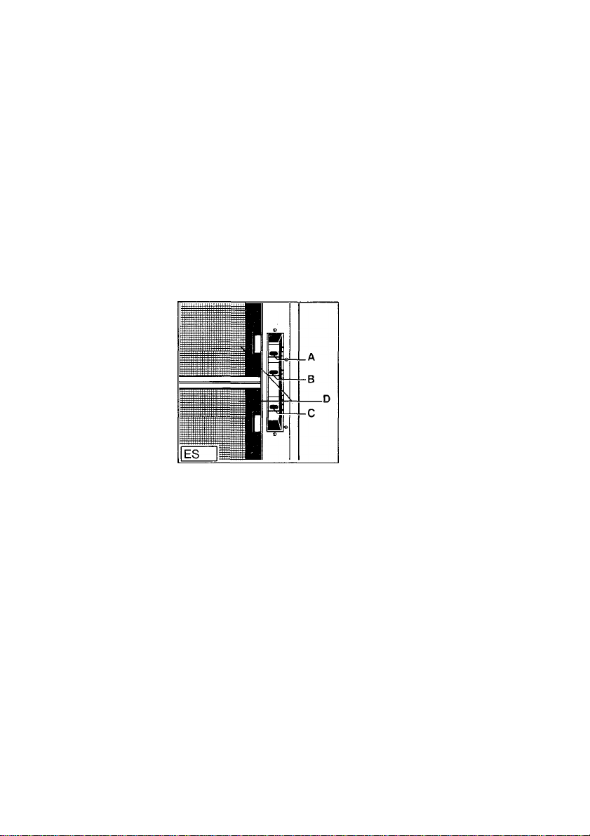
A = Light switch
B = Blower switch (On/Off)
C = Blower switch settings
D = Metal filter grille (fat filter)
The fume extractor hood is switched on and controlled via the
different controls
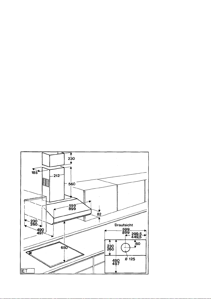
Dimensions:
860 D
Height Width
255 599
Depth
490
(in mm)
30
Weight:
Net:
8609 D
Height
255
Weight:
Net:
22 kg
Width
899
24.5 kg
Depth
497
(in mm)
Page 6
Connection value:
860 D 8609 D
Total connected load: 179 W
Fan motor:
Lighting:
2x 82 W
1 X 15 W
(fluorescent lamp)
180 W
2x 82 W
1 X 16 W
(fl. lamp)
Fan outputs (settings) to DIN 44 971 860/8609 D Setting 1 Setting 2
Exhaust air: 200 mVh 320 mVh 400 nnVh 520 m^/h
Return air: 140 m^/h 240 m^/h 290 m^/h 360 m^/h
Setting 3 Setting 4
Exhaust air system 125 mm dia.
Air outlet arranged centrally above
Pipe connection of 125 mm dia. for exhaust air hoses of 125 mm
dia.
Air outlet
Draufsicht = Plan
31
Page 7
Accessories/installation materials
1 wall rail (for mounting of fume extractor hood)
4 wall plugs for 8 mm, 40 mm long wood screws (for mounting
of chimney retaining plate on wall and wall rail)
4 button-head wood screws, 5 x 40 to DIN 7996
2 wall plugs for 5 mm, 30 mm long wood screws (for mounting
of clamping piece)
2 button-head wood screws, 6 x 30 to DIN 85
1 drilling template for appliance mounting
1 125 mm dia., 800 mm long hose
2 125 mm dia. hose clips for above
1 chimney equalizer (230 mm high)
1 chimney cover plate with air outlet grille for return air
1 chimney retaining plate
1 guide piece (T-piece) for return air operation
4 button-head 2.9 mm x 6.5 mm long sheet metal screws (for
mounting of chimney retaining plate with chimney cover
plate)
3 5x 60 mm screws to DIN 7996 for mounting of wall rail
3 8 x 60 mm wall plugs for wall rail
Preparing for The fume extractor hood is factory-supplied for commissioning
exhaust air in upward exhaust air mode,
operation Prior to installation of the fume extractor hood, a hole should
be arranged in the outer wall for the wall box (return/supply
air) apart from mounting drillholes.
32
Page 8
Preparing the
wall box
(exhaust air
operation)
Position of
exhaust air
opening
33
Page 9
Special
accessories
Exhaust air
hoses
For wall box/fume extractor hood connection, it is best to use
the non-flammable exhaust air hose under E-No. 610899008
(125 mm dia.) from our range of special accessories.
Preparing for
return air
operation
The fume extractor hood is used as a return air hood when no ventilation shaft or outer wall is available.
For operation as a return air hood, it is necessary to install 2
active carbon filters KL600 (E-No. 610899470) for kitchen
fume absorption.
Active carbon filters KL600 are supplied as special accessories
(for your own account).
To insert the 2 carbon filters, proceed as follows:
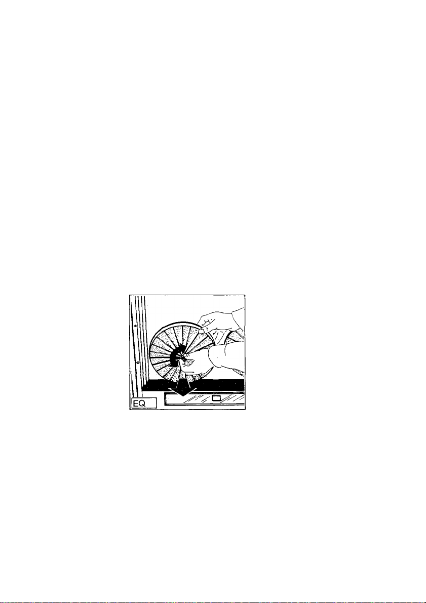
1. Remove metal fat filter grille (Fig. ES/D) (press outwards by
unlocking the locking bolts) (Fig. EW).
2. Remove both knurled screws on the motor shaft (by turning
to the left), place one active carbon filter (round) on each
motor and screw the knurled screws into the motor shafts.
3. Re-insert (re-engage) metal fat filter grille.
The fume extractor hood is now ready for return air operation.
34
Page 10
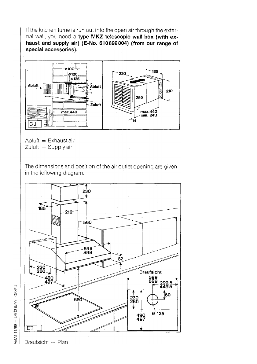
If the kitchen fume is discharged into the open air through the
outer wall, you need a telescopic wall box (E-No. 610899004)
(for your own account from our range of special accessories)
(Fig. CJ).
See the following illustration for the dimensions and position of
the air outlet opening.
To connect the wall box/fume extractor hood, you are recom
mended to use the 125 mm dia. non-flammable exhaust air
hose (E-No. 610899088) (for your own account from our range
of special accessories). The exhaust air connection has a the
oretical opening of 125 mm dia.
Preparing for
exhaust air
operation
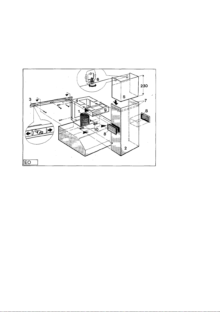
Exhaust air discharged upwards or backwards:
The exhaust air can be discharged through the available moving
hose (accessory) with a sleeve inside the chimney cover plate
(Fig. EO/2) upwards or directly backwards (wail box).
35
Page 11
Wall
mounting
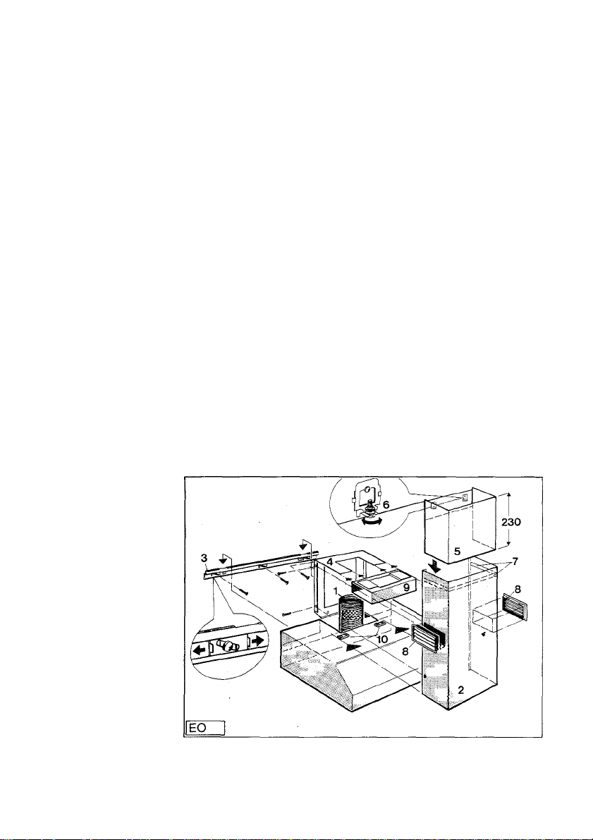
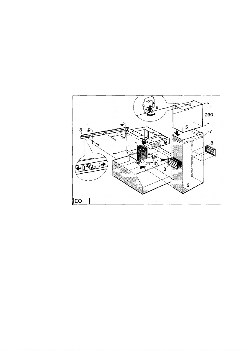
Installation steps for exhaust air operation
1. Hold the installation template (with readable lettering) on the
wall, noting the distance between the upper edge of the hob
and the iower edge of the fume extractor hood!
(Electric/gas cookers 650 mm) (oil and coal cookers min.
700 mm).
2. Mark out and drill the 8 mm dia. holes. Insert the wall plugs
and mount the wall rail (Fig. EO/3).
The wall rail can be horizontally aligned by shifting the sliding
elements.
Important! Oniy use the suppiied 5 x 60 mm screws to DIN
7996!
3. Mount the fume extractor hood in the wall rail and centrally
align about the cooker hob.
4. Insert the chimney retaining plate (Fig. EO/4) in the fume
extractor hood (cutout for exhaust air hose) so that both
angles (above) face forwards (Fig. EO/4). Fix the chimney
retaining plate with 6 8x40 mm wall plugs and 8x 40 mm
screws on the wall.
5. Connect the exhaust air hose (without sleeve) of the fume
extractor hood directly to the wall box behind or directly con
nect 125 mm dia. exhaust air hose to the fume extractor hood
and run on.
36
Page 12

Remove the previously available exhaust air hose!
6. Installing the chimney equalizer (Fig. EO/1) Hush with the
ceiling
Drill holes to take plugs for 5 x 30 mm screws on the RH and
LH sides of the fume extractor hood 50 mm from the lower
edge of the cellling and screw in the screws until they are
5 mm away from the wall.
Turn back the set-screw to Its fullest extent by turning to the
left.
Mount the chimney equalizer (Fig. EO/6) via the wall screws.
Screw in the set-screws by turning to the right until the chim
ney equalizer is applied flush with the ceiling edge.
Maximum equalization height 2.55 m
7. Pull off the foil on the double adhesive tape above in the
chimney cover plate (Fig. EO/7).
8. Slide the chimney cover plate (Fig. EO/2) (with the lateral
ventilation grille) (Fig. EO/8) from the front on to the fume
extractor hood until it engages the holders in the RH and LH
sides.
Firmly press upwards against the chimney equalizer (con
nection by double adhesive tape).
9. Fix chimney cover plate (Fig. EO/2) laterally with 4 2.9 x 6.5
mm sheet metal screws on the chimney retaining plate.
37
Page 13
Additional
installation
work for return
air operation
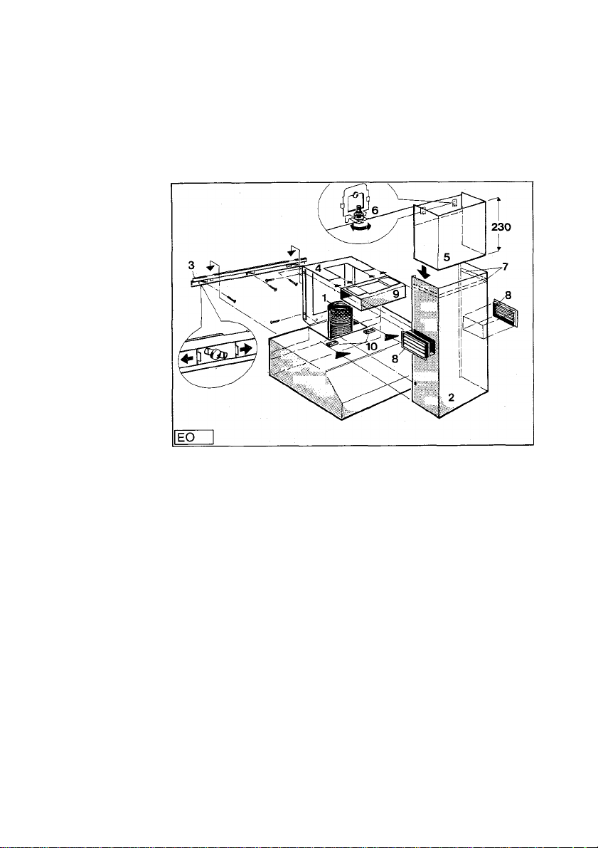
Installation steps same as for exhaust air operation under
points 1 —4
Further installation steps:
5. Slide guide piece (Fig. EO/9) on to chimney cover plate
(Fig. EO/4).
6. Fix exchaust air hose on guide piece with 125 mm dia. hose
clip.
7. Fix chimney equalizer as under exhaust air..
8. Unclip the ventilation grille (Fig. EO/8) from the chimney
cover plate and, after pulling off the foil (double adhesive
tape) (Fig. EO/7), slide the chimney cover plate from the
front on to the fume extractor hood until it engages the hol
ders on the RFI and LH sides (Fig. EO/10).
9. Fix chimney cover plate (Fig. EO/2) laterally with 4 2.9 x 6.5
mm sheet metal screws on the chimney retaining plate.
10. Clip the ventilation grille laterally (on the RH and LH sides)
on the guide piece (Fig. EO/9).
Important! Lamination position obliquely downwards!
Unless this has been done as preparation work, 2 KL 600 car
bon filters (E-No. 610 899 470) (for your own account from our
range of special accessories) must be inserted for return air
operation!
38
Page 14

Allow me to introduce myself: I am your new AEG fume extrac
tor hood. From now on, I should like to help you keep your kit
chen free from fume and fat deposits. Not simply because of my
attractive appearance, but also thanks to my “intrinsic qualities”.
I am economical in terms of energy consumption, quiet, power
ful, easy to operate, and simple to care for. If you carefully read
and follow my operating instructions (maintenance) before first
use, you are sure to be extremely satisfied with me.
Eiectrical connection
Warning t
All appliances with a 3 core lead must bei earthed
Please ensure that the voltage and current indicated on the rating plate
agrees with the voltage of your electrically supply. 220/240 volts — (i.e.
220/240 V a.c.)
Please note! (For users in the U.K.)
If your appliance has been equipped with a mains lead with a moulded
on type plug, you must comply with the following regulations: The plug
moulded on to the lead Incorporates a fuse. For replacements, use a 13
amp BS 1362 fuse. Only ASIA approved or certified fuses should be
used. If'the fuse cover/carrier is lost, a replaoement cover/carrier must
be obtained from eleotrical goods retailers. If the socket outlets in your
home are not suitable for the plug fitted to the appliance, then the plug
must be cut off and destroyed for safety reasons, and an appropriate
plug fitted. When fitting the plug please note the following points:
The wires in the mains lead are coloured in accordance with the follow
ing code:
Green and Yellow Earth
Blue Neutral ■
Brown ' Live
Some appliances have a twin core mains lead, when no earth is
required.
As the colours of the wires in the mains lead of this appliance may not
correspond with the coloured markings identifying the terminals in your
plug proceed as follows:
1. The wire which is coloured Green and Yellow must be connected to
the Earth terminal in your plug, which is marked with the letter E or by
the earth symbol orooloured Green, or Green and Yellow.
2. The wire which is coloured brown must-be connected to the live ter
minal which is marked with the letter Lor coloured red.
3. The wire whioh is ooloured blue must be connected to the neutral
terminal which is marked with the letter N orooloured black.
When wiring the plug, ensure that all strands of wire are securely re
tained in each terminal. Do not forget to tighten the mains lead clamp on
the plug. This appliance complies with the requirements laid out in the
EEC Directive 76/899.
Voltage 220/240 VAC
Fuse rating 13 amps
See rating plate for further information.
Hello
Voltage and
current
electrical
connection
Important
39
Page 15

Safety instructions
For the user
It must be ensured that hobs are always covered so that the
appliance is not damaged by excessive heat liberation. Open
fireplaces on oil-, gas-, and coal-fired cookers must be
avoided.
During deep-frying over a cooker/hob, the appliance used for
deep-frying must also be supervised during operation.
The oil contained in the deep-frying appliance may sponta
neously Ignite through overheating.
If contaminated oil is used, spontaneous ignition may occur
even more readily.
It should be noted that overheating may cause a fire.
Flambe-cooking under the fume extractor hood is not allowed.
During aii work on the fume extractor hood, aiso during lamp
change, the appliance must be de-energized (by removing the
fuses or otherwise disconnecting the appliance).
It is important to observe the filter change or cleaning inter
vals. Failure to observe these Intervals may cause the risk of
fire through fat deposition.
40
Page 16
A = Metal fat filter grille
B = Control panel
C = Lighting
/ \
( 1
1
-------
1 ' '
iEV 1 A C
Appliance
description
B
41
Page 17
First use
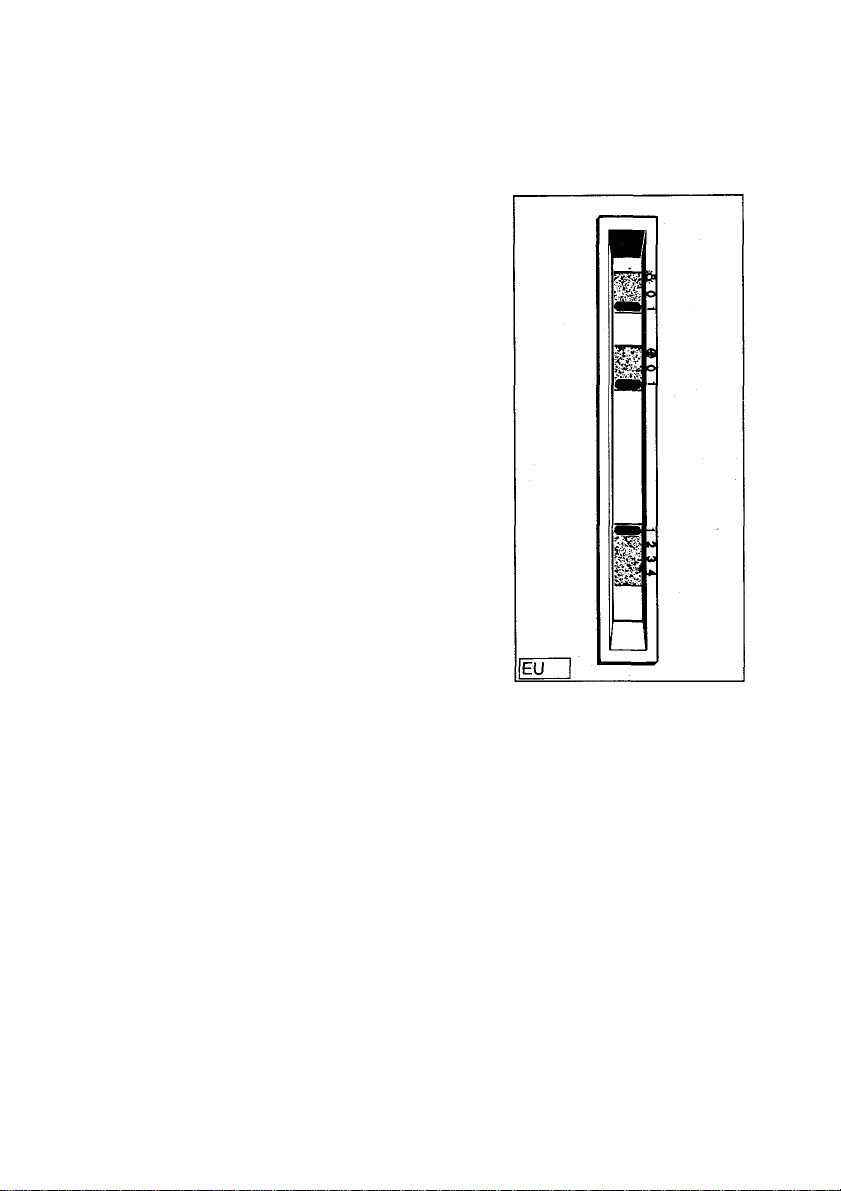
Operation My sliding switches are arranged on the RH side (when viewed
below from the front).
The individual numbers and symbols have the following
meanings (from left to right):
Ql
= Lighting On
= Lighting Off
la
= Lighting
-)S[-
= Blower On
= Blower Off
= Blower setting switch
= Blower setting 1
1
= Blower setting 2
2
= Blower setting 3
3
= Blower setting 4
4
To switch on the fume extractor hood, set my blower switch to
the “On” position g.
The blower of the fume extractor hood runs.
With the blower setting switch §, you can set the fume extrac
tor hood to the power you require (depending on the amount of
fume being generated by the hobs).
You can separately switch my workplace lighting (hobs) on or
off with the On or Off H switch.
42
Page 18

The build-in fume extractor hood is to be switched on before
cooking begins and allowed to run on around 15 minutes after
cooking is completed.
Pre- and
after-running
of fan
You should remove my metal fat filter (Fig. EW) from the ap
pliance every 6 — 8 weeks and wash it by hand or in your dish
washer.
The active carbon filter must be changed not later than after
1 year.
The active carbon filter cannot be washed or regenerated.
Good deodorization is conditional upon a suitable active car
bon volume (depending on the air capacity of your fume ex
tractor hood) and specific arrangement of the active carbon
filter in your fume extractor hood.
This combination ensures a positive return air supply in con
trast to exhaust air operation.
A decisive factor affecting deodorization is what is known as
the dwell time of the aspirated air in the active carbon filter.
This dwell time can only be achieved with the AEG Original
Active Carbon Filter (see Special accessories)
Metal fat filter
Instructions on
active carbon
filter.
43
Page 19
Cleaning the To remove and then clean my metal fat filter grille, proceed as
metal fat filter follows:
For reasons of safety against any unintentional switching on,
remove my screw-in fuse from the holder or switch off my
automatic fusing system in the fusebox.
1. Press the lock on the fat filter grille inwards and detach the fat
filter at the front and rear.
/---------------------------------------.
Hr
Iew
I
2. Clean my internal housing only with warm washing-up liquid
X/
suds (never use any abrasive cleaners, brushes, or scouring
agents).
3. After cleaning, re-insert both dry metal fat filters.
4. Re-insert the fuses and reconnect the appliance.
Active carbon To remove and then replace 2 KL 600 carbon filters (E-No.
filter 610 899 470) (for your own account from our range of special
accessories), proceed as follows:
For reasons of safety against any unintentional switching on,
remove my screw-in fuse from the holder or switch off my
automatic fusing system in the fusebox.
1. Press the lock on the fat filter grille inwards and detach the fat
filter at the front and rear.
44
Page 20
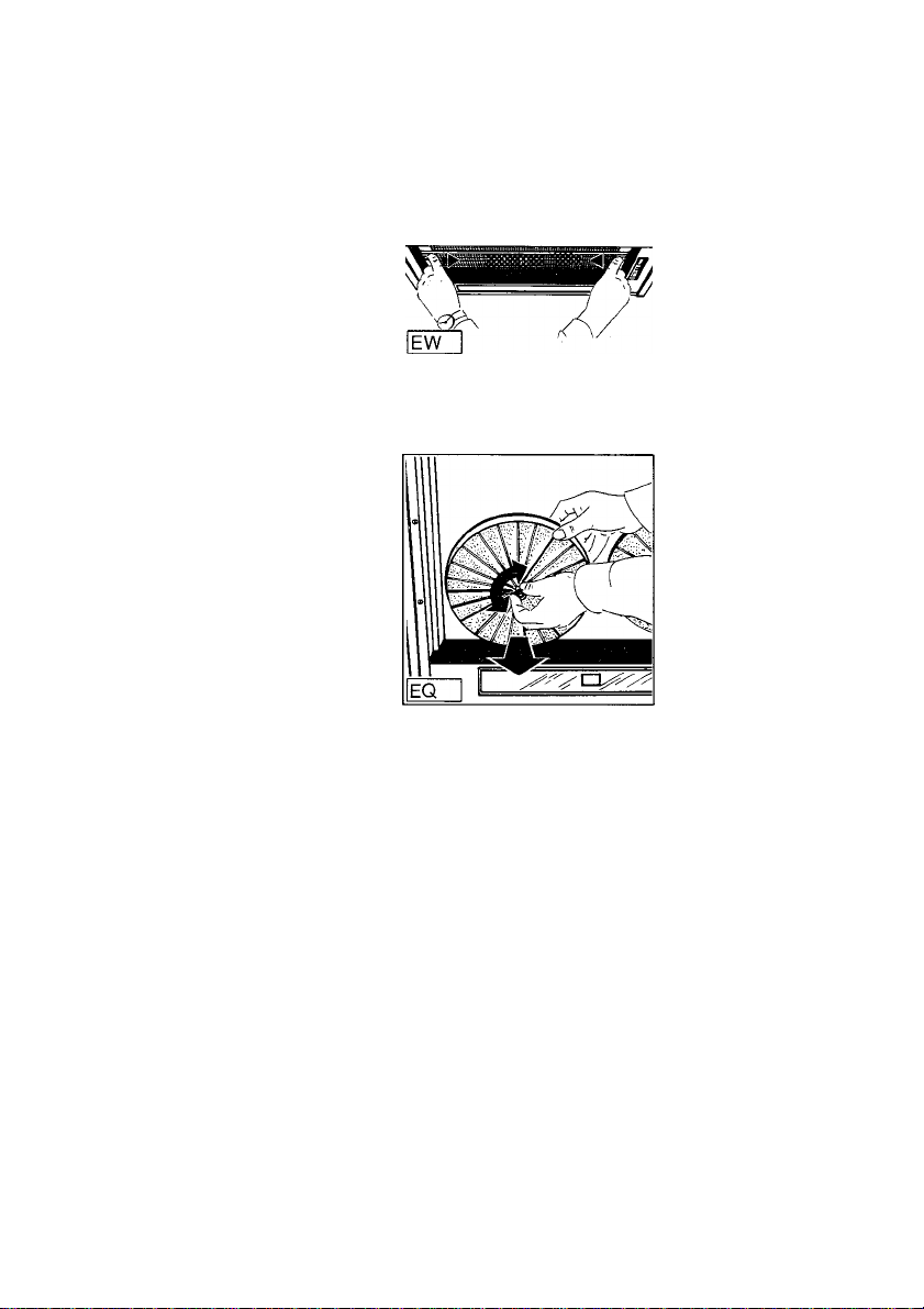
2. Remove old active carbon filters (always 2) by loosening the
knurled screw in the centre.
3. Clean my Internal housing only with warm washing-up liquid
suds (never use any abrasive cleaners, brushes, or scouring
agents).
4. Insert 2 new active carbon filters KL 600. The active carbon
filter is arranged before the motor housing and is mounted
with the knurled screw.
5. Re-insert the fuses and reconnect the appliance.
Your fume extractor hood is now ready to operate in return air
mode again!
45
Page 21
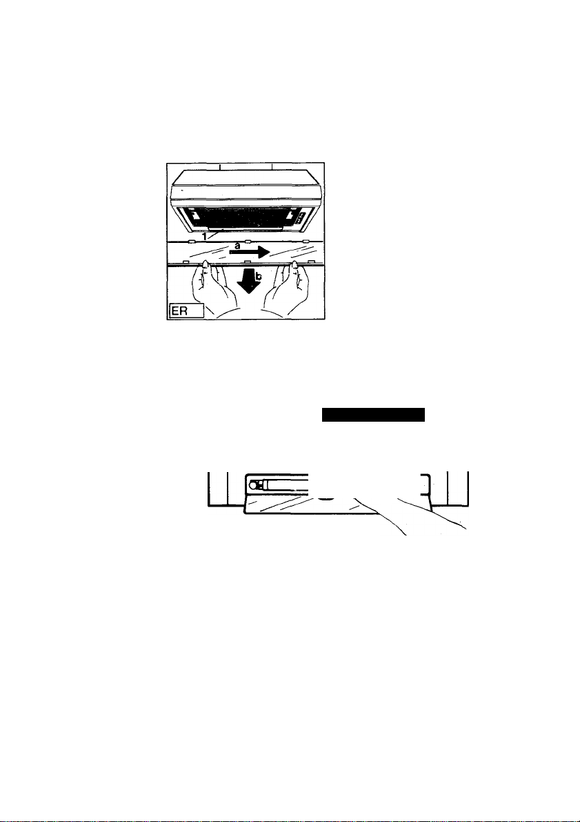
Changing the
fluorescent
lamp (starter)
You can change the fluorescent lamp or starter yourself!
De-energize the appliance before changing the lamp (e.g. puli
out the mains plug).
1. Slide the lighting cover to the right (860 D) or unclip and de
tach it (8609 D).
2. Unscrew my defective fluorescent lamp by twisting out of the
sockets to the left and replace it with a new one.
46
DF
Important: Insert only a max. 15 W (860 D) or 16 W (8609 D)
fluorescent lamp by twisting into the sockets to the right!
Page 22
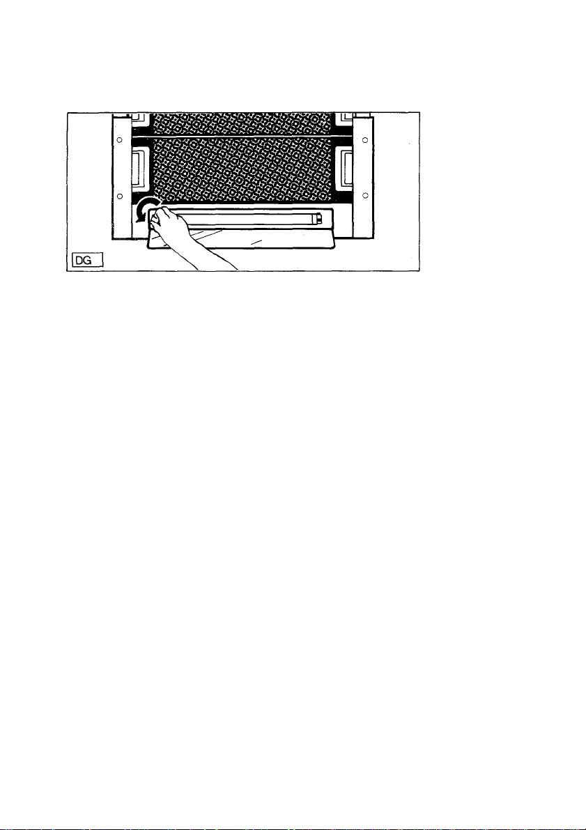
3. Remove any defective starter by twisting out of the socket to
the left.
Insert a new starter by twisting to the right.
4. Reclose my lamp cover. Re-insert the fuses and reconnect
the appliance.
important! To ciean the fume extractor hood, de-energize the
appliance (e.g. pull out the mains piug). Never introduce sharp
objects into the protective griiie of the motor!
Clean the outer parts with a mild washing-up liquid solution.
Never use abrasive cleaners, brushes, or scouring agents.
Clean the control panel screen and fat filter grille only with a
damp cloth and mild washing-up liquid solution.
It is important to observe the filter change or cleaning inter
vals. Failure to observe these intervals may cause the risk of
fire through fat deposition.
Cleaning
47
Page 23

Special accessories
Active carbon filter KL 600
(2 units)
Wall box MKZ
(External dimensions
Opening
Exhaust air hose
125 mm dia., aluminium
E-No. 610 899 470
E-No. 610 899 004
Height X width in mm
250 X 220
185x210)
E-No.610 899 008
48
Page 24

Customer service
In case of any enquiries and faults, please call our service centre
(see list of service centres).
When calling, please state the following;
1. The model designation
2. The E-No.
3. The F-No.
You will find these data on the nameplate after opening the fat
filter grille Inside the appliance.
In the interests of technical progress, the manufacturer reserves
the right to make design and colour alterations without prior
notice.
49
 Loading...