

Page 1
Please read this manual carefully and thoroughly before any
attempt to install and operate this product and retain it for your
future reference.
User's Manual
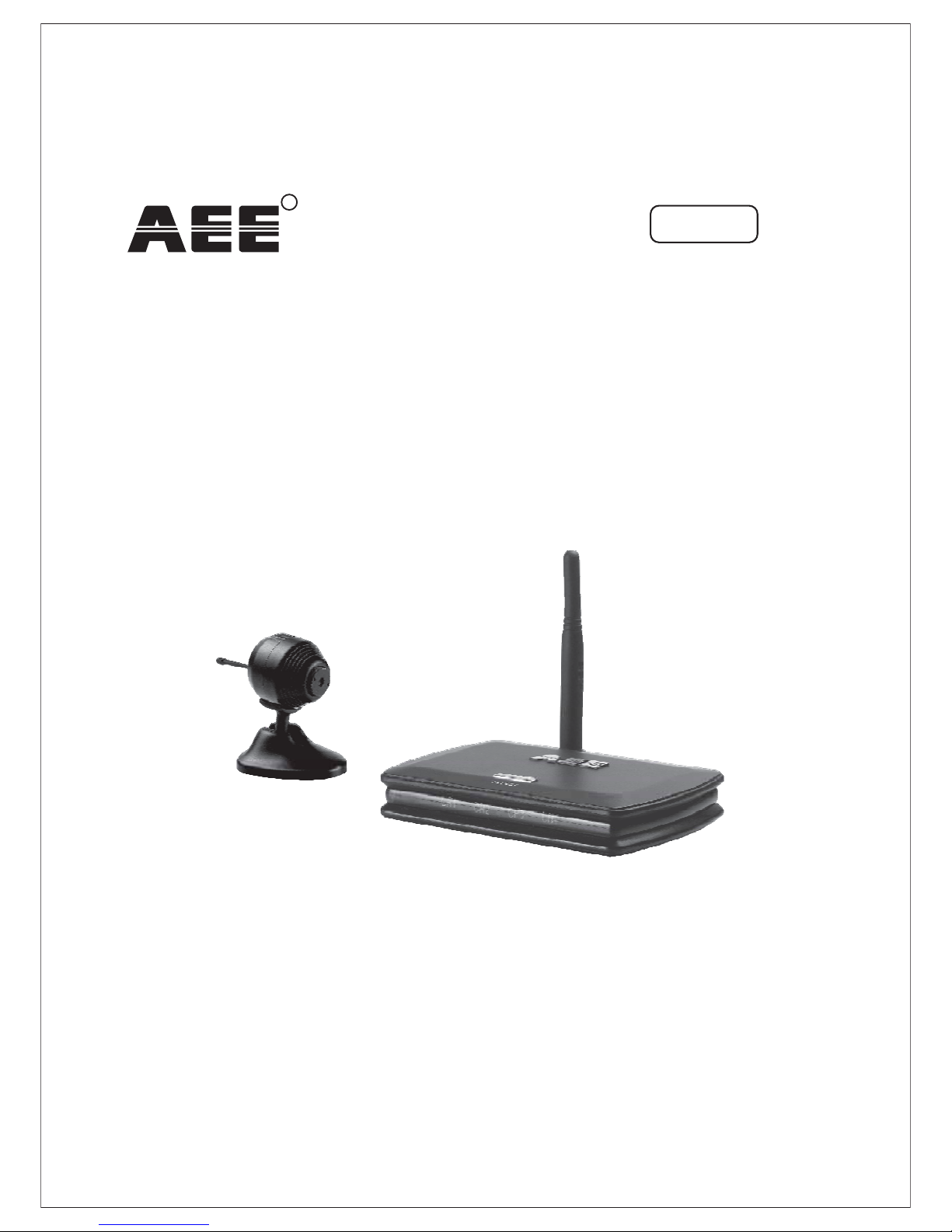
2.4GHz Color Wireless Camera Kit
MODEL: A101
English
R
Page 2
EU Environmental Protection
Waste electrical products should not be disposed of with
household waste. Please recycle where facilities exist.
Check with your Local Authority or retailer for recycling
advice.
Page 3

TABLE OF CONTENTS
SPECIFICATIONS
14
TROUBLESHOOTING
15
PRODUCT
5~7
Package Contents
Feature Locations
Adapter & Battery Clip
5
6
7
INSTALLATION & USAGE
8~13
Installation
Fix the Camera
Camera Channel Setup
Receiver Mode Setup
8~10
12
12
13
Locate the Receiver
INTRODUCTION
1~4
Notice
Restrictions
Maintenance
Warranty
Copyright
Approval Information ( )
FCC/CE
1
3
3
4
4
1~2
11~12
Page 4

Page 5

INTRODUCTION
Thank you for your interest and support in our product and purchasing
this wireless camera kit. This product
eel confident that you will be pleased with the quality and features
of this product.
The camera features one CMOS image sensor and a transmitting
module to capture the image and transmit them wirelessly.
The receiver features a receiving module to receive and output AV
signals.
works at ISM-2.4GHz frequency
band, which could be legally used worldwide without permission.
We f
Notice
Notice: This product may cause interferences with other wireless
equipment that operates at 2.4GHz ISM band. Please turn off one of
the equipments to eliminate the interference.
Product Assurance:.This camera will emit electromagnetic wave,
just like other wireless products. But its transmitting power is lesser
than other wireless products such as mobile phones. The 2.4GHz
wireless camera meets wireless frequency security standards and
recommended indexes while working. These standards and indexes
are certificated by academic organization and represent the cogitative
research of the scientific workers who continuously explore and
annotate the involved fields. So we believe that our products are safe
for customers
1
All our products meet the requirements of FCC or CE, and
are granted the FCC or CE
approval
certification. They are authorized to bear
FCC or CE mark.
Approval Information
Page 6

After testing the product, we confirm that it complies with the provision
for class C digital equipment in the 15th part in FCC regulation; and
the receiver complies with the limitations for class B digital equipment
in Part 15 of FCC regulation. The product generates, applies and emits
radio waves. It might cause harmful interferences to wireless
communication if not be installed and used following the description
of the manual. The product may cause interference in residential area,
and the customer should take remedies to eliminate the interference
at their own costs. If the product causes any harmful interference to
wireless equipment or disturbs the receiving of TV signals (it can be
identified by turning on and off the product), you can solve the trouble
by following methods:
FCC
This product complies with standards including ow oltage evice
Directive 73/23/EEC; Directive 89/336/EEC and
Directive 1999/5/EC. It passed the subject tests by the authority
concerned and is authorized to bear mark.
LV D
EMC R&TTE
CE
CE
2
This product meets the requirements specified in Part 15 of FCC
Regulation. Operation rests with the following two conditions:
(1) The equipment should not cause any harmful interference;
(2) The equipment must receive and process any interference,
including any possible interference caused by operation
mistakes.
(1) Readjust the product or put it in another place;
(2) Extend the distance between the equipment interfered and the
product; and
(3) Refer to dealers or experienced radio electrician for help.
Page 7

Copyright
This manual is furnished under license and may be used or copied
only in accordance with the terms of such license. Except as permitted
by such license, no part of this publication may be reproduced, stored
in a retrieval system, or transmitted, in any form or any means,
electronic, mechanical, recording, or otherwise, including translation
to another language or format, without the prior written permission of
AEE Technology.
The content of this manual is furnished for informational use only, is
subject to change without notice, and should not be construed as a
commitment by AEE Technology.
AEE Technology assumes no responsibility or liability for any errors or
inaccuracies that may appear in this booklet. All other product names,
trademarks and registered trademarks in this document are the
properties of their respective holders.
Warranty
AEE Technology warrants that this product will be free from defects
in materials and workmanship for period of time specified. This
limited warranty shall commence from the date of purchase.
product warranty is not transferable and is limited to the
original purchaser. If the product is found to be defective then, as
your sole remedy and as the manufacturer's only obligation,
will repair or replace the product. This warranty shall not
apply to products that have been subjected to abuse, misuse,
abnormal electrical or environmental conditions, normal wear and
tear or any condition other than what can be considered normal use.
Should you have problems, please consult the local dealer.
AEE
Technology 's
AEE
Technology
3
Page 8

DO NOT use this product to violate one's privacy. Monitoring one's
activities without consent is illegal and this product is not designed
and manufactured for such purpose;
DO NOT put this product near any medical equipment. Radio
waves might potentially cause breakdown of electrical medical
equipment. So this product should be placed at least 1 feet away
from any heart pacemaker. Radio waves might potentially
influence heart pacemaker and lead to respiratory disturbance;
DO NOT use this product for any illegal activities. AEE Technology
shall not be responsible for any consequences of illegal acts
committed by the user.
1.
2.
3.
Restrictions
Ensure the sufficient ventilation space is available;
Do not shake or strike the product;
Keep it dry and dustless and avoid exposing it to direct sunlight;
Do not place product near any magnetic objects;
Avoid putting the product in places where the constantly changed
temperature or humidity occurs;
Keep product away from heat sources such as electric heater;
Do not use the camera near aggressive chemicals;
Do not use this camera near water, for example, near a bath tub,
wash bowl, kitchen sink or laundry tub, in a wet basement or near
a swimming pool and the like;
Do not use the camera in the places which are enclosed by metal.
The surrounding metal like lifter, cabin, may shield the
electromagnetic wave, and result in failure of signal reception;
Please obey the local government's environment protection policy;
Please turn off the power when left unused;
Do not disassemble or repair the camera or receiver; doing so
might cause damages to the product.
1.
2.
3.
4.
5.
6.
7.
8.
9.
10.
11.
12.
Maintenance
4
Page 9

5
This package comes with the following items. Please check whether
they are all included in the packaging box, if one or some is missing,
contact the retailer for replacement.
Package Contents
PRODUCT
Note:
1. This product can be either black or silver.
2. The pictures may vary from the actual
objects.
Wireless camera 1
1
Wireless receiver 1
2
Mounting plate for camera 1
3
Holder for receiver 1
4
Antenna for receiver 1
5
DC 7.5V power adapter for
camera 1
6
DC 7.5V power adapter for
receiver 1
7
AV cable 1
8
Lens adjuster 19
Mounting hardware 1
10
User's manual 1
11
Battery clip 1
12
1
2
3 4
5
6
7
8
9
10
11 12
Page 10

Feature Locations
1. Camera
2. Receiver
Antenna
Lens
Universal
Bracket
DC Power Jack
MIC Hole
Channel
Switch
Mode Control
DC Power Jack
AV Output
Antenna
Channel Indicator
Channel Select/Mode Switch Button
6
Page 11

7
This product always conforms to the authenticated AC adapter. The
adapter should be marked one of the following:
Note:
When using the power adapter, make sure the rating voltage on it is compatible
with that of the device to avoid potential damages resulting from incorrect usage
of power supply.
UL Mark
American power
supply authentication
SAA Mark
Australia power
supply authentication
GS Mark
German power
supply authentication
CCC Mark
China power
supply authentication
European Union power
supply authentication
CE Mark PSE Mark
Japan power
supply authentication
Adapter
Battery Clip
With the supplied battery clip, the camera could be powered by
battery of the same voltage for temporary use.
Battery
Battery ClipCamera
Page 12

8
1. Connect the power jack of adapter ( 0mA) or battery
with battery clip to camera.
DC 7.5V 30
2. Connect the antenna to the receiver.
3. Connect the receiver to the monitor/TV with AV cable. (Red socket
for audio; yellow socket for video). Turn on the monitor/TV and
select AV mode.
Installation
INSTALLATION & USAGE
a. Connect with adapter
b. Connect with battery clip
Page 13

4. Connect the power jack of adapter ( 300mA) to receiver.
Slide switch to and
DC 7.5V
position the channel indicator
lights up green.
Mode Control M
OFF-M-LOFF - M - L
* The receiver provides ( ) mode, mode ( ) and
mode ( ). Please refer to section for
more details.
Power Off OFF Manual M
Channel Scan L Receiver Mode Setup
5. Set the camera to one desired channel.
12 3 4
Default Setting
9
6. Press the channel select button on the receiver until the channel
indicator matches to the channel on the corresponding camera.
And the monitor/TV will display pictures.
Channel Select Button
Page 14

9. Adjust the brightness, contrast and color setting of the monitor/TV
to get the best display effect.
7. If the picture is blur. You could adjust the lens focus with lens
adjuster to make the picture clear.
8. Mount the camera to a desired location.
Desktop Wall Mount
Ceiling Mount
10
Lens Adjuster
Page 15

Fix the Camera
Mounting Plate
Please follow the steps below if you want to fix the camera to wall or
ceiling.
1. Fix to Wall
1.1 Secure the mounting plate to wall with screw;
1.2 Hang the camera on the hooks of mounting plate;
1.3 Push downwards the camera firmly.
Hook
2. Fix to Ceiling
2.1 Detach the universal bracket from the camera and then install it to
the camera top for avoiding reverse picture;
2.2 Secure the mounting plate to ceiling with screw;
2.3 Hang the camera on the hooks of mounting plate;
2.4 Push left the camera firmly.
11
1.1 1.2 1.3
2.1
Push Bracket
Page 16

Locate the Receiver
The receiver can be placed horizontally or vertically. When it is placed
vertically, the supplied holder is required.
12
Horizontal Vertical
Holder
This camera has 4 selectable channels to avoid possible interference
from other nearby wireless devices.
Camera Channel Setup
1234
Default Setting
CH1=2,414MHz;
CH2=2,432MHz;
CH3=2,450MHz;
CH4=2,468MHz
Channel Frequency
Hook
Mounting Plate
2.2
2.3
2.4
Page 17

Note:
only
When entering channel scan mode through manual mode, you could exit by pressing
channel select button; while entering through selection, you could exit by sliding the
switch to or .
L
Mode Control M OFF
Receiver Mode Setup
The receiver can support up to 4 cameras working at the same time.
It provides mode ( ), mode ( ) and
mode ( ).
Power Off OFF Manual M Channel
Scan L
CH1
CH2
CH3
CH4
CH1
CH2
CH3
CH4
5s
5s
5s
5s
Channel Scan Mode
OFF-M-LOFF - M - L
3. mode: Slide switch to or press and
hold the channel select button more than 5s in mode to
enter channel scan mode. In channel scan mode, all the channels
will display one by one looping in turn per 5s.
Channel Scan Mode Control L
Manual
1. mode: Slide switch to to power the
receiver off;
Power Off Mode Control OFF
2. mode: Slide switch to to enter
mode. In manual mode, the receiver channel won't change until you
press the channel select/mode switch button;
Manual Mode Control M Manual
13
OFF-M-LOFF - M - L
OFF-M-LOFF - M - L
Page 18

SPECIFICATIONS
* Specifications are subject to minor change without prior notice.
14
Items Value
Transmission Frequency
ISM 2,400 z~ 2,483MHzMH
Antenna Type
Omni
Power Supply
DC 7.5V 300mA
Storage Humidity
85% RH
Storage Temperature
Imaging Sensor
1/3-inch CMOS
CMOS Total Pixels
628 582 (PAL)/ 510 492 (NTSC)
S/N Ratio
40dB (AGC OFF)
Horizontal Resolution
380 TV Lines
Minimum Illumination
5 Lux/F1.2
Transmission Power
10mW (CE)/2mW (FCC)
Transmission Distance
100m (Without Block)
Consumption Current
80 mA (Max.)
Dimensions (WxDxH)
28mmx30mmx28mm (Main Body)
Weight
Approx.22g (Main Body)
Receiving Sensitivity
-85dBm
Consumption Current
240mA (Max.)
Video Output Level
Audio Output Level
Dimensions (WxDxH)
Weight
Approx. 99g (Main Body)
Operating Temperature
100mmx70mmx18mm (Main Body)
Camera
Receiver
-20 C~+60 C /-4 ~+140
ooo o
FF
-10 C~+50 C /+14 ~+122
ooo o
FF
Power Supply
DC 7.5V 300mA
1V @10k
p-p
1V @75
p-p
Page 19

TROUBLESHOOTING
When you experience the operation problems, please check and try
the following yourself before claiming that it is the defective product
or consulting the experienced technician.
15
Abnormal Phenomena
Possible Reasons/Solutions
Check whether the camera/receiver
is connected to power supply and
powered on.
1. Check if the channel of receiver is
the same as that of camera;
2. Check the distance & blocks.
Mismatching the TV system of PAL
or NTSC.
1. with other devices;Interfered
2. Check the distance & blocks.
Adjust the lens of camera.
Interfered with other devices nearby;
Remove or turn off such devices.
No image
Snowflakes
on image
Normal image
No color
Ghost image
Blur image
No sound
Noisy
Noisy
Normal sound
Normal sound
Normal sound
Page 20

AEE TECHNOLOGY CO.,LTD
R
 Loading...