

Page 1
Model: CAM325
Wired Bumper or Butterfly Mounted
Camera
Installation Manual
Features
• Very Small Compact Camera
• High Resolution, ¼ inch CMOS Color Camera
• Waterproof Housing
• 160 Degree Wide View Angle
• Selectable Image: Normal/Reverse
• Multiple Camera Mounts including Flush bumper mount and
adjustable butterfly mount.
• DC12V – DC24V
Page 2

Table of Contents
Warnings......................................................................................3
Product Description .....................................................................4
Packing List .................................................................................4
Camera Installation ...................................................................... 5
Camera Wiring Diagram..............................................................8
Specifications ..............................................................................9
Troubleshooting ........................................................................... 9
2
Page 3

Warnings
The product is intended to assist in safe driving and to allow the driver to
have a broader rear view while the vehicle is in reverse. You, as the
driver, are solely responsible for the safe operation of your vehicle and
the safety of your passengers according to local traffic regulations. Do not
use any features of this system to the extent it distracts you from safe
driving. Your first priority while driving should always be the safe
operation of your vehicle. Audiovox Electronics Corporation cannot
accept any responsibility whatsoever for accidents resulting from failure
to observe these precautions or safety instructions.
1. This product utilizes high voltage. Any unauthorized modifications or
damage to the product may result in electrical shock. Handle all
components with care. Inspect regularly for damage to components
and cabling.
2. You are responsible for ensuring that the installation of this product
does not void or affect the vehicle manufacturer’s warranty.
Audiovox Electronics Corporation or its subsidiaries are not liable in
full or in part for improper installation resulting in loss or damage to
your property, or for voiding all or part of the vehicle manufacturer’s
warranty.
3. Do not apply excessive force to any of the components contained
within this kit. Excessive force used before, during or after
installation that results in a damaged or non-functional part will void
all warranties.
4. Please follow the procedures in this installation manual. Improper
installation or modification of this product will void all warranties.
3
Page 4

Product Description
This new camera system gives you two mounting options for installing a
backup camera onto the rear of your vehicle (surface butterfly mount and
in bumper flush mount).
This Wired Camera is compatible with most monitors/TFT screens and
can be connected using a standard RCA connector.
Packing List
Parts
Camera 30232390 1
Power Cable & Adaptor Cable
Mounting Screw
Mounting Brackets 30232060 1
Manual 30232020 1
Barcode # Quantity
30232160
30232010
1
1
4
Page 5

Camera Installation
Butterfly Mounting Instructions
1. Assemble the camera – ensure that the top of the camera marked with
an alignment arrow and the word “UP” is aligned with the notch in
the metal bracket.
2. Decide on a suitable mounting position.
3. Examine the vehicle to determine the best way to run the power wires
to the reverse lights and the extension cable through the car.
4. Mount the camera using the provided bracket and screws – the
bracket can be bent to suit different mounting angles.
5. Route the camera wiring into the vehicle. The wire can be run through
an existing grommet, behind a tail lamp, under the trunk molding, or
if necessary, through a 5/8 inch hole drilled near the vehicle’s rear
license plate. When choosing a wiring path, make sure the cable
will not be damaged or pinched, as this may cause a short circuit
that is not covered by the warranty. If drilling a hole, perform the
following steps:
a) Acquire a 5/8 inch drill bit, rust preventive, all of which can be
purchased at a hardware store.
b) Check behind the intended drilling location before drilling to
verify that no wires or mechanisms can interfere with or be
damaged during drilling.
c) Check for interference with license plate lights and the hatch
release switch and/or mechanism.
5
Page 6

d) Drill a 5/8 inch hole at the selected location.
e) Coat the edge of the hole with rust preventative.
f) Route the camera cable through the grommet and then through
the hole.
g) Insert the grommet in the hole to keep water from entering the
vehicle.
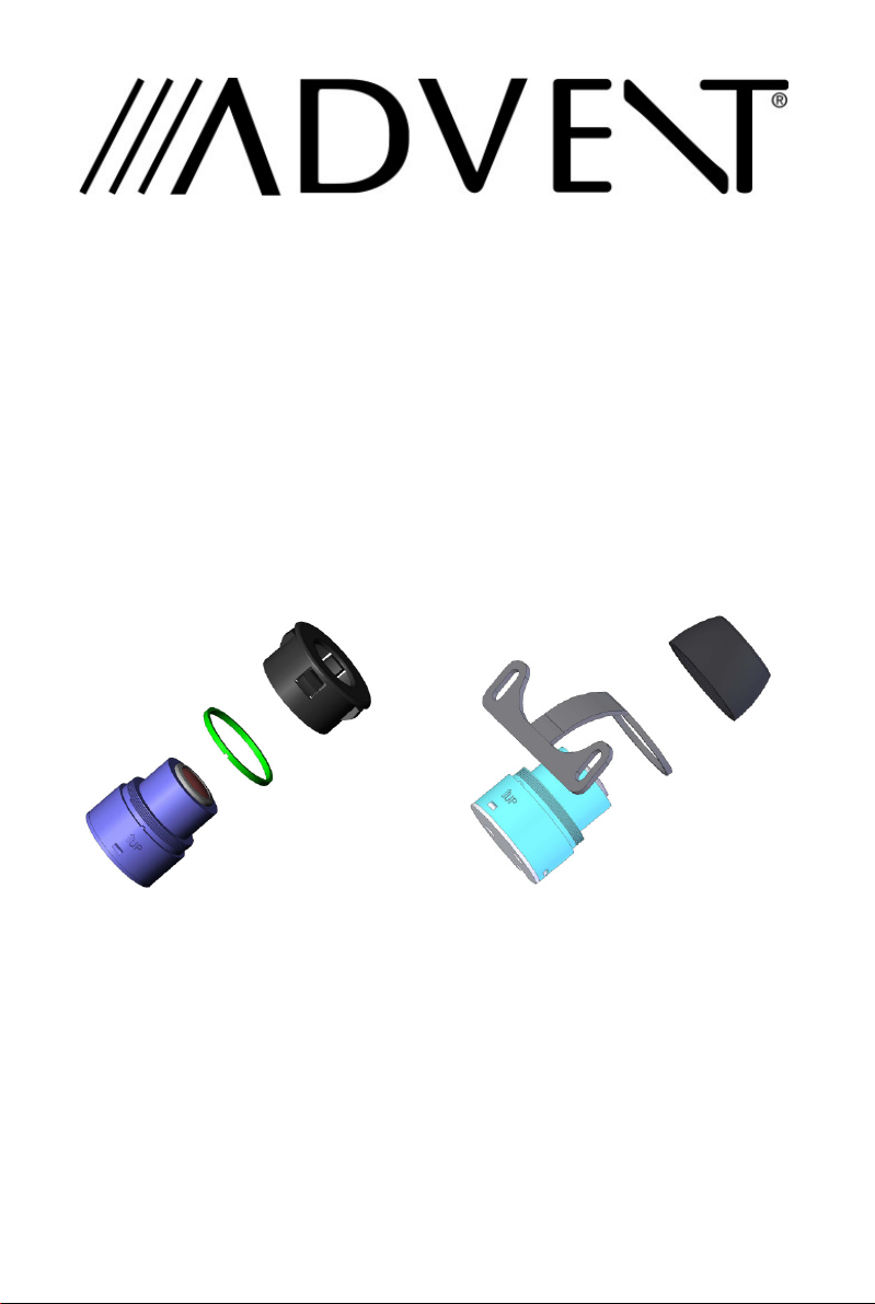
Flush Mounted Mounting Instructions
1. Assembly the camera. Ensure that the spacer ring is installed before
the flush mounting supporter is screwed on.
2. Find a suitable location on the bumper (preferably in the center)
where there is enough space behind the bumper for the camera.
3. Verify that the planned mounting location is accessible from behind
and that you have access to route the wiring inside the vehicle.
4. Drill a 1” Diameter hole in the bumper and mount the camera. Use
the alignment arrow and “UP” text to ensure the camera is mounted
upright and level.
5. Be sure the press the camera in around the edges. Do not press
directly on the lens.
6. Route the camera wiring into the vehicle. When choosing a wiring
path, make sure the cable will not be damaged or pinched, as this
may cause a short circuit that is not covered by the warranty.
6
Page 7

Wiring the Camera to the Vehicle’s Reverse Lamp
1. Locate the reverse lamp in the tail light assembly.
2. Using the tap connector supplied, perform the following steps:
a) Place the un-stripped positive lead from the tail lamp in the run
channel, which runs completely through the connector.
b) Insert the un-stripped red power wire from the camera
completely into the other channel in the connector.
c) Make the connection between the wires by crimping down the
metal connector with a pair of pliers, making sure the metal is
flush with the plastic insulator.
d) Close the top plastic hinged cover until latched.
3. Attach the black wire to the ground (negative).
4. Repeat the above steps for the red wire.
Connecting the Video Signal
1. If used with an Advent LCD Monitor such as LCD4WM or LCDM42
the camera power and signal will be provided through a single cable
to the monitor (supplied with the monitor).
2. If using an alternative monitor, use the adaptor harness to split the
signal to RCA connections then connect to the female RCA input on
the alternative monitor.
7
Page 8

Reverse/Normal Image Adjustment
The camera comes standard with a reversed image, designed for mounting
at the rear of the vehicle. If you need to change to a forward or normal
image view, clip the blue jumper wire loop on the wiring cable to change
the camera image to normal. Secure the clipped wires with electrical tape.
To change back to reverse image view, reconnect the blue wires and
secure with electrical tape.
Camera Wiring
Note: If used with an Advent LCD Monitor such as LCD4WM or
LCDM42 the camera power and signal will be provided through a single
cable to the monitor (supplied with the monitor).
8
Page 9

Specifications
1. Voltage: DC9v – DC24v
2. Current: 50 mA
3. Signal System: NTSC
4. Image Sensor: ¼” CMOS Sensor
5. Horizontal Resolution: 480 lines
6. Viewing Angle: 160 degrees
7. Minimum Illumination: 0.7 Lux
8. Image Display: Selectable Normal/Reverse Image
9. Adjustable Viewing Angle
10. Dimensions:
• Camera: 26mm W x 30mm L
• License Plate Bracket: 196mm W x 36mm H
Troubleshooting
Symptom Solution
No video signal appears while
reversing the vehicle
Video image is not sharp enough Clean the camera lens.
1. Check the rear view camera
lens and clean if needed.
2. Check the rear view camera
wiring connection and RCA
connection.
3. Check the Fuse – if blown
replace ONLY with fuse of
equal amperage.
9
Page 10

7
Page 11

© 2008 Audiovox Electronics Corp., 150 Marcus Blvd., Hauppauge, N.Y. 11788
8
 Loading...