

Page 1
09/2 3/2013
AIR CONDITIONER & HEAT PUMP
DIGITAL CONTROL FOR DUCTED SYSTEM
INSTALLATION AND OPERATING IN STRUCTI ONS
FOR ACM1 35 , ACM 135SP,A CM150 ,A CM150SP,A CRG15 ,A CTH12
RECOR D TH IS U NIT INF OR MATI ON F OR FUTU RE R EF ERENC E:
Model N um be r:
Seria l Nu mb er:
Date Pu rc ha sed:
This ma nu al m ust be re ad a nd unde rs tood befo re i nstal la tion, adj us tment , se rvice, or m ai ntena nc e
is perf or me d. Th is u nit mus t be i nstalle d by a q ualif ie d service t ec hnici an . Modif ic ation of th is
product c an b e extre me ly haza rd ous and cou ld r esult i n pe rsonal in ju ry or pro pe rty damag e.
ROOM AIR
CONDITIONER
3TY1
Page 2
INSTALLATION & OPERATING INSTRUCTIONS
These instructions must stay with the unit
Safety Instructions
This manual h as s af et y information a nd i ns tructions to he lp u se rs eliminate or r ed uc e th e risk of
accidents a nd i nj ur ies.
Read and foll ow a ll s af ety informati on , in stallation gu id es , re commended p re ca ut ions, and safe
operating i ns tr uc tions.
GENERAL INFORMATION
A. Thi s air conditi oner / heat p ump is design ed for:
1. Ins tallation o n a recreat ional vehic le.
2. Mou nting on the ro of of a recre ational veh icle.
3. Roo f construct ion with ra fters/joi sts on 16 inc h centers.
4. 2.5 " to 5.5" inch th ick roofs .
B. The e ffic iency of th e air conditi oner / heat p ump will be affec ted by the
cond itions insi de and outs ide of the RV. Redu cing the he at gain of the RV wil l
allo w the air condi tioner / he at pump to func tion with g reater effici ency. Here
are so me suggesti ons to redu ce heat gain in y our RV.
1. Sel ect a shaded ar ea to park yo ur RV
2. Clo se windows an d utilize t he blinds and / o r curtain s.
3. Kee p doors shut.
4. Avoid us ing applian ces that prod uce heat.
Beginning the cooling / heating process early in the day will greatly improve the heat pump’s
ability to maintain the desired temperature.
In high temperature and high humidity environments, the air conditioner / heat pump should be
set in Cool mode with the Fan Speed in the high position, This will allow for optimal cooling
efficiency.
C. Con densation
The ma nufacture r of this air c onditione r / heat pump w ill not be resp onsible f or
dama ge caused by co ndensed m oisture on ce ilings or o ther surfac es, Air cont ains
mois ture and this m oisture t ends to conde nse on cold s urfaces, Wh en air enters
the RV, co ndensed m oisture may a ppear on the ce iling, wi ndows, meta l parts, et c.
The ai r condition er / heat pum p removes thi s moistur e from the air du ring cool ing
oper ation, Keep ing doors a nd windows cl osed when t his air condi tioner /h eat
pump i s operating w ill minim ize condens ation.
THERMOS TAT ERROR CODE TAB LE
CAU SE SOL UTION
DIS PLAY
Er
Dip S witch p ositi on inco rrect
E1
Roo m Temp Sen sor Def ect
E2
Ind oor Coi l Temp Sen sor Def ect
Out door Co il Temp Se nsor De fect
E3
E4
Out door Amb ient Tem p Senso r Defec t
E5
Com munic ation D efect w ith T-St at and Re lay Kit
DC vo ltage i s below 1 0 Volts( +/-0. 5V)
Lo
dF
Ind oor or Ou tdoor c oil is fr ozen
Set D ip swit hces to c orrec t posit ion on ba ck of The rmost at
Rep lace Th ermos tat
Che ck wire c onnec tions a nd ensu re sens or is pro perly i nstal led.
Rep lace Se nsor
Che ck wire c onnec tions a nd ensu re sens or is pro perly i nstal led.
Rep lace Se nsor
Che ck wire c onnec tions a nd ensu re sens or is pro perly i nstal led.
Rep lace Se nsor
Che ck wire c onnec tions a t T-Stat a nd rela y kit
Che ck wire c onnec tions a nd ensu re DC vol tage is a bove 10 v olts
Sys tem is de icing a nd can no t be used f or 35 min utes an d will re start
aut omati cally
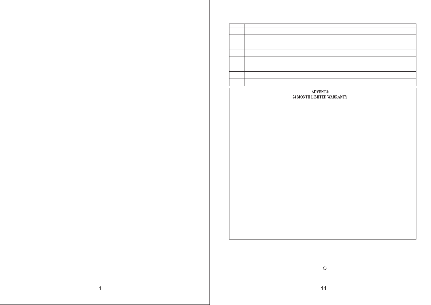
ASA Electronics (ASA) warrants to the original retail purchaser of this Advent product that should this product or any
part thereof, proven defective in material or workmanship within 24 months from under normal use and conditions, be
the date of original purchase, such defect(s) will be repaired or replaced (at ASA'S option) without charge
for parts and repair labor.
The intended use of this Advent product is on recreational vehicles, also known as motorhomes and travel trailers.
Any installa be considered normal use and warranty coverage will not tion outside of this intended use is not to
be expressed warranty condition of improper installation. extended under the
To obtain repair or replacement within the terms of this warranty, contact ASA at (888) 283-7374. The product is
to be delivered with proof of warranty coverage (dated bill of sale), specification of defect(s) with purchaser’s
name and return address, transportation prepaid to ASA at the address shown provided at the time of return
authorization.
This warranty does not extend to the effects of this device on other devices, to costs incurred for removal or
reinstallation accessories, or electrical system(s). This warranty does of the product, or to damage of any product,
not part thereof which, in the opinion of the company, has been damaged through apply to any product or
alteration, i ndling, misuse, neglect, or accident. mproper installation, misha
THE EXTENT OF ASAS LIABILITY UNDER THIS WARRANTY IS LIMITED TO THE REPAIR OR
REPLAC NO EVENT, SHALL ASAS LIABILITY EXCEED THE EMENT PROVIDED ABOVE, AND, IN
PURCHASE PRICE PAID BY THE PURCHASER FOR THE PRODUCT.
This warranty is in lieu of all other express warranties or liabilities. ANY IMPLIED WARRANTIES, INCLUDING
ANY MERCHANTABILITY, SHALL BE LIMITED TO THE DURATION OF THIS IMPLIED WARRANTY OF
WARRANTY. ANY ACTION FOR BREECH OF ANY WARRANTY HEREUNDER INCLUDING
WARRANTY BROUGHT WITHIN A PERIOD OF 30 DAYS FROM OF MERCHANTABILITY MUST BE
THE DATE OF PURCHASE. IN NO CASE SHALL ASA BE LIABLE FOR ANY ORIGINAL
CONSEQUENTIAL OR INCIDENTAL ANY OTHER WARRANTY, DAMAGES FOR BREECH OF THIS OR
EXPRESS OR IMPLIED, WHATSOEVER. or representative is authorized to assume for the No person
company any liability other than expressed herein in connection with the sale of this product.
ASA Electronic 37000008s
(888) 283-7374 Rev B
IMPORTANT WARRANTY INFORMATION
DO NOT RETURN D EFECTIVE PRODU CT
TO YOUR PLAC E OF PURCHASE
CONTACT ADVEN T @ 1-888-283-73 74
Please place th is War ra nty Agreement and a co py o f yo ur sales receipt in a saf e an d secure location,
along with your o th er v aluable documents .
R
Page 3

CONNECT ING 115VAC WIRING
1. WA RNING - SHO CK HAZARD: To preve nt the possib ility of se vere person al injury or
equi pment damag e due to elec trical shoc k, always b e sure the elec trical po wer is
disc onnected or o ff b efore begin ning inst allatiom.
2. Rou te the 115VAC supply wiri ng previo usly routed i nto the fra me of the roof op ening,
thro ugh the strai n relief of t he electric al box and in to the high vol tage wiring a rea.
TO PREVENT THE POSSIBILITY OF SHOCK INJURY FROM APP LIANCE
OPERATION: THE WHITE WIR E MUST BE CONN ECTED TO NEUTRAL IN THE
SERVICE BOX ENTRANCE AND THE GREEN G ROUND WIRE M UST BE
CONNECT ED TO A GROUNDING SCREW.
ATTACH CEI LING GRILL
1. Pos ition the gri ll next to th e interior fr ame and att ach it with the p rovided scr ews.
2. Ins tall the filt er on the air i ntake grill s ection.
3. Sna p the intake gr ill secti on onto the mai n grille.
4. Ins tall the scre w covers.
MAINTENANCE
1. AI R FILTER:
Remo ve the return a ir filter ( after every 3 0 days of use ) located abo ve the remova ble
air in take grill. Wash the fi lter with s oap and warm wa ter, let dry a nd then reins tall.
Note : Never run the a ir condit ioner / heat pu mp withou t putting the a ir filter bac k in
plac e. Thi s may plug th e indoor coil w ith dirt an d may substan tially affect t he
perf ormance of th e unit.
2. Ai r Return Gr ill:
Clea n panel and con trol pane l with a soft clo th dampen ed with a mild de tergent . Never
use fu rniture pol ish or hars h chemicals .
3. FAN MO TOR:
Fact ory lubrica ted and req uires no serv ice.
4. FRO ST FORMATION ON CO OLING COIL:
Unde r certain con ditions , frost may for m on the indo or coil. If thi s should occu r, inspect
the fi lter and clea n if dirty. Make sur e air louve rs are not obst ructed. Air co ndition ers /
heat p umps have a gre ater tend ency to frost w hen the out side temper ature is rela tively
low. This may b e prevent ed by adjusti ng the ther mostat cont rol to a warm er setting.
SERVICE
If the u nit does not op erate:
1. If RV is conn ected to a ge nerator, che ck to be sure g enerator is r unning an d producing
the pr oper power.
2. If RV is conn ected to sh ore power, che ck to be sure s upply break er is sized p roperly to
run ai r condition er / heat pum p load and it is pl ugged int o power suppl y.
3. Che ck your fuse or c ircuit br eaker to see if i t is off.
4. Afte r the above che cks, call y our local ser vice cent er for furthe r help. This unit m ust be
serv iced by quali fied serv ice personn el only.
Model
ACM135
ACM135S P
ACM150
ACM150S P
Rated
BTU
Output
13500
15000
Electri ca l
Rating
115VAC
60Hz
1PH
Compres so r
Rated
Amperag e
9.9
12.4
Locked
Rotor
Amperag e
50.5
61
Fan
Amperag e
2.6
2.6 5.8
Locked
Fan Rotor
Amperag e
5.8 500
Air Flow
Refrige ra nt
(High
Speed)
(cfm)
500 16.9
(R410a)
(oz)
16.9
Min. wire
size
12AWG
copper
up to
24'
AC circui t
protect io n
(User
supplie d)
20 Amp
20 Amp
Unit
dimensi on s
(in)
31x24.9 x1 2. 9
31x24.9 x1 2. 9
Notes:
1. Con sult the Nati onal Elec tric Code for p roper siz ing for wire le ngths ove r 24 ft.
2. Whe n sizing the ge nerator, t he total powe r usage of yo ur recreati onal vehi cle
must b e considere d. Keep in mi nd generato rs lose pow er at high alti tudes and
from l ack of mainte nance.
3. CIR CUIT PROTECTI ON: Time Delay F use or HACR C ircuit Brea kers Requ ired.
INSTALLATION INSTRUCTIONS
1. PRECAU TIONS
A. Rea d installat ion and ope rating inst ruction s carefully b efore att empting to st art
your a ir conditio ner / heat pu mp installa tion.
B. The m anufactur er will not b e liable for an y damages o r injury incu rred due to f ailure
to fol low these ins tructio ns.
C. Ins tallation m ust compl y with the Nati onal Elec trical Code a nd any Stat e or Local
Code s or regulati ons.
D. DO NO T add any devic es or acces sories to thi s air condi tioner / heat p ump except
thos e specifica lly autho rized by manu facture r.
E. This equi pment mus t be serviced b y qualifi ed personne l and some st ates requir e
lice nsed person nel.
2. CHOOSI NG A LOCATION FOR THE AIR CONDITIONER / HE AT PUMP
This p roduct is des igned for u se as a RV r oof top air c onditione r / heat pump . The us e
of thi s product in ot her appli cations wil l void the ma nufacture s warrant y.
A. NOR MAL LO CATIONS:
The un it is designe d to fit over a n existing ro of vent ope ning. When th e vent is
remo ved, it norma lly creat es a 14-1/4" x1 4-1/4"±1/ 8" opening.
B. OTH ER LOCATIONS:
When a r oof vent is not a vailabl e or another lo cation is d esired, the f ollowin g is
reco mmended:
Weigh t
(Ibs)
68
68
Page 4

1. For o ne unit insta llation : The ai r conditi oner / heat pum p should be m ounted slig htly
forw ard of center ( front to ba ck) and cente red from si de to side. See F IG.1.
FIGU RE 1
ACTH12 TH ERMOSTAT INSTALLATION:
2. For t wo unit insta llation : Install one a ir condit ioner / heat pu mp 1/3 distan ce and the
othe r air conditi oner / heat p ump 2/3's fro m front of RV and cen tered fro m si de to side.
See FI G.2.
FIGU RE 2
It is pr eferred tha t this air co nditioner / h eat pump be i nstalled in a r elatively f lat and
leve l roof sectio n measure d with the RV parke d on a level surf ace; howe ver, up to 15
degr ee slant to eit her side, o r front-to- back is acc eptable.
ACTH12 TH ERMOSTAT WIRING
12V+
T O U P P E R U N I T
R E L A Y B O X
B
A
C O M
1 2 V +
IMPORTANT: When connecting the wires:
1. Mak e any adjustm ents requ ired to relie ve pinche d or stressed w iring.
2. Rem ove 1/4"ins ulation f rom the 4 wires . Use a small F Iat-head sc rew driver to l oosen
the wi re terminal s crews. Pu sh each corre spondin g wire into the p roper termi nal
hole a nd tighten ea ch screw.
Page 5
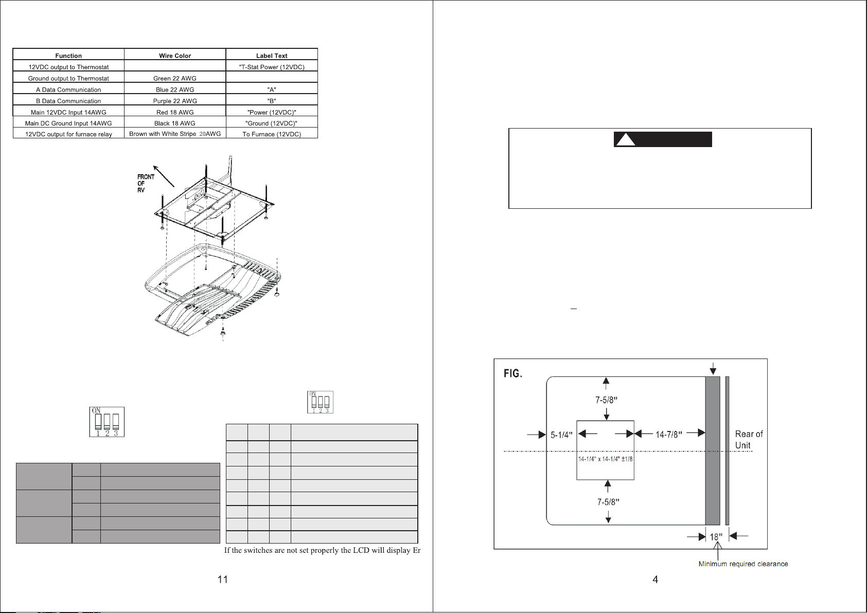
MAIN RELAY KIT WIRING
Red wit h Whi te St ri pe 22 AWG
COM
FIG. 7
C. POST LOC ATION SELECTI ON:
1. Che ck for obstru ctions in t he area where a ir condit ioner / heat pu mp will be
inst alled. A minimu m clearance o f 18" is requir ed for the re ar section of t he air
cond itioner / hea t pump to any o ther roof mou nted obje ct.
2. The roof mu st be capab le of support ing 100 Ibs w hile the RV is in mot ion. Normal ly,
a 200 Ib . static load d esign wil l meet this req uiremen t.
3. ROOF PREPARATION
There may b e electric al wiring be tween the roof and
the ceili ng. Discon nect 120 vol t AC power cord and th e
positiv e (+) 12 volt DC t erminal at t he supply battery.
Failure t o follow thi s instruction may create a shock
hazard ca using deat h or severe pe rsonal injury.
A. EXISTI NG ROOF VENT R EMOVAL:
1.Un screw and rem ove the roo f vent.
2. Rem ove all caulk ing compo und around op ening.
3. Sea l all screw hol es and seam s where the roo f gasket wi ll be located . Use a good
grad e of all weathe r sealant .
B. NEW OPEN ING:
1.A 14- 1/4" x 14-1/4 "+1/8" op ening must be c ut throug h the roof and ce iling of th e RV.
It is re commended t his openi ng be located b etween ro of framewor k.
2. Mar k a 14-1/4" x 14- 1/4" squa re on the roof an d careful ly cut the open ing.
3. Usi ng the roof ope ning as a gui de, cut the mat ching hol e in the ceilin g. See FIG.3.
WARNING
!
THERMOS TAT DIP SWITCH SE TTINGS:
Dip swi tc h
As shown ALL OFF
Heat St rip f un cti on disa ble
Dip Swi tch 1
Dip Swi tch 2
Dip Swi tch 3
Default S et ting is 1 OFF, 2 OFF, 3 ON
Off
Heat St rip f un cti on enab le
On
Heat Pu mp fu nc tio n disab le
Off
Heat Pu mp fu nc tio n enabl e
On
Off
Furna ce fu nc tio n disab le
On
Furna ce fu nc tio n enabl e
SW1 SW2 SW 3
OFF OFF OFF
ON
OFF OFF
OFF OF F
ON
OFF OFF
ON
ON O N
OFF
ONON
OFF ON
ON
ONONOFF
ON
Dip s witch
.3
Mod e Cycle
FAN - COO L
FAN - COO L - HEAT STRIP
FAN - COO L - HEAT PUMP
FAN - COO L - FURNA CE
Con figur ation n ot poss ible
FAN - COO L - HEAT PUMP - FUR NACE
FAN - COO L - HEAT STRIP - FU RNACE
Con figur ation n ot poss ible
Page 6
C. OPENIN G PREPARATION:
1. If th e opening exc eeds 14-3 /8" x 14-3/8" , it will be ne cessary to in stall space rs.
2. If th e opening is le ss than 14- 1/8" x 14-1/8 ", it must be e nlarged.
3. Rou te a 12/3 Rmoex t ype suppl y line from the c ircuit br eaker box to th e Front of
the ro of opening.
a. The power s upply mus t be on a separat e 20 amp Time De lay Fuse or HAC R
Circ uit Breaker.
b. Wir ing must comp ly with all N ational, St ate and Loc al wiring cod es.
c. Mak e sure at least 1 5" of wire ex tend into the r oof openi ng to ensure ea sy
conn ections.
4. The ope ni ng must be fr amed to provi de adequa te support an d prevent a ir from
bein g drawn from th e roof cavi ty. Lum ber 3/4" th ick or more and l ong enoug h to
brid ge the openin g must be use d. Remember t o provide a n entrance ho le in the
fron t of the openin g for 110v, 12 v, an d thermosta t wires. See FI G.4.
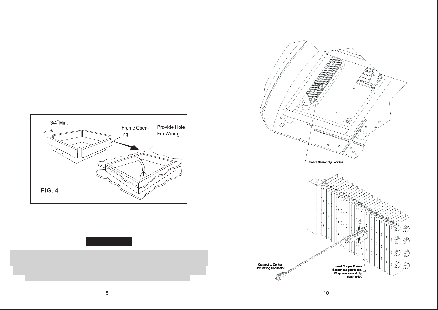
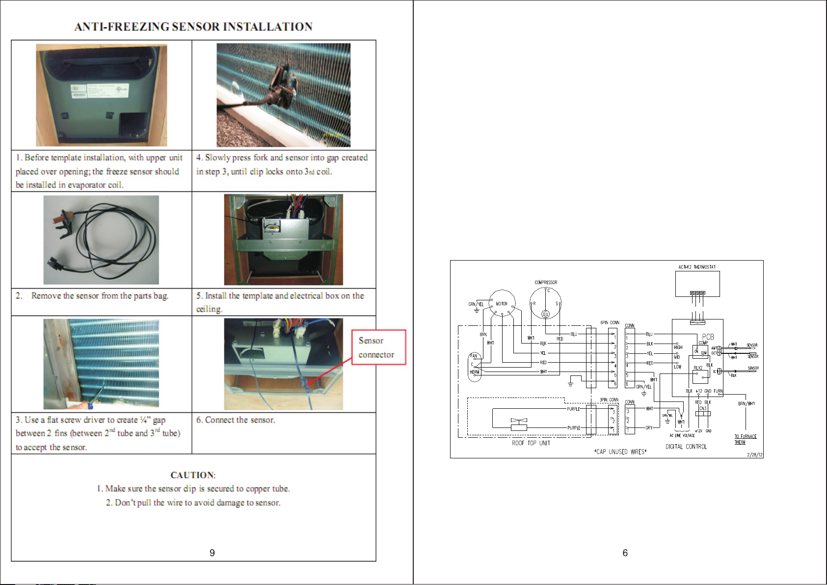
ALTERNATIVE FREEZE SENSOR INSTALL ATI ON
Chec k Upper Unit to s ee if freez e sensor clip i s preinst alled in evap orator fi ns. If so,
inse rt the copper s ensor fro m the Ducted Ce iling kit i nto the clip as s how below.
5. The 14-1/ 4" x14-1/ 4"(+1/8) ro of openin g is part of the re turn air du ct and must be
fini shed in accor dance wit h NFPA sta ndard 501 C, Standard f or Recrea tional
Vehic les, Sectio n 2-7.
CAUTION
It is the res ponsibil ity of the installer of this system to ensure structural
integri ty of the RV roof. Never create a low spot on th e roof where w ater
will coll ect. Water standing around the air condi tioner/h eat pump may
leak into t he interio r causing damage to the product and RV
Page 7
AIR RETUR N GRILL INSTALLATION (ACR G15)
The Air R eturn Grill i s designe d for applica tion in sys tems that uti lize fiel d fabricate d (OEM
supp lied)air du cting. The duct ing must be r outed throu gh the ceil ing cavity (b etween the
inte rior ceilin g and roof) . Ducting spe cificat ions are give n in the sect ion labeled S upply
Duct ing and Regis ters.
INSTALLATION REQUIREMENTS
(ROOF THI CKNESS MUS T BE AT LEAST 2.5" )
1. The ACRG mus t be instal led under the r oof openi ng. Th e ACRG bolts t o the
unde rside of the ro of unit. Co mpression o f the frame d ceiling cav ity between t he roof
unit a nd the ACRG is wha t holds bot h component s in place.
2. Cei ling cavity d epth (the m easuremen t from the ce iling to the ro of): 5.5" - Max imum,
2.5" - M inimum
3. The 115 VAC service for t he air cond itioner / hea t pump must b e routed into t he ACRG
(ref er to Fig.5 A & B below ). 12VDC sh ould be route d to the digi tal control b ox. If a LP
furn ace is being us ed, a contr ol wire must be c onnecte d from the furn ace to the digi tal
cont rol box for pro per opera tion.
FIGU RE 5A WIRING DIA GRAM FOR HE AT PUMP
COM
12VAB
BLU
GRN
PURPLE
RED/WH T
COM
12VAB
4WAY VALVE
Page 8

FIGU RE 5B WIRING DI AGRAM FOR AI R CONDITION ER ONLY
RED/WH T
4.Th e ACRG has a 6pin, t wo 3 pin & two 2 pi n connector s extendi ng from the fro nt of
the re lay kit. These co nnectors ma te with the a ir conditio ner / heat pump . When
maki ng this conne ction, ve rify that the p lugs are pr operly alig ned and hav e sn apped
toge ther secure ly.
5.Pr ovided with t he ACRG,is a d ivider plat e which is us ed to separat e the warm re turn
air fr om the cold sup ply air. If th e roof thickn ess is grea ter than 2.5" , you MUST use the
addi tional divi der provi ded.
SUPPLY DUCTING AND REG ISTERS
A. Duc ting
1. The field f abricat ed supply duc ting must a ttach to both s ides of the ACRG . A
mini mum of two duct s are requi red, with one d uct attac he d to each sid e of the plenum .
2. Eac h duct must hav e a minimum h eight of 1-1/ 2". Maxim um height can not exceed 4" .
Tot al free are a inside each d uct must be no le ss than 10 sq uare inches .
NOTE : To decrease res trictio n and increas e airflow, t he ducting sh ould make a s fe w bends
and tu rns as possib le. When co rners or turn s are require d, we recom mend that you
add ra dii to the corn ers to keep a irflow at a air flow and syst em perfor mance.
3. All fi eld fabrica ted air sup ply ducting m ust be insu lated to avoi d condens ation and
prev ent cooling / h eating lo ss.
B. Reg isters
Air re gisters sho uld have a mi nimum disch arge area o f 48 square inc hes per sys tem, or 24
squa re inches per d uct run.
War nings abo ut wiring:
1. U.L . approval re quires th e power suppl y to be coppe r conductor s with mini mu m #12AWG .
2. To prevent vo ltage dro ps greater th an 10% duri ng starting l oads, adh ere to the foll owing
guid eline: For le ngths gre ater than 50 fe et, use #10 AWG.
TEMPLATE MOUNTING
Fram e Mounting
1. Pla ce the air cond itioner / h eat pump over t he roof ope ning.
2. Ins tall freeze s ensor(s ee below Fig. 6). Some ai r condition ers / heat pump s may conta in
a prei nstalled, p lastic, r etaining cl ip for the fr eeze sensor. I f the clip is pre sent in the
evap orator coil , please us e this clip and d iscard th e clip that cam e with the free ze sensor.
Inse rt the freeze s ensor int o the plastic c lip and ens ure the freez e sensor is sec ured
prop erly in the cli p. Connec t the freeze se nsor harn ess to the rela y box mating ha rness.
3. Pos ition the mou nt frame in to the ceilin g opening . See Figure 7.
4. Usi ng the four bol ts provid ed, hold up the m ount temp late to the cei ling. The four mo unting
bolt s are to be inser ted up thro ugh the botto m of the moun t te mplate an d into the bott om
of the a ir conditio ner / heat pu mp. Tighten al l 4 boles equ ally to compr ess gasket 33 -35
inch p ounds. When m oving the a ir conditio ner / heat pu mp be sure not to d amage the
gask et by sliding i t across th e roof. If the ga sket is damag ed and need s replaced, p lease
cont act ASA Electro nics and pu rchase an aut horized Ad vent gasket f or replac em ent.
Usin g other gaske t materia l is not recomm ended and c ould result i n warrant y de nial.
5. Ins tall divide r with foam s eal against b ase pan of up per unit. On th inner roofs , the divid er
may be t oo high, so bre ak away add itional por tion. Rem ove paper cov er on fixed d ivider,
inse rt loose divi der again st base pan and s tick to fix ed divider.
6. Cut t he insulati on to the hei ght of the divi der, cente r insulatio n on divide r before remo ving
pape r backing and a pply to div ider. Excess i nsulati on will help en sure the se al at the end
of the d ivider/fr ame.
7. Con nect 115VAC and 12VDC wir es, Freez e Sensor Thermi stor, Heat Pum p specifi c
(Out door Coil Therm istor, Outdo or Ambient Therm istor), a nd thermost at cable acco rding
to the w iring diagr am. Insta ll the cover ov er the elec trical box us ing the small s crew
prov ided as shown i n Figure 7.
8. Sea l all seams bet ween outp ut airside an d return ai rside with in sulatio n and foil tape .
 Loading...