

Page 1

High Power Wireless – N
USB Adapter
Manual
Model # AWN-11N-USB
Page 2

Table of Contents
1 USING THIS DOCUMENT........................................................................ 3
2 INTRODUCTION......................................................................................3
3 SYSTEM REQUIREMENTS.....................................................................3
4 Driver Installation and Uninstallation....................................................4
4.1 Driver Installation..................................................................................... 4
4.2 Driver Uninstallation ................................................................................ 8
5 Wireless LAN Manaement GUI.............................................................12
Introduction of Main Window............................................................................. 12
A. Main Menu......................................................................................... 12
B. Adapter
C. Properties
D.
Global Control Bar............................................................................. 14
5.1 S
5.2 General
5.3 Profile
5.4 A
5.5 S
5.6 S
5.7
tation Mode.......................................................................................... 15
vailable Network.................................................................................. 18
tatus Page........................................................................................... 19
tatistics Page....................................................................................... 20
Wi-Fi Protect Setup ............................................................................... 21
List Area............................................................................... 13
Area.................................................................................. 14
Page ........................................................................................ 16
Page........................................................................................... 17
6 Access Point Mode...............................................................................22
6.1 General Page ........................................................................................ 22
6.2 Advanced Page..................................................................................... 24
6.3 S
6.4 ICS
tatistics Page....................................................................................... 24
Page...............................................................................................26
Page 3

1 USING THIS DOCUMENT
This document provides detailed user guidelines for Wireless LAN USB Adapter
operation and setting-up. Though every effort has been made to ensure that this
document is up-todate and accurate, more information may have become available
subsequent to the production of this guide.
2 INTRODUCTION
Thank you for purchasing Wireless LAN USB Adapter.Wireless LAN USB Adapter is a
perfect combination of both performance and cost-effective product introduced. It is
sincerely hoped that you can enjoy the wireless world through this solidly profiled
wireless adapter.
It provides a full solution of all the IEEE 802.11 b/g/n protocols, that pass the WiFi
tests and are compatible with all the wireless products with WiFi logo. If you have a
Wireless LAN USB Adapter on hand, it means you can connect to the wireless world
without any difficulty.
It also provides all the data rates in the IEEE 802.11 b/g/n standards, with both short
and long preambles to ensure the compatibility of legacy wireless products and new
ones, saving the panic works for end users to find compatible products.
Since the security issue has become one of the most important one in the wireless
society, it provides you with the full security coverage from the 64/128bits WEP
encryptions, second generation WPA-PSK encryption, to the most advanced
WPA2-AES encryption. WPA2 is the latest security standard currently approved by
WiFi standards.
Saving mode, Ad hoc wireless LAN, Wake on LAN (WOL) and other exciting features
are also included in this Wireless LAN USB Adapter. This user manual will guide you
through these exciting features in the following chapters and we is believed that you
will be greatly satisfied with its performance and ease of use.
3 SYSTEM REQUIREMENTS
Windows System : Windows 98SE, Me, 2000, XP 32/64 bit, Vista 32/64 bit, WIN7
32/64 bit. PCs must have a device driver installed. It allows you to communicate with
WLAN USB Adapter.
Page 4
4 Driver Installation and Uninstallation
Warning! Do not cover or block the airflow to the adapter. The adapter will reach a
high temperature during use.
4.1 Driver Installation
Before you proceed with the installation, please notice the following descriptions.
Notes1:
The following installation was operated under Windows 7.
(Procedures are similar for Windows 98SE/Me/XP/2000/vista.)
Notes2:
If you have installed the WLAN USB driver & utility before, please uninstall the old
version first.
Do not plug the wireless LAN USB adapter into your computer USB port before
installing the software program
Insert the software program CD , then auto installation window pops up on
following:
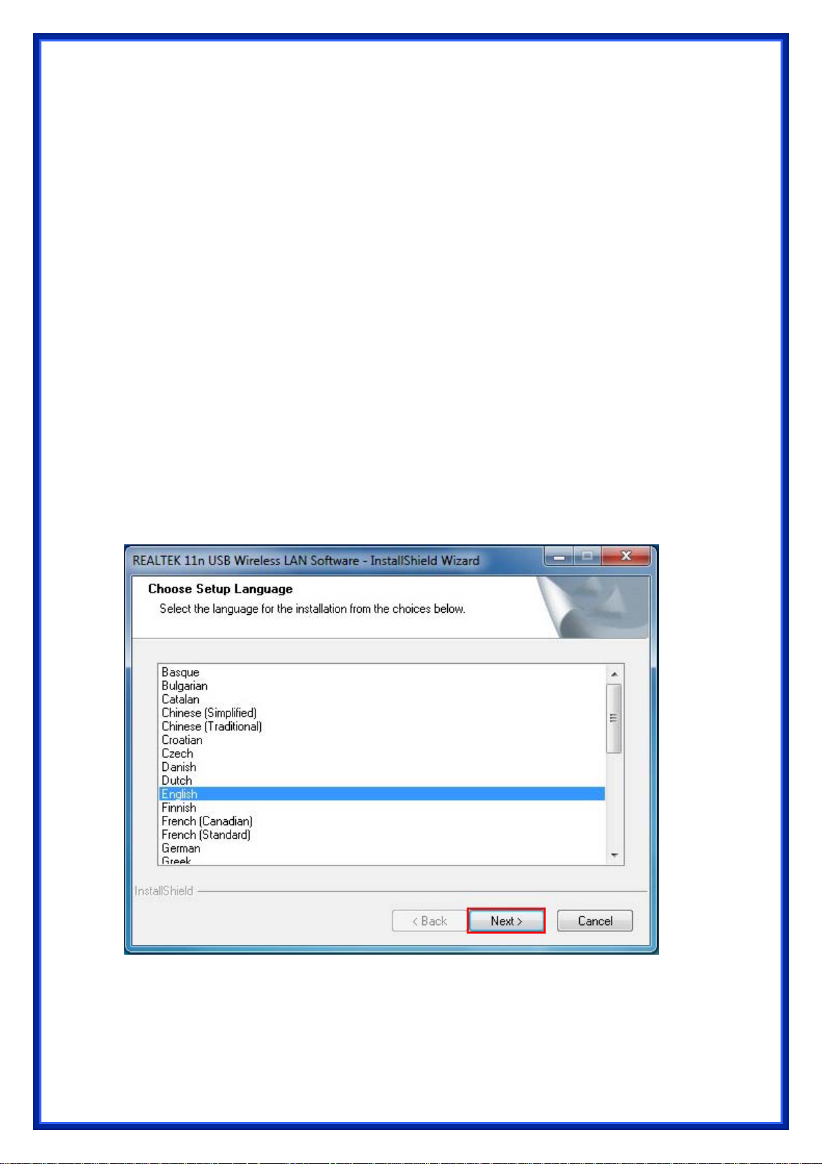
Step1: While the following screen pop s out, click Driver Installation or browser the CD,
click setup.exe
Step 2: Choose a setup language. Click Next to process the installation.
Page 5
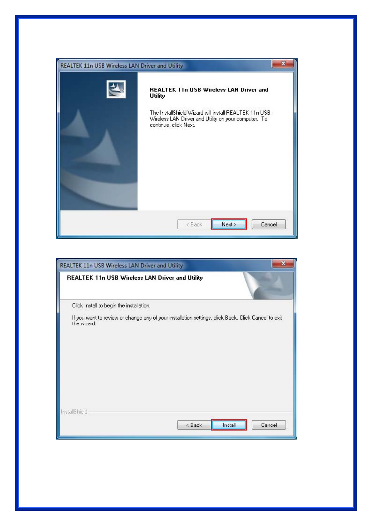
Step 3: Click Next
Step 4: Click Install
Page 6
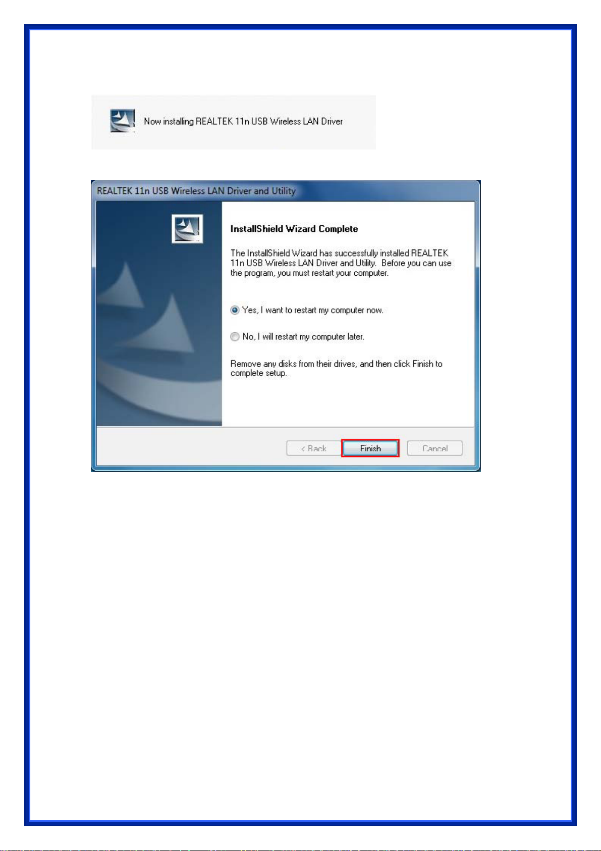
The system starts software installation of the WLAN USB adapter.
Step 5: Click Finish to complete the installation.
Page 7
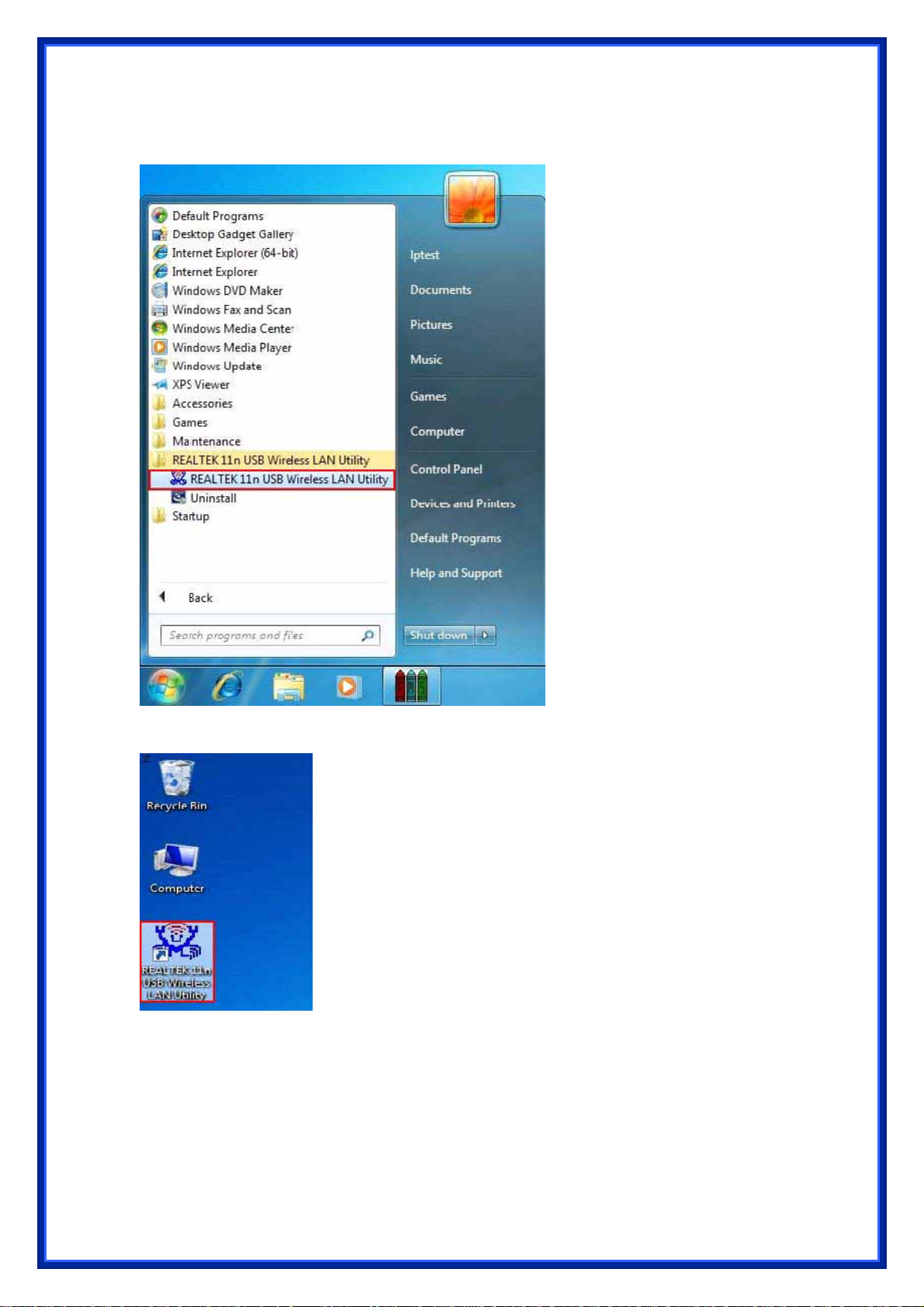
After click Finish to complete the installation , under Windows7 <ALL Programs>
menu , REALTEK 11n USB wireless LAN Utility program installed.
Realtek Utility shortcut on the desktop.
Insert the wireless LAN USB adapter into your computer USB port , the computer
detected and active the wireless LAN USB adapter automatically.
Page 8
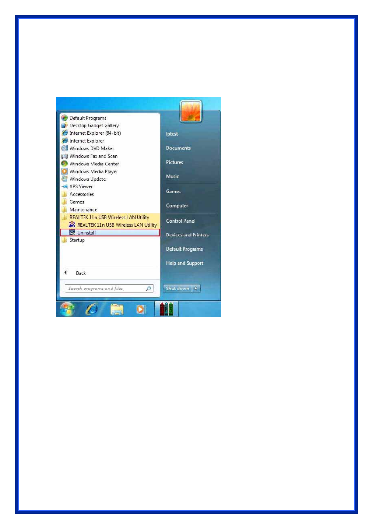
4.2 Driver Uninstallation
Step 1:
Uninstall the WLAN USB Adapter Driver from "Start">"All Programs" >"REALTEK 11n
USB Wireless LAN Utility">Click "Uninstall" to remove Wireless LAN USB Adapter
driver.
Page 9

Open Control Panel and click Programs.
Click Uninstall a program
Page 10

Select REALTEK Wireless LAN Driver and Utility Click Uninstall
Step2: Click Yes.
Page 11

Step 3: Click Finish to complete the uninstallation.And restart computer.
Page 12

5 Wireless LAN Manaement GUI
Introduction of Main Window
A. Main Menu
1. Refresh(R)
When clicking the refresh menu, you can update and re-enumerate the contents
of adapter list area.
2. Mode(M)
Wireless configuration is quickly switched to be either [Station] or [Access Point].
Page 13

3. About (A)
Click the "About" to show the about dialog. The application version and license
information are shown in the about dialog.
B. Adapter List Area
All connected adapters on this system with multiple adapter installations are
displayed in this area. It is easy for users to change the selected adapter by one click.
The contents of properties area are dependant on wireless configuration that the
selected adapter is set up. If only single adapter is installed on the system, only one
adapter is always selected.
Page 14

C. Properties Area
The contents of this area are dependent on current wireless configuration. The
current configuration is determined on previous explanation of submenu "Mode". The
more detailed contents are described in the following wireless configuration sections
for both Station and AP mode.
D. Global Control Bar
Each control item on this bar affects the adapter or management GUI directly.
Show Tray Icon
Checking "Show Tray Icon" and clicking “Close” button, the management GUI will
be minimized and stay on the tray icon located at the right bottom
If not, management GUI will shut down while clicking
condition.
Client mode utility running but no WLAN Adapter plugged.
"Close" button with unchecked
corner of Windows.
Page 15

Client mode utility running and WLAN Adapter scan available network.
Client mode utility running and WLAN Adapter can not scan any AP.
Radio Off
Turn off the radio to save power.While the radio is off, the links with other wireless
network nodes are disconnected. User should be aware that while the
configuration is in AP mode. The radio off will cause the sub network
AP to be disconnected with internet/intranet.
wireless
belonging to the
Disable Adapter
Stop wireless USB device.
Close
Whether to check or uncheck "Show Tray Icon" is to shutdown or hide the
management GUI.
5.1 Station Mode
The following explanations focus on the properties area.
Page 16

Infrastructure and Ad-Hoc
With both Infrastructure and Ad-Hoc types, the properties should look like the
picture above. Six property pages present different information of current wireless
network status.Please read the following explanations before you reviewing these
pages, it could help you to well understand the wireless environment around the
system. It is easy to use to switch property pages just by clicking left button of mouse
on the title of each page. The following six sections describe detailed information of
each page.
5.2 General Page
This page represents the general information of this adapter.
1. Status : The status of station connection to AP.
2. Speed : Current transition speed in Mbps (Mega-Bits-Per-Second).
3. Type : Current wireless LAN configuration type.
4. Encryption : Current encryption mode used.
5. SSID : Name of wireless network.
6. Signal Strength :
The average signal quality of packets received from wireless network.
We recommend connecting AP with over 70% signal strength.
7. Throughput Diagram :
Current throughput, including transmission (Tx) and total traffic (Total).
Page 17

8. Network Address
z Mac Address: six two-digital number of this Wireless LAN USB adapter
z IP Address: assigned network address by DHCP server or self-definition in four
three-digital number format.
z Subnet Mask: the only valid value is 2555.255.255.0
z Gateway: It comes from connected AP. Your system can not connect internet
with this field empty.
5.3 Profile Page
This page provides profiles management such as add, remove, edit and duplicate
just by pressing the respected button.
Available Profile(s)
The list box shows all the created profiles.
1. Add : Add a new profile for AP or IBSS (Ad-Hoc mode).
2. Remove : Remove the selected profile.
3. Edit : Edit contents of selected profile.
4. Duplicate : Make copy of selected profile.
5. Set Default : Set the selected profile as default selection.
Page 18

5.4 Available Network
This page presents all BSS, including AP and IBSS, around this system. You can
pick any one of these network connections.
1. Refresh : Rescan network connection around this system.
2. Add to Profile :
Create profile for selected network connection and add it to to profile list.
Page 19

5.5 Status Page
z NDIS Driver Version: Driver version
z Short Radio Header: No
z Encryption: Current encryption mode.
z Authenticate: Authentication state
z Channel Set: Selected channel plan currently.
z MAC Address: MAC address of this adapter.
z Data Rate: Wireless LAN transition speed
z Channel(Frequency): Current channel number
z Status: Wireless network status
z SSID: name of connecting AP
z Network Type: Indicate current network configuration type
z Power Save Mode: Current setting power save mode
z Associated AP MAC: MAC address of connecting AP
z Associated AP IP: IP address of connecting AP
z Up Time: Total connection time
Page 20

5.6 Statistics Page
You could watch the Tx/Rx status of current wireless connection. This page
shows a statistic analysis of packet transition.
Page 21

5.7 Wi-Fi Protect Setup
Page 22

6 Access Point Mode
6.1 General Page
This page provides general information of this AP, including name, MAC address
and list of joined stations.
1. SSID : The name of this AP.
2. BSSID : Six two-digital numbers of the MAC address of this AP.
3. Association Table : It is the list of joined stations to this AP.
4. AID (Association ID) :
The AID field is a value assigned by an AP during association that represents
16-bit ID of a station. It is a unique value assigned by AP.
5. MAC address :
It is the six two-digit numbers that assemble the MAC address of respected joined
station.
6. Life Time :
It is the timer that counts down from 10 minutes whenever the AP connects the
station successfully. If an STA associated to SW AP does not have any interaction
with the AP in 10 minutes, it will be disassociated from the Infra-structure BSS.
7. Config : A dialog of this AP is shown for configuration modification.
Page 23

a. Network Name (SSID) :
Name of the AP searchable by other wireless nodes. The length of SSID should
be shorter than 32 characters.
b. Channel : Select the wireless channel within current channel plan.
c. Network Authentication & Data Encryption :
z Open System :
It is combined with data encryption type to be WEP or to be disabled. Disabled:
you decide to open this AP to every one without network authentication. WEP:
you decide to setup the basic data encryption with a definednetwork key.
z Shared Key + WEP :
You decide to apply both authentication and data encryption to prevent
unauthouized login.
z WPA-PSK + TKIP & WPA2-PSK + TKIP :
The most advanced authentication and data encryption that provide the best
security protection.
d. ASCII / PASSPHRASE :
z ASCII :
You should provide either 5 or 13 ASCII characters on Network key edit box.
z PASSPHRASE : You could input words on Network
z Key edit box :
64 bits: The generated pass key is 64-bit to be complied with data packets. 128
bits: The generated pass key is 128-bit to be complied with data
z Hexadecimal :
While both ASCII and PASSPHRASE are not checked, you should input
packets.
Page 24

hexadecimal number in the network key box. For example, 10 digits hex number
for 64-bit WEP or 26 digits hex number for 128-bit WEP.
e. Ke y index (advanced) (1 ~4) :
At most four key index to represent the opposite network key.
6.2 Advanced Page
Users could setup the advanced characteristics of network packet for
transmission on this page.
1. Beacon Interval :
This filed indicates the interval between each beacon that this AP sends o ut in unit
of TU (1024 micro-seconds).
2. DTIM Period :
The DTIM Period field is the number of Beacon intervals between successive
DTIMs.
3. Preamble Mode :
z Long: higher quality but with lower performance than preamble short mode.
z Short: Normal quality but with higher performance then preamble long mode.
z Auto: select the proper preamble mode by current signal frame information.
6.3 Statistics Page
The Tx/Rx status of current wireless connection is shown. A statistic analysis of
packet transition is listed.
Page 25

Page 26

6.4 ICS Page
1. ConnName :
List all network connections to this system.
You can pick up one from the listed item(s) whose network domain you would
want to connect to.
2. Select : Make the desired network connection to public network.
3. ICS :
Internet Connection Sharing.
It enables this AP to create the domain to share this internet/intranet network
connection.
4. Firewall :
Any of a number of security schemes that prevents unauthorized users from
gaining access to a computer network, or that monitors transfers of information to
and from the network.
5. Apply : Execute the current settings.
 Loading...