

Page 1

To access this page, click Configuration > Services > DynDNS.
Figure 3.33 Configuration > Services > DynDNS
Item Description
Hostname The third order domain registered on the www.dyndns.org server.
Username Username for logging into the DynDNS server.
Password Password for logging into the DynDNS server.
IP Mode Specifies a DynDNS se rvice other than the www.dyndns.org. Possible
other services: www.spdns.de, www.dnsdynamic.org, www.noip.com.
Enter the update server service information in this field. If you leave
this field blank, the default server members.dyndns.org will be used.
Server Specifies the version of IP pr otocol:
IPv4 - IPv4 protocol is used only (default).
IPv6 - IPv6 protocol is used only.
IPv4/IPv6 - IPv4 and IPv6 dual stack is enabled.
Example: DynDNS client configuration with the domain company.dyndns.org:
Figure 3.34 DynDNS Configuration Example
WISE-6610 Series User Manual 45
Page 2

3.4.8.2 HTTP
To access this page, click Configuration > Services > HTTP.
Item Description
Enable HTTP service Click the check box to set up Ethernet encapsulation (remote access)
Enable HTTPS
service
Session Timeout Enter the variable in minutes to define the timeout period for the
Apply Click Apply to save the values.
3.4.8.3 NTP
The NTP configuration form allows you to configure the NTP client. To open the NTP
page, click NTP in the Configuration section of the main menu. NTP (Network Time
Protocol) allows you to periodically set the internal clock of the device. The time is set
from servers that provide the exact time to network devices. IPv6 Time Servers are
supported.
If you mark the Enable local NTP service check box, then the device acts as a
If you mark the Synchronize clock with NTP server check box, then the device
To access this page, click Configuration > Services > NTP.
Figure 3.35 Configuration > Services > HTTP
through HTTP function.
Click the check box to set up Ethernet encapsulation over HTTPS.
session.
NTP server for other devices in the local network (LAN).
acts as a NTP client. This means that the device automatically adjusts the
internal clock every 24 hours.
Figure 3.36 Configuration > Services > NTP
Item Description
Primary NTP Server IPv4 address, IPv6 address or domain name of primary NTP server.
Secondary NTP
Server
Timezone Specifies the time zone where you installed the device.
Daylight Saving Time Activates/deactivates the DST shift.
IPv4 address, IPv6 address or domain name of secondary NTP
server.
No - The time shift is inactive.
Yes - The time shift is active.
46 WISE-6610 Series User Manual
Page 3
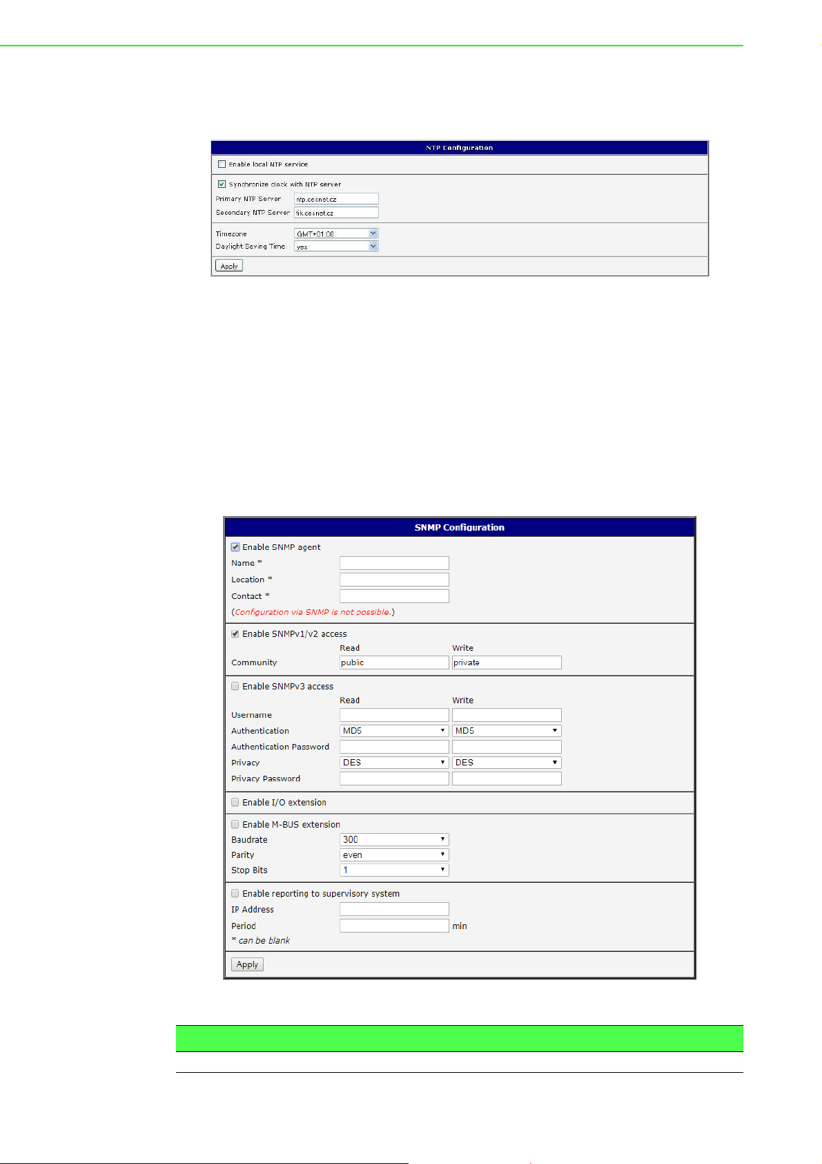
The figure below displays an example of a NTP configuration with the primary server
set to ntp.cesnet.cz and the secondary server set to tik.cesnet.cz and with the
automatic change for daylight saving time enabled.
3.4.8.4 SNMP
The SNMP page allows you to configure the SNMP v1/v2 or v3 agent which sends
information about the device (and its expansion ports) to a management station. To
open the SNMP page, click SNMP in the Configuration section of the main menu.
SNMP (Simple Network Management Protocol) provides status information about the
network elements such as devices or endpoint computers. In the version v3, the
communication is secured (encrypted). To enable the SNMP service, mark the
Enable the SNMP agent check box. Sending SNMP traps to IPv6 address is
supported.
To access this page, click Configuration > Services > SNMP.
Figure 3.37 Example of NTP Configuration
Figure 3.38 Configuration > Services > SNMP
Item Description
Name Designation of the device.
WISE-6610 Series User Manual 47
Page 4

Item Description
Location Location of where you installed the device.
Contact Person who manages the device together with information how to
contact this person.
To enable the SNMPv1/v2 function, mark the Enable SNMPv1/v2 access check box.
It is also necessary to specify a password for access to the Community SNMP agent.
The default setting is public.
You can define a different password for the Read community (read only) and the
Write community (read and write) for SNMPv1/v2. You can also define 2 SNMP users
for SNMPv3. You can define a user as read only (Read), and another as read and
write (Write). The device allows you to configure the parameters in the following table
for every user separately. The device uses the parameters for SNMP access only.
To enable the SNMPv3 function, mark the Enable SNMPv3 access check box, then
specify the following parameters:
Item Description
Username User name
Authentication Encryption algorithm on the Authentication Protocol that is used to
verify the identity of the users.
Authentication
Password
Privacy Encryption algorithm on the Privacy Protocol that is used to ensure
Privacy Password Password for encryption on the Privacy Protocol.
Password used to generate the key used for authentication.
confidentiality of data.
Activating the Enable I/O extension function allows you monitor the binary I/O inputs
on the device.
Selecting Enable M-BUS extension and entering the Baudrate, Parity and Stop Bits
lets you monitor the meter status connected to the expansion port MBUS status.
Selecting Enable reporting to supervisory system and entering the IP Address and
Period lets you send statistical information to the monitoring system, R-SeeNet.
Item Description
IP Address IPv4 or IPv6 address.
Period Period of sending statistical information (in minutes).
Each monitored value is uniquely identified using a numerical identifier OID - Object
Identifier. This identifier consists of a progression of numbers separated by a point.
The shape of each OID is determined by the identifier value of the parent element
and then this value is complemented by a point and current number. So it is obvious
48 WISE-6610 Series User Manual
Page 5
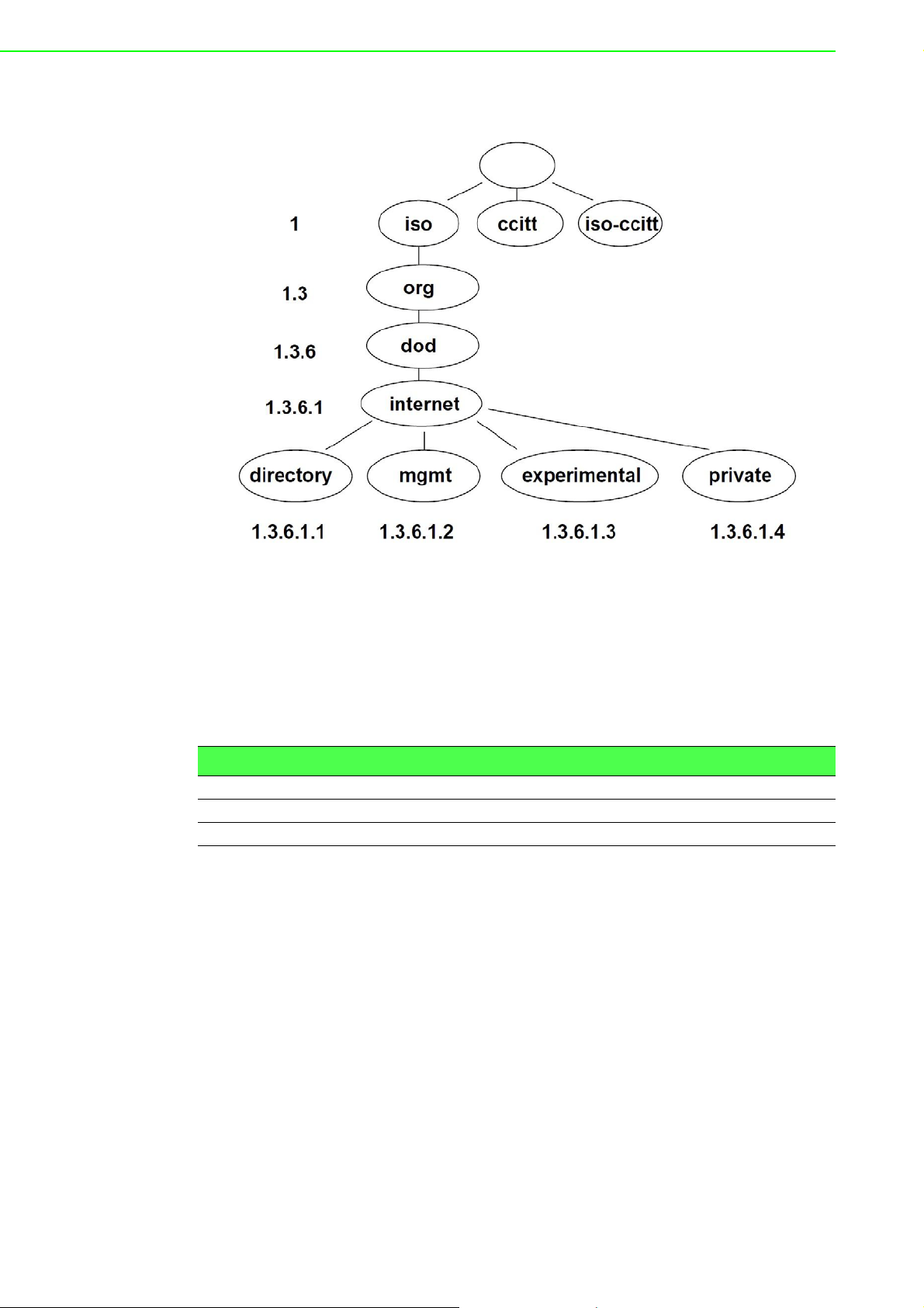
that there is a tree structure. The following figure displays the basic tree stru cture that
is used for creating the OIDs.
Figure 3.39 OID Basic Structure
The SNMP values that are specific for Conel devices create the tree starting at OID =
.1.3.6.1.4.1.30140. You interpret the OID in the following manner:
iso.org.dod.internet.private.enterprises.conel
This means that the device provides for example, information about the internal
temperature (OID 1.3.6.1.4.1.248.40.1.3.3) or about the power voltage (OID
1.3.6.1.4.1.248.40.1.3.4). For binary inputs and output, the following range of OID is
used:
OID Description
.1.3.6.1.4.1.30140.2.3.1.0 Binary input BIN0 (values 0,1)
.1.3.6.1.4.1.30140.2.3.2.0 Binary output OUT0 (values 0,1)
.1.3.6.1.4.1.30140.2.3.3.0 Binary input BIN1 (values 0,1)
WISE-6610 Series User Manual 49
Page 6
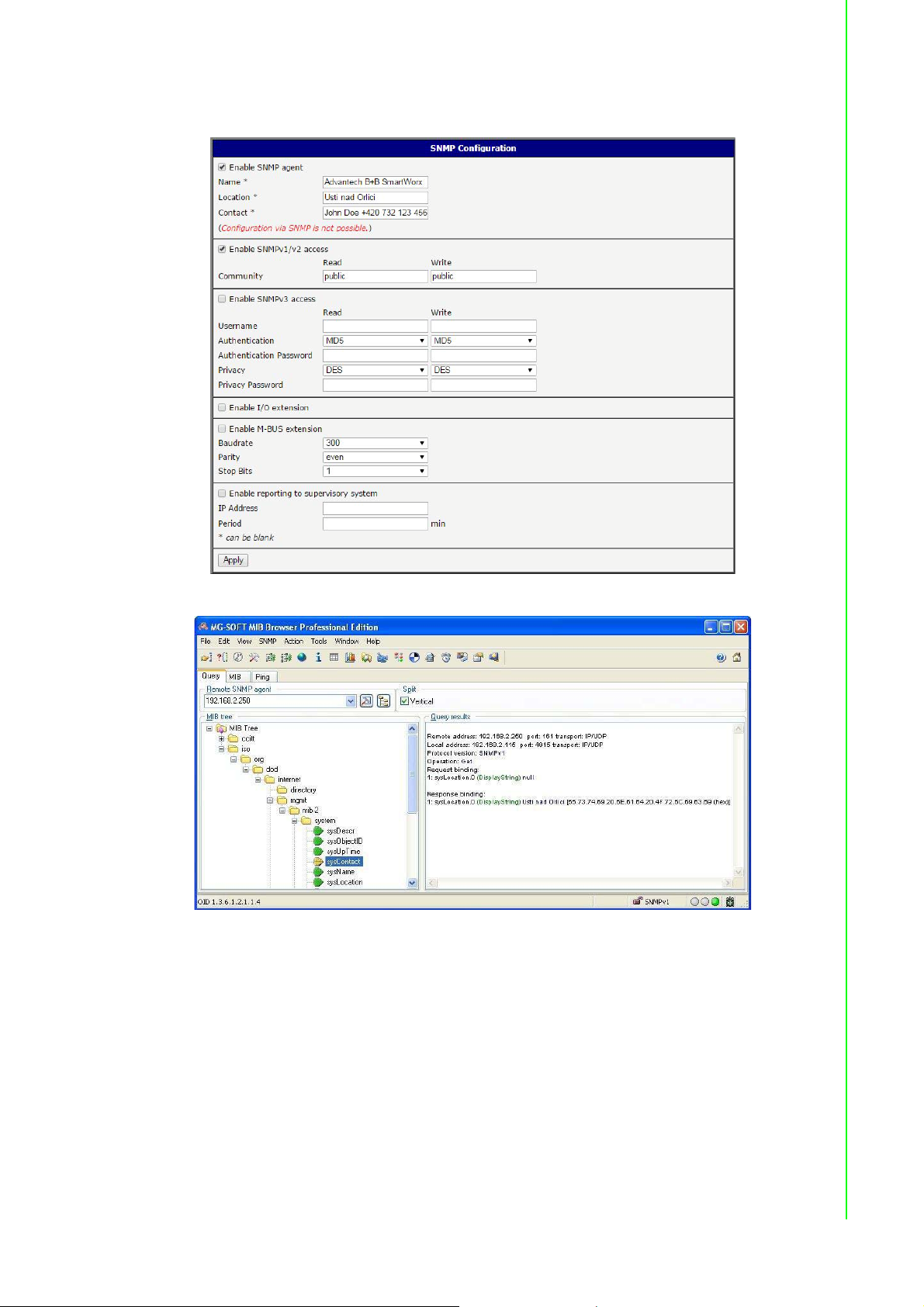
The list of available and supported OIDs and other details can be found in the
application note SNMP Object Identifier [8].
Figure 3.40 SNMP Configuration Example
Figure 3.41 MIB Browser Example
In order to access a particular device enter the IP address of the SNMP agent which
is the device, in the Remote SNMP agent field. The dialog displayed the internal
variables in the MIB tree after entering the IP address. Furthermore, you can find the
status of the internal variables by entering their OID.
50 WISE-6610 Series User Manual
Page 7

The path to the objects is:
The path to information about the device is:
3.4.8.5 SMTP
Use the SMTP form to configure the Simple Mail Transfer Protocol client (SMTP) for
sending e-mails. IPv6 e-mail servers are supported.
To access this page, click Configuration > Services > SMTP.
iso ? org ? dod ? internet ? private ? enterprises ? conel ? protocols
iso ? org ? dod ? internet ? mgmt ? mib-2 ? system
Figure 3.42 Configuration > Services > SMTP
Item Description
SMTP Server
Address
SMTP Port Port the SMTP server is listening on.
Secure Method None, SSL/TLS, or STARTTLS. Secure method has to be supported
Username Name for the e-mail account.
Password Password for the e-mail account. The password can contain the
Own Email Address Address of the sender.
IPv4 address, IPv6 address or domain name of the mail server.
by the SMTP server.
following special characters * + , - . / : = ? ! # % [ ] _ { } ~
The following special characters are not allowed: " $ & ' ( ) ; < >
The mobile service provider can block other SMTP servers, then you can only use
the SMTP server of the service provider.
Figure 3.43 SMTP Client Configuration Example
You can send e-mails from the Startup script. The Startup Script dialog is located in
Scripts in the Configuration section of the main menu. The device also allows you to
send e-mails using an SSH connection. Use the email command with the following
parameters:
-t: e-mail address of the receiver
-s: subject, enter the subject in quotation marks
-m: message, enter the subject in quotation marks
-a: attachment file
WISE-6610 Series User Manual 51
Page 8

-r: number of attempts to send e-mail (default setting: 2)
Note! Commands and parameters can be entered only in lowercase.
Example: Sending an e-mail:
The command above sends an e-mail to address john@doe.com with the subject
"System Log", body message "Attached" and attachment messages file with System
Log of the device directly from the directory /var/log/.
3.4.8.6 SSH
To access this page, click Configuration > Services > SSH.
email -t john@doe.com -s "System Log" -m "Attached" -a /var/log/messages
Item Description
Enable SSH service Click the check box to set up Ethernet encap sul ation (remote a ccess)
Session Timeout Enter the variable in minutes to define the timeout period for the
Apply Click Apply to save the values.
3.4.9 Scripts
There is possibility to create your own shell scripts executed in the specific situations.
Go to the Scripts page in the Configuration section in the menu. The menu item will
expand and there are Startup Script, Up/Down IPv4 and Up/Down IPv6 scripts you
can use - there is IPv4 and IPv6 independent dual stack. For more examples of
Scripts and possible commands see the Application Note Commands and Script s [1].
To access this page, click Configuration > Scripts.
3.4.9.1 Startup Script
Use the St artup Script window to create your own scripts which will be executed after
all of the initialization scripts are run - right after the device is turned on or rebooted.
The changes in settings will apply after pressing the Apply button.
To access this page, click Configuration > Scripts > Startup Script.
Figure 3.44 Configuration > Services > SSH
through the Secure Shell (SSH) function.
session.
Note! Any changes to the Startup Script will take effect the next time the
device is power cycled or rebooted. This can be done with the Reboot
button in the Administration section, or by SMS message.
52 WISE-6610 Series User Manual
Page 9
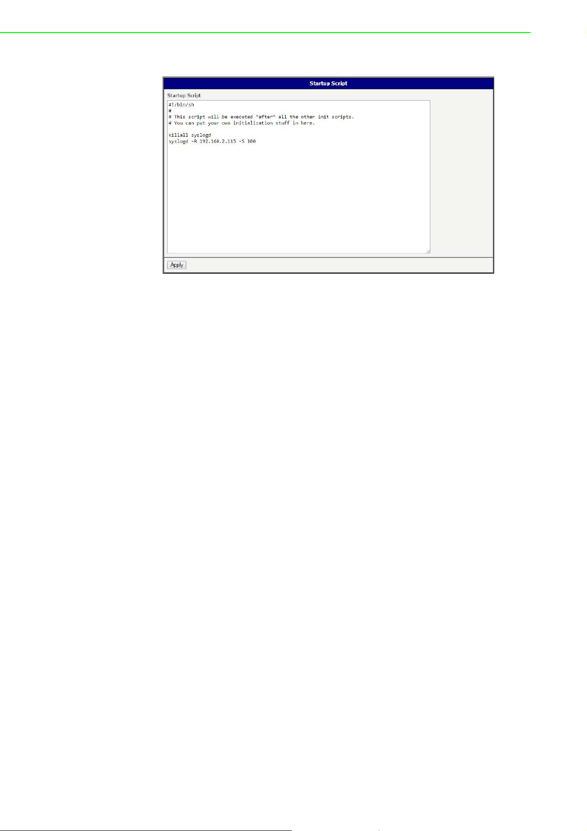
Example: Startup Script
Figure 3.45 Example of a Startup Script
When the device starts up, stop syslogd program and start syslogd with remote
logging on address 192.168.2.115 and limited to 100 entries. Add these lines to the
Startup Script:
killall syslogd
syslogd -R 192.168.2.115 -S 100
3.4.9.2 Up/Down Scripts
Use the Up/Down IPv4 and Up/Down IPv6 page to create scripts executed when the
Mobile WAN connection is established (up) or lost (down). There is independent IPv4
and IPv6 dual stack implemented in the device, so there is independent IPv4 and
IPv6 Up/Down script. IPv4 Up/Down Script runs only on the IPv4 WAN connection
established/lost, IPv6 Up/Down Script runs only on the IPv6 WAN connection
established/lost. Any scripts entered into the Up Script window will run after a WAN
connection is established. Script commands entered into the Down Script window will
run when the WAN connection is lost.
The changes in settings will apply after pressing the Apply button. Also you need to
reboot the device to make Up/Down Script work.
To access this page, click Configuration > Scripts > Up/Down IPv4 or Up/Down
IPv6.
WISE-6610 Series User Manual 53
Page 10
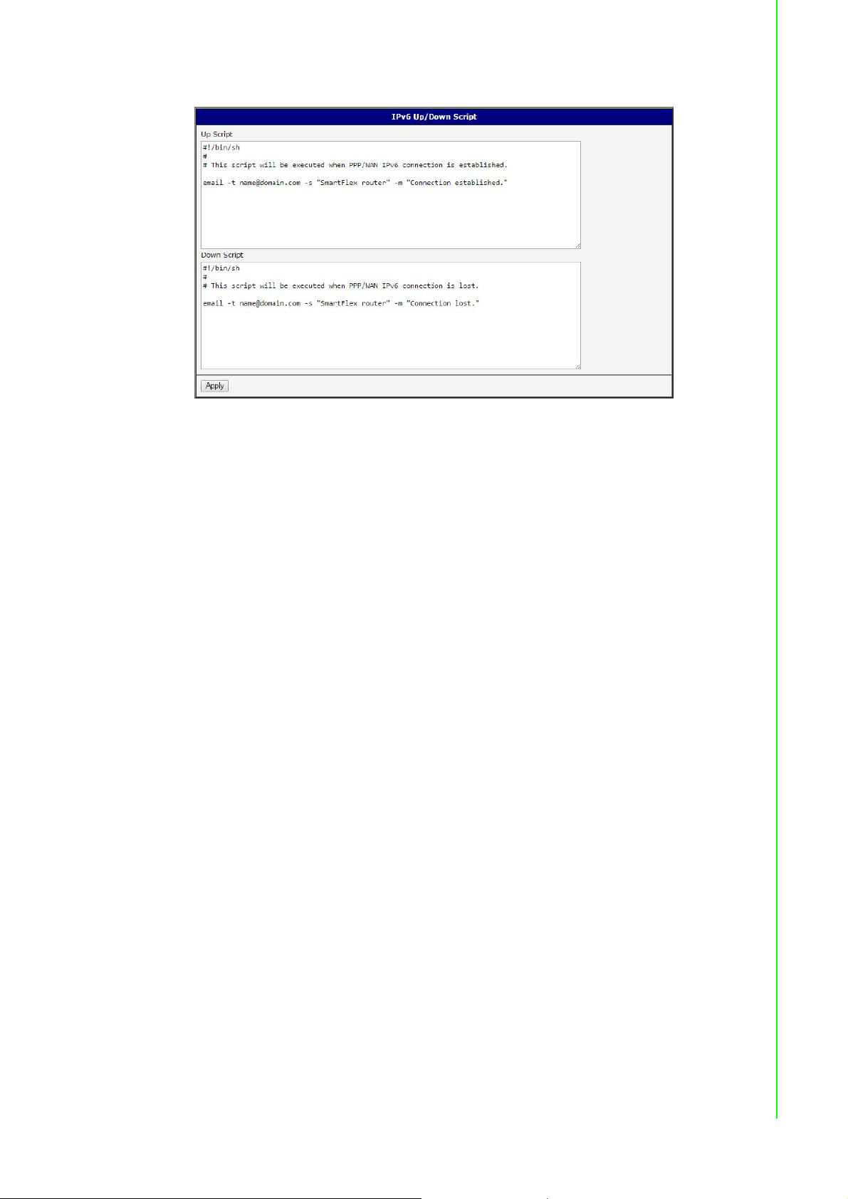
Example: IPv6 Up/Down Script
Figure 3.46 Example of IPv6 Up/Down Script
After establishing or losing an IPv6 WAN connection (connection to mobile network),
the device sends an email with information about the connection state. It is
necessary to configure SMTP before.
Add this line to the Up Script field:
email -t name@domain.com -s "Router" -m "Connection up."
Add this line to the Down Script field:
email -t name@domain.com -s "Router" -m "Connection down."
3.4.10 Automatic Update
Use the Automatic Update menu to configure the automatic update settings. The
device can be configured to automatically check for firmware and configuration
updates from a HTTP(S) or FTP(S) server. IPv6 sites/servers are supported. Used
protocol is specified by an address in Base URL field: HTTP, HTTPS, FTP or FTPS.
To prevent possible unwanted manipulation of the files, the device verifies that the
downloaded file is in the tar.gz format. At first, the format of the downloaded file is
checked. Then the type of architecture and each file in the archive (tar.gz file) is
checked.
If the Enable automatic update of configuration option is selected, the device will
check if there is a configuration file on the remote server, and if the configuration in
the file is different than its current configuration, it will update its configuration to the
new settings and reboot.
If the Enable automatic update of firmware option is checked, the device will look for
a new firmware file and update its firmware if necessary.
54 WISE-6610 Series User Manual
Page 11

To access this page, click Configuration > Automatic Update.
Figure 3.47 Configuration > Automatic Update
Item Description
Base URL Base URL, IPv4 or IPv6 address from which the configuration file will
be downloaded. This option also sp ecifies the communication protocol
(HTTP, HTTPS, FTP or FTPS), see examples below.
Unit ID Name of configuration (name of the file without extension). If the Unit
ID is not filled, the MAC address of the device is used as the filename
(the delimiter colon is used instead of a dot.)
Update Hour Use this item to set the hour (range 1-24) when the automatic update
will be performed every day. If the time is not specified, automatic
update is performed five minutes after turning on the device and then
every 24 hours. If the detected configuration file is differ ent from the
running one, it is downloaded and the device is restarted
automatically.
The configuration file name consists of Base URL, hardware MAC address of ETH0
interface and cfg extension. Hardware MAC address and cfg extension are added to
the file name automatically and it isn't necessary to enter them. When the parameter
Unit ID is enabled, it defines the concrete configuration name which will be
downloaded to the device, and the hardware MAC address in the configuration name
will not be used.
The firmware file name consists of Base URL, type of device and bin extension. For
the proper firmware filename, see the Update Firmware page in Administration
section - it us written out there. See “Update Firmware” on page 66.
Note! It is necessary to load two files (.bin and .ver) to the HTTP/FTP server. If
only the .bin file is uploaded and the HTTP server sends the incorrect
answer of 200 OK (instead of the expected 404 Not Found) when the
device tries to download the nonexistent .ver file, then there is a risk that
the device will download the .bin file over and over again.
Note! Firmware update can cause incompatibility with the user modules. It is
recommended that you update user modules to the most recent version.
Information about the user modules and the firmware compatibility is at
the beginning of the user module's Application Note.
WISE-6610 Series User Manual 55
Page 12

Example 1: Automatic Update
In the following example the device checks for new firmware or configuration file
each day at 1:00 a.m. An example is given for the WISE-6610 Series device.
Firmware file: http://example.com/SPECTRE-v3L-LTE.bin
Configuration file:http://example.com/test.cfg
Figure 3.48 Example of Automatic Update 1
Example 2: Automatic Update Based on MAC
In the following example the device checks for new firmware or configuration each
day at 1:00 a.m. An example is given for the WISE-6610 Series device with MAC
address 00:11:22:33:44:55.
Firmware file: http://example.com/SPECTRE-v3L-LTE.bin
Configuration file: http://example.com/00.11.22.33.44.55.cfg
Figure 3.49 Example of Automatic Update 2
3.5 Customization
3.5.1 Adding a Module
You may run custom software programs in the device to enhance the features of the
device. Use the User Modules menu item to add new software modules to the device,
to remove them, or to change their configuration. Use the Browse button to select
the user module (compiled module has tgz extension). Use the Add button to add a
user module.
To access this page, click User Modules (located under Customization).
The new module appears in the list of modules on the same page. If the module
contains an index.html or index.cgi page, the module name serves as a link to this
page. The module can be deleted using the Delete button.
Updating a module is done the same way. Click the Add button and the module with
the higher (newer) version will replace the existing module.
56 WISE-6610 Series User Manual
Page 13
Programming and compiling of modules is described in the Application Note
Programming of User Modules [10].
Figure 3.50 User Modules
Item Description
MODBUS TCP2RTU Provides a conversion of MODBUS TCP/IP protocol to MDBUS RTU
protocol, which can be operated on the serial line.
Easy VPN client Provides secure connection of LAN network behind our device with
LAN network behind CISCO device.
NMAP Enables TCP and UDP scan.
Daily Reboot Enables daily reboot of the device at the specified time.
HTTP Authentication Adds the process of authentication to a server that doesn't provide
this service.
HTTP Authentication Adds support of dynamic protocols.
PIM SM Adds support of multicast routing protocol PIM-SM.
WMBUS
Concentrator
pduSMS Sends short messages (SMS) to specified number.
Pinger Allows you to manually or automatically verify the functionality of the
IS-IS Adds support of IS-IS protocol.
Enable the reception of messages from WMBUS meters and saves
contents of these messages to an XML file.
connection between two network interfaces (ping).
Note! In some cases the firmware update can cause incompatibility with
installed user modules. Some of them are dependent on the version of
the Linux kernel (for example SmsBE and PoS Configuration). It is best
to update user modules to the most recent version.
Information about the user module and the firmware compatibility is at the beginning
of the user module's Application Note.
WISE-6610 Series User Manual 57
Page 14
3.5.1.1 MQTT and LoRaWAN
To access the gateway configuration page, navigate to Customization and click User
Modules > LoRaWAN Gateway > MQTT and LoRaWAN.
Figure 3.51 User Modules > LoRaWAN Gateway > MQTT and LoRaWAN
Item Description
LoRaWAN Radio Setting
Model Name Enter the model name.
LoRaWAN Radio
Enable
Radio 0 Main
Frequency(KHz)
Radio 1 Main
Frequency(KHz)
Quick Setup Click to enter the Quick Setup menu enabling the selection of pre-
LoRaWAN Gateway Setting
LoRaWAN Gateway
Identifier
Backup Enable Click the drop-down menu to enable (default: Off) the LoRaWAN
Backup Database
Interval
LoRaWAN Network Server Setting
LoRaWAN Network
Server Enable
LoRaWAN Server
Listen Port
LoRaWAN Network
Server HTTP Port
LoRaWAN Network
Server HTTPS Port
Click the drop-down menu to enable the radio channel and
corresponding settings.
Enter the frequency setting for the interface.
Enter the frequency setting for the interface.
configured region-specific, radio frequency settings.
Displays the gateway identifier for the remote LoRa network server.
backup feature.
Set the backup frequency, setting: 5 to 60 minutes.
Click the drop-down menu to disable the LoRaWAN network server
(default: On).
Enter a variable (1 to 65535) to designate the listening port.
Enter a variable (1 to 65535) to designate the HTTP port.
Enter a variable (1 to 65535) to designate the HTTPS port.
58 WISE-6610 Series User Manual
Page 15

Item Description
LoRaWAN Web
Username
LoRaWAN Web
Password
LoRaWAN Network
Server HTTPS
Enable
Update Database Click to upload an existing server database.
Download Database Click to upload the current server database. In the ensuing screen,
Factory Reset Click to reset the current server database. In the ensuing screen, click
MQTT Broker
MQTT Broker Enable Click the drop-down menu to enable or disable local MQTT broker.
MQTT Broker Port Enter a value to specify the port of MQTT broker (default: 1883).
MQTT Bridge
MQTT Bridge Enable Click the drop-down menu to enable or disable bridging to a remote
MQTT Bridge Port Enter a value to specify the port of MQTT bridge (default: 1883).
MQTT Bridge
Address
MQTT Bridge User Enter the name of the MQTT bridge user.
MQTT Bridge
Password
MQTT Bridge Client
Identifier
Advantech Application Server Setting
Application Server
Enable
Application Server
Connect MQTT
Address
Application Server
Connect MQTT Port
MQTT User Enter an identifier used to access the remote MQTT broker.
MQTT Password Enter the password associated with the MQTT user listed previously.
Uplink Topic Enter a string identifier to describe the MQTT brok er, uplink,
Downlink Topic Enter a string identifier to describe the MQTT broker, downlink,
Save Click Save to save the values.
Restore Click Restore to restore the values.
Enter an identifier used to access the Web user interface for the
LoRaWAN network server.
Enter the corresponding password to the set LoRaWAN Web
username.
Click the drop-down menu to enable the HTTPS service (default: Off).
click Download to save the database to a local drive.
to reset the database to its factory default.
MQTT broker.
Enter a value to specify the bridge address of the MQTT bridge.
Enter the character set for the define password type.u
With MQTT and LoRa configured, pair and modify the node settings,
see Node Control.
Click the drop-down menu to enable the local Application server
(default: Off).
Enter the private network address to allow bidirectional sending and
receiving of messages.
Enter a port designation to associate with the previously defined
network address.
subscription topic.
subscription topic.
With MQTT and LoRa configured, pair and modify the node settings, see Node
Control.
3.5.1.2 Licenses
To download the LoRa license, click the Licenses on the Router menu.
WISE-6610 Series User Manual 59
Page 16

3.5.1.3 LoRaWAN Status
The LoRaWAN Status menu displays specific information pertaining to the basic and
channel settings of the LoRaWAN Gateway.
To access the page use the following guidelines:
1. From the LoRaWAN router, Customization menu, click User Modules.
2. In User Modules, click the LoRaWAN Gateway link.
3. The LoRaWAN Gateway Settings menu displays. Under Router menu, click
LoRaWAN Status.
The LoRaWAN Gateway Settings menu displays listing Basic, Channel, and
Live Up Stream status information.
Figure 3.52 User Modules > LoRaWAN Gateway > LoRaWAN Status
60 WISE-6610 Series User Manual
Page 17

3.5.1.4 LoRaWAN Server
The LoRaWan Server is a ready-to-use solution, which includes a web-based user
interface, providing the components needed to build networks.
To access this page, click User Modules > LoRaWAN Gateway > LoRaWAN
Server.
Figure 3.53 User Modules > LoRaWAN Gateway > LoRaWAN Server
WISE-6610 Series User Manual 61
Page 18

3.5.1.5 LoRaWAN Server (https)
Enable the LoRaWAN Network Server HTTPS Enable function under MQTT and
LoRaWAN to access the website through https.
To access this page, click User Modules > LoRaWAN Gateway > LoRaWAN
Server (https).
Figure 3.54 User Modules > LoRaWAN Gateway > LoRaWAN Server (https)
3.5.1.6 Advantech Application
To access this page, click User Modules > LoRaWAN Gateway > Advantech
Application. For more details, see “Changing the Raw LoRa Data Format” on
page 86.
Figure 3.55 User Modules > LoRaWAN Gateway > Advantech Application
3.5.1.7 Return to Router
The main menu is accessible through the Return to Router function. To return the
WISE-6610 Series to the main menu, click Customization > User Modules >
LoRaWAN Gateway > Return to Router.
62 WISE-6610 Series User Manual
Page 19

3.6 Administration
3.6.1 Users
Note! This configuration function is only available for users assigned the
admin role!
To assign roles and manage user accounts open the Users form in the Administration
section of the main menu. The first frame of this configuration form contains an
overview of available users. The table below describes the meaning of the buttons in
this frame.
To access this page, click Administration > Users.
Figure 3.56 Administration > Users
Item Description
Lock Locks the user account. This user is not allowed to log in to the
device, neither web interface nor SSH.
Change Password Allows you to change the password for the co rresponding user.
Delete Deletes the corresponding user account.
Warning! If you lock every account with the permission role Admin, you can not
unlock these accounts. This also means that the Users dialog is
unavailable for every user, because every admin account is locked and
the users do not have sufficient permissions.
The second block contains configuration form which allows you to add new user. All
items are described in the table below.
Item Description
Role Specifies the type of user account:
User: User with basic permissions.
Admin: User with full permissions.
Username Specifies the name of the user allowed to log in the device.
Password Specifies the password for the corresponding user.
Confirm Password Confirms the password you specified above.
Note! Ordinary users are not able to access device via Telnet, SSH or SFTP.
Read only FTP access is allowed for these users.
WISE-6610 Series User Manual 63
Page 20

3.6.2 Change Profile
In addition to the standard profile, up to three alternate device configurations or
profiles can be stored in device's non-volatile memory. You can save the current
configuration to a device profile through the Change Profile menu item. Select the
alternate profile to store the settings to and ensure that the Copy settings from
current profile to selected profile box is checked. The current settings will be stored in
the alternate profile after the Apply button is pressed. Any changes will take effect
after restarting device through the Reboot menu in the web administrator or using an
SMS message.
To access this page, click Administration > Change Profile.
Example: Using Profiles
Profiles can be used to switch between different modes of operation of the device
such as PPP connection, VPN tunnels, etc. It is then possible to switch between
these settings using the front panel binary input, an SMS message, or Web interface
of the device.
Figure 3.57 Administration > Change Profile
3.6.3 Change Password
Use the Change Password configuration form in the Administration section of the
main menu for changing your password used to log on the device. Enter the new
password in the New Password field, confirm the password using the Confirm
Password field, and press the Apply button.
To access this page, click Administration > Change Password.
Warning! The default password of the device is root for the root user. To maintain
the security of your network change the default password. You can not
enable remote access to the device for example, in NAT, until you
change the password.
Figure 3.58 Administration > Change Password
64 WISE-6610 Series User Manual
Page 21

3.6.4 Set Real Time Clock
You can set the internal clock directly using the Set Real Time Clock dialog in the
Administration section of in the main menu. You can set the Date and Time manually.
When entering the values manually use the format yyyy-mm-dd as seen in the figure
below. You can also adjust the clock using the specified NTP server. IPv4, IPv6
address or domain name is supported. After you enter the appropriate values, click
the Apply button.
To access this page, click Administration > Set Real Time Clock.
Figure 3.59 Administration > Set Real Time Clock
3.6.5 Backup Configuration
You can save the configuration of the device using the Backup Configuration
function. If you click on Backup Configuration in the Administration section of the
main menu, then the device allows you to select a directory in which the device saves
the configuration file.
3.6.6 Restore Configuration
You can restore a configuration of the device using the Restore Configuration form.
To navigate to the directory containing the configuration file (.cfg) you wish to load on
the device, use the Browse button.
To access this page, click Administration > Restore Configuration.
Figure 3.60 Administration > Restore Configuration
WISE-6610 Series User Manual 65
Page 22

3.6.7 Update Firmware
Select the Update Firmware menu item to view the current device firmware version
and load new firmware into the device. There is current firmware version and
firmware filename written out. When loading the new firmware, it has to have this
name. To load new firmware, browse to the new firmware file and press the Update
button to begin the update.
Warning! Do not turn off the device during the firmware update. The firmware
update can take up to five minutes to complete. Always use the filename
written out as Firmware Name when updating the firmware.
To access this page, click Administration > Update Firmware.
Figure 3.61 Administration > Update Firmware
During the firmware update, the device will show the following messages. The
progress is shown in the form of adding dots ('.').
After the firmware update, the device will automatically reboot.
Note! Uploading firmware intended for a different device can cause damage to
the device.
Starting with FW 5.1.0, a mechanism to prevent multiple startups of the firmware
update is included. Firmware update can cause incompatibility with the user
modules. It is recommended to update user modules to the most recent version.
Information about user module and firmware compatibility is at the beginning of the
user module's Application Note.
66 WISE-6610 Series User Manual
Page 23

3.6.8 Reboot
To reboot the device select the Reboot menu item and then press the Reboot button.
To access this page, click Administration > Reboot.
Figure 3.62 Administration > Reboot
WISE-6610 Series User Manual 67
Page 24

Chapter 4
4Configuration in
Typical Situations
Page 25

4.1 Enabling the LoRaWAN and Network Server
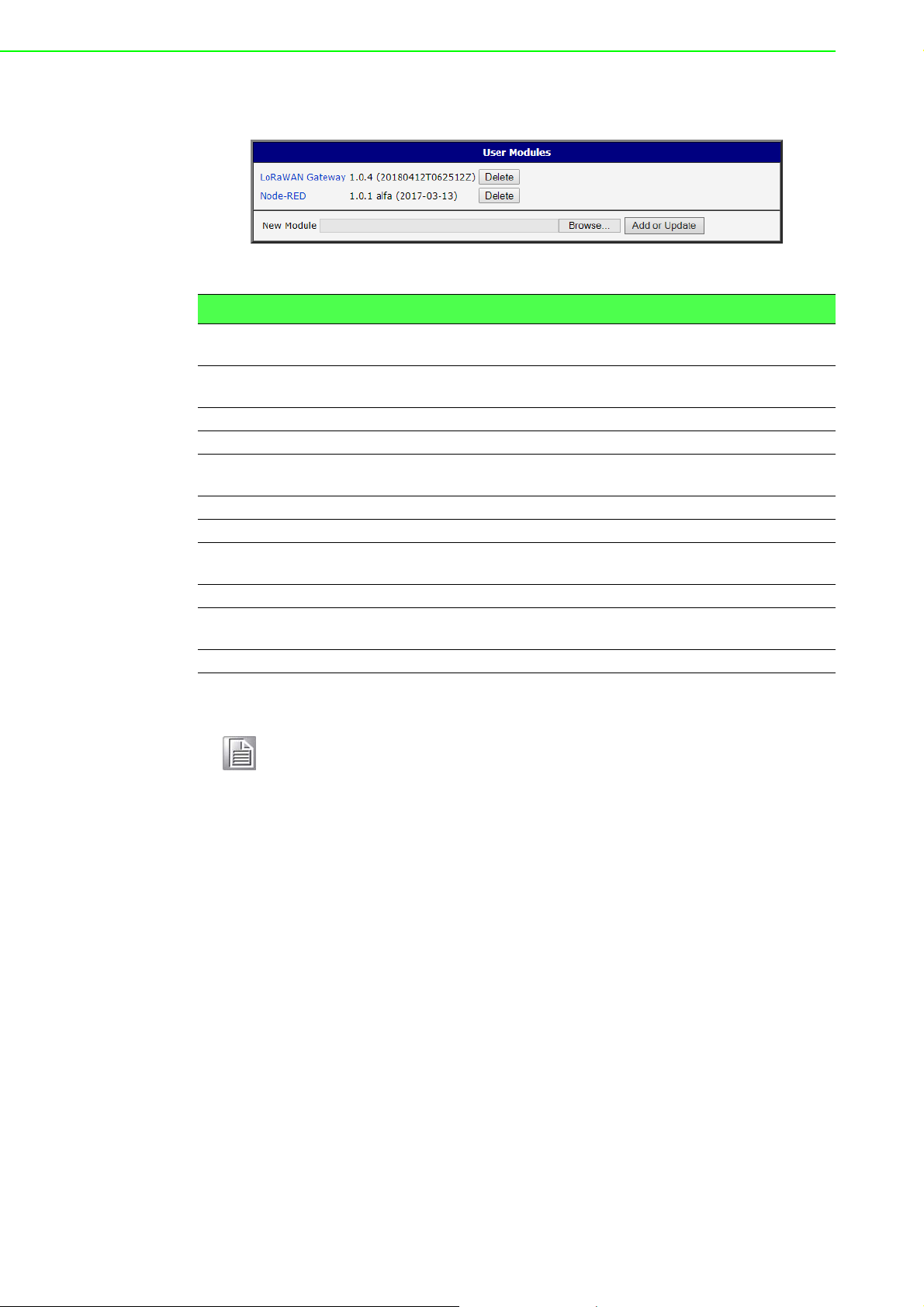
1. Login WISE-6610 Series. See “Access Interface” on page 14.
2. Go to Customization > User Modules.
3. A list of available devices display. Click on the target LoRaWAN Gateway.
Figure 4.1 Customization > User Modules
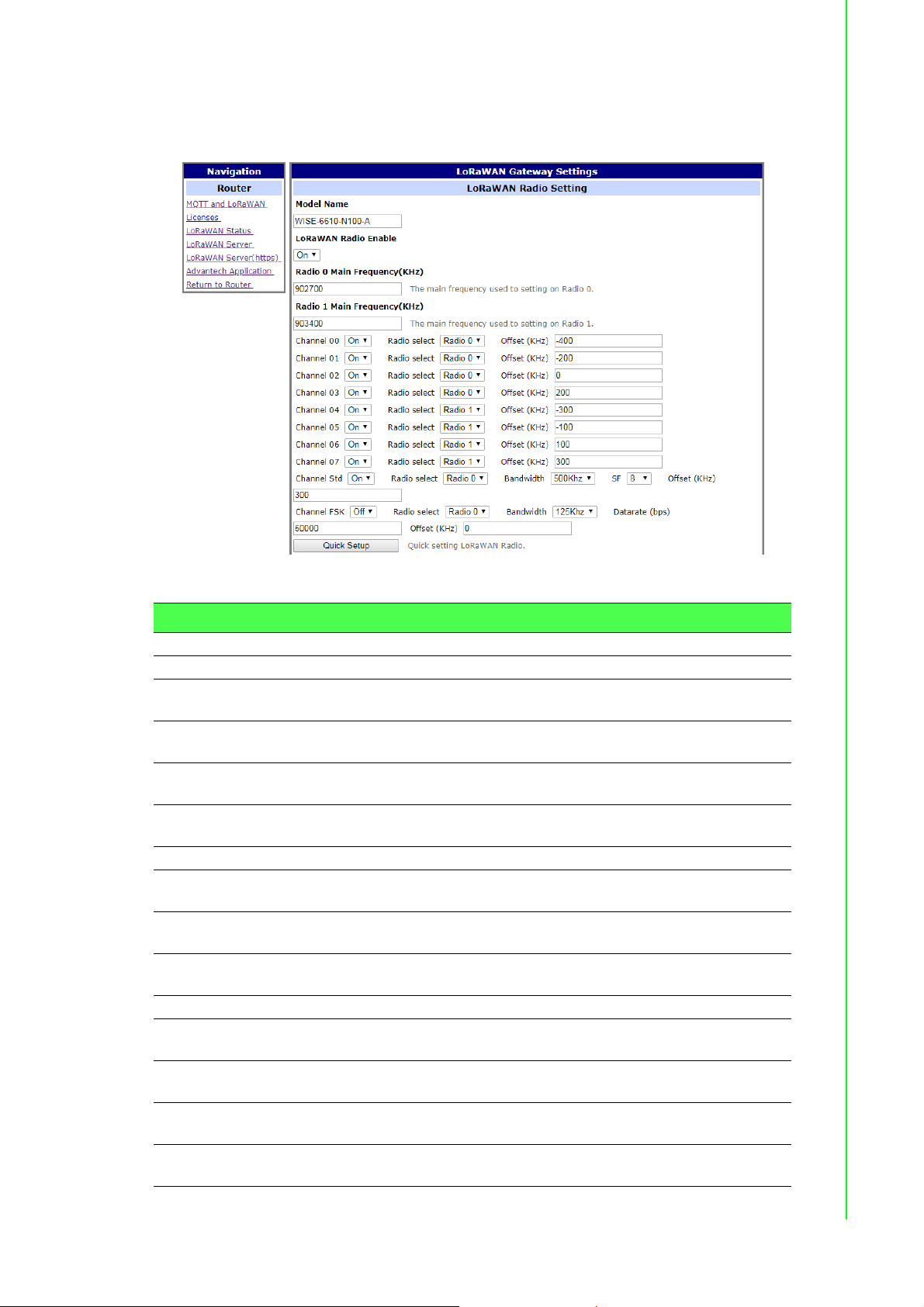
4. The Settings menu displays. In LoRaWAN Radio Enable, click the drop-down
menu to enable LoRaWAN function.
5. Configure the main frequency for radio 0 and radio 1. For radio 1, there are eight
channels and one standard channel.
Note! 1. The offset setting for the eight channels must be +/-500KHz.
2. Use Quick Setup to define the main frequency for receiving the
data from the LoRaWAN node.
3. In LoRaWAN Gateway Identifier, copy the gateway ID and set on LoRaWAN
network server.
Figure 4.2 LoRaWAN Gateway > MQTT and LoRaWAN
WISE-6610 Series User Manual 69
Page 26

4. In LoRaWAN Network Server Setting, click the drop-down menu to enable
LoRaWAN network server.
5. In MQTT Broker Enable, click the drop-down menu to enable MQTT broker.
Figure 4.3 LoRaWAN Gateway > MQTT and LoRaWAN
6. Click Save to save the configuration.
70 WISE-6610 Series User Manual
Page 27

7. Click LoRaWAN Server and enter the default user name and password (root/
root) to log into the LoRaWAN Network Server page.
Note! The LoRaWAN Network Server does not support IE or EDGE browser.
Figure 4.4 LoRaWAN Gateway > LoRaWAN Server
8. Click Infrastructure > Gateways to enter the Gateways List page.
9. Click Create to add a new gateway.
Figure 4.5 LoRaWAN Server > Infrastructure > Gateways
WISE-6610 Series User Manual 71
Page 28

10. In the Create new gateway page, configure the new gateway settings. Input the
MAC which is the LoRaW AN gateway ID shows on the LoRaW AN setting Page.
Figure 4.6 LoRaWAN Server > Infrastructure > Gateways > Create
Item Description
MAC Enter the LoRaWAN gateway ID shown on MQTT and LoRaWAN
menu.
Group Enter the opaque string with application-specific settings.
TX Chain Enter a value to identify the radio chain used for downlinks (default:
0). It shall correspond to a radio_x (e.g. radio_0) with
tx_enable: true in gateway's global_conf.json.
Antenna Gain (dBi) Enter a value to ensure the TX Power + Antenna Gain is below the
maximal allowed Equivalent Isotropic Radiated Power (EIRP) for the
given Network.
Description Enter the description for the gateway.
Submit Click Submit to save the values and update the screen.
11. Click Infrastructure > Networks to enter the Networks List page.
By default, the WISE-6610 Series pre-configures the network to support EU868,
AU915, AS923 and US902.
Figure 4.7 LoRaWAN Server > Infrastructure > Networks
72 WISE-6610 Series User Manual
Page 29

12. Click Create to create your own network frequency.
Figure 4.8 LoRaWAN Server > Infrastructure > Network > Create > General
Item Description
Name Enter the name of the network.
NetID Enter the NetID of the network. Use 000000 or 000001 for private
networks.
SubID Enter the SubID of the network in the format of HexValue:Length
which specifies the fixed bits in the DevAddr of the active node.
(optional)
Region Enter a value to determine the regional characteristics of LoRaWAN.
Coding Rate Enter a value to define the coding rate. It is regularly set on 4/5.
RX1 Join Delay (s) Enter a value to define the JOIN_ACCEPT_DELAY1.
RX2 Join Delay (s) Enter a value to define the JOIN_ACCEPT_DELAY2.
RX1 Delay (s) Enter a value to define the RECEIVE_DELAY1.
RX2 Delay (s) Enter a value to define the RECEIVE_DELAY2.
Gateway Power
Enter a value to define the default transmission power for downlinks.
(dBm)
Submit Click Submit to save the values and update the screen.
In the General tab, follow the table below when configuring a new network:
Parameter EU868 US902 CN779 EU433 AU915 CN580 AS923 KR920 IN865 RU864
Coding Rate 4/5 4/5 4/5 4/5 4/5 4/5 4/5 4/5 4/5 4/5
RX1 Join
Delay(s)
5555555555
WISE-6610 Series User Manual 73
Page 30

Parameter EU868 US902 CN779 EU433 AU915 CN580 AS923 KR920 IN865 RU864
RX2 Join
Delay(s)
RX1 Delays1111111111
RX2 Delays2222222222
Gateway
Power
Max EIRP
(dBm)
Max Power Max Max Max Max Max Max Max Max Max Max
Min Power Max -
Max Data
Rate
Initial RX1
DR Offset
Initial RX2 DRSF12
Initial RX2
Freq (MHz)
Initial
Channels
6666666666
16 26 12 12 30 19 16 23 30 16
16 30 12.15 12.15 30 19.15 16 14 30 16
Max -
14 dB
SF7
125 kHz
0000000000
125 kHz
869.525 923.3 786 434.665 923.3 505.3 923.2 921.9 866.550 869.1
0-2 0-71 0-2 0-2 0-71 0-95 0-x* 0-2 0-2 0-1
20 dB
SF8
500 kHz
SF12
500 kHz
Max -
10 dB
SF7
125 kHz
SF12
125 kHz
Max 10 dB
SF7
125 kHz
SF12
125 kHz
Max 20 dB
SF8
500 kHz
SF12
500 kHz
Max 14 dB
SF7
125 kHz
SF12
125 kHz
Max 14 dB
SF7
125 kHz
SF10
125 kHz
Max 14 dB
SF7
125 kHz
SF12
125 kHz
Max 20 dB
SF7
125 kHz
SF10
125 kHz
Max 14 dB
SF7
125 kHz
SF10
125 kHz
13. Click the ADR tab to configure the ADR settings for a specified parameter.
Figure 4.9 LoRaWAN Server > Infrastructure > Network > Create > ADR
Item Description
Max EIRP (dBm) Enter a value to specify the EIRP used in your region.
Max Power Enter a value to define the first TX Power item.
Min Power Enter a value to define the last TX Power item.
74 WISE-6610 Series User Manual
Page 31

Item Description
Max Data Rate Enter a value to define the highest DR (lowest SF) supported by the
channels in this network. Additional channels may need to be given a
different value.
Note: The Max Data Rate is not always the last item (lowest SF)
in the TX data rate table. Not all channels (frequencies) are
allowed to use all data rates. For example, in EU868, the
default channels use SF12/125 to SF7/125 only. The SF7/250
is allowed for the 867.3 MHz channel only and FSK for 867.7
MHz only.
Initial RX1 DR Offset Enter a value to define the offset between the uplink and downlink
data rates used to communicate with the end-device on the first
reception slot (RX1).
Initial RX2 DR Enter a value to define the data rate for the second reception slot
(RX2).
Initial RX2 Freq
(MHz)
Submit Click Submit to save the values and update the screen.
Enter a value to define the default frequency in the RX2 receive
window.
14. Click the Channel tab to configure the channel settings following the frequency
rule.
Figure 4.10 LoRaWAN Server > Infrastructure > Network > Create > Channel
Item Description
Initial Channels Enter a range of values to define the initial channels including a
comma-separated list of intervals, e.g. 0-2 for EU and 0-71 for US.
Channels Click Add new channels to define a list of additional channels sent to
the device during Join (CFList).
Frequency (MHz): Enter a value to define the channel fre-
quency.
Min Data Rate: Enter a value to define the lowest data rate
allowed in this channel. Enter 0 if it's not specified.
Max Data Rate: Enter a value to define the highest data ra te
allowed in this channel. Enter the global value of the ADR tab if
it's not specified.
Submit Click Submit to save the values and update the screen.
WISE-6610 Series User Manual 75
Page 32

15. Click Backends > Handlers to enter the Handlers List page.
The WISE-6610 Series handler is created by default. The LoRaWAN data
comes with the item with the Field in the handler settings.
Figure 4.11 LoRaWAN Server > Backends > Handlers
Field Type Definition
app String Application (Handler) name
devaddr Hex String DevAddr of the active node
deveui Hex String DevEUI of the device
appargs Any Application arguments for the node
battery Integer Most recent battery level reported by the device
fcnt Integer Received frame sequence number
port Integer LoRaWAN port number
data Hex String Raw application payload encoded as a hexadecimal string
datetime ISO 8601 Timestamp using the server clock
freq Number RX central frequency in MHz (unsigned float/ Hz precision)
datr String LoRa data rate identifier (e.g. SF12BW500)
codr String LoRa ECC coding rate identifier (default: 4/5)
best_gw Object Gateway with the strongest reception
mac Hex String MAC address of the gateway with the strongest reception
lsnr Number LoRa uplink SNR ratio in dB (signed float/ 0.1 dB precision)
(same as rxq.lsnr for best_gw)
rssi Number RSSI in dBm (signed integer/ 1 dB precision) (same as
rxq.rssi for best_gw)
all_gw Object List of all gateways that received the frame
76 WISE-6610 Series User Manual
Page 33

16. Click Create to add a new handler rule. This function allows you to choose the
desired uplink fields and supports the parse script option that helps you parse
the raw data received from the sensor node as shown in Figure 4.13.
Figure 4.12 LoRaWAN Server > Backends > Handlers > Create
Item Description
Application Enter the name of the handler.
Uplink Fields Enter the filter values to be forwarded to the backend connector.
Payload Enter the filter values as the format for automatic decoding.
Parse Uplink Enter the string to extract additional data fields from the uplink frame.
See Figure 4.13 for references.
Parse Event Enter the string to be forwarded to the backend connector.
Build Downlink Enter the string to create a downlink frame based on backend data
fields.
WISE-6610 Series User Manual 77
Page 34

Item Description
fun(Fields,Port, <<DEV, Temp:16, Hum:16, Sensor:16>>) ->
if
DEV==1 ->
Fields#(device => co2, temp => Temp/100, hum => Hum/100, sensor => Sensor);
DEV==2 ->
Fields#(device => co, temp => Temp/100, hum => Hum/100, sensor => Sensor);
DEV==3 ->
Fields#(device => pm25, temp => Temp/100, hum => Hum/100, sensor => Sensor);
true ->
false
end
end.
D/L Expires Click the drop-down menu to define when the downlinks may be
dropped.
Never:
– All class A downlinks for a device will be queued and eventu-
ally delivered.
– All confirmed downlinks will be retransmitted until acknowl-
edged even when a new downlink is sent.
When Superseded:
– Only the most recent class A downlinks will be scheduled for
delivery. Superseded downlinks will be dropped.
– Unacknowledged downlinks will be dropped when a
new downlink (either class A or C) is sent.
Submit Click Submit to save the values and update the screen.
Figure 4.13 Parse Uplink Sample
17. Click Backends > Connectors to enter the Connectors List page.
The connector settings define the data flow which is the rule for processing the
LoRaWAN data. For example, data comes with the handler rule should be
saved to the MQTT broker or websocket.
The broker and websocket on the WISE-6610 Series is enabled by default. The
uplink from the sensor node comes with the MQTT topic is
uplink/{devaddr} and the downlink topic is out/{devaddr}.
Figure 4.14 LoRaWAN Server > Backends > Connectors
78 WISE-6610 Series User Manual
Page 35

18. Click Create to create your own connector rule.
Figure 4.15 LoRaWAN Server > Backends > Connectors > Create
Item Description
Connector Name Enter the name of the connector.
Application Click the drop-down menu to select the application to reference a
specific backend handler.
Format Click the drop-down menu to select the format.
JSON: Encode data fields as Json structures such as {"Name-
One":ValueOne, "NameTwo":ValueTwo}.
Raw Data: Send only the binary content of the data field with out
ant port numbers nor flags.
Web Form: Encode fields in query strings such as Name-
One=ValueOne&NameTwo=ValueTwo.
URI Enter a string to define the target host which can be mqtt:// for
MQTT or mqtts:// for MQTT/SSL.
Publish Uplinks Enter a string to define a server pattern for constructing the
publication topic for uplink messages, including the actual DevEUI,
DevAddr or other data fields in the message topic. e.g. out/
{devaddr}.
Publish Events Enter a string to define a server pattern for constructing the
publication topic for event messages.
Subscribe Enter a string to define a topic for subscription. It may include broker
specific wilcards, e.g. in/#. The MQTT broker will then send
messages with a matching topic to this connecto r.
Received Topic Enter a string to define the template for parsing the topic of received
messages, e.g. in/{devaddr}. This can be used to obtain a
DevEUI, DevAddr or a device group that receives a given downlink.
Enabled Check to allow a temporarily disable on an existing connector.
WISE-6610 Series User Manual 79
Page 36

Item Description
Failed Click the drop-down menu to select the flag indicates the failure items.
badarg: Some connector parameters are bad.
network: The destination server cannot be reached.
topic: The target broker configuration is wrong.
Submit Click Submit to save the values and update the screen.
19. Click Devices > Profiles to enter the Profiles List page.
Define the profile rule for the LoRa node and assign the handler rule to each
profile. The default profiles are listed in the figure below:
Figure 4.16 LoRaWAN Server > Devices > Profiles
20. Click Create to add a new profile.
Figure 4.17 LoRaWAN Server > Devices > Profiles > Create > General
Item Description
Name Enter the name of the profile.
Network Click the drop-down menu to select the network.
Application Click the drop-down menu to select the application in use.
App Identifier Enter the name of the ap plic at ion ID .
80 WISE-6610 Series User Manual
Page 37

Item Description
Can Join? Click the drop-down menu to select a flag to prevent the device from
joining.
FCnt Check Click the drop-down menu to select the FCnt check for the device.
Strict 16-bit (defau lt) or Strict 32-bit: Indicates a standard compli-
ant counter.
Reset on zero: Behaves as a "less strict 16-bit" which allows
personalised (ABP) devices to reset the counter. This weakens
the device security a bit as more reply attacks are possible.
Disabled: Disables the check for faulty devices and destroys the
device security.
TX Window Click the drop-down menu to select the TX window for downlinks to
the device.
Auto: Choose the earliest feasible option: RX1 or RX2.
RX1: Always use the first RX window.
RX2: Always use the second RX window.
Submit Click Submit to save the values and update the screen.
21. Click the ADR tab to configure further settings for the node.
Figure 4.18 LoRaWAN Server > Devices > Profiles > Create > ADR
Item Description
ADR Mode Click the drop-down menu to determine the adaptive data rate (ADR)
mechanism for the device: Disabled, Auto-Adjust or Maintain.
Set Power Enter a value to define the power (in dBm).
Set Data Rate Enter a value to define the data rate.
Max Data Rate Enter a value to define the maximal data rate supported by the
devices.
Set Channels Enter a value to define the set of channels. The channels are given as
a comma-separated list of interfaces, e.g. 0-2 for EU, 0-71 for the
whole US band, or 0-7,64 for the first US sub-band.
WISE-6610 Series User Manual 81
Page 38

Item Description
Set RX1 DR Offset Enter a value to define the offset between the uplink and the RX1 slot
downlink data rates.
Set RX2 DR Enter a value to define the data rate for the second reception slot
(RX2).
Set RX2 Freq (MHz) Enter a value to define the default frequency in the RX2 receive
window.
Request Status? Click the drop-down menu to select the flag used to disable the st atus
requests for simple devices that do not support the function (default:
true).
Submit Click Submit to save the values and update the screen.
22. Click Devices > Activated (Nodes) to enter the Nodes List page.
Activated (Nodes) is the setting for ABP type nodes and Commissioned is for
OTAA type nodes. The LRPv2 nodes only supports ABP so the info can only be
created in the ABP options.
Figure 4.19 LoRaWAN Server > Devices > Activated (Nodes)
23. Click Create to add a new LoRaWAN node (ABP) along with its Devaddr,
APPkey and NwkKey.
Figure 4.20 LoRaWAN Server > Devices > Activated (Nodes) > Create
Item Description
DevAddr Enter the name of the node.
Profile Click the drop-down menu to select the profile for the node.
82 WISE-6610 Series User Manual
Page 39

Item Description
App Arguments Enter the opaque string with application-specific settings.
NwkSKey Enter the NwkSKey for the node.
AppSKey Enter the AppSKey for the node.
FCnt Up Enter a value to define the frame counter.
FCnt Down Enter a v a lue to define the fram e coun te r.
Submit Click Submit to save the values and update the screen.
24. Click Devices > Commissioned to enter the Devices List page.
Figure 4.21 LoRaWAN Server > Devices > Commissioned
25. Click Create to add a new LoRaWAN node (OTAA).
Figure 4.22 LoRaWAN Server > Devices > Commissioned > Create
Item Description
DevEUI Enter the DevEUI for the device.
Profile Click the drop-down menu to select the profile for the device.
App Arguments Enter the opaque string with application-specific settings.
AppEUI Enter the AppEUI for the device.
AppKey Enter the AppKey for the device.
Last Join Enter a value to define the timestamp of the last successful Join
request.
Node Enter the corresponding node.
Submit Click Submit to save the values and update the screen.
WISE-6610 Series User Manual 83
Page 40

26. After the LoRaWAN network, gateway, node, handler and connector funcitons
are enabled. Click Received Frames to enter the Received Frames page and
check the received messages.
Figure 4.23 LoRaWAN Server > Received Frames
27. Since the MQTT broker on the WISE-6610 series is enabled by default, you can
subscribe the MQTT "#" on 192.168.1.1 to receive the LoRaWAN node messages.
Figure 4.24 MQTT Subscription
84 WISE-6610 Series User Manual
Page 41

Figure 4.25 MQTT Subscription
28. Click Infrastructure > Events to enter the Events List page to view the events.
Figure 4.26 LoRaWAN Server > Infrastructure > Events
WISE-6610 Series User Manual 85
Page 42

4.2 Changing the Raw LoRa Data Format
This function parses and shows the raw data from an Advantech LRPv2 LoRa node.
Note! WISE-6610 series models does not parse data from a non-Advantech
LoRa node through the Advantech Application function.
Note! All the foregoing settings must be configured before using this function.
1. To access this page, click User Modules > LoRaWAN Gateway > Advantech
Application.
Figure 4.27 User Modules > LoRaWAN Gateway > Advantech Application
2. Click Detail to list the real data and status detail of the node.
Figure 4.28 Data and Status
86 WISE-6610 Series User Manual
Page 43

3. To get the sensor node data, the application server needs to be enabled first.
After the application server is enabled, the Advantech application server will
parse the data subscribed from the MQTT broker (WISE-6610 with topic uplink/
#) as shown in the figure below.
Figure 4.29 User Modules > LoRaWAN Gateway > MQTT and LoRaWAN
4. Click LoRaWAN Server > Devices > Activated (Nodes) to enter the Nodes
List page.
Figure 4.30 LoRaWAN Server > Activated (Nodes)
5. Edit the LoRa Node and enter Advantech in the App Arguments field. The
Advantech application server will deal with the raw data based on the info and
list the real data on the Advantech Application page.
Figure 4.31 LoRaWAN Server > Activated (Nodes) > Edit > General
WISE-6610 Series User Manual 87
Page 44

6. Not only the data will be shown on the Advantech Application pa ge, if you would
like to apply the data to other software applications, you can also subscribe
Topic “#” or direct Topic “Advantech/+/data” from the WISE-6610 MQTT server.
Figure 4.32 Applying Data to Other Software Applications
4.3 Node-RED Setup
1. Go to Customization > User Modules.
2. A list of available devices display. Click on the target Node-RED.
Figure 4.33 Customization > User Modules
3. The Settings menu displays. Click Node-RED and check the box to enable the
Node-RED and enter the port number (default: 1880).
Figure 4.34 Node-RED
4. Go to Node-RED page (http://192.168.1.1:1880/) and log in using the default
user name and password (root/root) for further configuration.
Figure 4.35 Node-RED
88 WISE-6610 Series User Manual
Page 45

www.advantech.com
Please verify specifications before quoting. This guide is intended for reference
purposes only.
All product specifications are subject to change without notice.
No part of this publication may be reproduced in any form or by any means,
electronic, photocopying, recording or otherwise, without prior written permission of the publisher.
All brand and product names are trademarks or registered trademarks of their
respective companies.
© Advantech Co., Ltd. 2018
 Loading...