

Page 1
ZenoCCU User manual | Version 0.2 1 | 25
ZenoCCU
User manual
Version: 0.2
[email protected] | zenoway.com
Page 2

User manual | Version 0.2 2 | 25
Contents
1 Introduction 4
1.1 Design elements in this manual 4
1.2 Additional documents 4
2 Product description / functional description 5
2.1 Intended use 5
2.2 Mount, operate and service the device correctly 6
2.3 Required qualification 6
2.4 Scope of delivery 6
2.5 Construction 7
2.6 Status of LEDs 7
2.7 Designation and labeling 8
3 Preparing the product 10
3.1 Unpacking the device 10
3.2 Transport 10
3.3 Storage 10
4 Technical data 10
4.1 General 10
4.2 Device dimensions 12
4.3 Interfaces 12
4.4 Antennae 14
5 Mechanical mounting 14
5.1 Safety notice 15
6 Connecting the cables and cable cover 17
6.1 Preparing the cables, cable grommets and dummy grommets 17
6.2 Plugging in the power supply cable 17
6.3 Securing the ground using ring tongue to the ground bolt 17
6.4 Securing the power supply cable to the strain relief rail 17
6.5 Connecting further cables 18
6.6 Closing off unused cable openings 18
6.7 Fitting the cable cover 18
7 Electrical installation 18
7.1 Safety notice 18
7.2 Connection to the power supply 19
7.2.1 Electrical connection to vehicles 19
7.2.2 Observe the potential ratios 20
7.2.3 Electrically isolated installation 20
7.3 Securing the ground using ring tongue to the ground bolt 20
[email protected] | zenoway.com
Page 3

User manual | Version 0.2 3 | 25
8 Operation / usage 20
8.1 Starting and shutting down 21
8.2 Status display 21
8.3 Access 21
8.4 Settings 21
8.5 Accessories 22
8.6 Antennae 22
9 Servicing and maintenance 22
9.1 Cleaning 22
9.2 Inspection and repair 23
10 End-of-life device disposal 23
11 Technical customer support 23
12 ??Form for device returns?? 24
[email protected] | zenoway.com
Page 4
User manual | Version 0.2 4 | 25
DANGER / WARNING / CAUTION
Personal injury
DANGER
a danger that will lead to immediate death or severe injury.
WARNING
a danger that can lead to death or severe injury.
CAUTION
a hazard that can lead to slight injuries.
NOTICE: Physical damage
Note on potential physical damage
"ICON" TIP
Tips for using the product
Description
Purpose
Target group
Availability
Data sheet
ZW_Datenblatt_Zeno
CAM_V1.4.pdf
Skilled personnel
Safety notice
Protection of
personnel and
physical damage
Skilled personnel
Quick start
manual
Commissioning
Skilled personnel
Manual
Complete operating
instructions
Skilled personnel and trained
users
Maintenance
manual
Maintenance
instructions
Skilled personnel
Pilot Pro
application
operating
Application reference
Skilled personnel
1 Introduction
1.1 Design elements in this manual
Notes on hazards to persons are shown as follows.
Notes on physical damage are shown as follows.
Notes using the product and further information are shown as follows.
1.2 Additional documents
[email protected] | zenoway.com
Page 5
User manual | Version 0.2 5 | 25
instructions
Pilot Pro Web UI
operating
instructions
Configuration
interface
Skilled personnel
Retain all enclosed manuals and instructions for subsequent use.
Latest manual version on the internet
The latest versions of the manuals can be found at
www.abc.xy
Observe safety notices
Observe the safety notices included with the device.
2 Product description / functional description
2.1 Intended use
The ZenoCCU is a computing unit and is designed for use in the industrial environment. Any other or
additional use beyond this is deemed improper. The operating company of the ZenoCCU shall be
responsible for any resulting damage.
This also applies to unauthorized modifications made to the device.
The ZenoCCU can be operated with the original power supply cable or a DC voltage source with 9 to 60
VDC and 70W approved by Zeno Track. The maximum operating temperature of the device is +45 °C.
Contact Zeno Track for further information and support. Intended use includes compliance with all safety
information, the permitted environmental conditions and any specifications for the device.
The ZenoCCU:
is not approved for use in the EX zone (risk of explosion), on ships and on rail vehicles.
is not approved for use in life-support systems or safety-critical systems or applications where a system
malfunction can lead to the direct or indirect endangerment of human life.
This equipment is not suitable for use in locations where children are likely to be present.
It is only permitted to use accessories that are listed in the operating manual or approved by Zeno Track for
operation with the ZenoCCU. Otherwise, any Zeno Track GmbH warranty for this device will be void.
Requirements for safe operation
The requirements are:
Proper transport and storage
Proper mounting and application
Proper maintenance and servicing
Operation by trained personnel
Observe the permitted environmental conditions
[email protected] | zenoway.com
Page 6
User manual | Version 0.2 6 | 25
The ZenoCCU is only permitted to be used under the specified environmental conditions (see chapter XXX).
2.2 Mount, operate and service the device correctly
The ZenoCCU has been designed and built according to the latest technical safety regulations. However, the
operation of the device can endanger personnel or third parties and cause damage to the device and other
material assets when, for example, the device is
installed incorrectly or configured improperly.
operated by untrained or uninstructed personnel
improperly operated and maintained.
not used as intended.
The owner/operator commitments with regards to safety (accident prevention regulations, occupational
safety)
must be observed
2.3 Required qualification
Only skilled personnel are permitted to put into operation (electrical connection and mechanical mounting)
and maintain the ZenoCCU.
Skilled personnel for the purpose of these safety notices are persons who are familiar with these procedures
and have the corresponding qualifications for their activities, such as:
Training or instruction in how to switch on and off, ground, and label power circuits and devices or
systems in accordance with the current standards for safety equipment, as well as the required
authorization.
Training or instruction in how to maintain and use appropriate safety equipment in accordance with the
current standards for safety equipment.
Training in first aid.
Users of the ZenoCCU must be trained by skilled personnel and instructed about the operation of the device
2.4 Scope of delivery
Scope of delivery
ZenoCCU
Cable duct cover
Strain relief
Cable bushings and dummy plugs
Optional additional parts
2 x Wi-Fi / Bluetooth antenna
Antenna cap
Connection cable for power supply
[email protected] | zenoway.com
Page 7
User manual | Version 0.2 7 | 25
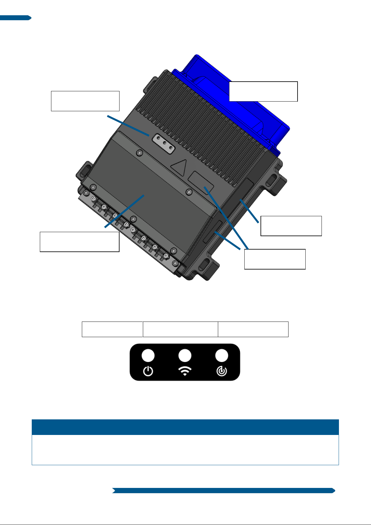
Power LED
Connection LED
Tracking LED
LED
Color
Flashing pattern
Meaning
Power
Green
ON
Supply voltage is
available and ignition
signal is present
Antenna cap
Cable duct cover
Serial numbers
Status of LEDs
Product label
2.5 Construction
2.6 Status of LEDs
The following table gives the standard configuration of the status LEDs. The specific response can be
modified via the application software.
[email protected] | zenoway.com
Page 8

User manual | Version 0.2 8 | 25
Connection
Yellow
ON
Network connection
established
Tracking
Blue
Regular flashing
Tracking running
2.7 Designation and labeling
Name plate
The nameplate is situated in a protected position on the side of the ZenoCCU. For the purposes of device
identification, it must remain legible and it not permitted to have anything affixed over it.
Serial number
The serial number is affixed to the housing in two places. One is located in a protected position on the side
of the housing. The other is in an easily visible location on the top.
[email protected] | zenoway.com
Page 9

Page 10
User manual | Version 0.2 10 | 25
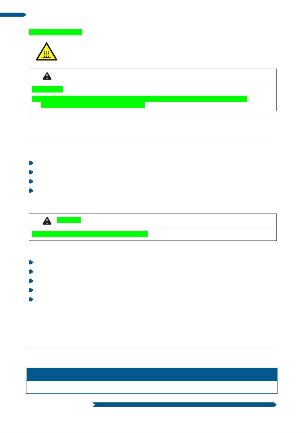
WARNING
Hot surfaces
The surfaces of the ZenoCCU can reach a surface temperature of over 70°C depending on the
environmental conditions and operating point.
CAUTION
Risk of injury due to weight and sharp-edged parts.
Article number
XXXXXXX
Housing
Aluminum pressure casting
"Caution: hot" sticker
3 Preparing the product
3.1 Unpacking the device
Open the packaging carefully to prevent damaging the device
Retain the packaging material (for any onward transport or returns)
Check the shipment for completeness and any possible damage
Always keep the supplied manuals and documents
3.2 Transport
The ZenoCCU may fall down and cause injuries due to its weight. The strain relief rail can have sharp edges
and cause cutting injuries.
Always hold the ZenoCCU by the housing with both hands.
Never use the antenna cap as a handle. It can break due to the weight involved.
Do not grip the ZenoCCU on the strain relief plate.
Use the assistance of a second person for installation work
For onward transport or return, use suitable packaging material to ensure that the device is not damaged
3.3 Storage
The ZenoCCU can also be stored in the transport packaging within the specified storage temperature range.
4 Technical data
4.1 General
[email protected] | zenoway.com
Page 11

User manual | Version 0.2 11 | 25
L x W x H (mm): 200 x 210 x 70 without antenna cap
L x W x H (mm): 225 x 210 x 70 with antenna cap
Weight
XXX g
Operating
temperature
-20 °C to +45 °C
Storage temperature
XXX to XXX
Humidity
XXXXXX
Power supply
9 - 60V DC
System performance
60 W
Protection class
IP65
Mechanical stability
EN 60721-3-5 class 5M3
CPU
INTEL Atom E3845 Quadcore 1.9GHz
RAM
4GB
Mass storage
32GB EMMC (pSLC)
Interfaces
3x 10 / 100 / 1000Mbit Ethernet
2x Power over Ethernet Class 2
1x USB 3.0
1x USB2.0 with high retention connection
2x RS232
1x CAN (isolated)
4x digital IO
4x analog input (0-10V, 0-20mA)
Digital input
Max. input voltage: 30V
Minimum high level voltage: 11V
Digital output
High level output voltage: 12V, 24V (depending on the sensor supply voltage)
Maximum output current per pin: 150mA
Analog input
Max input voltage: 13V
Voltage input measuring range: 0..10V DC
Current input measuring range: 0..20mA
Power supply for
sensors
Max. 24W
[email protected] | zenoway.com
Page 12
User manual | Version 0.2 12 | 25
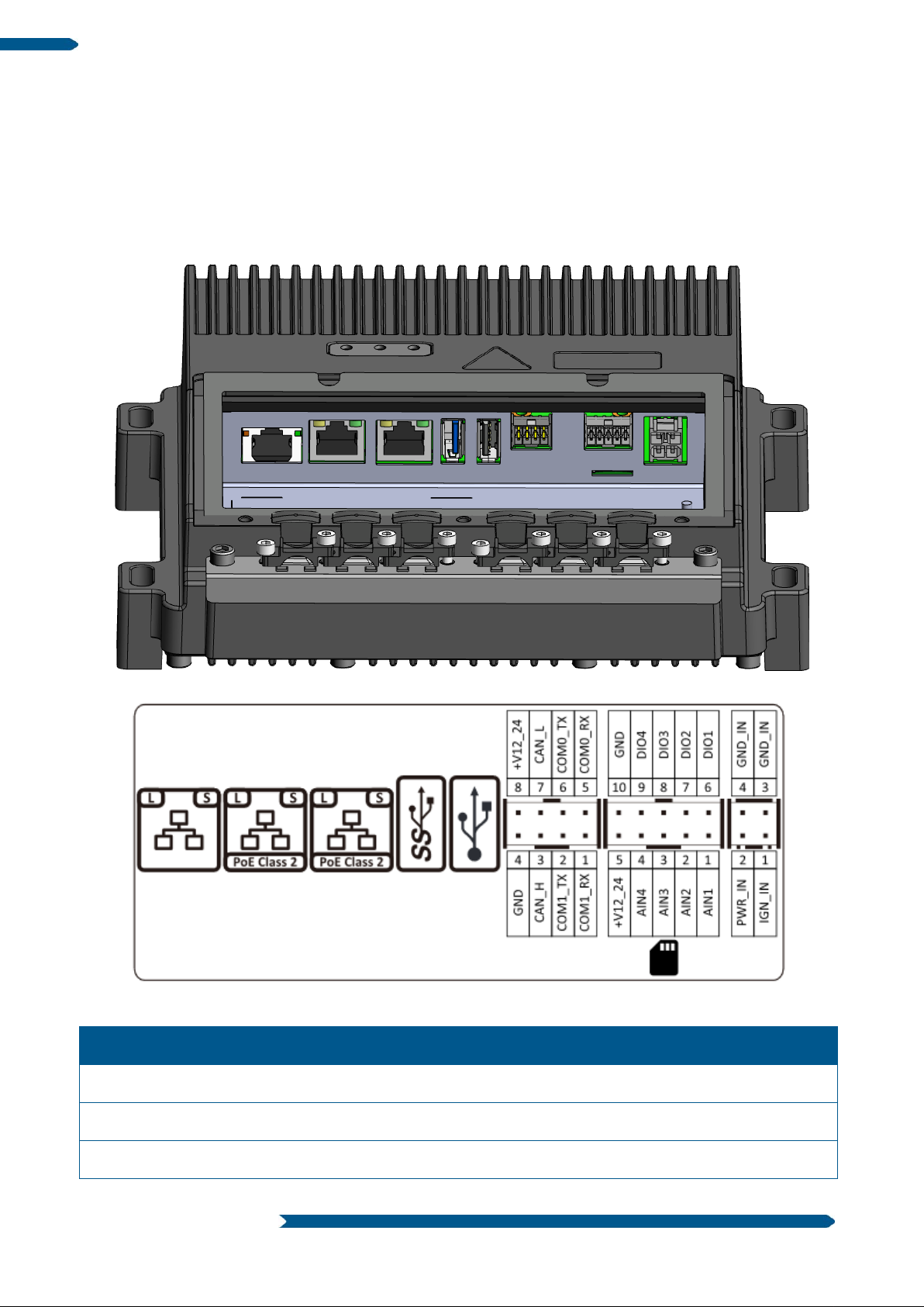
Designation
Description
LAN Port 1
10 / 100 / 1000 Mbit
LAN Port 2
10 / 100 / 1000 Mbit with Power over Ethernet Class 2
LAN Port 3
10 / 100 / 1000 Mbit with Power over Ethernet Class 2
4.2 Device dimensions
Placeholder
4.3 Interfaces
The following figure shows the interior of the cable duct as well as the sticker within the cable duct.
Interface description from left to right:
[email protected] | zenoway.com
Page 13

User manual | Version 0.2 13 | 25
USB 3.0
USB 3.0 Super Speed
Maximum current 900mA
USB 2.0
USB 2.0 high retention connection
Maximum current 400mA
Min. pull-off force 15N
Communication port
2x EIA 232
1x CAN galvanically separated
Sensor interface
4x analog input (current or voltage input)
o Max input voltage: 13V
o Voltage input measuring range: 0..10V DC
o Current input measuring range: 0..20mA
4x digital IO (configurable)
o Digital In
o Max. input voltage: 30V
o Minimum high level voltage: 11V
o Digital Out
o High level output voltage: 12V, 24V (depending on the sensor
supply voltage)
o Maximum output voltage per pin: min. 150mA
Plug-in unit for SD card
Plug-in unit direction with contact surfaces upward
Card format microSD
Max. memory size 64 GB
Plug for power supply
Input voltage 9-60V DC
Max. system performance 60W
[email protected] | zenoway.com
Page 14

User manual | Version 0.2 14 | 25
Main antenna
AUX antenna
4.4 Antennae
5 Mechanical mounting
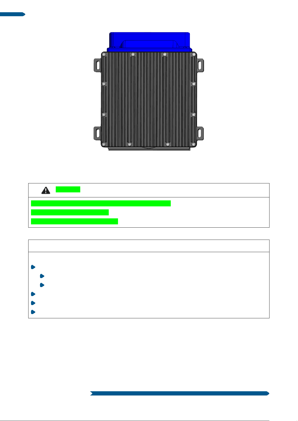
The ZenoCCU can be fastened using 4 x M6 screws with a minimal length of 35 mm. In uneven locations,
the mounting can be carried out with 3 screws.
[email protected] | zenoway.com
Page 15
User manual | Version 0.2 15 | 25
WARNING
Risk of injury and damage due to improper commissioning
Observe the safety instructions
Observe the notes on intended use
NOTICE: Physical damage
Specialist mechanical knowledge is required for correct mounting of the device.
Use suitable mounting material (screws and washers).
There are no fixing screws included in the scope of delivery.
The fixing screws must be selected according to the mounting location
Use a suitable tool
There must be a distance of XXmm between the cooling fins on the underside and the fixture
Mounting location and installation direction
5.1 Safety notice
Recommended sequence of installation steps
Requirement: The deployed system must be correctly prepared.
1. Find a suitable mounting position for the ZenoCCU.
2. Secure the ZenoCCU at the installation site.
3. Connect the external accessories to the ZenoCCU.
4. Install an easily accessible disconnecting device such as a switch close to the device.
5. Connect the power supply
6. Seal the cable passages with sealing grommets and dummy grommets.
[email protected] | zenoway.com
Page 16
User manual | Version 0.2 16 | 25
WARNING
Hazardous voltage, electric shock from contact with live parts.
Do not put the ZenoCCU into operation if it has signs of damage.
Do not open or modify the ZenoCCU.
Only connect or disconnect electrical connections when the device is in a de-energized state.
Observe the manufacturer specifications for the usage object on which the ZenoCCU is installed.
Observe the requirements of the manufacturer for the attachment of auxiliary devices and the
connection of auxiliary consumers.
This is particularly important when welding or drilling supporting parts.
Observe the manufacturer’s instructions for connecting additional loads, for example, in conjunction
with an emergency shut-off switch.
Risk of accident due to unstable attachment of the ZenoCCU
When installing the ZenoCCU, ensure that if the bracket breaks (e.g. because of a stress fracture) no-
one will be injured.
Alternatively, please put appropriate safety measures in place (e.g. attach an additional security cable)
Risk of accident due to limited field of view of the driver
Never mount the ZenoCCU such that the driver is restricted in terms of viewing range and freedom of
movement.
This also applies to additional devices and cables
Caution
Sharp-edged parts
The strain relief rail of the ZenoCCU can have sharp edges and cause cutting injuries.
Do not hold by the strain relief plate.
WARNING
Radio wave emission in the vicinity of persons
Install the ZenoCCU so that persons maintain a minimum distance of 20 cm to the antenna.
Observe the applicable regulations for your deployment location/country with regard to frequencies
and the maximum permissible transmitting power. Responsibility for this lies with the company
operating the ZenoCCU. The regulatory authorities in the relevant country can provide information on
this.
WARNING
7. Fasten the strain relief devices
8. Seal the cable cover
[email protected] | zenoway.com
Page 17

User manual | Version 0.2 17 | 25
Radio wave emission in the vicinity of persons
Install the ZenoCCU so that persons maintain a minimum distance of 20 cm to the antenna.
Observe the applicable regulations for your deployment location/country with regard to frequencies
and the maximum permissible transmitting power. Responsibility for this lies with the company
operating the ZenoCCU. The regulatory authorities in the relevant country can provide information on
this.
NOTICE
The cable grommet must completely surround the cable. The opening of the cable grommet must be
slightly smaller than the cable diameter. If the opening is too large or too small, the sealing of the device
will not be ensured.
6 Connecting the cables and cable cover
6.1 Preparing the cables, cable grommets and dummy grommets
Cable sealing set and strain relief (included as standard)
Correctly lay out ready all cables that are to be connected.
Check the cable diameters. The cable grommet used depends on the cable diameter.
6.2 Plugging in the power supply cable
The power supply plug should be locked when inserted. The lock must be pointing upward when inserted.
6.3 Securing the ground using ring tongue to the ground bolt
6.4 Securing the power supply cable to the strain relief rail
Place the power supply cable, with cable grommet, in the strain relief rail cable passage
Secure the cable against slipping using a cable tie if required
Place one cable clip on the power supply cable
Secure the cable clip to the strain relief rail using 2 mounting screws (M3x10)
Tighten up the mounting screws in opposite pairs
[email protected] | zenoway.com
Page 18

User manual | Version 0.2 18 | 25
NOTICE
Tighten the mounting screws sufficiently but make sure not to pinch the cable. Otherwise, the cables may
break or the insulation may be damaged.
NOTICE: Physical damage
Only connect accessories that have been checked by Zeno Track and approved for the ZenoCCU.
WARNING
Electrical shock due to lack of disconnecting device.
The ZenoCCU is not equipped with disconnecting devices that are accessible from the outside; it does not
have switches.
…
6.5 Connecting further cables
Procedure as described for the power supply cable:
Insert cable
Fit the appropriate cable grommet
Insert into the cable passage
If necessary, secure cable using cable tie
Secure using cable clip and screws to the strain relief rail
6.6 Closing off unused cable openings
All unused cable passages must be sealed with dummy grommets so that they are air-tight.
6.7 Fitting the cable cover
Place the cable cover into the cut-out section in the housing
Loosely screw the M3x5 screws into the cable cover holes
…
7 Electrical installation
7.1 Safety notice
To enable the device to be quickly disconnected from the power supply in emergency situations:
Install an easily accessible disconnecting device close to the device.
Make sure that the disconnecting device disconnects all power supply lines.
[email protected] | zenoway.com
Page 19

User manual | Version 0.2 19 | 25
WARNING
Electrical shock due to insufficient emergency shut-off
WARNING
Electric shock, fire due to incorrect cable routing or insufficient grounding.
This product is intended to be supplied by an UL certified power supply or dc source suitable for use at
minimum Tma 45 degree C whose output meets SELV or ES1 and is rated 9-60Vdc, 7.2-1.1A min., if
you need further assistance, please contact Zeno Track for further information
Ensure to connect the power cord to a socket-outlet with earthing connection.
Use only original power supply cables from Zeno Track.
Make sure that the power supply cables are run without kinks and are mechanically protected
(securely protected against crushing and abrading).
The DC+ - connecting cable must be protected by a maximum 30 A T fuse.
The ignition connecting cable must be protected by a fuse of the following type: 5x20 mm T 125 mA L
/ 250 V, for example Wickmann195-125 mA / 250 V.
Observe correct voltage ranges.
Ensure that power supply cable is fused correctly.
Observe the labeling on the cable and connect the power supply cable with the correct polarity.
Cut the power supply cable to the minimum length. This avoids tangled cables and improves the
quality of the power supply.
Connect the power supply cable to a suitable place. Ensure that the connecting cable has an
adequate cross section and ampacity at the connection point.
If the emergency stop switch of the object being used does not switch off the ZenoCCU, there is a risk of
electric shock.
Install the ZenoCCU and the emergency stop switch so that the DLT-V4108 also switches off when the
emergency stop switch is operated.
7.2 Connection to the power supply
7.2.1 Electrical connection to vehicles
Observe the following when connecting/removing external devices:
−Only connect accessories that have been checked by Zeno Track and approved for the ZenoCCU.
−The DLT -V4108 may not be connected to the power supply if external devices are being
connected/removed (not applicable for USB devices). Otherwise considerable damage could be caused to
both the DLT -V4108 and the peripheral devices.
−Make sure that peripherals with their own power supply are either switched on at the same time as the DLT
-V4108 or after the start of the DLT -V4108.
−Otherwise, you must ensure that a backflow from the external device to the DLT -V4108 cannot take place.
−Only power up the DLT -V4108 when all devices have been connected and the DLT-V83 has been closed
correctly (remember the cable cover!).
[email protected] | zenoway.com
Page 20

User manual | Version 0.2 20 | 25
NOTICE: Physical damage
Incorrect operation can cause damage to and downtimes on the ZenoCCU and the connected overall
system. Operators of the ZenoCCU must be trained in the handling of the device.
7.2.2 Observe the potential ratios
In the ZenoCCU, the logic ground and the shield ground are firmly connected to each other. Logic ground is
the ground (GND) used to supply the internal parts and components (e.g. CPU). All cable shields and the
housing are connected to shield ground. As the power supply unit of the ZenoCCU is not galvanically
separated, all ground connections are laid on DC- of the forklift. The chassis of some forklifts is on DC+. This
may cause malfunctions or irreparable damage. In this case, the ZenoCCU must be mounted with isolation.
Always attach ring tongue of the supply cable to the provided ground bolt situated on the connector panel.
The other end of the yellow-green power supply cable must be connected to the vehicle’s chassis. Connect
the power supply cable of the ZenoCCU as directly as possible to the battery and not to power supply lines
with a great deal of interference (e.g. the engine power supply) or otherwise affected by consumers.
Connecting the ZenoCCU to large electrical loads, such as converters for the forklift motor may result in
random restarts, malfunctions and/or irreparable damage to the device.
If you want to connect devices fed by other power sources (e.g. printers), be sure to power up the peripheral
devices at the same time or after the ZenoCCU; otherwise, you may encounter start-up problems,
malfunctions or even irreparable damage to the device.
7.2.3 Electrically isolated installation
Due to a variety of technical properties of forklifts and forklift trucks, it can be necessary to electrically isolate
the ZenoCCU from the chassis of the vehicle to prevent malfunctions. The necessity of this must be studied
on a case-by-case basis, however, it is recommended for vehicles with potential-free chassis.
For example, using rubber buffers ensures that the ZenoCCU has no electrically conducting connection to
the vehicle chassis. Moreover, the peripheral equipment and its cabling must be attached electrically isolated.
If external antennas are being used, you must ensure that the antennas are isolated at the mounting point on
the vehicle chassis.
7.3 Securing the ground using ring tongue to the ground bolt
8 Operation / usage
Different temperature and air humidity.
If the ZenoCCU is alternately used between very different temperatures and air humidity conditions,
condensation can occur in the and on the device.
To prevent damage to the device, allow sufficient acclimation time before using (moisture must evaporate).
Cable
Ensure that there are no objects lying on the cable, and that no-one can step on or trip over the cables.
[email protected] | zenoway.com
Page 21

User manual | Version 0.2 21 | 25
NOTICE: Physical damage
Do not disconnect the ZenoCCU from the power supply during ongoing operation.
When disconnecting a cable, always unplug at the connection plug, not on the cable itself.
Always keep the connection plug when unplugging it to avoid damage to the pins.
When connecting a cable, align the connection plug correctly.
If strain relief devices are fitted, these must be used.
Overvoltage on the ZenoCCU when charging the battery of the connected system.
While the battery of the connected system is being charged, the ZenoCCU must be disconnected from this
battery. Or it must be ensured that the maximum permitted input voltage of the ZenoCCU is not exceeded.
8.1 Starting and shutting down
The ZenoCCU starts depending on the setting when applying the supply voltage or when switching on the
ignition signal.
After switching off the ignition, the system continues to run for an adjustable time until the system is shut
down.
8.2 Status display
The status display is carried out on the device solely via the status LEDs on the top of the housing. For
further details, see chapter 2.
8.3 Access
In the standard configuration, each ZenoCCU creates a Wi-Fi access point with the SSID
ZenoCCU-<Serial number>. e.g.: ZenoCCU-???????
<Serial number> corresponds here to the number affixed to the device.
For access it is possible to connect to the access point, where the computer is assigned an IP address by
the ZenoCCU computer.
Wi-Fi connection data
Encryption: WPA2
Default password: 1223334444
IP address of the ZenoCCU: 172.26.20.1
Ethernet connection data
DHCP pre-configured, after timeout the IP address 192.168.0.2 on the first Ethernet port
The configuration is carried out via the remote desktop (uses the VNC protocol) or the Pilot Pro Web UI.
Default password for the VNC connection: Qwert_01
8.4 Settings
Basic and advanced configurations can be found in the commissioning instructions for the controller software
().
[email protected] | zenoway.com
Page 22

User manual | Version 0.2 22 | 25
Accessories
Article number
Sensor cable (5m) (for connecting up to 4 external sensors)
10304025
Ethernet cable (5m)
90108025
Power supply / ignition cable (5m)
24V power adapter
Remove if necessary
ZenoSIB with 4 M12 connections
90208100
WARNING
Hazardous voltage, electric shock from contact with live parts when cleaning the device
NOTICE: Physical damage
Cleaning the housing
Clean the housing with a damp cloth.
Never use chemical solvents to clean the touchscreen.
Do not use acidic or alkaline solutions.
8.5 Accessories
8.6 Antennae
Integrated antennae
2 x under the antenna cap for 2.4 GHz and 5 GHz.
9 Servicing and maintenance
Only the manufacturer and its authorized service centers may perform the following measures on the
device:
Open the device
Repairs
Modifications
Replacing components
9.1 Cleaning
To prevent an electric shock:
Switch off the ZenoCCU before cleaning.
Disconnect from the power supply.
Disconnect connected accessories.
[email protected] | zenoway.com
Page 23

User manual | Version 0.2 23 | 25
WARNING
Risk of accident due to unstable attachment of the ZenoCCU to vehicles
If the attachment of the ZenoCCU becomes loose and breaks during motion, this can lead to
severe accidents.
Check at regular intervals to ensure that the mounting screws on the ZenoCCU are not loose.
Never open the equipment. For safety reasons, the equipment should be opened only by qualified
skilled person.
CAUTION
Risk of explosion if the battery is replaced by an incorrect type
9.2 Inspection and repair
10 End-of-life device disposal
xxxx
11 Technical customer support
Please contact your distributor,
sales representative or customer service for technical support.
Please have the following information available:
Product name
Serial number
Description of the connected accessory
General description of the problem
Zeno Track Service and Support
www.zenoway.com
email: [email protected]
Tel.: +43 1 797 22 - 2100
Manufacturer address
Zeno Track GmbH
Geiereckstrasse 6
A-1110 Wien | Vienna
Ö sterreich | Austria
[email protected] | zenoway.com
Page 24

User manual | Version 0.2 24 | 25
Warranty
?????
© …..!
Information in this document is subject to change – also without prior notice. Zeno Track GmbH assumes no
liability for technical inaccuracies, typographic errors or faults in this document. DLoG GmbH accepts no
liability for damage caused directly or indirectly by the delivery, performance or use of this document.
12 ??Form for device returns??
[email protected] | zenoway.com
Page 25

User manual | Version 0.2 25 | 25
Federal Communication Commission Interference
Statement
This device complies with Part 15 of the FCC Rules. Operation is subject to the following two
conditions: (1) This device may not cause harmful interference, and (2) this device must accept any
interference received, including interference that may cause undesired operation.
NOTE: This equipment has been tested and found to comply with the limits for a Class A digital device,
pursuant to part 15 of the FCC Rules. These limits are designed to pro-vide reasonable protection against
harmful interference when the equipment is operate din a commercial environment. This equipment generates,
uses, and can radiate radiofrequency energy and, if not installed and used in accordance with the instruction
manual, may cause harmful interference to radio communications. Operation of this equipment in a residential
area is likely to cause harmful interference in which case the user will be required to correct the interference at
his own expense.
FCC Caution: Any changes or modifications not expressly approved by the party responsible for compliance
could void the user's authority to operate this equipment.
This transmitter must not be c
transmitter.
This device meets all the other requirements specified in Part 15E, Section 15.407 of the FCC Rules.
Radiation Exposure Statement:
This equipment complies with FCC radiation exposure limits set forth for an uncontrolled
environment. This equipment should be installed and operated with minimum distance 20cm
between the radiator & your body.
FOR COUNTRY CODE SELECTION USAGE (WLAN DEVICES)
Note: The country code selection is for non-US model only and is not available to all US model. Per
FCC regulation, all WiFi product marketed in US must fixed to US operation channels only.
o-located or operating in conjunction with any other antenna or
[email protected] | zenoway.com
 Loading...