

Page 1

User Manual
WISE-4210 Series
Page 2

Copyright
Part No. 2003421020 Edition 1
Printed in Taiwan November 2018
The documentation and the software included with this product are copyrighted 2018
by Advantech Co., Ltd. All rights are reserved. Advantech Co., Ltd. reserves the right
to make improvements in the products described in this manual at any time without
notice. No part of this manual may be reproduced, copied, translated or transmitted
in any form or by any means without the prior written permission of Advantech Co.,
Ltd. Information provided in this manual is intended to be accurate and reliable. However, Advantech Co., Ltd. assumes no responsibility for its use, nor for any infringements of the rights of third parties, which may result from its use.
Acknowledgements
Intel and Pentium are trademarks of Intel Corporation.
Microsoft Windows and MS-DOS are registered trademarks of Microsoft Corp.
All other product names or trademarks are properties of their respective owners.
Product Warranty (2 years)
Advantech warrants to you, the original purchaser, that each of its products will be
free from defects in materials and workmanship for two years from the date of purchase.
This warranty does not apply to any products which have been repaired or altered by
persons other than repair personnel authorized by Advantech, or which have been
subject to misuse, abuse, accident or improper installation. Advantech assumes no
liability under the terms of this warranty as a consequence of such events.
Because of Advantech’s high quality-control standards and rigorous testing, most of
our customers never need to use our repair service. If an Advantech product is defective, it will be repaired or replaced at no charge during the warranty period. For outof-warranty repairs, you will be billed according to the cost of replacement materials,
service time and freight. Please consult your dealer for more details.
If you think you have a defective product, follow these steps:
1. Collect all the information about the problem encountered. (For example, CPU
speed, Advantech products used, other hardware and software used, etc.) Note
anything abnormal and list any onscreen messages you get when the problem
occurs.
2. Call your dealer and describe the problem. Please have your manual, product,
and any helpful information readily available.
3. If your product is diagnosed as defective, obtain an RMA (return merchandize
authorization) number from your dealer. This allows us to process your return
more quickly.
4. Carefully pack the defective product, a fully-completed Repair and Replacement
Order Card and a photocopy proof of purchase date (such as your sales receipt)
in a shippable container. A product returned without proof of the purchase date
is not eligible for warranty service.
5. Write the RMA number visibly on the outside of the package and ship it prepaid
to your dealer.
WISE-4210 Series User Manual ii
Page 3

Declaration of Conformity
CE
This product has passed the CE test for environmental specifications. Test conditions
for passing included the equipment being operated within an industrial enclosure. In
order to protect the product from being damaged by ESD (Electrostatic Discharge)
and EMI leakage, we strongly recommend the use of CE-compliant industrial enclosure products.
FCC Class A
Note: This equipment has been tested and found to comply with the limits for a Class
A digital device, pursuant to part 15 of the FCC Rules. These limits are designed to
provide reasonable protection against harmful interference when the equipment is
operated in a commercial environment. This equipment generates, uses, and can
radiate radio frequency energy and, if not installed and used in accordance with the
instruction manual, may cause harmful interference to radio communications. Operation of this equipment in a residential area is likely to cause harmful interference in
which case the user will be required to correct the interference at his own expense.
Technical Support and Assistance
1. Visit the Advantech web site at www.advantech.com/support where you can find
the latest information about the product.
2. Contact your distributor, sales representative, or Advantech's customer service
center for technical support if you need additional assistance. Please have the
following information ready before you call:
– Product name and serial number
– Description of your peripheral attachments
– Description of your software (operating system, version, application software,
etc.)
– A complete description of the problem
– The exact wording of any error messages
iii WISE-4210 Series User Manual
Page 4

Warnings, Cautions and Notes
Warning! Warnings indicate conditions, which if not observed, can cause personal
injury!
Caution! Cautions are included to help you avoid damaging hardware or losing
data. e.g.There is a danger of a new battery exploding if it is incorrectly
installed. Do not attempt to recharge, force open, or heat the battery.
Replace the battery only with the same or equivalent type recommended by the manufacturer. Discard used batteries according to the
manufacturer's instructions.
Note! Notes provide optional additional information.
Document Feedback
To assist us in making improvements to this manual, we would welcome comments
and constructive criticism. Please send all such - in writing to: support@advantech.com
Package List
Before setting up the system, check that the items listed below are included and in
good condition. If any item does not accord with the table, please contact your dealer
immediately.
WISE-4210-APNA/UA
1 x WISE-4210-APNA/UA module
1 x Mounting bracket
1x China RoHS (UA series only)
WISE-4210-S231NA/UA
1 x WISE-4210-S231NA/UA module
1 x Mounting bracket
1x China RoHS (UA series only)
WISE-4210-S251NA/UA
1 x WISE-4210-S251NA/UA module
1 x Mounting bracket
1x China RoHS (UA series only)
WISE-4210 Series User Manual iv
Page 5

Safety Instructions
1. Read these safety instructions carefully.
2. Keep this User Manual for later reference.
3. Disconnect this equipment from any AC outlet before cleaning. Use a damp
cloth. Do not use liquid or spray detergents for cleaning.
4. For plug-in equipment, the power outlet socket must be located near the equip-
ment and must be easily accessible.
5. Keep this equipment away from humidity.
6. Put this equipment on a reliable surface during installation. Dropping it or letting
it fall may cause damage.
7. The openings on the enclosure are for air convection. Protect the equipment
from overheating. DO NOT COVER THE OPENINGS.
8. Make sure the voltage of the power source is correct before connecting the
equipment to the power outlet.
9. Position the power cord so that people cannot step on it. Do not place anything
over the power cord.
10. All cautions and warnings on the equipment should be noted.
11. If the equipment is not used for a long time, disconnect it from the power source
to avoid damage by transient overvoltage.
12. Never pour any liquid into an opening. This may cause fire or electrical shock.
13. Never open the equipment. For safety reasons, the equipment should be
opened only by qualified service personnel.
14. If one of the following situations arises, get the equipment checked by service
personnel:
15. The power cord or plug is damaged.
16. Liquid has penetrated into the equipment.
17. The equipment has been exposed to moisture.
18. The equipment does not work well, or you cannot get it to work according to the
user's manual.
19. The equipment has been dropped and damaged.
20. The equipment has obvious signs of breakage.
21. DO NOT LEAVE THIS EQUIPMENT IN AN ENVIRONMENT WHERE THE
STORAGE TEMPERATURE MAY GO BELOW -20° C (-4° F) OR ABOVE 60° C
(140° F). THIS COULD DAMAGE THE EQUIPMENT. THE EQUIPMENT
SHOULD BE IN A CONTROLLED ENVIRONMENT.
22. CAUTION: DANGER OF EXPLOSION IF BATTERY IS INCORRECTLY
REPLACED. REPLACE ONLY WITH THE SAME OR EQUIVALENT TYPE
RECOMMENDED BY THE MANUFACTURER, DISCARD USED BATTERIES
ACCORDING TO THE MANUFACTURER'S INSTRUCTIONS.
23. The sound pressure level at the operator's position according to IEC 704-1:1982
is no more than 70 dB (A).
DISCLAIMER: This set of instructions is given according to IEC 704-1. Advantech
disclaims all responsibility for the accuracy of any statements contained herein.
v WISE-4210 Series User Manual
Page 6

Safety Precaution - Static Electricity
This transmitter must not be co-located or operating in conjunction with any other antenna or
transmitter.
FCC Caution: Any changes or modifications not expressly approved by the party
responsible for compliance could void the user's authority to operate this equipment.
Follow these simple precautions to protect yourself from harm and the products from
damage.
To avoid electrical shock, always disconnect the power from your PC chassis
before you work on it. Don't touch any components on the CPU card or other
cards while the PC is on.
Disconnect power before making any configuration changes. The sudden rush
of power as you connect a jumper or install a card may damage sensitive electronic components.
NCC 警语
第十二條 經型式認證合格之低功率射頻電機,非經許可,公司、商號或使用者均不得
擅自變更頻率、加大功率或變更原設計之特性及功能。
第十四條 低功率射頻電機之使用不得影響飛航安全及干擾合法通信;經發現有干擾
現象時,應立即停用,並改善至無干擾時方得繼續使用。前項合法通信,指依電信法
規定作業之無線電通信。低功率射頻電機須忍受合法通信或工業、科學及醫療用電波
輻射性電機設備之干擾。
FOR MOBILE DEVICE USAGE (>20cm/low power)
Radiation Exposure Statement:
This equipment complies with FCC radiation exposure limits set forth for an uncon-
trolled environment. This equipment should be installed and operated with minimum
distance 20cm between the radiator & your body.
FOR COUNTRY CODE SELECTION USAGE (WLAN DEVICES)
Note: The country code selection is for non-US model only and is not available to all
US model. Per FCC regulation, all WiFi product marketed in US must fixed to US
operation channels only.
Industry Canada statement:
This device complies with ISED’s licence-exempt RSSs. Operation is subject to the
following two conditions: (1) This device may not cause harmful interference, and (2)
this device must accept any interference received, including interference that may
cause undesired operation.
Le présent appareil est conforme aux CNR d’ ISED applicables aux appareils radio
exempts de licence. L’exploitation est autorisée aux deux conditions suivantes : (1) le
dispositif ne doit pas produire de brouillage préjudiciable, et (2) ce dispositif doit
accepter tout brouillage reçu, y compris un brouillage susceptible de provoquer un
fonctionnement indésirable.
WISE-4210 Series User Manual vi
Page 7

FOR MOBILE DEVICE USAGE (>20cm/low power)
Radiation Exposure Statement:
This equipment complies with ISED radiation exposure limits set forth for an uncon-
trolled environment. This equipment should be installed and operated with minimum
distance 20cm between the radiator & your body.
Déclaration d'exposition aux radiations:
Cet équipement est conforme aux limites d'exposition aux rayonnements ISED
établies pour un environnement non contrôlé. Cet équipement doit être installé et
utilisé avec un minimum de 20 cm de distance entre la source de rayonnement et
votre corps.
DETACHABLE ANTENNA USAGE
This radio transmitter (IC: M82-WISE4210 / Model: WISE-4210-S231, WISE-4210S251, WISE-4210-AP) has been approved by ISED to operate with the antenna type
listed below with maximum permissible gain indicated. Antenna types not included in
this list, having a gain greater than the maximum gain indicated for that type, are
strictly prohibited for use with this device.
Le présent émetteur radio (IC: M82-WISE4210 / Model: WISE-4210-S231, WISE4210-S251, WISE-4210-AP) a été approuvé par ISED pour fonctionner avec les
types d'antenne énumérés ci-dessous et ayant un gain admissible maximal. Les
types d'antenne non inclus dans cette liste, et dont le gain est supérieur au gain maximal indiqué, sont strictement interdits pour l'exploitation de l'émetteur.
Approved antenna(s) list
Type Gain Brand Manufacturer
Dipole 2dBi PSA 1750008836-01
1750008837-01
vii WISE-4210 Series User Manual
Page 8

WISE-4210 Series User Manual viii
Page 9

Contents
Chapter 1 Product Overview ................................1
1.1 Series Family and Specifications .............................................................. 2
1.2 Mechanical Design and Dimensions ......................................................... 2
Figure 1.1 WISE-4210 Dimension Front & Side .......................... 2
1.3 LED Definition ........................................................................................... 3
1.3.1 WISE-4210-AP.............................................................................. 3
Figure 1.2 WISE-4210-AP LED Indicator .................................... 3
Figure 1.3 WISE-4210-AP LAN Port LED.................................... 3
1.3.2 WISE-4210-S231 .......................................................................... 4
Figure 1.4 WISE-4210-S231 LED Indicator................................. 4
1.3.3 WISE-4210-S251 .......................................................................... 7
Figure 1.5 WISE-4210-S251 LED Indicator................................. 7
1.4 Membrane Button.................................................................................... 10
Figure 1.6 WISE-4210 Membrane Button.................................. 11
1.5 Battery Power Switch .............................................................................. 12
Figure 1.7 WISE-4210 Battery Switch ....................................... 12
1.6 Package Information ............................................................................... 12
Chapter 2 General Specification........................15
2.1 General Specification .............................................................................. 16
2.1.1 Wireless Interface ....................................................................... 16
2.1.2 General ....................................................................................... 16
2.1.3 Power.......................................................................................... 17
2.1.4 Software...................................................................................... 17
2.1.5 Configuration Interface................................................................ 18
2.2 WISE-4210-AP........................................................................................ 18
2.2.1 Uplink Communication Port ........................................................ 18
2.2.2 Pin Assignment ........................................................................... 18
Figure 2.1 WISE-4210-AP Pin Assignment ............................... 18
2.2.3 Block Diagram............................................................................. 19
Figure 2.2 WISE-4210-AP Block Diagram................................. 19
2.3 WISE-4210-S231 .................................................................................... 19
2.3.1 I/O Specifications ........................................................................ 19
2.3.2 Pin Assignment ........................................................................... 20
Figure 2.3 WISE-4210-S231 Pin Assignment............................ 20
2.3.3 Block Diagram............................................................................. 20
Figure 2.4 WISE-4210-S231 Block Diagram ............................. 20
2.4 WISE-4210-S251 .................................................................................... 20
2.4.1 I/O Specifications ........................................................................ 20
2.4.2 Pin Assignment ........................................................................... 21
Figure 2.5 WISE-4210-S251 Pin Assignment............................ 21
2.4.3 Block Diagram............................................................................. 21
Figure 2.6 WISE-4210-S251 Block Diagram ............................. 21
2.4.4 Application Wiring ....................................................................... 22
Figure 2.7 WISE-4210-S251 Digital Input Wiring Diagram........ 22
Figure 2.8 WISE-4210-S251 RS-485 Wiring Diagram............... 22
Chapter 3 Hardware Installations ......................23
3.1 Interface Introduction .............................................................................. 24
Figure 3.1 WISE-4210 Interface Introduction ............................ 24
3.2 Mounting ................................................................................................. 24
ix WISE-4210 Series User Manual
Page 10

Figure 3.2 WISE-4000 Series Mounting Kit Dimensions ........... 25
3.2.1 DIN-Rail Mounting ...................................................................... 25
Figure 3.3 DIN Mounting Install ................................................. 25
Figure 3.4 DIN Mounting Front .................................................. 26
Figure 3.5 DIN Mounting Back .................................................. 26
3.2.2 Wall Mounting............................................................................. 27
Figure 3.6 Wall Mounting Install 1 ............................................. 27
Figure 3.7 Wall Mounting Install 2 ............................................. 28
3.2.3 Pole Mounting............................................................................. 29
Figure 3.8 Pole Mounting Front ................................................. 29
Figure 3.9 Pole Mounting Back ................................................. 30
3.3 Wiring and Connections.......................................................................... 30
3.3.1 Power Supply Wiring .................................................................. 30
Figure 3.10WISE-4210-AP Power Wiring................................... 30
Figure 3.11WISE-4210-S231 Power Wiring ............................... 31
Figure 3.12WISE-4210-S251 Power Wiring ............................... 31
3.3.2 Battery Installation ...................................................................... 31
Figure 3.13WISE-4210 Battery Socket....................................... 31
Figure 3.14WISE-4210 Battery Switch ....................................... 32
3.3.3 I/O Units...................................................................................... 32
Chapter 4 System Configuration....................... 33
4.1 Connection.............................................................................................. 34
4.1.1 WISE-4210-AP Connection ........................................................ 34
Figure 4.1 WISE-4210-AP LAN port.......................................... 34
4.1.2 WISE-4210-Sxxx Node Connection............................................ 34
Figure 4.2 USB configuration port of WISE-4210-Sxxx node.... 34
4.2 Configuring WISE-4210-AP with Browser............................................... 35
4.2.1 System Requirements ................................................................ 35
4.2.2 Factory Default Settings ............................................................. 35
4.2.3 Module Authorization .................................................................. 35
WISE-4210 Series User Manual x
Page 11

Chapter 1
1 Product Overview
Page 12
1.1 Series Family and Specifications
Function Model Description
Wireless Access Point WISE-4210-AP
Wireless Sensor Node WISE-4210-S251
Wireless Sensor Node WISE-4210-S231
LPWAN IoT Wireless Sensor Node
Access Point
LPWAN IoT Wireless Sensor Node
with 6-ch DI and 1-port RS-485
LPWAN IoT Wireless Sensor Node
with Temperature and Humidity Sensor
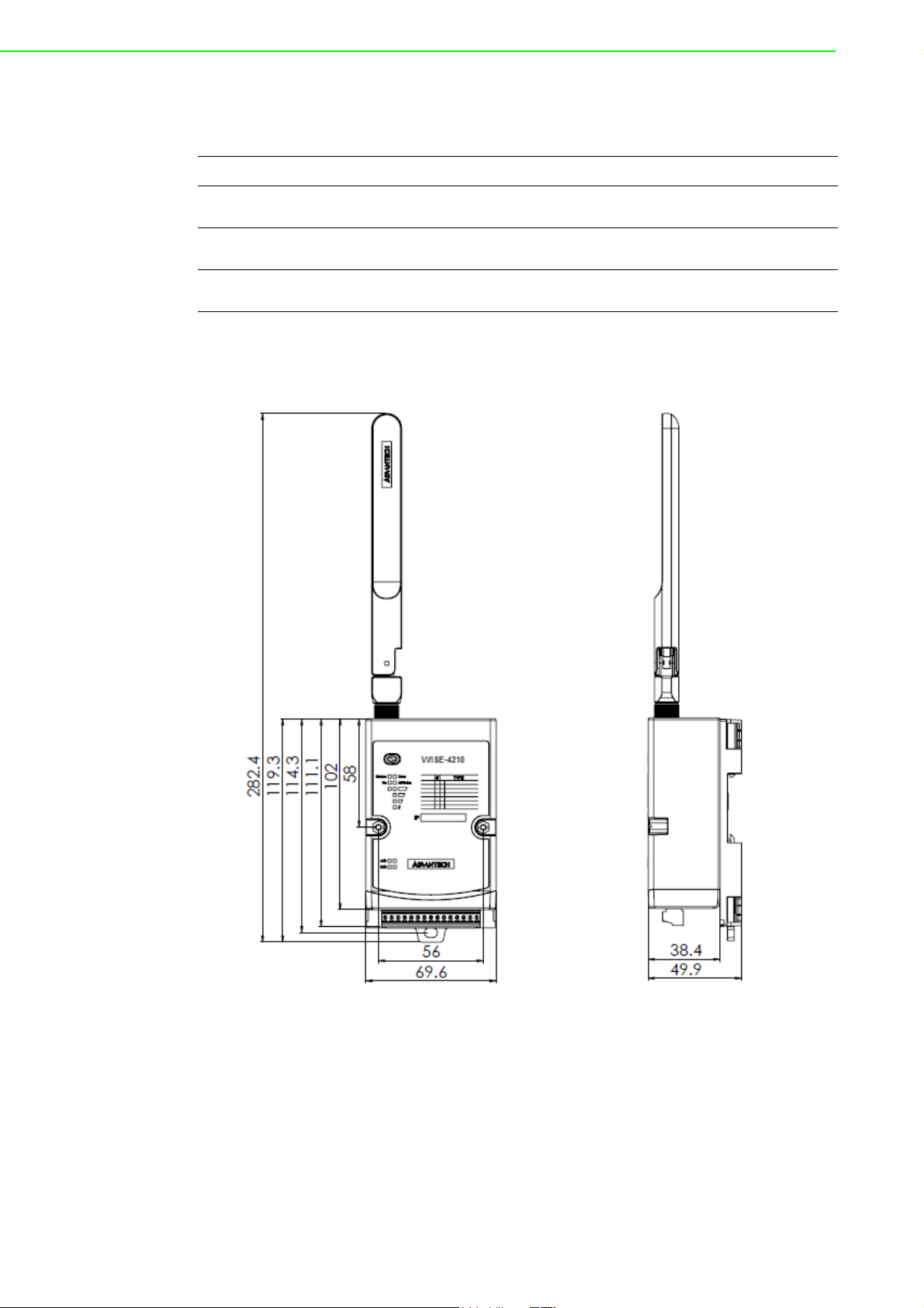
1.2 Mechanical Design and Dimensions
Figure 1.1 WISE-4210 Dimension Front & Side
WISE-4210 Series User Manual 2
Page 13

1.3 LED Definition
1.3.1 WISE-4210-AP
Chapter 1 Product Overview
Figure 1.2 WISE-4210-AP LED Indicator
LED Color Indication Behavior
Status Green Blink Operating normally
Error Red Blink I/O error or RF related error
Rx Green Blink Receiving data from LPWAN nodes
Figure 1.3 WISE-4210-AP LAN Port LED
3 WISE-4210 Series User Manual
Page 14
LED Color Indication Behavior
Link Green ON Both ends of devices are connected
Speed Yellow
1.3.2 WISE-4210-S231
ON 100 Mbps
OFF Less than 100 Mbps
Figure 1.4 WISE-4210-S231 LED Indicator
WISE-4210 Series User Manual 4
Page 15

LED Color Indication Behavior
Fast Blink
Status Green
Red
Red+Green
Error
Red+Green
Normal
Mode
*Automatically disable after 15 secs when battery power is used.
Rx Green NA NA
Tx Green Steady on
Signal Indicators/
Battery Level
Yellow
(2Hz)
Slow Blink
(0.5Hz)
Slow Blink
(0.5Hz)
Error fast
blinking+ Signal Indicator1
blinking
Error fast
blinking+ Signal Indicator2
blinking
On*4
On*3
On*2
On*1
All off
Initial Status
Push Status
Battery Voltage Low
RF related error
I/O related error
Sending data to Gateway (Push
Only)*
Battery Level:
80~100%
Battery Level:
60~80%
Battery Level:
40~60%
Battery Level:
20~40%
Battery Level
Lower than
20%
Chapter 1 Product Overview
Full Signal
Good Signal
Moderate Signal
Poor Signal
No Signal
5 WISE-4210 Series User Manual
Page 16

Status Green Steady on Site Survey Mode
Red
Red+Green
Error
Red+Green
Rx Green NA NA
Site
Survey
Mode
*Automatically disable after 15 secs when battery power is used.
OTA
Mode
Tx Green Steady on
Signal Indicators/
Battery Level
Signal Indicators/
Battery Level
Error
Rx Green Steady on OTA Rx Mode
Tx Green Steady on OTA Tx Mode
Signal Indicators/
Battery Level
Yellow
Yellow Stead on
Red
Red+Green
Red+Green
Yellow On*4
Slow Blink
(0.5Hz)
Error fast
blinking+ Signal Indicator1
blinking
Error fast
blinking+ Signal Indicator2
blinking
On*4
On*3
On*2
On*1
All off
Slow Blink
(0.5Hz)
Error fast
blinking+ Signal Indicator1
blinking
Error fast
blinking+ Signal Indicator2
blinking
On*3
On*2
On*1
All off
Battery Voltage Low
RF related error
I/O related error
Sending data to Gateway (Push
Only)*
Battery Level:
80~100%
Battery Level:
60~80%
Battery Level:
40~60%
Battery Level:
20~40%
Battery Level
Lower than
20%
Signal Indicators
Battery Voltage Low
RF related error
I/O related error
Battery Level:
80~100%
Battery Level:
60~80%
Battery Level:
40~60%
Battery Level:
20~40%
Battery Level
Lower than
20%
Full Signal
Good Signal
Moderate Signal
Poor Signal
No Signal
Full Signal
Good Signal
Moderate Signal
Poor Signal
No Signal
WISE-4210 Series User Manual 6
Page 17

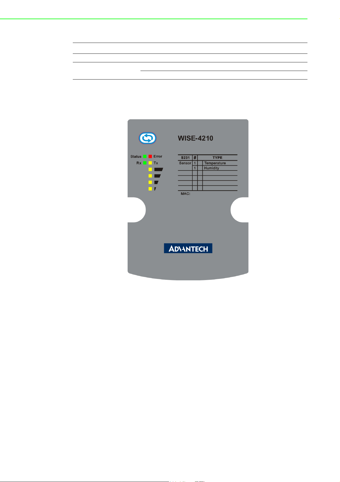
1.3.3 WISE-4210-S251
Chapter 1 Product Overview
Figure 1.5 WISE-4210-S251 LED Indicator
7 WISE-4210 Series User Manual
Page 18

LED Color Indication Behavior
Fast Blink
Status Green
Red
Red+Green
Error
Red+Green
Rx Green NA NA
Normal
Mode
*Automatically disable after 15 secs when battery power is used.
Tx Green Steady on
Signal Indicators/
Battery Level
Yellow
(2Hz)
Slow Blink
(0.5Hz)
Slow Blink
(0.5Hz)
Error fast blinking+ Signal
Indicator1
blinking
Error fast blinking+ Signal
Indicator2
blinking
On*4
On*3
On*2
On*1
All off
Initial Status
Push Status
Battery Voltage Low
RF related error
I/O related error
Sending data to Gateway
(Push Only)*
Battery
Level:
80~100%
Battery
Level:
60~80%
Battery
Level:
40~60%
Battery
Level:
20~40%
Battery Level
Lower than
20%
Full Signal
Good Signal
Moderate Signal
Poor Signal
No Signal
WISE-4210 Series User Manual 8
Page 19

Status Green Steady on Site Survey Mode
Red
Red+Green
Error
Red+Green
Rx Green NA NA
Tx Green Steady on
Site Survey
Mode
Signal Indicators/
Battery Level
Signal Indicators/
Battery Level
*Automatically disable after 15 secs when battery power is used.
Yellow
Yellow Stead on
Slow Blink
(0.5Hz)
Error fast blinking+ Signal
Indicator1
blinking
Error fast blinking+ Signal
Indicator2
blinking
On*4
On*3
On*2
On*1
All off
Battery Voltage Low
RF related error
I/O related error
Sending data to Gateway
(Push Only)*
Battery
Level:
80~100%
Battery
Level:
60~80%
Battery
Level:
40~60%
Battery
Level:
20~40%
Battery Level
Lower than
20%
Signal Indicators
Chapter 1 Product Overview
Full Signal
Good Signal
Moderate Signal
Poor Signal
No Signal
9 WISE-4210 Series User Manual
Page 20

OTA Mode
Red
Red+Green
Error
Red+Green
Rx Green Steady on OTA Rx Mode
Tx Green Steady on OTA Tx Mode
Yellow On*4
Signal Indicators/
Battery Level
Slow Blink
(0.5Hz)
Error fast blinking+ Signal
Indicator1
blinking
Error fast blinking+ Signal
Indicator2
blinking
On*3
On*2
On*1
All off
Battery Voltage Low
RF related error
I/O related error
Battery
Level:
80~100%
Battery
Level:
60~80%
Battery
Level:
40~60%
Battery
Level:
20~40%
Battery Level
Lower than
20%
Full Signal
Good Signal
Moderate Signal
Poor Signal
No Signal
1.4 Membrane Button
WISE-4210-Sxxx end nodes have one membrane button on name plate. This button
is design for switching different LED display mode or operation mode.
Note! WISE-4210-AP doesn't have membrane button, please use LAN port to
do further configuration.
WISE-4210 Series User Manual 10
Page 21

Chapter 1 Product Overview
Figure 1.6 WISE-4210 Membrane Button
Site
Normal Mode
Mode
Light Press
Behaviour
Long Press
*(LED indicator will go off automatically 15 secs later when using battery power.)
Power
Saving
Mode
LED turn
on→Get
battery
level→LE
D turn
off*
Leave
normal
mode
Nonpower
aving
Mode
Get battery level
Leave
normal
mode
Survey
Mode
Tx site
survey
packet
Leave
normal
mode
OTA Mode
Rx Status
Read battery level
Leave
OTA
mode
Tx Status
(by USB
port)
Tx Configuration
Tx Firmware
Low
Battery
NA
Leave
OTA
mode
Updat
e FW
fail
Reset
OTA
mode
NA
11 WISE-4210 Series User Manual
Page 22

1.5 Battery Power Switch
Open the rubber cover on the side of WISE-4210-Sxxx nodes, there is a battery
switch to turn on or turn off the battery power supply.
Note! This switch is only available for WISE-4210-Sxxx nodes, not for WISE-
4210-AP.
This switch only controls the power supply from batteries. It did not control the power supply of line power from terminal block.
Figure 1.7 WISE-4210 Battery Switch
1.6 Package Information
WISE-4210-APNA/UA
1 x WISE-4210-APNA/UA module
1 x Mounting bracket
1x China RoHS (UA series only)
WISE-4210-S231NA/UA
1 x WISE-4210-S231NA/UA module
1 x Mounting bracket
1x China RoHS (UA series only)
WISE-4210-S251NA/UA
1 x WISE-4210-S251NA/UA module
1 x Mounting bracket
1x China RoHS (UA series only)
WISE-4210 Series User Manual 12
Page 23

Note! AS923/EU868 version of WISE-4210 need to order antenna separately
1750008836-01 863-870MHz 2dBi Dipole Antenna for WISE-4210
1750008837-01 902-928MHz 2dBi Dipole Antenna for WISE-4210
Note! Battery needs to order separately
1760002647-01 3.6V/2500mAh AA Cylindrical Battery (non-
rechargeable)
Note! Micro-B USB cable for configuring WISE-4210-Sxxx nodes is available
for ordered:
1700023619-01 1M micro USB type-B male to USB type-A male
cable
Chapter 1 Product Overview
13 WISE-4210 Series User Manual
Page 24

WISE-4210 Series User Manual 14
Page 25

Chapter 2
2 General Specification
Page 26

2.1 General Specification
-- Transmit Power (CE): 14dBm±1dBm
-- Antenna Gain
902~928MHz:1.33 dBi
863~870MHz:2.19 dBi
2.1.1 Wireless Interface
IEEE Standard
– 625bps: IEEE 802.15.4g FSK Modulation
– 50kbps: IEEE 802.15.4g GFSK Modulation
Frequency Band
– 923MHz (920.60~924.60), BW: 400kHz
– 868MHz (865.00~869.00), BW: 400kHz
Data Rate: 625bps, 50kbps
Outdoor Range
– 625bps: 5 km with line of sight (with 2 dBi antenna)
– 50kbps: 2 km with line of sight (with 2 dBi antenna)
Transmit Power: +14dBm ±1dBm
Receiver Sensitivity: -100dBm
Topology: Star
Network Capacity: 64 end nodes (WISE-4210-S2xx)
Note! Outdoor Range is estimated with line of sight. The real transmitting dis-
tance would be affected by the environment of application site. Please
perform site survey to determine the set up range of wireless network.
2.1.2 General
I/O connector
– WISE-4210-AP: RJ-45 LAN port
3.5-mm spacing plug-in screw terminal block
– WISE-4210-S251: 3.5-mm spacing plug-in screw terminal block
Power connector:
– WISE-4210-AP: 3.5-mm spacing plug-in screw terminal block
– WISE-4210-S231: 3.5-mm spacing plug-in screw terminal block
– WISE-4210-S251: 3.5-mm spacing plug-in screw terminal block
Watchdog timer (WDT)
– System: 1.6 s
– Communication
– Programmable (FSV)
Real-time clock (RTC) accuracy: ±1 min/month
Enclosure: PC
Mounting: DIN 35 rail, wall, pole, and stack
Dimensions (W x H x D): 69 x 102 x 38 mm
Operation temperature: -25~70°C (-13~158°F)
Storage temperature: -40~85°C (-40~185°F)
Operating humidity: 10~95% RH (non-condensing)
Storage humidity: 0~95% RH (non-condensing)
WISE-4210 Series User Manual 16
Page 27

Note! Equipment will operate below 30% humidity. However, static electricity
Note! Measuring temperature and humidity will depend on sensor type.
2.1.3 Power
Chapter 2 General Specification
problems occur much more frequently at lower humidity levels. Make
sure you take adequate precautions when you touch the equipment.
Consider using ground straps, anti-static floor coverings, etc. if you use
the equipment in low humidity environments.
Whether the device is measuring temperature or humidity depends on
the settings of the sensors.
Power input voltage: 10 ~ 50 V
Power consumption (peak):
– WISE-4210-AP: 0.8 W @ 24 V
– WISE-4210-S231: 0.1 W @ 24 V
– WISE-4210-S251: 0.2 W @ 24 V
Battery socket (WISE-4210-Sxxx nodes only)
AA 3.6VDC battery x 3 (parallel connection)
Battery life (2400mAh battery x3) @ 25°C:
– 625bps: 5 years with 10 minute update rate
– 50kbps: 5 years with 1 minute update rate
Note! The battery life is estimated with 2400mAh battery, SB-AA11 by Vitzro-
cell Co.,Ltd.
Testing condition:
WISE-4210-S231: Temperature/Humidity sensor
WISE-4210-S251: Digital input only
DC
DC
DC
DC
Note! The battery life is estimated in the environment at 25°C. If the battery
2.1.4 Software
Utility: WISE Studio
Driver: ADAM .NET Class Library
WISE-4210-AP Protocols: TCP/IP, UDP, HTTP, HTTPS, DHCP, ARP, SNTP
WISE-4210-AP supports RESTful Web API .JSON format
operated in low temperature, the battery life would be lower. Here is the
estimation for battery SB-AA11 at different temperature:
SB-AA11 @ 0°C: Less than 30%
SB-AA11 @ -10°C: Less than 18%
SB-AA11 @ -25°C: Less than 13%
17 WISE-4210 Series User Manual
Page 28

2.1.5 Configuration Interface
WISE-4210-AP
Interface: LAN port
Connector: RJ-45
WISE-4210-Sxxx Nodes
Interface: USB virtual COM port
Connector: Micro-B USB
USB chipset: Silicon Labs CP210x
Driver: CP210x USB to UART Bridge VCP Drivers (https://www.silabs.com/
products/development-tools/software/usb-to-uart-bridge-vcp-drivers)
2.2 WISE-4210-AP
2.2.1 Uplink Communication Port
LAN port
Ethernet: IEEE 802.3u 10/100Base-T(X)
Connector: 1-port RJ-45
Protocol: Modbus/TCP, RESTful web API
RS-485 port
Signal: DATA+, DATA-
Connector: 3.5-mm spacing plug-in screw terminal block
Protocol: Modbus/RTU
2.2.2 Pin Assignment
Figure 2.1 WISE-4210-AP Pin Assignment
WISE-4210 Series User Manual 18
Page 29

2.2.3 Block Diagram
Chapter 2 General Specification
Figure 2.2 WISE-4210-AP Block Diagram
2.3 WISE-4210-S231
2.3.1 I/O Specifications
Temperature Sensor Input
Operating Range: -25°C ~ 70°C (-4°F ~ 157.9°F)
Data Resolution: 0.1 (°C/°F/K)
Accuracy: ±1.0°C (Vertical Installation)
Update Rate: Minimum 1 second
Response Time: 15 seconds (Achieving 63% of a step function)
Long Term Drift: 0.05°C/Year (0.09°F/Year)
Humidity Sensor Input
Operating Range: 10~90% RH
Resolution: 0.1% RH
Accuracy:
– ±4% for 0%~50% RH
– ±6% for 50%~60% RH
– ±10% for 60%~90% RH
Update Rate: Minimum 1 second
Response Time: 10 seconds (Achieving 63% of a step function)
Long Term Drift: 0.5% RH/Year
19 WISE-4210 Series User Manual
Page 30

2.3.2 Pin Assignment
Figure 2.3 WISE-4210-S231 Pin Assignment
2.3.3 Block Diagram
Figure 2.4 WISE-4210-S231 Block Diagram
2.4 WISE-4210-S251
2.4.1 I/O Specifications
Channels: 6
Logic level (dry contact)
– 0: Open
– 1: Close DI COM
Isolation: 3,000 Vrms
Supports 32-bit counter input function (maximum signal frequency, 3 kHz)
Supports keep/discard counter value on power-off
Supports frequency input function (maximum signal frequency, 3 kHz)
Supports inverted digital input status
WISE-4210 Series User Manual 20
Page 31

2.4.2 Pin Assignment
Figure 2.5 WISE-4210-S251 Pin Assignment
2.4.3 Block Diagram
Chapter 2 General Specification
Figure 2.6 WISE-4210-S251 Block Diagram
21 WISE-4210 Series User Manual
Page 32

2.4.4 Application Wiring
Figure 2.7 WISE-4210-S251 Digital Input Wiring Diagram
Figure 2.8 WISE-4210-S251 RS-485 Wiring Diagram
WISE-4210 Series User Manual 22
Page 33

Chapter 3
3 Hardware Installations
Page 34

3.1 Interface Introduction
3.2 Mounting
Like all WISE-4000 series modules, the WISE-4210 series of wireless sensor nodes
are designed as compact units. Applicable installation methods are briefly described
in the following sections.
Figure 3.1 WISE-4210 Interface Introduction
WISE-4210 Series User Manual 24
Page 35

Figure 3.2 WISE-4000 Series Mounting Kit Dimensions
3.2.1 DIN-Rail Mounting
Chapter 3 Hardware Installations
WISE-4470 modules can be fixed to a cabinet with mounting rails. Use a flathead
screwdriver to fasten the DIN rail adapter to your module. You can then use the end
brackets included in the package in order to keep it from sliding.
Figure 3.3 DIN Mounting Install
25 WISE-4210 Series User Manual
Page 36

Figure 3.4 DIN Mounting Front
Figure 3.5 DIN Mounting Back
WISE-4210 Series User Manual 26
Page 37

3.2.2 Wall Mounting
The plastic wall-mounting bracket that comes with the module can be used to mount
it on a wall, panel, or cabinet.
Chapter 3 Hardware Installations
Figure 3.6 Wall Mounting Install 1
27 WISE-4210 Series User Manual
Page 38

Figure 3.7 Wall Mounting Install 2
WISE-4210 Series User Manual 28
Page 39

3.2.3 Pole Mounting
Put the pole mounting ring through the middle hole of it. Note that you should unlock the
pole mounting ring with a screw driver before putting it through the device. Then mount
the WISE-4200 module steadily to the pole by locking the pole mounting ring tightly.
Chapter 3 Hardware Installations
Figure 3.8 Pole Mounting Front
29 WISE-4210 Series User Manual
Page 40

Figure 3.9 Pole Mounting Back
3.3 Wiring and Connections
This section provides basic information on wiring the power supply and I/O units.
3.3.1 Power Supply Wiring
WISE-4210 modules are designed to support a standard industrial unregulated 24V
power supply. For other applications, they can also accept +10 to +50 VDC input
DC
with 200 mV of peak-to-peak power ripple. The immediate ripple voltage should be
maintained between +10 and +50 V
are for the power supply wiring.
. The screw terminals labeled "+Vs" and "-Vs"
DC
Figure 3.10 WISE-4210-AP Power Wiring
WISE-4210 Series User Manual 30
Page 41

Figure 3.11 WISE-4210-S231 Power Wiring
Chapter 3 Hardware Installations
Figure 3.12 WISE-4210-S251 Power Wiring
3.3.2 Battery Installation
Open the battery cover on the back of module. There are 3 battery sockets for
3.6VDC AA batteries. Since the batteries are parallel connection, batteries are
installed in same direction, positive pole (+) on left and negative pole (-) on right.
Figure 3.13 WISE-4210 Battery Socket
31 WISE-4210 Series User Manual
Page 42

Open the rubber cover on the side of WISE module, there is a battery switch to turn
on or turn off the battery power supply.
Figure 3.14 WISE-4210 Battery Switch
Note! This switch is only available for WISE-4210-Sxxx nodes, not for WISE-
Note! Battery needs to order separately
3.3.3 I/O Units
WISE-4210 uses a plug-in screw terminal block for the interface between WISE-4210
and field devices. The following information is critical when connecting electrical
devices to I/O modules.
Use the correct wire gauge (note that the terminal block accepts wires from 0.5
to 2.5 mm)
Use a continuous length of wire (do not join separate wires to form a continuous
length)
Use the shortest wire length possible
Use wire trays for routing wherever possible
Avoid running wires near to high-energy wiring
Avoid running input wiring near output wiring
Avoid creating sharp bends or kinks in the wires
4210-AP.
1760002647-01 3.6V/2500mAh AA Cylindrical Battery (non-
rechargeable)
WISE-4210 Series User Manual 32
Page 43

Chapter 4
4 System Configuration
Page 44

4.1 Connection
4.1.1 WISE-4210-AP Connection
WISE-4210 uses RJ-45 LAN port for configuration. Connect your computer to Ethernet port of WISE module with RJ-45 cross-over Ethernet cable, and configure the IP
address of your computer as same IP domain as default IP address of module:
10.0.0.1
Figure 4.1 WISE-4210-AP LAN port
4.1.2 WISE-4210-Sxxx Node Connection
WISE-4210-Sxxx node use micro-B USB port for configuration. After remove the rubber cover on the side of WISE module, there is a micro-B connector. Connect this
port to computer's USB port for configuration. The USB driver would be need for creating virtual COM port of computer. Please refer to following link to get the latest USB
driver: CP210x USB to UART Bridge VCP Drivers (https://www.silabs.com/products/
development-tools/software/usb-to-uart-bridge-vcp-drivers)
Figure 4.2 USB configuration port of WISE-4210-Sxxx node
Note! Micro-B USB cable for configuring WISE-4210-Sxxx nodes is available
for ordered:
1700023619-01 1M micro USB type-B male to USB type-A male
cable
WISE-4210 Series User Manual 34
Page 45

4.2 Configuring WISE-4210-AP with Browser
4.2.1 System Requirements
The web utility of WISE-4210-AP is developed with public HTML 5, but for detailed
indication and data transmission mode, the type of web utility will depend on web
page of the operating system.
For mobile devices, the minimum system requirements of web browsers are as
below:
Safari 6 in Apple iOS
Web Browser in Google Android 4.0 (Ice Cream Sandwich)
Chrome in Google Android 4.0 (Ice Cream Sandwich)
Mobile Browser Chrome Android Safari
Configuration Y Y Y
File Upload N N N
Data Log Chart Y Y Y
Data Log Export N N N
For PC platforms, the minimum requirements of web browsers are as below:
Internet Explorer (version 11)
Google Chrome (version 30)
Mozilla Firefox (version 25)
Chapter 4 System Configuration
Mobile Browser Chrome Firefox Safari IE11 IE10
Configuration Y Y Y Y Y
File Upload Y Y N Y N
Data Log Chart Y Y Y Y Y
Data Log Export Y Y N N N
4.2.2 Factory Default Settings
IP Mode: Static IP Address
Default IP: 10.0.0.1
Subnet Mask: 255.0.0.0
Default Gateway: 0.0.0.0
IP Mode: Static
HTTP Port: 80
4.2.3 Module Authorization
Account Default Password Access Ability
root 00000000 All privileges
admin 00000000 All privileges except access control configuration
user 00000000
View module status only.
Not allow to change configurations
35 WISE-4210 Series User Manual
Page 46

Functions Account
root admin user
Device information View View View
Device setting Edit Edit Deny
System Restart Edit Edit Edit
Module Locate Edit Edit Edit
Change passwords Edit Deny Deny
Reset Password Edit Deny Deny
Reset to default Edit Deny Deny
Access control configurations Edit Edit Deny
Group configurations Edit Edit Deny
Download/upload processes Edit Edit Deny
Network configurations Edit Edit View
I/O configurations Edit Edit View
I/O statuses monitor View View View
Reset AI calibration to default Edit Deny Deny
MODBUS addresses Edit Edit View
Data log configuration and query Edit Edit View
Clear data log Edit Edit Deny
WISE-4210 Series User Manual 36
Page 47

Chapter 4 System Configuration
37 WISE-4210 Series User Manual
Page 48

www.advantech.com
Please verify specifications before quoting. This guide is intended for reference
purposes only.
All product specifications are subject to change without notice.
No part of this publication may be reproduced in any form or by any means,
electronic, photocopying, recording or otherwise, without prior written permission of the publisher.
All brand and product names are trademarks or registered trademarks of their
respective companies.
© Advantech Co., Ltd. 2018
 Loading...