

Page 1

User Manual
PWS-440
Computer
Page 2

About This Manual
Part No. XXXXXXXXXX Edition 1
Printed in Taiwan April 2013
This manual explains how to install, operate and maintain the PW S-440 Computer.
No part of this publication may be reproduced or used in any form, or by any electrical or mechanical means, without permission in writing from the manufacturer. This
includes electronic or mechanical means, such as photocopying, recording, or information storage and retrieval systems. The material in this manual is subject to
change without notice.
Advantech has many years experience in designing computers to meet severe environmental applications. These applications include those found by military as well as
industrial users. The PWS-440 has been designed to comply with the relevant
requirements of MIL-STD-810G, MIL-STD-461E and IP67. These include EMC, EMI,
temperature, Shock, vibration, humidity , dust and water. In addition the PWS-440 has
been developed to be reliable under all operational conditions that may be encountered by military services throughout the world.
© Copyright 2013 Advantech Co., Ltd. All rights reserved.
Bluetooth is a registered trademark of Bluetooth SIG.
Microsoft, Windows and ActiveSync are either registered trademarks or trademarks
of Microsoft Corporation.
Other product names mentioned in this manual may be trademarks or registered
trademarks of their respective companies and are hereby acknowledged.
Regulatory Compliance Statements
FCC Statement
This device complies with Part 15 of the FCC Rules. Operation is subject to the following two conditions:
(1) this device may not cause harmful interference, and
(2) this device must accept any interference received, including interference that may
cause undesired operation.
CAUTION! Exposure to Radio Frequency Radiation. The radiated output power of
this device is far below the FCC radio frequency exposure limits. Nevertheless, the
device shall be used in such a manner that the potential for human contact during
normal operation is minimized. When connecting an external antenna to the device,
the antenna shall be placed in such a manner to minimize the potential for human
contact during normal operation.
PWS-440 User Manual ii
Page 3

Federal Communications Commission Notice
This equipment has been tested and found to comply with the limits for a Class B digital device, pursuant to Part 15 of the FCC Rules. These limits are designed to provide reasonable protection against harmful interference in a residential installation.
This equipment generates, uses, and can radiate radio frequency energy.
If this equipment does cause harmful interference to radio or television reception,
which can be determined by turning the equipment off and on, the user is encouraged to try and correct the interference by one or more of the following measures:
Reorient or relocate the receiving antenna.
Increase the distance between the equipment and the receiver.
Connect the equipment to an outlet on a circuit different from that to which the
receiver is connected.
Consult the dealer or an experienced radio/TV technician for help.
The maximum SAR value reported is 0.082 => the SAR value to be define after SAR
test
Canada-Industry Canada (IC)
The wireless radio of this device complies with RSS 210 Industry Canada.
This Class B digital apparatus complies with Canadian ICES-003.
Cet appareil numérique de la classe B conforme á la norme NMB003du Canada.
Europe-European Union Notice
Radio products with the CE alert marking comply with the R&TTE Directive (1999/5/
EC) issued by the Commission of the European Community. Compliance with this
directive implies conformity to the following European Norms (in brackets are the
equivalent international standards).
EN 60950-1 (IEC60950-1) - Product Safety
EN 300 328 Technical requirement for radio equipment
ETS 301 489 General EMC requirements for radio equipment.
Products that contain the radio transmitter are labeled with CE alert marking and
may also carry the CE logo.
iii PWS-440 User Manual
Page 4

Safety
Use the following safety guidelines to help protect yourself and the PWS-440.
Do not attempt to service the PWS-440 yourself. Always follow installation
Be sure that nothing rests on the AC adapter's p ower cable and that the cable is
Do not cover the AC adapter with papers or other items that will reduce cooling;
Use only the AC adapter, power cord, and batteries that are approved for use
If you use an extension cable with the AC adapter, ensure that the total ampere
When you move the PWS-440 between environments with very different tem-
When you disconnect a cable, pull on its connector or on its strain relief loop,
instructions closely.
not located where it can be tripped over or stepped on.
also, do not use the AC adapter while it is inside a carrying case.
with this PWS-440. Use of another type of battery or AC adapter may cause risk
of fire or explosion.
rating of the products plugged in to the extension cable does not exceed the
ampere rating of the extension cable.
perature and/or humidity ranges, condensation may form on or within the PWS-
440. To avoid damaging the PWS-440, allow sufficient time for the moisture to
evaporate before using the PWS-440.
not on the cable itself. As you pull out the connector, keep it evenly aligned to
avoid bending any connector pins. Also, before you connect a cable make sure
both connectors are correctly oriented and aligned.
Battery Safety
There is a risk of explosion if the battery is replaced by an incorrect type.
Dispose of used batteries according to the instructions.
Do not dispose of batteries in a fire. They may explode. Check with local author-
ities for disposal instructions.
Notices
This unit is equipped with a battery pack and backup battery. It is possible that the
PDA may not power-on due to battery discharge as a result of storage.
In the above situation, insert the PDA into the cradle and connect the AC adapter.
Recharge the unit for 3 hours in order to fully charge its battery. The backup battery
will recharge from external power when the AC adapter is connected.
Battery charge notice
It is important to consider the environment temperature whenever you are charging
the Lithium-Ion battery pack. The process is most efficient at normal room temperature or slightly cooler. It is essential that you charge batteries within the stated range
of 0°C to 50°C. charging batteries outside of the specified range could damage the
batteries and shorten their charging life cycle.
Storage and safety notice
Although charged Lithium-Ion batteries may be left unused for several months, their
capacity may be depleted due to build up of internal resistance. If this happens they
will require recharging prior to use. Lithium-Ion batteries may be stored at temperatures between -20°C to 50°C, however they may be depleted more rapidly a t the high
end of this range. It is recommended to store batteries within normal room temperature ranges.
PWS-440 User Manual iv
Page 5

Contents
Chapter 1 Overview...............................................1
1.1 Introduction ............................................................................................... 2
1.1.1 Features........................................................................................2
Table 1.1: PWS-440 Computer Specification.......................... 2
1.1.2 Package Contents.........................................................................3
1.1.3 Optional Accessories.................................................................... 3
1.2 Familiarize with the PWS-440................................................................... 4
1.2.1 Front View . .......................................................................... ... .......4
1.2.2 Right View.................................................................... .................5
1.2.3 Bottom View........................................................... ... ... .... ... ..........6
1.2.4 Left View.......................................................................................6
1.2.5 Back View.....................................................................................7
1.2.6 Top View.......................................................................................7
1.3 4-In-1 Battery Charger (Optional)..............................................................8
1.4 Cradle (Optional).......................................................................................9
Chapter 2 Getting Started...................................11
2.1 Getting Started........................................................................................ 12
2.2 Connecting the PWS-440............ ............................................................ 12
2.2.1 Installing the battery....................................................................12
2.2.2 Charging the Battery...................................................................13
2.2.3 Charging the Battery with the Adapter Charger.......................... 14
2.2.4 Charging the Battery with the Cradle..........................................15
2.3 Powering up for the First Time................................................................16
2.4 Calibrating the touch screen ...................................................................16
2.5 Setting the Time and Date ......................................................................17
2.6 Adjusting the Screen Brightness.............................................................18
Chapter 3 Using the Hardware...........................19
3.1 Keypads and Function Buttons ...............................................................20
3.1.1 Entering Characters with the Keypad .........................................20
3.2 Using the Stylus ......................................................................................21
3.3 Inserting an Micro SD Memory Card....................................................... 22
3.4 Removing a Storage Card.......................................................................22
3.6 Connecting Devices to the PWS-440...................................................... 24
3.6.1 Connecting USB ............................................. .... ... ... ... ...............24
3.6.2 Connecting a Serial Device................. ... ... ... ...............................25
3.6.3 Connection to a LAN........................................................... ... ... .. 26
3.6.4 Connecting Headphones and a Microphone............................... 26
3.6.5 Connecting to the Cradle (Optional) ...................................... ... .. 26
Chapter 4 Getting Connected ............................29
4.1 Installing Microsoft ActiveSync................................................................30
4.1.1 Connecting to Your Computer .................................................... 30
4.2 Connecting with Bluetooth .................................... ... ... .... ........................32
4.3 Connecting to a WLAN (WiFi).................................................................34
4.3.1 Add a New Network....................................................................35
4.3.2 Connect to an Existing Network.................................................. 36
v PWS-440 User Manual
Page 6

4.4 Connecting GPS.....................................................................................37
4.5 COM Port list...........................................................................................41
Chapter 5 Advance Settings.............................. 43
5.1 Checking the Battery Status .......................................................... .... ... .. 44
5.2 Optimizing Battery Life............................................................................ 44
5.2.1 Changing the Automatic Power Settings.................................... 44
5.2.2 Adjusting Backlight Settings ....................................................... 45
5.3 Performing a System Reset.................................................................... 46
PWS-440 User Manual vi
Page 7

Chapter 1
1 Overview
Page 8

1.1 Introduction
Thank you for purchasing the PWS-440 Computer.
The PWS-440 is an ultra rugged computer designed to military standards. The
design incorporates the powerful Marvell PXA310 806MHz CPU with Microsoft Windows CE 6.0/ Embedded Handheld 6.5 operating system. The PWS-440 provides
the highest performance and reliability whilst minimizing the Total Cost of Ownership
(TCO). The PWS-440 incorporates a transflective LCD with touch-screen, keypad,
Wifi, and Bluetooth communication capability. Currently available options include
HSDPA (3.5G), and GPS.
To minimize the Total Cost of Ownership the PWS-440 is sealed to meet IP67 standards and complies with IEC 68-2-32 5 foot drop to concrete.
1.1.1 Features
The PWS-440 is a smart configurable handheld terminal which has been designed to
meet the requirements of a wide range of applications including:
Military & Law Enforcement
Industrial & Manufacturing
Emergency services and construction
PWS-440 been developed to comply with MIL-STD-461E, MIL-STD-810G and IP67
standards, the main specifications are as detailed below.
Table 1.1: PWS-440 Computer Specification
Items Description
OS Windows Embedded Handheld 6.5/ Windows CE 6.0
CPU Marvell PXA310 806 MHz
Memory
Display
Touch screen 4-wire Resistive touch screen
Audio System
Application Buttons
Communication
Status Indicator
256 MB SDRAM on board
1 GB Flash ROM on board
3.7” transflective TFT LCD, VGA resolution (640 x 480)/QVGA resolution (320 X 240)
AC-97, Internal microphone and one speaker ( stereo supported via
earphone jack)
One power on/suspend button
Navigation Key+ Function Key (4 function keys in front)
One HW reset key located right side door
One Button for backlight on/off (using power on/ suspend button)
802.11b/g WLAN module built-in with integral antenna
Bluetooth class 2, v2.1 built-in with integral antenna
GPS receiver module with antenna built-in internal module (for data
transmission only)
Power LED (two color LED x1) (at right side)
LED on the upper side for lighting usage
PWS-440 User Manual 2
Page 9

Table 1.1: PWS-440 Computer Specification
Two USB type A connectors, USB1.1 Host (** Two USB Type A at
Left Side)
One USB mini type B connector, USB1.1 Slave (at Right Side
Door)
I/O Ports
Main Battery
Power Adapter Universal AC 90V ~ 265V, 47~63Hz input, 12V, 3.5A output.
Physical 155 x 96 x 42mm, 650g
Environment
Rugged Specification IP67 5 ft drop to concrete MIL-STD-810G MIL-STD-461E
Certification CE, FCC, CCC
Accessories
One RS-232(full) One RS-232/422/485 (OPTION)
One RJ-45 for 10/100M ethernet (USB type)
One CF slot One stereo headphone jack
One microphone jack
One DC-In connector (At the right side)
One MicroSD Slot
Rechargeable Li-ion smart battery, 7.4V, 1880mAh, 2S1P,
59x38x25mm
Operating Temperature: -20 to +60°C
Storage Temperature -40 to +70°C
Charging Temperature 0 to +50°C
Operating Humidity 5% ~ 95% none condensing
1. Case: standard nylon (waterproof) case with belt loop;
2. elastic hand strap: prevent accidental drop
3. Stylus with tether kit
4. Power: DC-Adapter
12 V Vehicle charger with 12 V cable (option)
5. Cradle: 1 x RS-232, 2 x USB (1 x Type A; 1 x TypeB), 1 x DC-
in
6. 4-IN-1 battery charger
Chapter 1 Overview
1.1.2 Package Contents
The standard PWS-440 includes the following items:
PWS-440 Computer
Adapter
Battery
Stylus & string
Hand strap
1.1.3 Optional Accessories
In addition the following optional accessories may be included:
Cradle
4 IN 1 Battery Charger
Please carefully check the delivery documents to ensure that all items are present.
In the unlikely event of a discrepancy please contact your supplier.
3 PWS-440 User Manual
Page 10
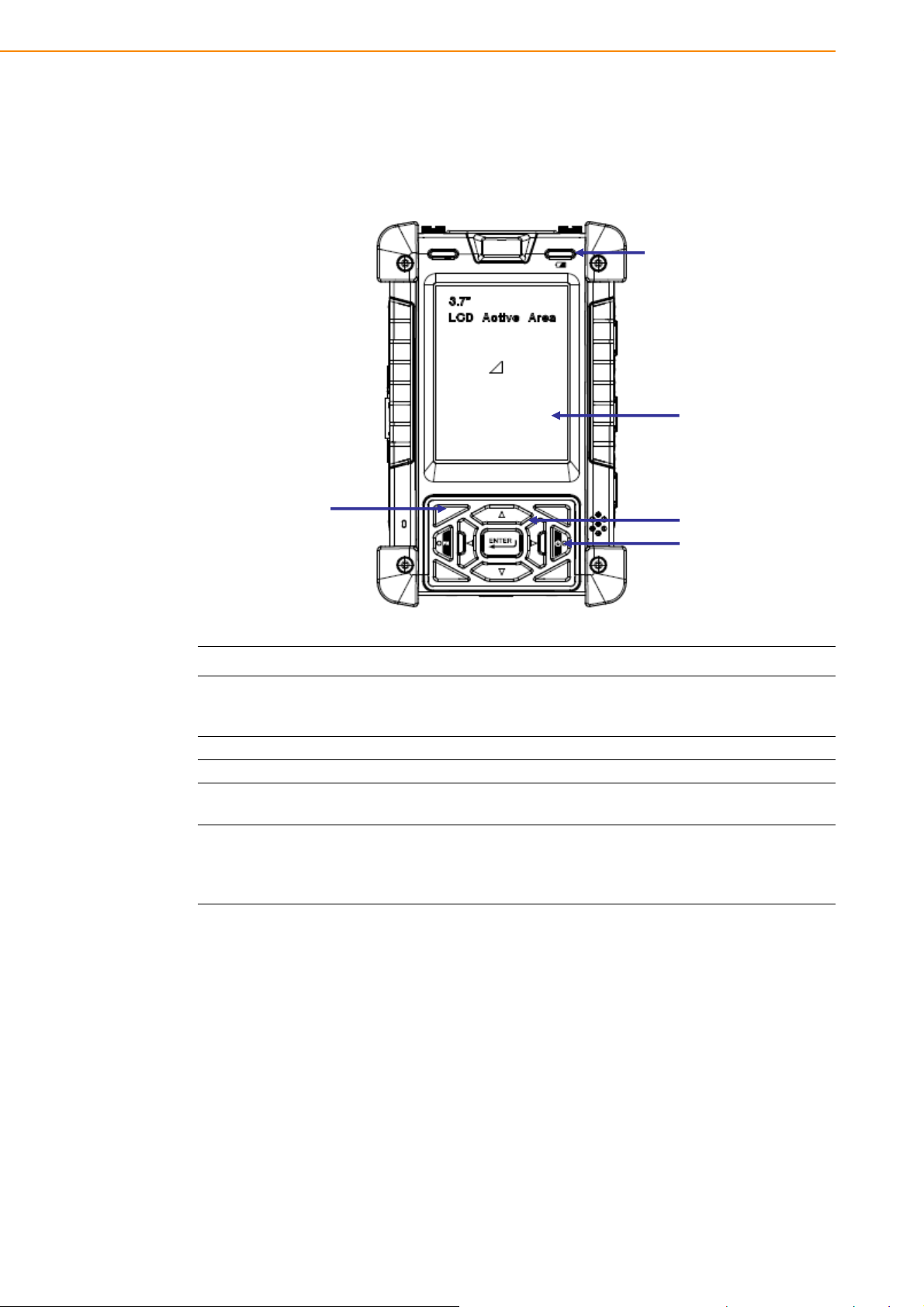
1.2 Familiarize with the PWS-440
Battery Light
Power LED
LCD Touch Screen
NavigĂƟŽn Keys
Power Button
Function Keys
The following sections describe the main components and features of the PWS-440.
1.2.1 Front View
Item Description
Displays the applications and data stored the PWS-440. It is a
LCD touch screen
Navigation Keys Press these keys to navigate in the PWS-440 interface.
Function Keys Programmable keypad interface for controlling the PWS-440.
Power button
Power LED
touch-sensitive screen and can be operated using the stylus or finger.
If the device is off, press this button to turn it on. When the unit is
on, press this button for 3 seconds to turn the PWS-440 of f.
Indicates the battery charging power status. Green -Battery is fully
charged or the device is running on battery power. When LED
flashes, the battery charge is at 13%. The battery should be
recharged immediately.
PWS-440 User Manual 4
Page 11

1.2.2 Right View
RJ45
Microphone Plug
Earphone Plug
USB mini B Port
DC IN
Micro SD Slot
HW Reset
Chapter 1 Overview
Item Description
RJ45 Port Connects to the LAN.
Earphone Plug
Microphone Plug Enables the recording of voice using an external microphone
USB mini type B port USB mini type B port (client).
Micro SD Slot Accommodates Micro Secure Digital memory cards.
HW Reset Switch Press the end of the stylus into the button to reset PWS-440.
DC IN Jack
Connects to audio line-out devices (earphones o r he adphones) for
use in noisy environments.
Connect the AC adapter to this jack to supply power to charge the
PWS-440 battery.
5 PWS-440 User Manual
Page 12

1.2.3 Bottom View
Cradle Connector
Battery Cover Latch
USB A Port
RS 232 Serial Port
RS 232 Serial Port
Item Description
Cradle connector
Battery Cover Latch
1.2.4 Left View
Connects the PWS-440 to cradle, enabling battery charging also
connects RS232, USBA and USB mini B).
Unlock the latch to open the battery compar tment cover to place or
remove battery.
PWS-440 User Manual 6
Item Description
RS 232 Serial Port
USB type A port Connects to USB type A port (host) to this port.
Connects using a mini 9 way D type connector for this port for
serial communications.
Page 13

1.2.5 Back View
Stylus
Chapter 1 Overview
Battery Compartment
Item Description
Stylus
Battery Compartment Houses the removable and rechargeable battery pack.
1.2.6 Top View
N/A
Item Description
N/A N/A
Enables you to interact with the operating system. Remove the stylus from the holder and hold and use it the same way you would a
pen or pencil. For use with the touch screen.
7 PWS-440 User Manual
Page 14

1.3 4-In-1 Battery Charger (Optional)
Battery Pack Holder Status LED
DC-IN Jack
Item Description
Battery Pack Holder Lock Battery pack into position for Battery charging.
DC IN Jack
Status LED
Connect the AC adapter to this jack to supply power to th e charger
and charge the PWS-440 Battery. *
Indicates that power and the PWS-440 battery is charging.
RED light - Battery is charging.
No Light - No battery fitted.
RED light Flash once - Power Adaptor connected, and ready for
charging battery.
Warning! * Both Battery charger adaptor and PWS-440 power adaptor are the
same, but they can NOT be interchanged with other adaptor.
PWS-440 User Manual 8
Page 15

1.4 Cradle (Optional)
Cradle Connector
Status LED
DC IN Jack
USB A Port USB B Port RS 232 Serial Port
Back Plate
Chapter 1 Overview
Item Description
Back Plate Supports the PWS-440 into charging position
RS 232 Serial Port Connects a serial cable.
USB type A port (host) Connects a USB type A (host) cable.
Cradle connector
USB mini type B port
(client)
DC IN Jack Connects the AC adapter to provide power for the cradle*
Status LED
Connects the PWS-440 to the cradle, Provides connections for
RS232, USB type A and mini USB type B.
Connects a USB mini type B (client) cable.
Indicates that power and the PWS-440 is charged.
Green light - PWS-440 is charging, and connecte d.
No Light - No PWS-440 fitted for charging.
9 PWS-440 User Manual
Page 16

PWS-440 User Manual 10
Page 17

Chapter 2
2 Getting Started
Page 18

2.1 Getting Started
This chapter explains how to install and charge the battery, how to check the battery
status, how to turn on the PWS-440, and how to calibrate the screen.
2.2 Connecting the PWS-440
2.2.1 Installing the battery
This part explains how to install the battery.
Warning! There is a risk of fire and burns if the battery pack is handled improperly.
DO NOT disassemble, crush, puncture, short external contacts, or dispose the battery pack in fire or water. DO NOT attempt to open or service the battery pack.
Dispose of used batteries according to local recycling guidelines in your
area. A backup battery cell is embedded into your device to prevent data
loss in instances when the removable battery pack is removed or completely discharged. This backup battery cell will only support the system
for a maximum of 3 minutes.
Status Charging Ready
*Amber flashing light *Amber light
Power OFF
*Amber flashing with Green light *Amber light
Power ON
PWS-440 User Manual 12
Page 19

1. Remove the battery compartment cover.
2. Align the battery contacts with the contacts in the compartment and place the
battery in the compartment as shown below.
Chapter 2 Getting Started
3. Replace the battery compartment cover, and lock the battery latch.
2.2.2 Charging the Battery
Before using the PWS-440 for the first time it will need charging for about 3 hours.
The PWS-440 can be charged using the power adaptor or the Cradle.
Note! When the battery power is below 10%, the PWS-440 will enter suspend
mode.
13 PWS-440 User Manual
Page 20

2.2.3 Charging the Battery with the Adapter Charger
1. Open the side door on the right bottom of the PWS-440.
2. Plug the adapter charger (B) into the side door (A).
3. Plug the power cord into the AC adapter (C).
4. Plug the AC adapter (D) into an electrical outlet.
PWS-440 User Manual 14
Page 21

2.2.4 Charging the Battery with the Cradle
1. Slide the PWS-440 into the cradle until it clicks into place.
2. Plug the AC adapter cable into the power connector on the cradle (A).
Chapter 2 Getting Started
3. Plug the power cable connector into the AC adapter (B), Plug the AC adapter
into an electrical outlet (C).
15 PWS-440 User Manual
Page 22

2.3 Powering up for the First Time
After you have charged the PWS-440 for about 3 hours the device is ready to be
used. You can now start up the PWS-440 when you can calibrate the touch screen,
practice with the stylus and set the date, time and zone. Turn on your device by
pressing the power button on the front panel.
2.4 Calibrating the touch screen
The calibration screen automatically appears when the unit is powered on for the first
time or after the system is reset.
1. Tap the center cross hair firmly and accurately with the stylus. The cross hair
moves to the next location.
2. Follow the cross hair and continue tapping until the screen has been calibrated.
PWS-440 User Manual 16
Page 23

3. After calibration is finished, press the Enter key to save the settings or press Esc
to revert to the previous settings.
Note! To recalibrate the screen at any time, tap Start -> Settings -> Control
Panel.Then double-tap Stylu s. Tap the Calibration tab, and tap Recali-
brate.
2.5 Setting the Time and Date
1. Tap Start -> Settings -> Control Panel.
Chapter 2 Getting Started
2. Double-tap Date/Time.
3. Tap the arrows next to the month to select the correct month.
4. Select a field in the time box and tap the arrows next to the time to change the
value of the field.
17 PWS-440 User Manual
Page 24

5. Tap the drop-down arrow next to Time Zone to select the correct time zone for
your area.
6. Check the box next to Automatically adjust... to have the OS automatically
update the time for daylight saving.
7. Tag Apply to save the settings.
2.6 Adjusting the Screen Brightness
1. Tap Start ->Settings -> Control Panel.
2. Double-tap OEMs Utility.
3. Click the Display Manager tab.
4. Under Backlight Control, click the Dark arrow to make the screen darker , or click
the Bright arrow to make the screen brighter.
5. Click OK to save and exit the utility.
PWS-440 User Manual 18
Page 25

Chapter 3
3 Using the Hardware
Page 26

3.1 Keypads and Function Buttons
The keypad enables you to both enter information and interact with the PWS-440
operating system.
3.1.1 Entering Characters with the Keypad
The operating system has an onscreen keyboard that enables you to enter alphanumeric characters with the stylus. Press the input panel icon in the system tray to
view the input panel menu. Tap Keyboard to view the onscreen keyboard.
Tap Hide Input Panel to close the keyboard.
The keyboard emulates a standard computer keyboard. Tap the onscreen keyboard
to enter, edit, and delete text.
PWS-440 User Manual 20
Page 27

3.2 Using the Stylus
Caution! Never use anything other than the PWS-440 stylus on the screen. Using
another object as a stylus could cause permanent damage. You can use
your finger to interact with the screen as well.
1. Remove the stylus from its holder.
2. Hold the stylus as you would a pencil.
3. To make a selection from a menu, lightly tap the tip of the stylus on that item.
Adjusting the Double-Tap Rate
Set the stylus double-tap rate as follows.
1. Tap Start ->Settings -> Control Panel.
2. Double-tap Stylus.
3. Tap the Double-Tap tab.
Chapter 3 Using the Hardware
4. Double-tap on the checkerboard graphic to set your double tap rate.
21 PWS-440 User Manual
Page 28

3.3 Inserting an Micro SD Memory Card
The PWS-440 has a SD card slot compatible with a wide range of Micro SD cards,
which are primarily used to back up or transfer files and data. The slot also supports
SDHC cards.
To insert a Micro SD card into the Micro SD slot.
1. Open the right centre door.
2. Insert the Micro SD card with the notched corner as oriented as shown below.
3. Press the card into the slot. The card is secure when it is flush with the slot.
4. Close and lock the door.
3.4 Removing a Storage Card
1. Open the right centre door.
2. Press the card in and release. The card pops out.
3. Remove the card from the slot.
4. Close and lock the door.
PWS-440 User Manual 22
Page 29

3.6 Connecting Devices to the PWS-440
This section describes how to connect devices to the PWS-440. Connection can be
made directly to the PWS-440 or using the cradle.
3.6.1 Connecting USB
The PWS-440 can accommodate both USB Type A and USB mini Type B.
Connecting a USB Type A
The illustration below shows how to connect a USB type A device to the PWS-440.
The connector can only go in one way. If it does not go in smoothly, check the orientation and try again.
PWS-440 User Manual 24
Page 30

Connecting a MINI USB Type B
The illustration below shows how to connect a mini USB type B cable to the PWS-
440.
The connector is keyed to only go in one way. If it does not go in smoothly, check the
orientation and try again.
Chapter 3 Using the Hardware
3.6.2 Connecting a Serial Device
Connect a serial device to the PWS-440 to perform serial communications.
Please see below illustration
25 PWS-440 User Manual
Page 31

3.6.3 Connection to a LAN
The PWS-440 is connected using a RJ-45 connector. See below:
3.6.4 Connecting Headphones and a Microphone
The PWS-440 utilizes an external microphone and speaker. A headset and microphone can be used in noisy environments. See the illustration above.
3.6.5 Connecting to the Cradle (Optional)
The cradle allows for charging the batteries as well as connecting USB and serial
devices.
PWS-440 User Manual 26
Page 32

Connecting USB
There is one USB Type A connector on the back which supports both USB keyboard
and mouse. In addition there is one Mini Type B USB port next to the Type A USB
connector. See the above illustration
Connecting a Serial Cable
A serial cable can be connected thePWS-440 cradle. See the above illustration
Chapter 3 Using the Hardware
27 PWS-440 User Manual
 Loading...