

Page 1

User Manual
EPD Control Board
EPD-132
Wireless ePaper Display Solution
Page 2

Copyright
The documentation and the software included with this product are copyrighted 2019
by Advantech Co., Ltd. All rights are reserved. Advantech Co., Ltd. reserves the right
to make improvements in the products described in this manual at any time without
notice. No part of this manual may be reproduced, copied, translated or transmitted
in any form or by any means without the prior written permission of Advantech Co.,
Ltd. Information provided in this manual is intended to be accurate and reliable. However, Advantech Co., Ltd. assumes no responsibility for its use, nor for any infringements of the rights of third parties, which may result from its use.
Acknowledgements
ARM is trademarks of ARM Corporation.
TI is trademarks of Texas Instruments Inc..
ITE is trademarks of ITE Tech Inc..
Eink is trademarks of E ink holding Inc..
Microsoft Windows are registered trademarks of Microsoft Corp.
All other product names or trademarks are properties of their respective owners.
Part No.2006013210 Edition 1
August 2019
EPD-132 Board User Manual ii
Page 3

Product Warranty (2 years)
Advantech warrants to you, the original purchaser, that each of its products will be
free from defects in materials and workmanship for two years from the date of purchase.
This warranty does not apply to any products which have been repaired or altered by
persons other than repair personnel authorized by Advantech, or which have been
subject to misuse, abuse, accident or improper installation. Advantech assumes no
liability under the terms of this warranty as a consequence of such events.
Because of Advantech’s high quality-control standards and rigorous testing, most of
our customers never need to use our repair service. If an Advantech product is defective, it will be repaired or replaced at no charge during the warranty period. For outof-warranty repairs, you will be billed according to the cost of replacement materials,
service time and freight. Please consult your dealer for more details.
If you think you have a defective product, follow these steps:
1. Collect all the information about the problem encountered. (For example, CPU
speed, Advantech products used, other hardware and software used, etc.) Note
anything abnormal and list any onscreen messages you get when the problem
occurs.
2. Call your dealer and describe the problem. Please have your manual, product,
and any helpful information readily available.
3. If your product is diagnosed as defective, obtain an RMA (return merchandize
authorization) number from your dealer. This allows us to process your return
more quickly.
4. Carefully pack the defective product, a fully-completed Repair and Replacement
Order Card and a photocopy proof of purchase date (such as your sales receipt)
in a shippable container. A product returned without proof of the purchase date
is not eligible for warranty service.
5. Write the RMA number visibly on the outside of the package and ship it prepaid
to your dealer.
iii EPD-132 Board User Manual
Page 4

Declaration of Conformity
FCC Class B
Note: This equipment has been tested and found to comply with the limits for a Class
B digital device, pursuant to part 15 of the FCC Rules. These limits are designed to
provide reasonable protection against harmful interference in a residential installation. This equipment generates, uses and can radiate radio frequency energy and, if
not installed and used in accordance with the instructions, may cause harmful interference to radio communications. However, there is no guarantee that interference
will not occur in a particular installation. If this equipment does cause harmful interference to radio or television reception, which can be determined by turning the equipment off and on, the user is encouraged to try to correct the interference by one or
more of the following measures:
Reorient or relocate the receiving antenna.
Increase the separation between the equipment and receiver.
Connect the equipment into an outlet on a circuit different from that to which the
receiver is connected.
Consult the dealer or an experienced radio/TV technician for help.
IMPORTANT NOTE:
FOR MOBILE DEVICE USAGE (>20cm/low power)
Radiation Exposure Statement:
This equipment complies with FCC radiation exposure limits set forth for an uncon-
trolled environment. This equipment should be installed and operated with minimum
distance 20cm between the radiator & your body.
FOR COUNTRY CODE SELECTION USAGE (WLAN DEVICES)
Note: The country code selection is for non-US model only and is not available to all
US model. Per FCC regulation, all Wi-Fi product marketed in US must fixed to US
operation channels only.
EPD-132 Board User Manual iv
Page 5

LABEL OF THE END PRODUCT: Host Model Name EPD-132R2
The final end product must be labeled in a visible area with the following " FCC ID:
M82-EPD-132-092 ".
If the labelling area is larger than the palm of the hand, then the following FCC part
15.19 statement has to also be available on the label: This device complies with Part
15 of FCC rules. Operation is subject to the following two conditions: (1) this device
may not cause harmful interference and (2) this device must accept any interference
received, including interference that may cause undesired operation.
OEM Integration Instructions:
This device is intended only for OEM integrators under the following conditions:
The module can be used to installation in other host. The antenna must be installed such
that 20 cm is maintained between the antenna and users, and the transmitter module may
not be colocated
with any other transmit or antenna. The module shall be only used with the integral
antenna(s) that has been originally tested and certified with this module.
As long as 3 conditions above are met, further transmitter test will not be required.
However, the OEM integrator is still responsible for testing their end-product for any
additional compliance requirement with this module installed (for example, digital device
emission, PC peripheral requirements, etc.)
NCC
低功率電波輻射性電機管理辦法
第十二條 經型式認證合格之低功率射頻電機,非經許可,公司、商號或使用者
均不得擅自變更頻率、加大功率或變更原設計之特性及功能。
第十四條 低功率射頻電機之使用不得影響飛航安全及干擾合法通信;經發現有
干擾現象時,應立即停用,並改善至無干擾時方得繼續使用。前項合法通信,指
依電信法規定作業之無線電通信。低功率射頻電機須忍受合法通信或工業、科學
及醫療用電波輻射性電機設備之干擾。
模組認證:
1. 本模組於取得認證後將依規定於模組本體標示審驗合格標籤。
2. 系統廠商應於平台上標示 「本產品內含射頻模組: XXXyyyLPDzzzz-x」
字樣。
Technical Support and Assistance
1. Visit the Advantech website at http://support.advantech.com where you can find
the latest information about the product.
2. Contact your distributor, sales representative, or Advantech's customer service
center for technical support if you need additional assistance. Please have the
following information ready before you call:
– Product name and serial number
– Description of your peripheral attachments
– Description of your software (operating system, version, application software,
etc.)
– A complete description of the problem
– The exact wording of any error messages
v EPD-132 Board User Manual
Page 6

Packing List
Before setting up the system, check that the items listed below are included and in
good condition. If any item does not accord with the table, please contact your dealer
immediately.
1 EPD-132 EPD control board & 13.3" EPD
Part No. Description
EPD-132B1AG-NSD01 13.3" Black/White ePaper Wi-Fi / BT display module solution in
2.4G
EPD-132R1AG-NSD01 13.3" Red/Black/White ePaper Wi-Fi / BT display module solution
in 2.4G
Page 7

EPD-132R1AG-NSD11 EPD-132R1AG-NSD01 for 50 pcs solution kit
EPD-132R1AG-NSD21 EPD-132R1AG-NSD01 for 100 pcs solution kit
EPD-132R1AG-NSD31 EPD-132R1AG-NSD01 for 500 pcs solution kit
EPD-132R1AG-NSD41 EPD-132R1AG-NSD01 for 1000 pcs solution kit
EPD-132B1AG-NSD11 EPD-132B1AG-NSD01 for 50 pcs solution kit
EPD-132B1AG-NSD21 EPD-132B1AG-NSD01 for 100 pcs solution kit
EPD-132B1AG-NSD31 EPD-132B1AG-NSD01 for 500 pcs solution kit
EPD-132B1AG-NSD41 EPD-132B1AG-NSD01 for 1000 pcs solution kit
Ordering Information
EPD-132 Board User Manual vi
Part No. Description
1750008001-01 Wi-Fi dipole antenna, 5dBi 2.4/5GHz
1750006043-01 RF SMA cable, L=150mm
1750008816-01 Antenna magnetic base, L=100mm
1700015038 FPC Cable 10P-0.5mm 7.9cm for DCU2.0
1700029192-01 60cm Micro USB with 5P(M) for power report
9696053RS00 EPD-053R A101-1 daughter board with Switch and LED
Page 8

Safety Instructions
1. Read these safety instructions carefully.
2. Keep this User Manual for later reference.
3. Disconnect this equipment from any AC outlet before cleaning. Use a damp
cloth. Do not use liquid or spray detergents for cleaning.
4. For plug-in equipment, the power outlet socket must be located near the equip-
ment and must be easily accessible.
5. Keep this equipment away from humidity.
6. Put this equipment on a reliable surface during installation. Dropping it or letting
it fall may cause damage.
7. The openings on the enclosure are for air convection. Protect the equipment
from overheating. DO NOT COVER THE OPENINGS.
8. Make sure the voltage of the power source is correct before connecting the
equipment to the power outlet.
9. Position the power cord so that people cannot step on it. Do not place anything
over the power cord.
10. All cautions and warnings on the equipment should be noted.
11. If the equipment is not used for a long time, disconnect it from the power source
to avoid damage by transient overvoltage.
12. Never pour any liquid into an opening. This may cause fire or electrical shock.
13. Never open the equipment. For safety reasons, the equipment should be
opened only by qualified service personnel.
14. If one of the following situations arises, get the equipment checked by service
personnel:
The power cord or plug is damaged.
Liquid has penetrated into the equipment.
The equipment has been exposed to moisture.
The equipment does not work well, or you cannot get it to work according to
the user's manual.
The equipment has been dropped and damaged.
The equipment has obvious signs of breakage.
DISCLAIMER: This set of instructions is given according to IEC 704-1. Advantech
disclaims all responsibility for the accuracy of any statements contained herein.
vii EPD-132 Board User Manual
Page 9

Consignes de Sécurité
1. Lisez attentivement ces instructions de sécurité.
2. Conservez ce manuel de l'utilisateur pour référence ultérieure.
3. Débranchez cet appareil de toute prise secteur avant le nettoyage Utilisez un
chiffon humide. N'utilisez pas de détergents liquides ni en spray pour le nettoyage
4. Pour les équipements enfichables, la prise de courant doit être située à proxim-
ité de l'équipement et doit être facilement accessible.
5. Gardez cet équipement à l'abri de l'humidité.
6. Placez cet équipement sur une surface fiable lors de son installation
7. Les ouvertures de l'enceinte sont destinées à la convection de l'air. Protégez le
matériel contre la surchauffe. NE COUVREZ PAS LES OUVERTURES.
8. Assurez-vous que la tension de la source d'alimentation est correcte avant de
connecter l'équipement à la prise de courant.
9. Placez le cordon d'alimentation de sorte que personne ne puisse marcher des-
sus. Ne placez aucun objet sur le cordon
10. Toutes les mises en garde et avertissements sur l'équipement doivent être
notés
11. Si l'équipement n'est pas utilisé pendant une longue période, débranchez-le de
la source d'alimentation pour éviter tout dommage d? à une surtension transitoire
12. Ne jamais verser de liquide dans une ouverture sous peine de provoquer un
incendie ou un choc électrique
13. Ne jamais ouvrir l'appareil.Pour des raisons de sécurité, cet équipement ne doit
être ouvert que par du personnel qualifié
14. Si l'une des situations suivantes se produit, faites vérifier l'équipement par le
personnel de service:
Le cordon d'alimentation ou la fiche est endommagé.
Un liquide a pénétré dans l'appareil.
L'équipement a été exposé à l'humidité.
L'équipement ne fonctionne pas bien ou vous ne pouvez pas le faire fonction-
ner conformément au manuel d'utilisation.
Equipment L'équipement est tombé et a été endommagé.
Equipment L'équipement présente des signes évidents de rupture.
AVERTISSEMENT: Cet ensemble d'instructions est donné conformément à la norme
CEI 704-1. Advantech décline toute responsabilité quant à l'exactitude des déclarations contenues dans le
EPD-132 Board User Manual viii
Page 10

Contents
Chapter 1 Introduction..........................................1
1.1 Introduction ...............................................................................................2
1.2 Specifications............................................................................................2
Figure 1.1 Block Diagram............................................................4
1.3 System implementation.............................................................................5
1.3.1 Advantech EPD-132 & ePaper Manager Solution........................5
Chapter 2 EPD Hardware Specification ..............7
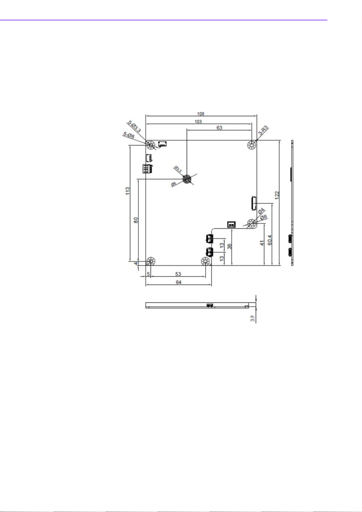
Figure 2.1 MODULE OUTLINE: 108 x 122 x 3.9 mm..................8
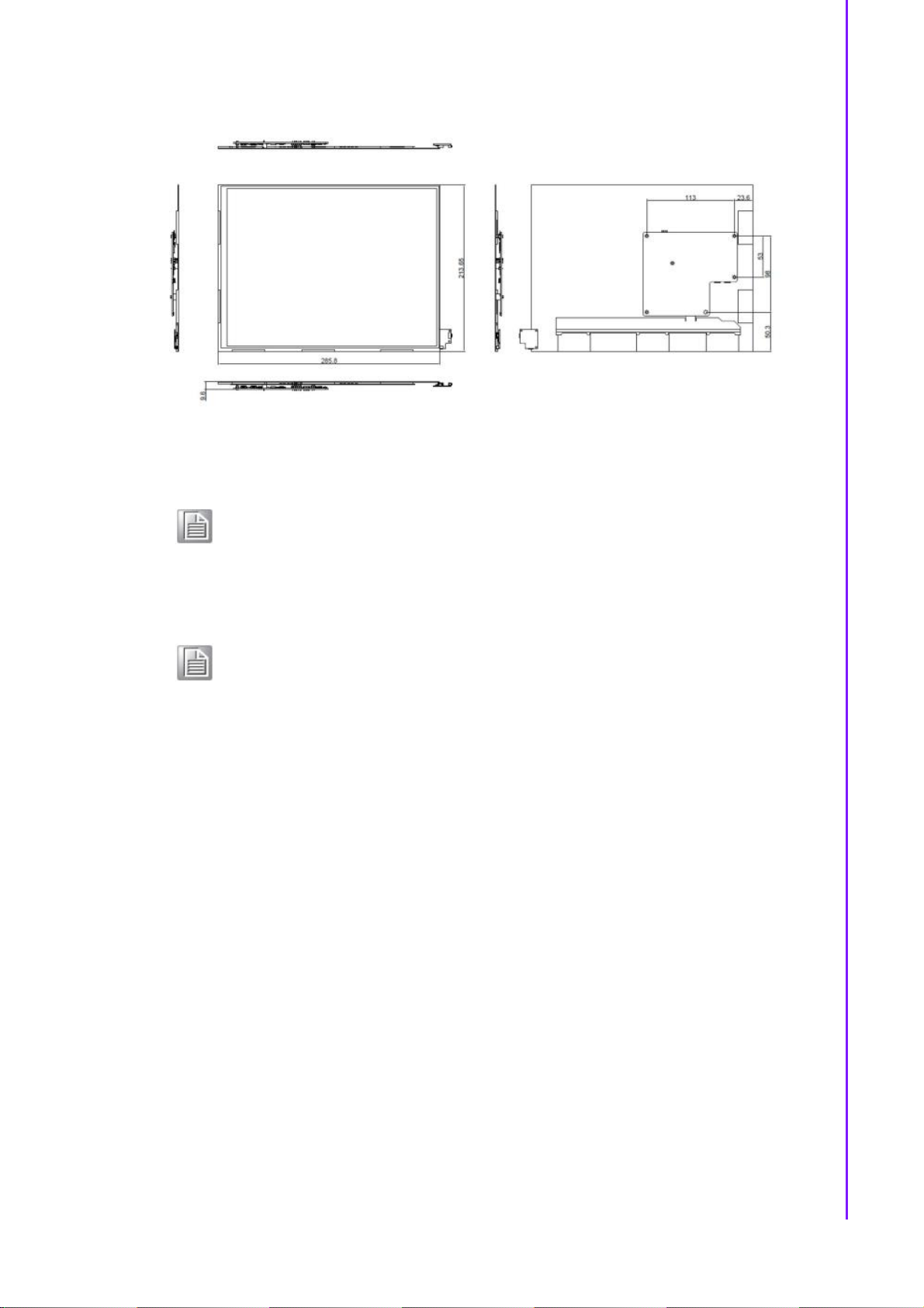
Figure 2.2 Module connect to panel Specifications.....................9
2.1 Board level I/O ........................................................................................10
Table 2.1: I/O Connector...........................................................10
2.1.1 CN2.............................................................................................11
Table 2.2: CN2 ..........................................................................12
2.1.2 CN3.............................................................................................12
Table 2.3: CN3 ..........................................................................13
2.1.3 CN8.............................................................................................13
Table 2.4: CN8 (SPI PIN HEADER)..........................................14
2.1.4 CN9.............................................................................................15
Table 2.5: CN9 ..........................................................................15
2.1.5 EPD connector............................................................................16
Table 2.6: EPD connector .........................................................17
2.1.6 Daughter Board Connector.........................................................18
Table 2.7: ALERT......................................................................18
Table 2.8: CON21......................................................................19
Table 2.9: SWTEST...................................................................19
Table 2.10:LED...........................................................................20
2.1.7 FFC_GPIO..................................................................................20
Table 2.11:FFC_GPIO................................................................21
2.1.8 DEBUG.......................................................................................22
Table 2.12:FFC_GPIO................................................................22
2.1.9 SWTEST.....................................................................................23
Table 2.13:SWTEST...................................................................23
2.1.10 PWR_ON1..................................................................................24
Table 2.14:SWTEST...................................................................24
2.1.11 Panel, PCBA connector and USB data transmission connector.25
2.2 Daughter board: LED & Button Behavior ................................................27
2.2.1 Button behaviors.........................................................................27
2.2.2 LED behaviors ............................................................................27
Chapter 3 EPD Network Architecture and
Software features29
3.1 System Topology Architecture ................................................................30
3.1.1 System environment...................................................................30
3.2 System Specification...............................................................................30
3.2.1 ePaper Manager.........................................................................30
3.2.2 WISE Gateway............................................................................31
3.2.3 EPD Device.................................................................................31
3.3 System Network Specification.................................................................31
ix EPD-132 Board User Manual
Page 11

Chapter 4 EPD-132 in ePaper Manager ............33
4.1 EPD-132 with ePaper Manager Solution................................................ 34
Table 4.1: ePaper manager main feature list............................ 34
4.2 Preparation ............................................................................................. 35
4.2.1 Hardware Component List.......................................................... 35
4.2.2 Software Component List ........................................................... 35
4.2.3 ePaper Manager Setup on ARK................................................. 35
4.2.4 WISE-3610W Setup and Connect to ARK with ePaper Manager...
50
4.2.5 EPD-132 Setup and Connect to ARK with ePaper Manager...... 52
4.2.6 Setup the Batch File WISE-3610W Installer............................... 57
4.2.7 Hands-on Batch File WISE-3610W Installer............................... 60
4.3 Hands-on EPD Device on ePaper Manager........................................... 62
4.3.1 ePaper Manager Login.............................................................. 63
4.3.2 Add Group & Device into ePaper Manager ................................ 64
4.3.3 Design Your Own Template........................................................ 71
4.3.4 Import Item Data to ePaper Manager......................................... 72
4.3.5 Combine the Template and Item Data........................................ 74
4.3.6 EPD Controller for EPD Device Management............................ 75
4.3.7 Final Association between EPD Device, Target Product and
Product Data............................................................................... 83
4.3.8 Smart Bus Stop Scenario ........................................................... 84
4.3.9 Clear Events and Data of MongoDB........................................... 84
4.4 Integrate EPD APIs into Your System .................................................... 92
4.4.1 EPD Data Update API ................................................................ 93
4.5 ePaper Manager Feature list .................................................................. 97
4.5.1 Component List........................................................................... 97
Chapter 5 WISE-EC EPD Design-in Service ...111
5.1 The Acquisition of Information .............................................................. 112
5.1.1 Design....................................................................................... 113
5.1.2 Integration................................................................................. 114
5.1.3 Production................................................................................. 114
5.2 Contact Information............................................................................... 115
5.3 Global Service Policy............................................................................ 115
5.3.1 Warranty Policy......................................................................... 115
5.3.2 Repair Process......................................................................... 116
EPD-132 Board User Manual x
Page 12

Introduction
Chapter 1
1
Page 13

1.1 Introduction
The EPD-132 is a module which supports the ultra-low power 2.4GHz RF wireless
protocol integrated with the 13.3" R/B/W & B/W EPD in an ARM Cortex-M4 processor. Users may use this kit to experience how wireless modules deliver images to ePaper and how e-Paper displays images. Users control our host mcu BM22 through
the Advantech ED22 development board.
The main features of EPD-132 is:
ARM Cortex-M4 Core Processor
Support IEEE 802.11b/g/n + Bluetooth 4.1 standard
13.3" e-Paper panel display
Rich control I/O: expansion pin header & I2C
Supports temperature 0 ~ 40 °C In R/B/W, 0 ~ 50 °C in B/W
Supports over-the-air upgrade (OTA)
Optional wall mount kit for various applications
1.2 Specifications
Computing MCUST 32-bit ARM Cortex-M4 Processor
EPD-132 Board User Manual 2
System Memory RAM 256 KB
Display
Storage
Wireless
Network
System
Interface
Screen Size 285.8 x 213.65 mm
Resolution 1600 x 1200 pixels
Internal
External
Standard IEEE 802.11b/g/n and BT4.1
Frequency
Band
Channels
Transmit
Power
Receiver
Sensitivity
Function End node
Antenna
connector
Antenna Dipole or PCB Antenna
Indicator But-
ton
ITE SPI Flash: 32Mb
BM22 SPI Flash: 128Mb
2.4000~2.4840 GHz for Wi-Fi
2.4000~2.4835 GHz for BT
1-11 for Wi-Fi
0~78 for BT 2.1+EDR
0~39 for BLE
Typ. 20.6 dBm at 802.11b CCK Mode 1M
Typ. 21.41 dBm at 802.11g OFDM Mode 54M
Typ. 21.46 dBm at 802.11n OFDM Mode MCS0
Typ. 5.49 for BT
Typ. -95dBm at 1 Mbps
Typ. -75 dBm at 54 Mbps
Typ. -89 dBm at MCS0
Typ. -89 dBm for BLE
MHF
1 for Reset/ Page Change/Wake-up/Alert cancel
Page 14

Chapter
1
Introduction
I2C 4pin Pin Header
FFC
Connector1
(Alert)
FFC
Connector2
(FFC_GPIO)
I/O (on-board) FFC
Connector3
(CN8)
Switch Factory mode setting
Micro USB
(CN2)
EPD connec-
tor
DC 5V
Power
Power
consumption
Operational
Temperature
Non-Opera-
Environment
Housing
Mechanical Dimension 240 x 322 x 60.5 mm/ 240 x 322 x 24 mm
Physical Characteristics
Operating
System
Note! The image for EPD need to follow below instruction.
tional Temp.
Assembly
Temperature
Operating
Humidity
Material Type Metal (NCT)
Painting Type SECC+ Painting
Weight 1.3kg
Dimensions
(W x H)
Weight
ThreadX v5.6
1. Image need to set as 1600*1200 pixels, do not resize it after com-
plete the image which will cause jaggy edges.
2. 24 bits / BMP format for EPD-132B
3. 24 bits / BMP format for EPD-132R and the color only support
below range.
Red: (255,0,0)
Black: (0,0,0)
White (255, 255, 255)
LED/button daughter board
10 port GPIO for system expansion
UART debug port
USB to TCON (Timing
Controller)
Interface for data to EPD
39P for 13.3" (R/B/W orB/W) & 9.7" EPD (R/B/W)
Micro USB (CN2) up to
0.9A/4.5 W in USB3.0 host
Micro USB (CN3) up to 2A/
10 W
Standby 18mA / 90mW,
Application 0.25A / 1.25W
In Data transmission mode With
Power supply
0 ~ 40 °C (R/B/W), 0 ~ 50 °C (B/W)
-25 ~ 60 °C (R/B/W), -25 ~ 70 °C (B/W)
10 ~ 40 °C
5 ~ 85% Relative Humidity, non-condensing
Panel: 285.8 x 213.65 mm
PCBA: 108 x 122 x 3.9 mm
Panel: 0.12g PCBA: 0.17g
3 EPD-132 Board User Manual
Page 15
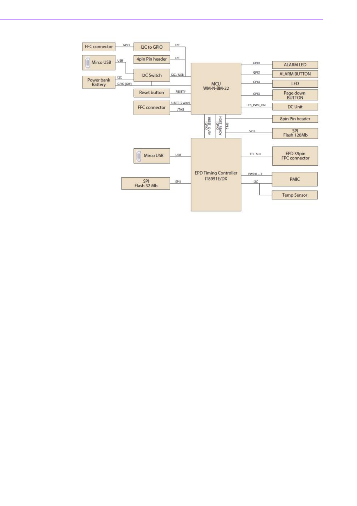
Figure 1.1 Block Diagram
EPD-132 Board User Manual 4
Page 16

Chapter
1
Introduction
1.3 System implementation
EPD device can be applied to different applications and the system integrator can
control the RESTful API for different scenarios.
1.3.1 Advantech EPD-132 & ePaper Manager Solution
Wireless EPD System consists of ePaper Manager, Gateway, Router and EPD
device.
The ePaper Manager provides Web GUI to management the wireless EPD
device.
The Gateway/embedded computer are responsible for communication between
ePaper Manager and EPD device.
The EPD is a device with ePaper, EPD controller and wireless connectivity.
Advantech provides a total solution. From the system architecture, EPD-132 is at the
end node of the system. Developers can apply Advantech WISE-3610W to connect
to the ePaper manager which is installed in Advantech Embedded Computer /
ARK2250L. There are multifunction RESTful API on ePaper Manager for developers
to integrate with vertical market applications eg. retail, smart warehouse, factory, hospitals and transportation.
5 EPD-132 Board User Manual
Page 17

EPD-132 Board User Manual 6
Page 18

EPD Hardware
Chapter 2
2
Specification
Page 19
This section provides board level PCBA and Panel mechanical size.
EPD-132 PCBA with following spec.
PCBA: 108 x 122 x 3.9 mm
PCB thickness: 3 mm ± 10%
Module input voltage: 5V DC-in
Connector current rating: 0.5A / Power contact
Figure 2.1 MODULE OUTLINE: 108 x 122 x 3.9 mm
13.3" EPD (PN:968AD00147/968AD00388) with following spec.
Panel Size: 285.8 x 213.65 mm
PN: 968AD00388 Operating temperature range: 0 °C to +50 °C for Black and
White,
PN: 968AD00147 Operating temperature range: 0 °C to +40 °C for Red, Black
and White.
All Eink Panel inspection criteria refer to Eink CAS & Inspection standard docu-
ment.
EPD-132 Board User Manual 8
Page 20
Chapter
2
EPD
Hardware
Specification
Figure 2.2 Module connect to panel Specifications
Note! E Ink Recommend condition for storage:
Temperature: 20 +-10 °C
Humidity: 60% RH+-10%RH, Non-condensing
Note! If the panel module has been put in low temperatured between 0~-25 °C
for a while, we recommend to leave it between 20 to 30 °C for 4 days
before assembly.
9 EPD-132 Board User Manual
Page 21
2.1 Board level I/O
EPD-132 Board User Manual 10
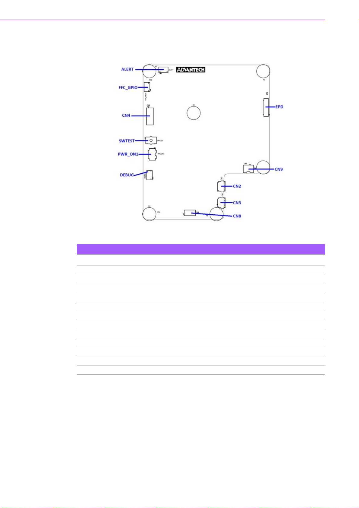
Table 2.1: I/O Connector
NAME Description EPD-132 EPD-130
CN2 External Micro USB Port v v
CN3 External Micro USB Port v v
CN4 10-pin header for ES test - CN8 8-pin header to connect to host - v
CN9 2-pin connector for DC-IN power - v
EPD 39-pin FPC to connect to e-paper panel v v
ALERT 10-pin FFC to connect to daughter board v FFC_GPIO 10-pin FFC connector for external GPIO v DEBUG 10-pin FFC connector v SWTEST For software test v v
PWR_ON1 4-pin DIP Switch v -
Legend: v = yes, - = no.
Page 22

Chapter
2
EPD
Hardware
Specification
2.1.1 CN2
11 EPD-132 Board User Manual
Page 23
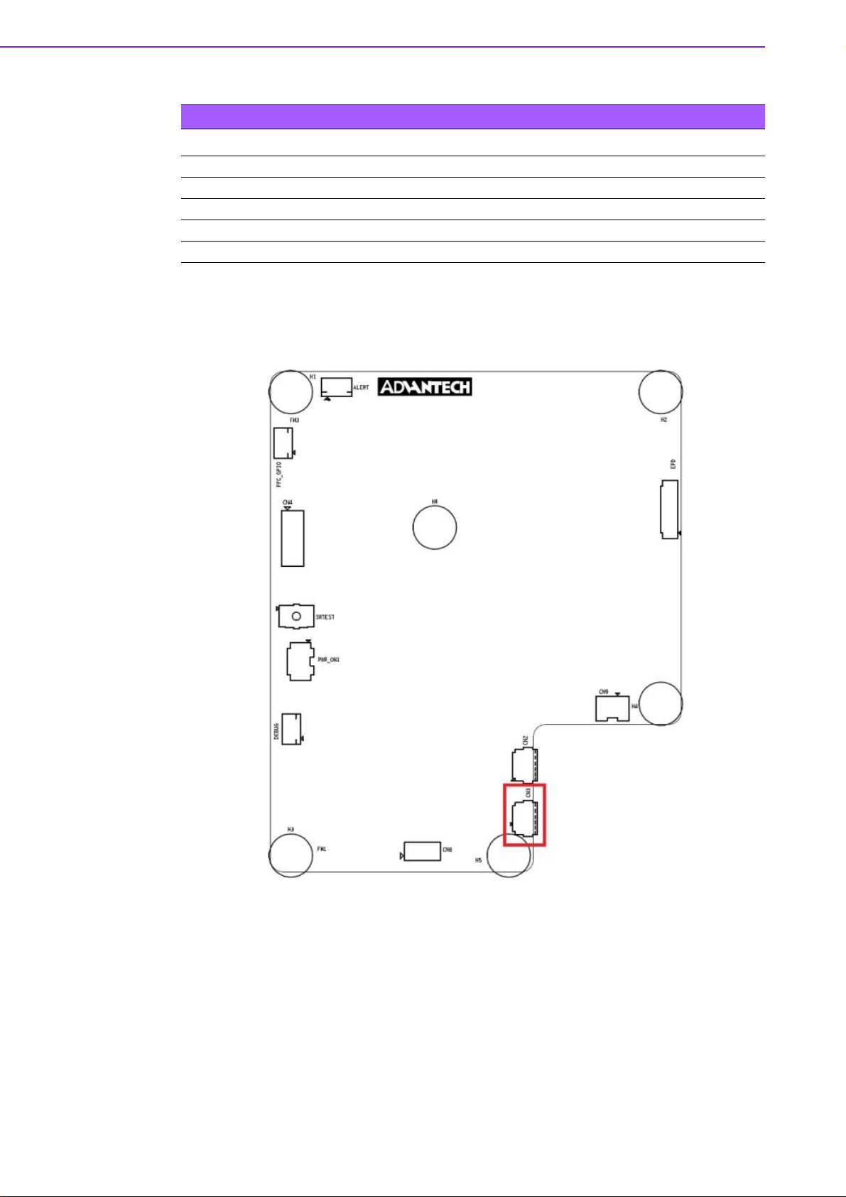
Table 2.2: CN2
PIN
1 +V5
2 USB_D3 USB_D+
4 GND
5 GND
PIN_NAME
2.1.2 CN3
EPD-132 Board User Manual 12
Page 24
Chapter
2
EPD
Hardware
Specification
Table 2.3: CN3
PIN
1 +V5
2 N/A
3 N/A
4 N/A
5 GND
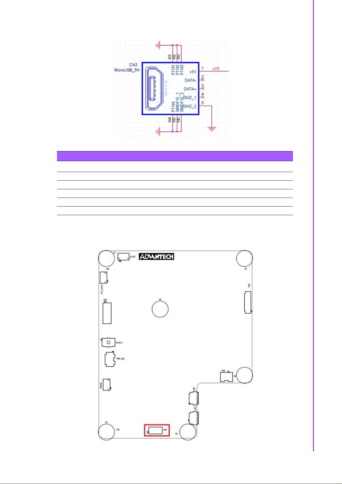
2.1.3 CN8
PIN_NAME
13 EPD-132 Board User Manual
Page 25

Table 2.4: CN8 (SPI PIN HEADER)
PIN PIN_NAME PIN PIN_NAME
1 NC 2 SPI_CLK(Serial Clock)
3 NC 4 SPI_MOSI(Master Output,Slave Input)
5 NC 6 SPI_MISO(Master Input,Slave Output)
7 NC 8 SPI_CS0#(Slave Selected)
Serial Clock:
SCLK: SCK
Master Output → Slave Input (MOSI):
SIMO, MTSR - correspond to MOSI on both master and slave devices, connects
to each other
SDI, DI, DIN, SI - on slave devices; connects to MOSI on master, or to below
connections
SDO, DO, DOUT, SO - on master devices; connects to MOSI on slave, or to
above connections
Master Input ← Slave Output (MISO):
SOMI, MRST - correspond to MISO on both master and slave devices, connects
to each other
SDO, DO, DOUT, SO - on slave devices; connects to MISO on master, or to
below connections
SDI, DI, DIN, SI - on master devices; connects to MISO on slave, or to above
connections
Slave Select:
SS: SS, SSEL, CS, CS, CE, nSS, /SS, SS#
In other words, MOSI (or SDO on a master) connects to MOSI (or SDI on a slave).
MISO (or SDI on a master) connects to MISO (or SDO on a slave). Slave Select is
the same functionality as chip select and is used instead of an addressing concept.
Pin names are always capitalized as in Slave Select, Serial Clock, and Master Output
Slave Input.
EPD-132 Board User Manual 14
Page 26
Chapter
2
EPD
Hardware
Specification
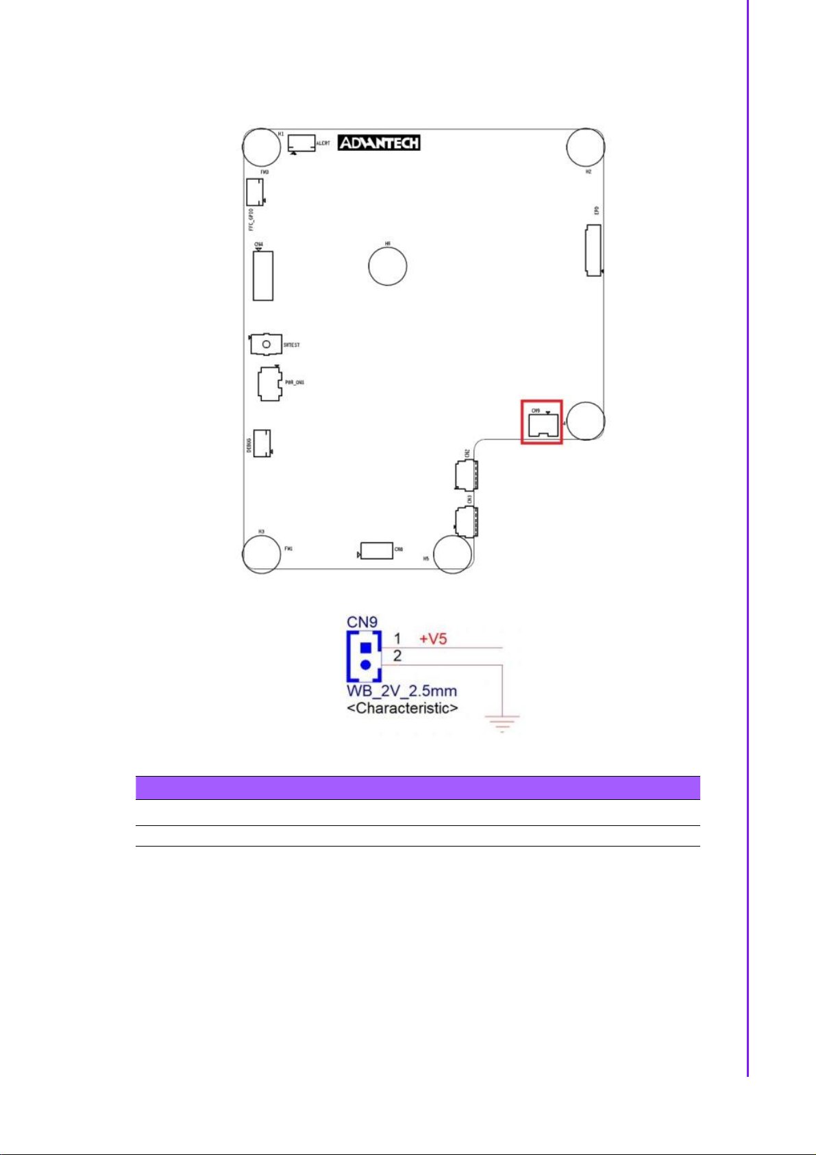
2.1.4 CN9
Table 2.5: CN9
PIN PIN_NAME PIN PIN_NAME
1 +V5 2 GND
15 EPD-132 Board User Manual
Page 27
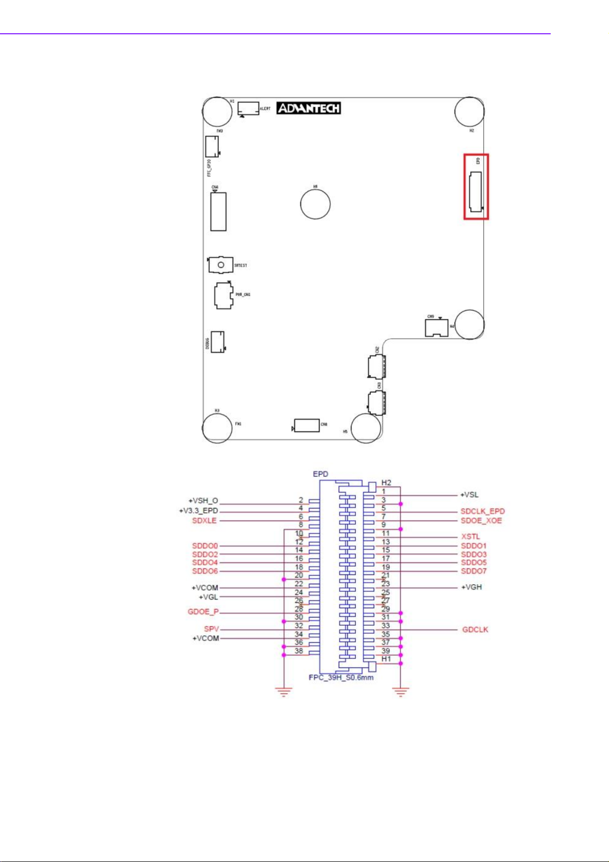
2.1.5 EPD connector
EPD-132 Board User Manual 16
Page 28

Chapter
2
EPD
Hardware
Specification
Table 2.6: EPD connector
PIN PIN_NAME PIN PIN_NAME
1 +VSL (Negative power supply
source driver)
3 GND 4 +V3.3_EPD (3.3V)
5 SDCLK_EPD (Clock source
driver)
7 SDOE_XOE (Output enable
source driver)
9 GND 10 NC
11 XSTL (Start pulse source driver) 12 SDDO0 (Data)
13 SDDO1 (Data) 14 SDDO2 (Data)
15 SDDO3 (Data) 16 SDDO4 (Data)
17 SDDO5 (Data) 18 SDDO6 (Data)
19 SDDO7 (Data) 20 GND
21 NC 22 +VCOM (Common connection)
23 +VGH (Positive power supply
gate driver)
25 NC 26 NC
27 NC 28 GDOE_P
29 GND 30 GND
31 GND 32 SPV (Start pulse gate driver)
33 GDCLK (Clock gate driver) 34 +VCOM (Common connection)
35 GND 36 GND
37 GND 38 GND
39 GND
2 +VSH_O (Positive power supply
source driver)
6 SDXLE (Latch enable source
driver)
8 GND
24 +VGL (Negative power supply
gate driver)
17 EPD-132 Board User Manual
Page 29
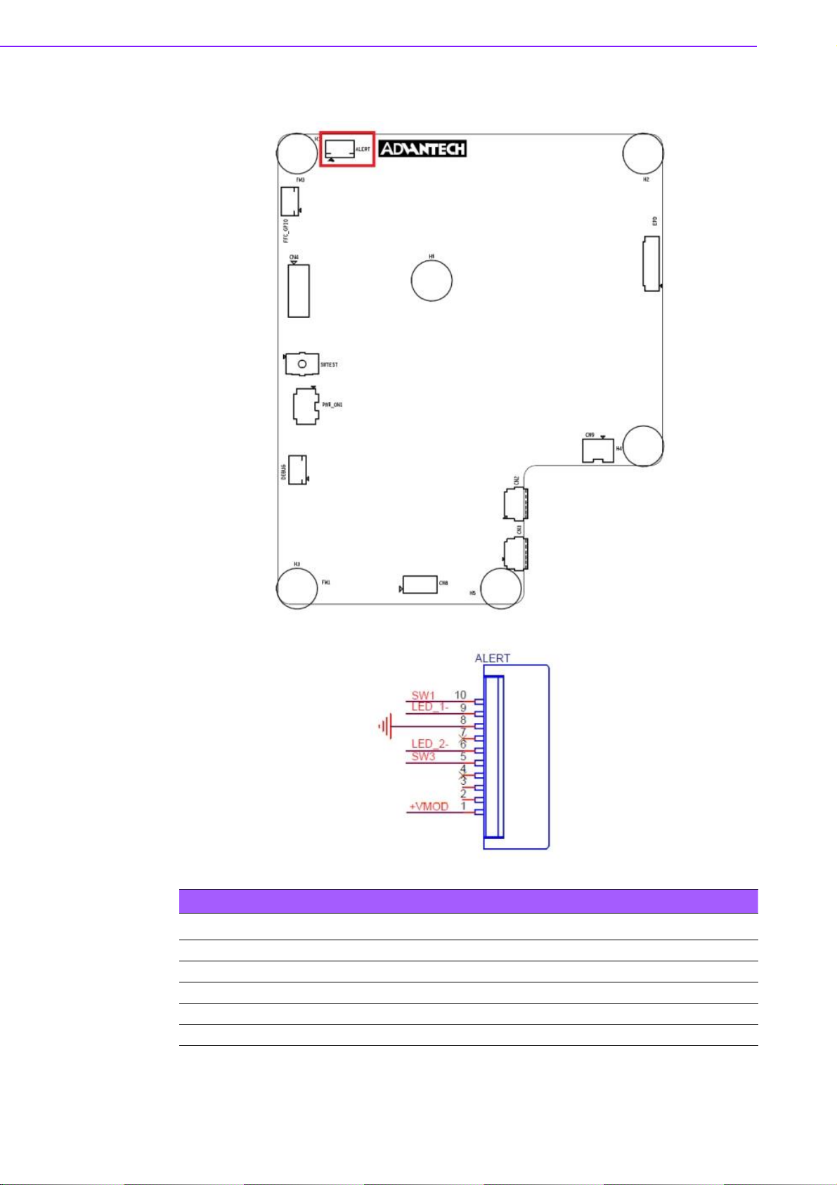
2.1.6 Daughter Board Connector
EPD-132 Board User Manual 18
Table 2.7: ALERT
PIN PIN_NAME PIN PIN_NAME
1 +VMOD 2 NC
3 NC 4 NC
5 SW3 6 LED_27 NC 8 GND
9 LED_1- 10 SW1
Page 30
Chapter
2
EPD
Hardware
Specification
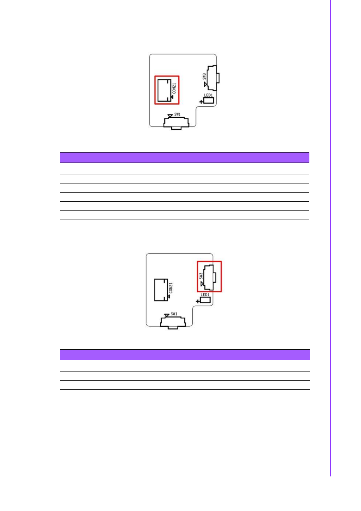
2.1.6.1 Daughter Board
Table 2.8: CON21
PIN PIN_NAME PIN PIN_NAME
1 SW1 2 LED_1 : Green
3 GND 4 NC
5 LED_2: Red 6 SW3
7 NC 8 NC
9 NC 10 +VDD
SW1 Un-mount, SW3 as below
Table 2.9: SWTEST
PIN PIN_NAME PIN PIN_NAME
1 +VDD 2 SW3
3 GND 4 GND
19 EPD-132 Board User Manual
Page 31

Table 2.10: LED
PIN PIN_NAME PIN PIN_NAME
1 +VDD 2 +VDD
3 LED_1- 4 LED_2-
2.1.7 FFC_GPIO
EPD-132 Board User Manual 20
Page 32

Chapter
2
EPD
Hardware
Specification
Table 2.11: FFC_GPIO
PIN PIN_NAME PIN PIN_NAME
1 +V3.3 2 GPIO_0 (default LOW)
3 GPIO_1 (default LOW) 4 GPIO_2 (default LOW)
5 GPIO_3 (default LOW) 6 GPIO_4 (default LOW)
7 GPIO_5 (default LOW) 8 GPIO_6 (default LOW)
9 GPIO_7 (default LOW) 10 GND
GPIO Voltage level is 3.3V
21 EPD-132 Board User Manual
Page 33

2.1.8 DEBUG
EPD-132 Board User Manual 22
Table 2.12: FFC_GPIO
PIN PIN_NAME PIN PIN_NAME
1 UART1_TX 2 UART1_RX
3 GND 4 JTAG_TDI
5 JTAG_TDO 6 JTAG_TCK
7 JTAG_TMS 8 JTAG_TRST
9 BOOT_0 10 +V3.3
Page 34

Chapter
2
EPD
Hardware
Specification
1. TDI (Test Data In)
2. TDO (Test Data Out)
3. TCK (Test Clock)
4. TMS (Test Mode Select)
5. TRST (Test Reset) optional.
2.1.9 SWTEST
Table 2.13: SWTEST
PIN PIN_NAME PIN PIN_NAME
1 GND 2 GND
3 SW_TEST# 4 SW_TEST#
5 GND 6 GND
23 EPD-132 Board User Manual
Page 35

2.1.10 PWR_ON1
Table 2.14: SWTEST
PIN PIN_NAME PIN PIN_NAME
1 NC: only for SW testing usage 2 NC: only for SW testing usage
3 EVK_MODE# 4 W_DISABLE: WiFi power on/off
OFF ON
1 NC NC
2 NC NC
3 BM22 mode EVK mode
4 WIFI power ON WIFI power OFF
EPD-132 Board User Manual 24
Page 36

Chapter
2
EPD
Hardware
Specification
2.1.11 Panel, PCBA connector and USB data transmission connector
1) Connected EPD FPC to mainboard
The FPC from the ePaper display
Release the rotary latch of the connector on the control board
Blend the FPC carefully to the control board direction
Insert the FPC into the connector on control board
25 EPD-132 Board User Manual
Page 37

After connecting firmly, lock the rotary latch.
Check if the connection is correct and tight.
Below Item 2: Connected Wi-Fi antenna to the mainboard
Below item 5: Connected IO daughter to the mainboard
Below item 6: Connected power cable to the mainboard USB (CN3)
EPD-132 Board User Manual 26
Page 38

Chapter
2
EPD
Hardware
Specification
2.2 Daughter board: LED & Button Behavior
The daughter board: 9696053RS00 can work with EPD-132.
2.2.1 Button behaviors
1. If RED LED (LED2) light up and click the button, system can turn off LED light
If no led light and click the button, the system screen can change to next page.
2. Press button then system will refresh image or restore default.
item Status Action Result
When LED2 is on Turn off LED2
1
When LED2 is off Change to next page image
2
When LED2 is off Press button for 10 sec
2.2.2 LED behaviors
1. Green LED (LED1) blink when system sends the image to display on panel.
2. Use LED command remote control from Tera Term.
item Status Action Result
1
2
Device connected
LED off
Step1. Device connected
LED off,
Step2.Remote
control command
from the gateway
Press button for 0.5 sec
and release button
System trigger to refresh
image
Command: Led 1 1:
Command: Led 1 0:
Command: Led 2 1:
Command: Led 2 0:
27 EPD-132 Board User Manual
Step 1.LED2 flash (0.5 sec toggle
LED2) after hold 5 sec.
Step 2. LED2 on and hold 10 sec
Step 3. LED2 off and then release
SW3 keys
Final result->Reset to default and
reboot
1. Turn on LED1 when image
refresh.
2. Turn off LED1 after image
refresh finish
green led
LED1 on
green led
LED1 light-off
red led
LED2 light-up
red led
LED2light-off
Page 39

EPD-132 Board User Manual 28
Page 40

EPD Network
Chapter 3
3
Architecture and
Software features
Page 41

3.1 System Topology Architecture
3.1.1 System environment
No Device1 OS version
1 ARK 2250L/ePaper man-
ager
2 WISE Gateway:
WISE3610W
6 EPD-132: Cypress BM22 ThreadX v5.6 , SDK 4.1.8 V1.0.0
WIN7, WIN10 (2019,Q3) 64 bit, Professional
OpenWRT R1.2.11 SW version: 3610W-
OIV0101-WifiEPD
3.2 System Specification
1. Each WISE-3610W gateway can organized an isolated network and be a Wi-Fi
AP as well.
2. Each WISE-3610W can support up to 100 EPD devices
3.2.1 ePaper Manager
Support friendly user interface to operate the execute command to control EPD-
132 (EPD device) and WISE-3610W(gateway).
External vertical system can operate the whole EPD system as below list:
1) ePaper manager GUI can perform command to control WISE-3610W (gateway).
2) ePaper manager can perform command to control EPD-132 (EPD device).
3) ePaper manager can deliver the image /Firmware EPD device through WISE
Gateway.
4) Device can periodical report status back to ePaper manager.
EPD-132 Board User Manual 30
Page 42

Chapter
3
EPD
Network
Architecture
and
Software
features
3.2.2 WISE Gateway
Receive commands from ePaper manager and execute.
Control EPD-132 through commands from ePaper manager.
EPD-132 wireless can connect to WISE-3610W directly.
EPD-132 wireless connects to Intranet AP, then WISE-3610W acts as a gate-
way to control EPD-132
Supports MQTT broker Server .
3.2.3 EPD Device
1. Supports BLE re-config : if device keeps failing to join, the device will enable
BLE for new SSID.
2. Supports emergency status report after join router. E.g. low power, HW malfunc-
tion and exception handling.
3. Support multi-image storage.
a.Full size image: 14 pages
b.Support partial updates. (ePaper Manager 2.0)
c.Supports de-compression in tag side. (ePaper Manager 2.0)
4. Supports Device actions from WISE-3610W.
3.3 System Network Specification
2-way communication: Device status report and battery status report.
Physical transmission data rate : 16Mbps Byte/Sec
Network join performance
1.1 pcs Tag join network in 6 secs.
2.100 pcs Tag join network in 1 minutes
Data transfer Performance from WISE-3610W
1) Update 50pcs EPD-132 in 30 mins
Note! The performance will be adjusted according to environmental limita-
tions.
31 EPD-132 Board User Manual
Page 43

EPD-132 Board User Manual 32
Page 44

EPD-132 in ePaper
Chapter 4
4
Manager
Page 45

4.1 EPD-132 with ePaper Manager Solution
Previously, we have go through EPD-132 function as an end device. To build up a
solution, we need a gateway to connect to our CMS: ePaper manager. Indeed, ePaper Manager provides complete solution to help you import tag data, design tag templates and manage tags easily. This user manual will show you how to build a total
solution system.
Moreover, ePaper Manager provides a complete solution to help you easily import
device data, design device templates, and manage devices. The main feature lists
are as below.
Table 4.1: ePaper manager main feature list
1 Overview System dashboard
2 EPD controller Control & Manage EPD device and association with
target
3 Item Data Group Management
4 Device list Target Product Data & Import
5 Template EPD image design and generation
6 White list setting EPD white list
7 OTA Firmware upgrade
8 Setting User account management
9 Document Online document
EPD-132 Board User Manual 34
Page 46

Chapter
4
EPD
-132
in ePaper
Manager
4.2 Preparation
4.2.1 Hardware Component List
1. Advantech Embedded Computer: ARK-2250L
2. Advantech IoT Gateway: WISE-3610W & Advantech EPD devices.
4.2.2 Software Component List
1. Window7 Professional version for ARK2250L
2. ePaper Manager Installation & License on ARK2250L
3. 500 connection License on ARK2250L.
4. Recommend Browser: Chrome version 75.0.3770.100 (official version) (64-bit)
5. Recommend FTP Server: FileZilla Server version 0.9.60 beta
4.2.3 ePaper Manager Setup on ARK
35 EPD-132 Board User Manual
Page 47

1. First, you will need to install ePaper manager on ARK-2250L.
ePaper Manager Installation
Double click the EPD ServerSetup_1.0.0.exe file to start installation process
on the server-side computer.
Follow the instructions in the setup wizard.
EPD-132 Board User Manual 36
Page 48

Chapter
4
EPD
-132
in ePaper
Manager
Windows hotfix of KB2999266 is required to run this software. Please download one
from Microsoft website and execute it. (https://www.microsoft.com/zh-TW/download/
confirmation.aspx?id=49093).
Microsoft Visual C++ 2015 Redistributable Update 3
(https://www.microsoft.com/en-us/download/details.aspx?id=53840)
Please click the next button if you no need to change the default installation path.
37 EPD-132 Board User Manual
Page 49

Please check your public IP or domain name and fill it in.
Please change the port number if need.
EPD-132 Board User Manual 38
Page 50

Chapter
4
EPD
-132
in ePaper
Manager
Please fill in the password and confirm password for PostgreSQL database.
Please fill in the password and confirm password for MongoDB database.
39 EPD-132 Board User Manual
Page 51

Please fill in the password and confirm password for root administrator to login the
server.
Please click the install button to start installation.
EPD-132 Board User Manual 40
Page 52

Chapter
4
EPD
-132
in ePaper
Manager
installing...
Please allow to access the installation of erl.exe.
41 EPD-132 Board User Manual
Page 53

Please allow to access the installation of epmd.exe.
Click the Finish button to exit the Setup Wizard.
2. You will get a register key from our sales package. You will need to enable the
key after installation of ePaper manager.
EPD-132 Board User Manual 42
Page 54

Chapter
4
EPD
-132
in ePaper
Manager
43 EPD-132 Board User Manual
Page 55

4.2.3.1 How to configure your FTP server
Before you start transmitting the image to the Electronic Paper Display (EPD) or
offering Firmware upgrades, you need to setup ARK2250L as an FTP server. Click
the startup icon to launch Filezilla.
1. Start configuring your FTP server.
2. Add user account.
EPD-132 Board User Manual 44
Page 56

Chapter
4
EPD
-132
in ePaper
Manager
45 EPD-132 Board User Manual
Page 57

3. Add password for user.
4. Add the shared folders and set the property of the directories and files. Add the
FTP Server to OTA Storage. You should make shure that the shared folders are
available.
EPD-132 Board User Manual 46
Page 58

Chapter
4
EPD
-132
in ePaper
Manager
5. Open Windows firewall setting and click allow a program or feature through Win-
dows firewall.
6. Make sure to allow FileZilla Server and FileZilla Server Interface to pass the
Windows firewall.
47 EPD-132 Board User Manual
Page 59

4.2.3.2 How to configure your FTP server on ePaper manager
1. Click Storage button to add a FTP storage for OTA and image delivery.
2. Click Add (+) button on the left-upper corner. Select the FTP option.
3. Finish the configuration form and click Confirm.
EPD-132 Board User Manual 48
Page 60

Chapter
4
EPD
-132
in ePaper
Manager
Storage Name: OTA
Security: NONE
Domain: [Your Server IP]
Port: 21
Account Name: [Your FTP account]
Password: [Your FTP password]
Root Path: [Your root path]
4. You will see an item in the Storage Management table.
5. Open up the FTP port of the firewall in the OS.
49 EPD-132 Board User Manual
Page 61

4.2.4 WISE-3610W Setup and Connect to ARK with ePaper Manager
After completing the ePaper manager installation, start configuring the Gateway:
WISE-3610W.
1. Power on WISE-3610W.
2. Open WISE-3610W management web page: Open a web browser (Chrome is
suggested) and enter the IP Address http://192.168.1.1 or http://advantech.local/
3. Login: The default user name and password are root and ePaper. Click the
Login button to open the web-based configuration page.
4. Build networking connection.
EPD-132 Board User Manual 50
Page 62

Chapter
4
EPD
-132
in ePaper
Manager
5. Ethernet WAN Backhaul Connection:
Connect an Ethernet cable to exiting backhaul router and ISP cable modem or
Internet service provider xDSL / FTTx modem.
Select WAN for NorthBond backhaul connection and choose Protocol > DHCP
Client
51 EPD-132 Board User Manual
Page 63

6. Setup the ePaper management server IP as shown below.
4.2.5 EPD-132 Setup and Connect to ARK with ePaper Manager
This explains how the router joins with the WISE-3610W (gateway). Users can
understand what performance can be reached using our specification. The user can
also change some parameters to fit their requirements.
EPD-132 Board User Manual 52
Page 64

Chapter
4
EPD
-132
in ePaper
Manager
1. Default WISE-3610W setting:
a. SSID: ADV-ePaper
2. Password: ePaperePaper
b. WISE-3610w login as shown below (root/ePaper)
3. Power on EPD-132
a. Plug the Micro USB to provide the power.
4. EPD-132 join the network with SSID:
a. Setup the SSID to join the network with APP in one device, refer to Chapter
4.3.
53 EPD-132 Board User Manual
Page 65

Note! 1. The default SSID on WISE-3610W & EPD-132 will be the following:
SSID: ADV-ePaper, Password: ePaperePaper
2. Once WISE-3610W & EPD-132 powers on with the default SSID/
Password setting, EPD-132 will connect to WISE-3610W. EPD-132
will set the default Agent IP according to the Domain from gateway after connection.
3. EPD-132 may have changed the default SSID/Password in some
cases and lost the connection with the gateway. Users need to
maintain the EPD setting list in WISE-3610W before using the BLE
tool to re-config the EPD-132's SSID/Password.
4. EPD-132 connects to ePaper manager of the ARK2250L through
WISE-3610W's Agent. So we need to setup the Gateway's IP
where the Agent is on EPD setting page, and EPD-132 can connect to the Agent via customer’s AP router.
5. In summary, if EPD-132 only needs to change SSID/Password,
users can use the BLE tool. If EPD-132 needs to setup the Agent
IP connect to ePaper manager of ARK2250L, users need to use
the tool on WISE-3610W refer to #4.2.6. with WISE-3610W/EPD132 default setting: SSID: ADV -ePaper, Password: ePaperePaper.
Configure Wi-fi setting through BLE
BLE-WiFi introducer service is a demonstration to setup SSID and password to join a
network by smart phone. EPD-132 will be paired via a BLE GATT server with the
smartphone.Then you can start your Wi-Fi security setting.
Step 1: Install and launch the BLE Scanner app on iOS or Android.
EPD-132 Board User Manual 54
Page 66

Chapter
4
EPD
-132
in ePaper
Manager
Step 2: Pull down the screen to rescan devices and it will list nearby BLE devices.
Find the "WiFiInt" device and press the CONNECT button.
Step 3: If the connection is successful, you can see the picture below. Press the
"CUSTOM SERVICE" button.
Note! You need to remove bluetooth pairing with "WiFiInt" from bluetooth set-
ting when you can not connect to a device.
55 EPD-132 Board User Manual
Page 67

Step 4: Find the UUID: ACA0EF7C-EEAA-48AD-9508-19A6F6B356 for SSID characteristic.
Step 5: Find the UUID: 40B7DE33-93E4-4C8B-A876-D833B415A6CE for Password
characteristics then procedure as Step4.
EPD-132 Board User Manual 56
Page 68

Chapter
4
EPD
-132
in ePaper
Manager
b. Setup the batch file WISE-3610W installer
i. See chapter 4.2.6
4) EPD-132 will report status every 1 mins (adjustable)
4.2.6 Setup the Batch File WISE-3610W Installer
1) EPD Connection Setting
EPD Connection Setting feature is for users to wirelessly setup the group EPD SSID/
Password/IP and connect to a dedicated Router /gateway.
There are two functions: "EPD setting" and "EPD Import" in EPD Connection Setting
as shown below. "EPD setting" is the setting feature for each EPD manually. "EPD
Import" is the feature to import a batch file for the system to setup the EPD group
automatically.
In EPD setting, users can add EPD node one by one in this page. EPD Setting as
shown below.
57 EPD-132 Board User Manual
Page 69

2) EPD Setting
Below shows the EPD device information, including EPD device's Mac address,
router SSID/password and Gateway IP. Though the default values are the same as
below, the system offers four operations add node/edit/delete/reload settings as
shown below.
a. "Add EPD Node” button: Turns to general setting page as shown below. Users
should see four written parameters.
i. EPD Mac address: Users can find Mac address on the sticker label on EPD
node and Mac address is a string A to F, 0-9 and string length is 12 byte.
ii. AP SSID: SSID is the user's AP router.
iii. AP Password: Password is defined on the user's AP router and string length
is more than 8 bytes.
iv. Gateway IP: This gateway IP is the 3610W WAN port IP address. Users can
find this information on web page of Status->overview.
b. Button "Edit" : It return to general setting page to modify these settings.
c. Button "delete": The setting Items of the EPD are deleted directly after clicking the
button.
d. Button "Reload Setting" : All EPD settings must choose the "Reload Setting" button
for the system to apply it.
EPD-132 Board User Manual 58
Page 70

Chapter
4
EPD
-132
in ePaper
Manager
3) EPD import
1. When multiple EPD devices need to be added into the EPD list, users can import
a batch file to set it up. The file format can reference the template Node.json on the
web page as shown below.
As shown in the red box below, EPD nodes have four attributes representing EPD
Mac address, AP SSID, AP password and gateway IP address respectively, and
users should follow the format below .
59 EPD-132 Board User Manual
Page 71

2. If the file uploads successfully, EPD device information is shown on screen. If the
information does not display on the web page , please check file content for any error
symbols.
After importing files, users should click "Reload setting" to let the system apply it.
4.2.7 Hands-on Batch File WISE-3610W Installer
1) EPD Setting
Installer SOP. Follow these 3 steps
Step 01: click "EPD Connection Setting" ->" EPD Setting"-> "Add EPD Node "on web
page
Step 02: Fill in the corresponding information of the EPD Mac address, AP SSID, AP
Password, Gateway IP then save & apply.
EPD-132 Board User Manual 60
Page 72

Chapter
4
EPD
-132
in ePaper
Manager
Step 03: Click Reload setting button
2) EDP import
Installer SOP. Follow these 2 steps to import the file.
Step 01: Click "EPD import"->choose file->Append
61 EPD-132 Board User Manual
Page 73

Step 02: Click Reload setting button
4.3 Hands-on EPD Device on ePaper Manager
The user needs to prepare before starting the ePaper manager/EPD controller as
shown below.
1. EPD device mac address.
2. Target Item description data which needs to contain a unique ID as the key, e.g.
StopID.
3. Target Item ID as the key, e.g. StopID.
4. EPD device screen typesetting as in the EPD image template.
EPD-132 Board User Manual 62
Page 74

Chapter
4
EPD
-132
in ePaper
Manager
4.3.1 ePaper Manager Login
63 EPD-132 Board User Manual
Page 75

4.3.2 Add Group & Device into ePaper Manager
1. Legal ePaper device joins the network
2. Create group & edit group information
3. Add Group
EPD-132 Board User Manual 64
Page 76

Chapter
4
EPD
-132
in ePaper
Manager
4. Add Gateway / EPD device to Group.
5. Add Device into a Device Group
1) Click Device List on the side bar menu, and select the device group you want
to add devices.
65 EPD-132 Board User Manual
Page 77

2). Click add button on the top-left corner.
3). Choose the Hierarchical view. (If you have finished the White List Setting
previously, you will see the devices grouped under a gateway.)
EPD-132 Board User Manual 66
Page 78

Chapter
4
EPD
-132
in ePaper
Manager
4). Open the hierarchy until you see the device. Change the show number in
order to select all devices under this gateway.
5). Select all by clicking the checkbox above.
67 EPD-132 Board User Manual
Page 79

6).Click the finish button to finish the selection.
EPD-132 Board User Manual 68
Page 80

Chapter
4
EPD
-132
in ePaper
Manager
6. Set Gateway Encrypted Key
1).Click Device List on the side bar menu, and select the device group with the
router.
2). Find the gateway device, and change to edit mode by clicking the edit button.
69 EPD-132 Board User Manual
Page 81

3). Click the name of gateway device to enter edit mode.
4.) Fill in the Encrypted Key (32-characters with A-Z and 0-9), and then click
send to finish the configuration.
EPD-132 Board User Manual 70
Page 82

Chapter
4
EPD
-132
in ePaper
Manager
4.3.3 Design Your Own Template
Before delivering data to the EPD device, the user needs to design the template for
the device to show the data on the screen. We provide a drag & drop user interface to
help you design templates more easily. Click Template in the left-side navigation bar.
We provide some tools to design templates, such as Label, Text, Image, Shape, Barcode and QRcode.
Label
– Simply a text message
Text
– Its value comes from imported data, you can choose what column of data
needs to be shown.
Image
– You can upload colorful images and it will automatically be transferred to red,
black and white.
Shape
71 EPD-132 Board User Manual
Page 83

– System supports rectangle, circles, and triangle shapes.
Barcode
– System supports Code 39 barcode
QRcode
4.3.4 Import Item Data to ePaper Manager
There are 2 way to to import data from vertical market application to our ePaper manager.
1) JSON Format : User sends out the API to update the data in real time.
In order to import data to the EPD, below is the JSON format schema. You should ref-
erence below rules and prepare the data to upload your file.
{ "items": [ { "code": "uniqueID_user_provide_1", "name":
"item_name_user_provide_1", "content": { "Tag Content Title 01": "Tag Content01",
"Tag Content Title 02": "Tag Content02" } }, { "code": "uniqueID_user_provide_2",
"name": "item_name_user_provide_2", "content": { "Tag Content Title 11": "Tag
Content11", "Tag Content Title 12": "Tag Content12" } }, ] }
2) Batch update data into the ePaper manager database using Excel or CSV format.
If you upload Excel or CSV to the system directly, the system will auto transfer the
format to JSON.
Example1:
i. Vertical application scheduling sends data to ePaper manager server
ii. Click ITEM Data in the left-side navigation bar and click the left side button in the
page as shown below.
EPD-132 Board User Manual 72
Page 84

Chapter
4
EPD
-132
in ePaper
Manager
73 EPD-132 Board User Manual
Page 85

4.3.5 Combine the Template and Item Data
After importing data and making the template, we can combine them for regular data
auto updates.
1) Select the Item Group from Item Data
2) Click on the component, you can select values at the right Drop-down menu
EPD-132 Board User Manual 74
Page 86

Chapter
4
EPD
-132
in ePaper
Manager
4.3.6 EPD Controller for EPD Device Management
Select correct account/group where your devices belong to.
Select Preview / Edit mode.
There are 2 parts in the management: Properties & Action
1) Properties: Users can read EPD device status atributes such as.
EPD devices name
Panel type
Data page in device
Electricity
Connecting status
Last update time
2) Action
Action: Schedule
– User needs to setup EPD device data delivery schedule:
75 EPD-132 Board User Manual
Page 87

Device Task: Select Transmit
– User needs to setup EPD device image flash schedule
Device Task: Select Re-fresh
Select EPD Device: select device to receive the schedule.
Set Tag Template: select EPD Template from the list.
Working Page: select which page in the EPD device.
User may setup the schedule date and time from system.
EPD-132 Board User Manual 76
Page 88

Chapter
4
EPD
-132
in ePaper
Manager
1. Select binding data icon.
2. Select data to bind.
Note! User can import data and binding data into the EPD device via this web
page.
We also offer a mobile APP to bind device data and EPD.
77 EPD-132 Board User Manual
Page 89

3. Binding product item data with the APP.
Install on Barcode scanner handset
Use a barcode scanner: PWS-472 to scan the EPD device Mac address bar-
code and target product barcode.
– Install on Barcode scanner handset
– Use a barcode scanner : PWS-472 to scan the EPD device Mac address bar-
code and target product barcode
ePaper Manager Associate App.
Download and install the EPM Barcode Scanner app on the PWS-472
device, a 5" Industrial-Grade Handheld Terminal with 1D barcode
scanner, and you will see this icon on your desktop.
Please check your device linked with internet. Launch the app by click the icon.
Enter the server location, account, and password to sign in e-Paper Manager.
EPD-132 Board User Manual 78
Page 90

Chapter
4
EPD
-132
in ePaper
Manager
Enter your Tag Code and Item Code information to bind.
79 EPD-132 Board User Manual
Page 91

User with the PWS-472 device can scan a barcode to quickly bring the Tag
Code and Item Code information into the fields. A Bind Success! information
window will show up.
Click the transmit button to transmit the image to the tag device.
EPD-132 Board User Manual 80
Page 92

Chapter
4
EPD
-132
in ePaper
Manager
A Transmit success! information window will show up.
4. Binding the template:
81 EPD-132 Board User Manual
Page 93

5. There are 4 actions for you to select.
Preview: Current EPD device image preview
Refresh: Re-flash image
Transmit: Transmit image
Un-bind the EPD device and Item
EPD-132 Board User Manual 82
Page 94

Chapter
4
EPD
-132
in ePaper
Manager
4.3.7 Final Association between EPD Device, Target Product and
Product Data
1) EPD device: Get, MAC address, ePaper record, and agent ID number.
2) Target Item Product: Get a physical Bus StopID as associate attribute
3) User need to associate the items above, the association is outlined in 4.2.7 above.
4) Bus Arriving Data needs to be included: field name: StopID and data: Stop0001
83 EPD-132 Board User Manual
Page 95

4.3.8 Smart Bus Stop Scenario
1. EPD device in standby Mode shows bus status.
2. Government bus information server communicates with ePaper manager
through Restful API.
3. EPD device gets data every min to update bus info from ePaper manager.
4.3.9 Clear Events and Data of MongoDB
1. Click Setting – System on the side bar menu, and Click the Clear Data Button.
EPD-132 Board User Manual 84
Page 96

Chapter
4
EPD
-132
in ePaper
Manager
2. Clear device events:
1.) Open the Clear Device Events section.
2.) System automatically clearance. Change the Enable switch to ON, and
select which days and how often the system will begin the clearance, and then
click save button to finish configuration.
85 EPD-132 Board User Manual
Page 97

3.) Clear events manually. Select the clearance date (Reminder: the events
between the date and before will be cleared), and click the Delete button to
begin to clear data.
EPD-132 Board User Manual 86
Page 98

Chapter
4
EPD
-132
in ePaper
Manager
3. Clear operation/system events:
1.) Open the Clear Operation/System Events section.
2.) System automatically clearance. Change the Enable switch to ON, and
select which days and how often the ystem will begin clearance, and then click
save button to finish this configuration.
87 EPD-132 Board User Manual
Page 99

3.) Clear events manually. Select the clearance date (Reminder: the events
between the date and before will be cleared), and click the Delete button to
begin to clear data.
EPD-132 Board User Manual 88
Page 100

Chapter
4
EPD
-132
in ePaper
Manager
4. Clear device data:
1.) Open the Clear Device Data section.
89 EPD-132 Board User Manual
 Loading...