

Page 1

User Manual
WISE-1530
M2.COM WIFI/BLE IoT Node
OEM/Integrators Installation
Manual
Page 2

Copyright
Part No. 2006E15300 Edition 1
Printed in China March 2019
The documentation and the software included with this product are copyrighted 2019
by Advantech Co., Ltd. All rights are reserved. Advantech Co., Ltd. reserves the right
to make improvements in the products described in this manual at any time without
notice. No part of this manual may be reproduced, copied, translated or transmitted
in any form or by any means without the prior written permission of Advantech Co.,
Ltd. Information provided in this manual is intended to be accurat e and reliable. How-
ever, Advantech Co., Ltd. assumes no responsibility for its use, nor for any infringements of the rights of third parties, which may result from its use.
Acknowledgements
ARM is trademarks of ARM Corporation.
Freescale is trademarks of Freescale Corporation.
Microsoft Windows are registered trademarks of Microsoft Corp.
All other product names or trademarks are properties of their respective owners.
Product Warranty (2 years)
Advantech warrants to you, the original purchaser, that each of its products will be
free from defects in materials and workmanship for two years from the date of pur-
chase.
This warranty does not apply to any products which have been repaired or altered by
persons other than repair personnel authorized by Advantech, or which have been
subject to misuse, abuse, accident or improper installation. Advantech assumes no
liability under the terms of this warranty as a consequence of such events.
Because of Advantech's high quality-control standards and rigorous testing, most of
our customers never need to use our repair service. If an Advantech product is defec-
tive,
it will be repaired or replaced at no charge during the warranty period. For out-ofwarranty repairs, you will be billed according to the cost of replacement materials,
service time and freight. Please consult your dealer for more details.
If you think you have a defective product, follow these steps:
1. Collect all the information about the problem encountered. (For example, CPU
speed, Advantech products used, other hardware and software used, etc.) Note
anything abnormal and list any onscreen messages you get when the problem
occurs.
2. Call your dealer and describe the problem. Please have your manual, product,
and any helpful information readily available.
3. If your product is diagnosed as defective, obtain an RMA (return merchandize
authorization) number from your dealer. This allows us to process your return
more quickly.
4. Carefully pack the defective product, a fully-completed Repair and Replacement
Order Card and a photocopy proof of purchase date (such as your sales receipt)
WISE-1530 User Manual ii
Page 3

in a shippable container. A product returned without proof of the purchase date
is not eligible for warranty service.
5. Write the RMA number visibly on the outside of the package and ship it prepaid
to your dealer.
Declaration of Conformity
FCC Class B
Note: This equipment has been tested and found to comply with the limit s for a Class
B digital device, pursuant to part 15 of the FCC Rules. These limits are designed to
provide reasonable protection against harmful interference in a residential installation.
This equipment generates, uses and can radiate radio frequency energy and, if not
installed and used in accordance with the instructions, may cause harmful interference to radio communications. However, there is no guarantee that interference will
not occur in a particular installation. If this equipment does cause harmful interference to radio or television reception, which can be determined by turning the equipment off and on, the user is encouraged to try to correct the interference by one or
more of the following measures:
Reorient or relocate the receiving antenna.
Increase the separation between the equipment and receiver.
Connect the equipment into an outlet on a circuit dif ferent from that to which the
receiver is connected.
Consult the dealer or an experienced radio/TV technician for help.
Caution! Any changes or modifications not expressly approved by the party
responsible for compliance could void the user's authority to operate this
equipment.
This device complies with Part 15 of the FCC Rules. Operation is subject to the following two conditions: (1) This device may not cause harmful interference, and (2)
this device must accept any interference received, including interference that may
cause undesired operation.
IMPORTANT NOTE:
FOR PORTABLE DEVICE USAGE (<20m from body/SAR needed)
Radiation Exposure Statement:
The product comply with the FCC portable RF exposure limit set forth for an uncontrolled environment and are safe for intended operation as described in this manual.
The further RF exposure reduction can be achieved if the product can be kept as far
as possible from the user body or set the device to lower output power if such function is available.
FOR MOBILE DEVICE USAGE (>20cm/low power)
Radiation Exposure Statement:
iii WISE-1530 User Manual
Page 4

This equipment complies with FCC radiation exposure limits set forth for an uncontrolled environment. This equipment should be installed and operated with minimum
distance 20cm between the radiator & your body.
FOR COUNTRY CODE SELECTION USAGE (WLAN DEVICES)
Note: The country code selection is for non-US model only and is not available to all
US model. Per FCC regulation, all WiFi product marketed in US must fixed to US
operation channels only.
USERS MANUAL OF THE END PRODUCT:
In the users manual of the end product, the end user has to be informed to keep at
least 20cm separation with the antenna while this end product is installed and operated. The end user has to be informed that the FCC radio-frequency exposure g uidelines for an uncontrolled environment can be satisfied.
The end user has to also be informed that any changes or modifications not
expressly approved by the manufacturer could void the user's authority to operate
this equipment.
If the labelling area is small than the palm of the hand, then additional FCC part 15.19
statement is required to be available in the users manual: This device complies with
Part 15 of FCC rules. Operation is subject to the following two conditions: (1) this
device may not cause harmful interference and (2) this device must accept any interference received, including interference that may cause undesired operation.
LABEL OF THE END PRODUCT:
The final end product must be labeled in a visible area with the following " Contains
TX FCC ID: M82-WISE1530 ".
If the labelling area is larger than the palm of the hand, then the following FCC part
15.19 statement has to also be available on the label: This device complies with Part
15 of FCC rules. Operation is subject to the following two conditions: (1) this device
may not cause harmful interference and (2) this device must accept any interference
received, including interference that may cause undesired operation.
NCC
低功率電波輻射性電機管理辦法
第十二條 經型式認證合格之低功率射頻電機,非經許可,公司、商號或使用者
均不得擅自變更頻率、加大功率或變更原設計之特性及功能。
第十四條 低功率射頻電機之使用不得影響飛航安全及干擾合法通信;經發現有
干擾現象時,應立即停用,並改善至無干擾時方得繼續使用。前項合法通信,指
依電信法規定作業之無線電通信。低功率射頻電機須忍受合法通信或工業、科學
及醫療用電波輻射性電機設備之干擾。
模組認證:
1. 本模組於取得認證後將依規定於模組本體標示審驗合格標籤。
2. 系統廠商應於平台上標示 「本產品內含射頻模組: 字樣。
WISE-1530 User Manual iv
Page 5

Packing List
Before setting up the system, check that the items listed below are included and in
good condition. If any item does not accord with the table, please contact your dealer
immediately.
1 WISE-1530
1 Screw for WISE-1530
1 China RoHs Notice
Optional Accessories
Part No. Description
1750008001-01 Wi-Fi antenna Dipole L=141.5mm, 5dBi 2.4/5GHz
1750008653-01
1750007965-01
1700015038 FPC Cable 10P-0.5mm 7.9cm for DCU2.0
1931000590 Screw M2.5x5L F/S D=5.3 H=0.8 (1+) ST Ni
1700023619-01 A cable USB-A 4P(M)/micro USB 5P(M) 1m ADAM-T212
1700025876-01 M cable USB-A 4P(M)/Plug-in 2P-5.0 90CM
XRISC-ADP-10HW-AG ADP A/D 100-240V 10W 5V WM
193A231540 POST F=M3*6L M=M3*6L D=5 d=2.88 B=5 H=15 Cu
Antenna Cable RP-SMA to MHF4 L=200mm
Antenna Cable R/P SMA (M) to MHF4, 300mm
Development Board
Part No. Description
9696150000E ASS'Y WISE-DB1500 A101-1 M2.COM CARRIER
9696ED2200E ASS’Y WISE-ED22 A101 Daughter Board
Ordering Information
Part No. WISE-1530ITB-SDA10
WISE-1530 M2.COM WIFI/BLE module
Safety Instructions
1. Read these safety instructions carefully.
2. Keep this User Manual for later reference.
3. Disconnect this equipment from any AC outlet before cleaning. Use a damp
cloth. Do not use liquid or spray detergents for cleaning.
4. For plug-in equipment, the power outlet socket must be located near the equip-
ment and must be easily accessible.
5. Keep this equipment away from humidity.
6. Put this equipment on a reliable surface during installation. Dro pping it or letting
it fall may cause damage.
v WISE-1530 User Manual
Page 6

7. The openings on the enclosure are for air convection. Protect the equipment
from overheating. DO NOT COVER THE OPENINGS.
8. Make sure the voltage of the power source is correct before connecting the
equipment to the power outlet.
9. Position the power cord so that people cannot step on it. Do not place anything
over the power cord.
10. All cautions and warnings on the equipment should be noted.
11. If the equipment is not used for a long time, disconnect it from the power source
to avoid damage by transient overvoltage.
12. Never pour any liquid into an opening. This may cause fire or electrical shock.
13. Never open the equipment. For safety reasons, the equipment should be
opened only by qualified service personnel.
14. If one of the following situations arises, get the equipment checked by service
personnel:
The power cord or plug is damaged.
Liquid has penetrated into the equipment.
The equipment has been exposed to moisture.
The equipment does not work well, or you cannot get it to work according to the
user's manual.
The equipment has been dropped and damaged.
The equipment has obvious signs of breakage.
DISCLAIMER: This set of instructions is given according to IEC 704-1. Advantech
disclaims all responsibility for the accuracy of any statements contained herein.
WISE-1530 User Manual vi
Page 7

Contents
Chapter 1 Product Overview................................1
1.1 Introduction ............................................................................................... 2
1.2 Specifications............................................................................................ 3
Chapter 2 H/W Installation....................................5
2.1 Board Connector.......................................................................................6
Figure 2.1 Card Edge Bevel ........................................................6
Figure 2.2 Card Edge Outline-Topside........................................ 6
Figure 2.3 Card Edge Outline-Backside...................................... 7
2.2 Module Outline.......................................................................................... 8
Figure 2.4 Type A 2230...............................................................8
2.3 Connector Specifications .......................................................................... 8
2.3.1 Top Side Connector Physical Dimensions....................................8
Figure 2.5 Top Side Connector Physical Dimensions ................. 9
2.3.2 Carrier Board Connection Length .......................................... ... ... . 9
Figure 2.6 Carrier Board Connection Length............................. 10
2.3.3 Carrier Board Connector Height .................................................10
Figure 2.7 H3.2-D3....................................................................10
2.4 WISE-1530 Pin-Out Map....... ... ... ... .... ... ... ... .... ........................................ 11
Figure 2.8 M.2 Connector..........................................................12
2.5 Quick Starter of WISE-1530....................................................................12
2.5.1 Preparing for Hardware...............................................................12
Chapter 3 Development Environment Setup....15
3.1 Overview .................................................................................................16
3.2 Installation of WICED Studio...................................................................17
3.2.1 Windows Install.. ... .... ... ... ... .... ... ... ... .......................................... .. 17
3.2.2 Copy patch file.......... ... ... ... .... ... ... ... ....................................... ... .. 19
3.3 Build Source File.....................................................................................20
3.3.1 Make a "Make Target" file........................................................... 20
3.3.2 Build Project................................................................................21
3.4 Generate a Programming File.................................................................23
3.4.1 Launch J-Flash ...........................................................................24
3.4.2 Open bootloader bin file.............................................................. 24
3.4.3 Merge DCT bin file...................................................................... 25
3.4.4 Merge application bin file............................................................25
3.4.5 Save as a final bin file................................................................. 26
3.5 Programming........................................................................................... 26
3.5.1 Debug Setting........... ... ....................................... ... ... ... .... ... ... ... .. 26
Chapter 4 Example: WISE-1530 Demo(StartKit)...
29
4.1 Introduction .............................................................................................30
4.2 Detailed about WISE-1530 Demo...........................................................30
4.3 Step by step usage guide........................................................................ 31
4.4 memory/flash usage.......... .... ... ... ... .... ...................................... .... ... ... ... .. 36
4.5 I/O Test (factory) .....................................................................................37
4.5.1 Introduction................................................................................. 37
vii WISE-1530 User Manual
Page 8

4.5.2 I/O Test Use WICED API............................................................ 37
4.5.3 I/O Test Use SUSI API ............................................................... 39
WISE-1530 User Manual viii
Page 9

Chapter 1
1 Product Overview
Page 10

1.1 Introduction
WISE-1530 is a wireless module integrated with ARM Cortex-M4 Processor and Wifi
/ BLE connectivity. This technology is the best solution for WIFI and BLE combo
Applications. For example, we may use BLE to configure device and transfer mass
data through wifi connectivity. You may choose the WIFI or BLE to submit your sensor data according to different scenario and purpose, such as the short range with
low power consumption or mass data rate to complete the specific task.
Your sensors or applications with low data rate requirement can be achieved years
battery lifetime in short range communication BLE. Advantech WISE-1530 also provides multi-interfaces for sensor and I/O control.
With ThreadX v5.6 microprocessor operating system and add-on software stacks, it's
convenient to build the application software or sensor algorithm over the OS. Data
can be quickly and easily acquired and transformed into a dif ferent format to communicate with WISE-PaaS or other cloud services. Developer can build their application
backbone faster and focus on their applications, value-added services.
The main features of WISE-1530 are:
ARM Cortex-M4 Core Processor
Built-in Wifi / BLE connectivity
Great for Low Power Energy application
Rich interfaces for sensor and I/O control
Support ThreadX v5.6
Support wide temperature -20 ~ 70 °C
WISE-1530 User Manual 2
Page 11

1.2 Specifications
Processor System MCU STM32F4 ARM® 32-bit Cortex®-M4 CPU 100MHz
Memory
Form Factor M2.COM Type A 2230
Spec. Standard M2 COM Technical SPEC_v1.1
Wireless Network
I/O
Programming / Debug
Port
Power 3.3V
Environment
Physical
Characteristics
OS ThreadX v5.6, SDK 4.1.8
RAM 256KB
Flash 1024KB
Standard IEEE 802.11 b/g/n and Bluetooth 4.1
Frequency
Band
Channels 1~13 for Wi-Fi and 79 for Bluetooth and 39 for BLE
Topology Star network
Transmit
Power
Receiver
Sensitivity
RF Data
Rate
Function End node
Antenna
connector
UART 1 (2 wire support RTS/CTS)
I2C 1
GPIO 2
SPI 1
I2S 1
ADC 4
Operational
Temperature
Operating
Humidity
Dimensions
(WxD)
Chapter 1 Product Overview
2.4000~2.4840 GHz for Wi-Fi
2.4000~2.4835 GHz for BLE
Typ. 14 dBm ± 2 at 80 2.11b CCK Mode 1M
Typ. 12 dBm ± 2 at 802.11g OFDM Mode 54M
Typ. 12 dBm ± 2 at 80 2.11n OFDM Mode MCS0
Max 10 dBm ± 2 for BLE
Typ. -95dBm at 1 Mbps
Typ. -75 dBm at 54 Mbps
Typ. -89 dBm at MCS0
Typ. -89 dBm for BLE
Up to 65Mbps
MHF4 connector
1 via WISE-ED22 (CN1)
-20 ~ 70° C
5% ~ 95% Relative Humidity, non-condensing
22 x 30 mm
* Note: Frequency Band can be configurable for Japan or Korea by request.
3 WISE-1530 User Manual
Page 12

WISE-1530 User Manual 4
Page 13

Chapter 2
2 H/W Installation
Page 14
2.1 Board Connector
M2.COM Type A Module
Module size: 22 mm x 30 mm
PCB thickness: 0.8 mm ± 10%
Pin count: 75 pins
Module input voltage: 3.3V DC-in
Connector mating force: 30N Maximum
Connector current rating: 0.5A / Power contact
Connector operation temperature range: -45 °C to +85 °C
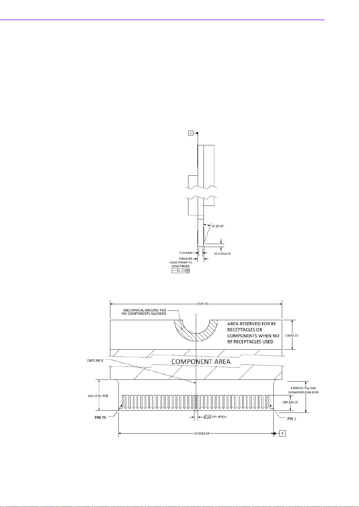
Figure 2.1 Card Edge Bevel
Figure 2.2 Card Edge Outline-Topside
WISE-1530 User Manual 6
Page 15
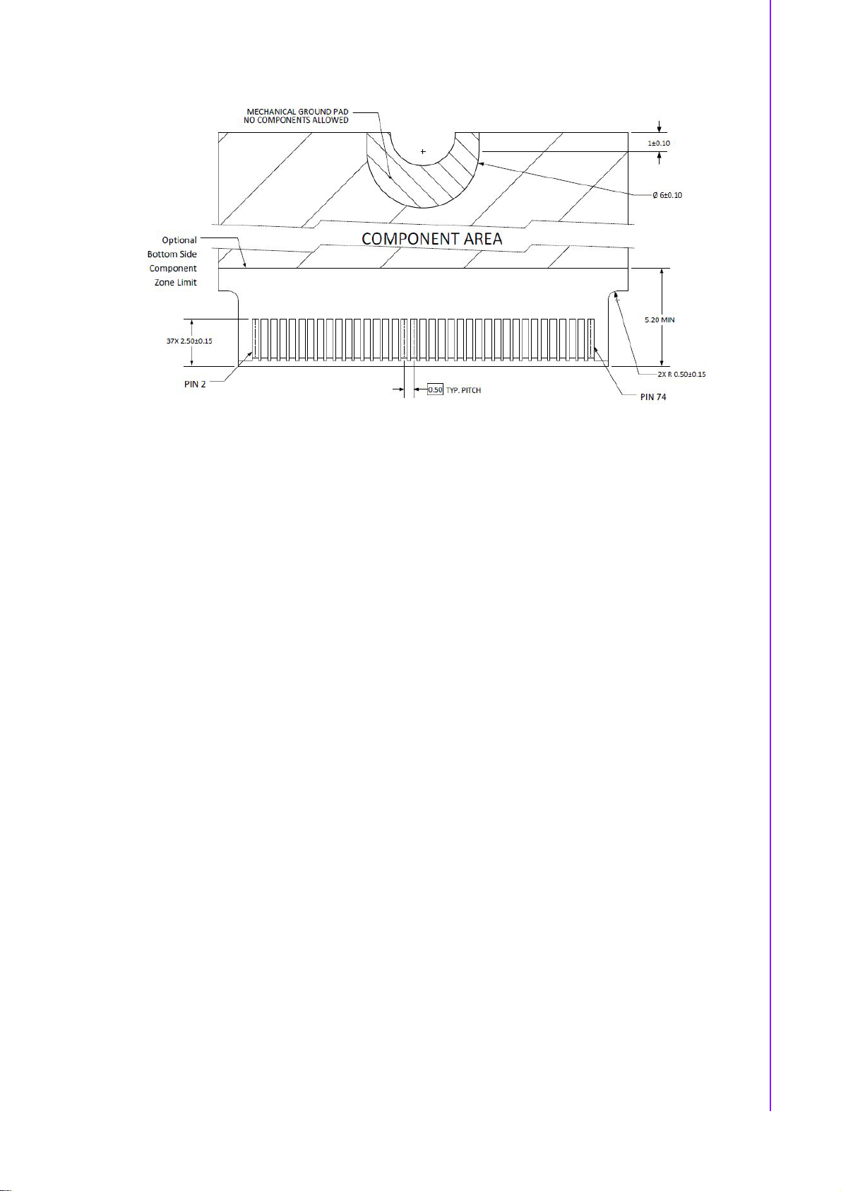
Figure 2.3 Card Edge Outline-Backside
Reference from PCI Express M.2 Specification Rev 1.0 (Nov 1, 2013) Section 2.3.5
Card PCB Details
Chapter 2 H/W Installation
7 WISE-1530 User Manual
Page 16

2.2 Module Outline
The mechanical dimension information of M2.COM form factor follows the Type A
2230 module size: 22 x 30 mm. Both module types use a 75-position host interface
connector and have room to support up to four RF connectors in the upper section.
Figure 2.4 Type A 2230
2.3 Connector Specifications
2.3.1 Top Side Connector Physical Dimensions
The top-side scheme has two connectors that share a common footp rint but h ave different stack-up requirements.
Length - 22 mm maximum including land pattern
Width - 9.1 mm maximum including land pattern
WISE-1530 User Manual 8
Page 17

Chapter 2 H/W Installation
Figure 2.5 Top Side Connector Physical Dimensions
Reference from PCI Express M.2 Specification, Revision 1.0, November 1, 2013
2.3.2 Carrier Board Connection Length
The carrier board connector of M2.COM follows the p Type 2230 M.2 module connector:
The additional increase in length is 7.05mm maximum for top-side connector to
the module length.
The retention screw adds 2.75 mm maximum.
The maximum extension, including land pattern, beyond the module leading
edge is 4.3 mm.
M2.COM module lengths are 30 mm and 42 mm.
9 WISE-1530 User Manual
Page 18

Figure 2.6 Carrier Board Connection Length
Reference from PCI Express M.2 Specification, Revision 1.0, November 1, 2013
2.3.3 Carrier Board Connector Height
The dimensions of M2.COM form factor follow the T ype A 2230 -D3 M.2 module size.
Hence, the carrier board connectors must choose H3.2-D3 or H4.2-D5 connector as
in the following diagrams.
Figure 2.7 H3.2-D3
Reference from PCI Express M.2 Specification, Revision 1.0, November 1, 2013
WISE-1530 User Manual 10
Page 19

2.4 WISE-1530 Pin-Out Map
Chapter 2 H/W Installation
M2.COM
PIN
Signal name
1 GND GND 3.3V VCC 2
3 MICRO_USB_HS_DP PA12 3.3V VCC 4
MICRO_USB_HS_D
5
N
7 GND GND PB12 I2S_CK_MICRO 8
9 NC PA4 I2S_WS_MICRO 10
11 NC PC12 I2S_SD_MICRO 12
13 NC NC 14
15 NC PB14 CB_RESET_OUT# 16
17 NC GND GND 18
19 NC PC9 CB_PWR_ON 20
21 NC PA9 UART3_TX (O)(0/3.3V) 22
23 NC Connector Key
Connector Key Connector Key
Connector Key Connector Key
Connector Key Connector Key
Connector Key PA10 UART3_RX (I)(0/3.3V) 32
33 GND GND NC 34
35 NC NC 36
37 NC PA5 GPIO_0_MICRO 38
39 GND GND PB0 GPIO_1_MICRO 40
41 NC NC 42
43 NC PB13 GPIO_3_WL 44
45 GND GND PB0 GPIO_4_WL 46
47 ADC0_MICRO PA6 PB2 GPIO_5_WL 48
49 ADC1_MICRO PA7 PB1 GPIO_6_WL 50
51 GND GND NC 52
53 ADC2_MICRO PC4 NC 54
55 ADC3_MICRO PC5 NC 56
57 GND GND PB7 I2C0_SDA 58
59 NC PB6 I2C0_SCL 60
61 NC PC3 SPI_MOSI 62
63 GND GND PC2 SPI_MISO 64
65 +VBAT_R VBAT(3.3V) PB13 SPI_SCK 66
67 NC PB9 SPI_CS0# 68
69 GND GND NC 70
71 RESET_IN# NRST 3.3V VCC 72
73 WAKEUP_MICRO# PC0 3.3V VCC 74
75 GND GND
STM32L443RCI6
MCU Pin Name
PA11 NC 6
M2.COM
Signal name
PIN
11 WISE-1530 User Manual
Page 20

Figure 2.8 M.2 Connector
2.5 Quick Starter of WISE-1530
2.5.1 Preparing for Hardware
The user needs to prepare for hardware as following:
WISE-1530, WISE-1500 and WISE-ED22.
802.11b/g/n (2.4 GHz) Wireless Access Point (AP).
PC Runs on Windows®, Mac® OS X®, and Linux®
Please refer to the following steps for setup a WISE series of boards before using
WISE-1530.
Step 01: Please prepare boards as below.
1.WISE-1530
2.WISE-1500
3.WISE-ED22
4.WISE-ED22 reset button
5.CN2 on WISE-1500
WISE-1530 User Manual 12
Page 21

Please check pin1 and pin2 to "OFF" as
default.
6.SW3 on WISE-1500
7.WISE-1530 reset button, one button
on WISE-1500 and the other on WISEED22
8.Micro USB connector
9.RF connector (connect to an
antenna)
10.Power connector
11.Antenna (connect to RF connector)
Step02: Connect the WISE-ED22 to PC using micro-USB cable.
(Please refer to http://ess-wiki.advantech.com.tw/view/WISE-
ED22_User_Manual#Connection_with_target_board)
Switch pin2 to decide whether running
"backup to default" while device booting.
"ON": enabled, "OFF": disable
Drag-n-drop programming
Serial port and debugging
Power supplies for UART1 debug port
Chapter 2 H/W Installation
1. Install Driver
2.The device will be visible in the Device Manager as below, user can use serial
tools (putty, tera term etc.) to key-in command.
13 WISE-1530 User Manual
Page 22

WISE-1530 User Manual 14
Page 23

Chapter 3
3 Development
Environment Setup
Page 24

3.1 Overview
WISE-1530 is used Cypress's WICED® SDKs to develop Wi-Fi and BLE application.
WISE-1530 SDK use C/C++ language Runs on Windows® through Eclipse®-based
integrated development environment (IDE).
Single installer package with support for:
Wi-Fi + Bluetooth combo so lution
– Wi-Fi solutions
– Bluetooth (Basic Rate, Enhanced Data Rate and Bluetooth Low Energy)
Sample applications for many popular use cases like
– Connecting to cloud services
– Low-power BLE-based sensors and beacons
– Smart home gateways
– BLE-WiFi introducer
Code snippets to understand WICED APIs
User can refer to WICED Software(http://www.cypress.com/products/wiced-software)
to get more information.
WISE-1530 User Manual 16
Page 25

3.2 Installation of WICED Studio
The user can refer to the following steps to setup WICED Studio with WISE-1530
SDK.
3.2.1 Windows Install
1. Download WICED-Studio-5.2.0.22-IDE-Installer.zip(https://commu-
nity.cypress.com/servlet/JiveServlet/downloadBody/13651-102-1-14558/
WICED-Studio-5.2.0.22-IDE-Installer.zip)
2. Extract the installer exe from the zip file to temp folder on your computer; do not
execute the installer from the zip file
3. Double click the installer exe to install WICED Studio as below picture
Chapter 3 Development Environment Setup
17 WISE-1530 User Manual
Page 26

WISE-1530 User Manual 18
Page 27

4. After installation is completed, launch WICED Studio IDE from shortcut on desk-
top
5. When you see the Select WICED Platform page, choose the 43xxx_Wi-Fi item.
You can change in "WICED Platform" in SDK toolbar as well.
Chapter 3 Development Environment Setup
3.2.2 Copy patch file
1. Download and unzip WM-BN-BM-22_SDK_5.1.x_platform_patch.zip(http://ess-
wiki.advantech.com.tw/wiki/images/c/c1/WM-BN-BM22_SDK_5.1.x_platform_patch_v1.2.zip)
2. Replace the folders under WICED directory <SDK folder>\43xxx_Wi-Fi\ with
patch folders.
19 WISE-1530 User Manual
Page 28

3.3 Build Source File
3.3.1 Make a "Make Target" file
Step1: In Make Target window click mouse right button
Step2: Select New...
Step3: Type "snip.gpio-WISE_1530"
Field explanation: snip.gpio-WISE_1530
snip.gpio: application project name
WISE_1530: platform name, for WISE-1530 platform don't change this field
WISE-1530 User Manual 20
Page 29

3.3.2 Build Project
Double click "Make Target" file to build project.
Chapter 3 Development Environment Setup
You see below message when image is built successfully.
21 WISE-1530 User Manual
Page 30

WISE-1530 User Manual 22
Page 31

3.4 Generate a Programming File
It will generate three bin files in <SDK folder>\43xxx_Wi-Fi\build folder when build
complete.
1. Bootloader: waf.bootloader-NoOS-WISE_1530.bin
2. DCT(Device Configuration Table): DCT.bin:
3. Application: snip.gpio-WISE_1530.bin
Chapter 3 Development Environment Setup
Download and install J-Link(https://www.segger.com/downloads/jlink/
JLink_Windows_V616j.exe)software, we need J-Flash tool to combine three bin files
for programming.
23 WISE-1530 User Manual
Page 32

3.4.1 Launch J-Flash
3.4.2 Open bootloader bin file
WISE-1530 User Manual 24
Page 33
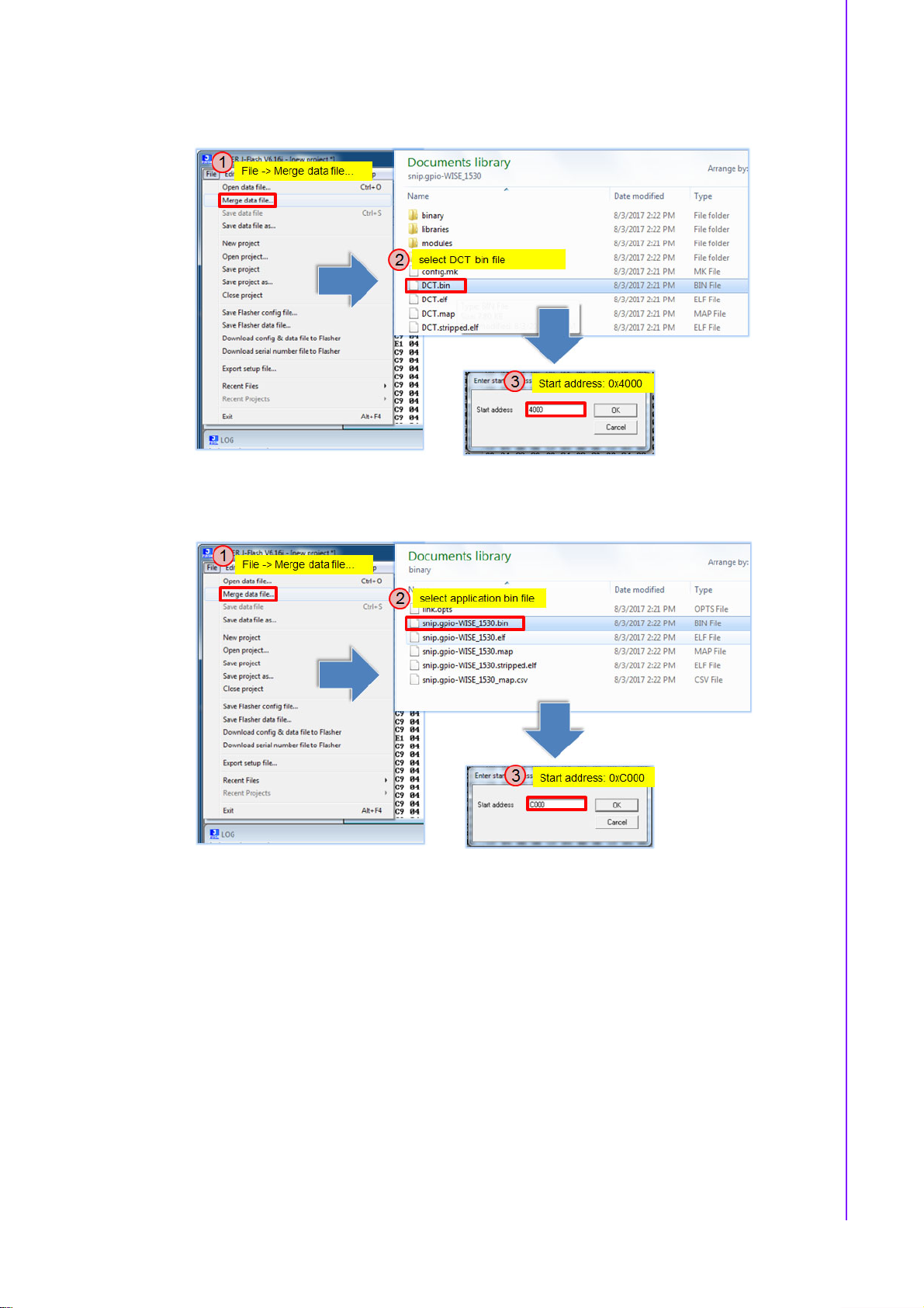
3.4.3 Merge DCT bin file
3.4.4 Merge application bin file
Chapter 3 Development Environment Setup
25 WISE-1530 User Manual
Page 34

3.4.5 Save as a final bin file
3.5 Programming
Generate a programming file then use WISE-ED22(http://ess-wiki.advantech.com.tw/
view/WISE-ED22_User_Manual)to program WISE-1530. User can refer WISE-ED22
Drag-n-drop Programming(http://ess-wiki.advantech.com.tw/view/WISEED22_User_Manual#Drag-n-drop_Programming)section
3.5.1 Debug Setting
Launch a serial port tool (Take Tera Term for example), then setting is as below.
WISE-1530 User Manual 26
Page 35

Press WISE-1530 reset button, the screen will show as below.
Chapter 3 Development Environment Setup
27 WISE-1530 User Manual
Page 36

WISE-1530 User Manual 28
Page 37

Chapter 4
4 Example: WISE-1530
Demo(StartKit)
Page 38

4.1 Introduction
There are two main functions in Demo application. One is an BLE and WiFi introducer example. It demonstrates GATT database initialization, DCT configuration, processing read/write requests from a BLE client, and sending data to the client. The
BLE WiFi Introducer has two components, an app running on a WICED devices, and
an app(BLE Scanner) running on Android device. The other main function is WISESnail exapmle. It demonstrates how to get the sensor value from WISE-DB1500
carrier board and upload data to WISE-PaaS/RMM cloud server.
4.2 Detailed about WISE-1530 Demo
The detailed behavior about Demo example is introduced as following:
System initiation.
Initiation hardware, Wi-Fi wlan connectivity, button1 thread etc.
BLE and WiFi introducer
WISE-1530 will try to connect to WiFi AP with default SSID and password at first.
If success, WISE-1530 will Loop in WISESnail. Otherwise, BLE will be used for
setting SSID and password. User can scan WISE-1530 as BLE device via
mobile app. The compile procedures please follow Chapter 4.2 Step by step
usage guide .
Initiation sensor and access data from it.
The TI HDC1050 sensor has been designed-in on WISE-DB1500 carrier board.
It's a digital humidity sensor with integrated temperature sensor. The HDC1050
is initialized in example and the user can get data of humidity and temperature.
Loop in WISESnail or web service.
When device connect to AP and get IP, it will connect to WISE-PaaS/RMM
server, keep getting sensor data and do the data exchang through WISESnail. It
is an infinite system for cloud service.
WISE-1530 User Manual 30
Page 39

4.3 Step by step usage guide
Step 1: Download and unzip WISE_1530_patch.zip(http://ess-wiki.advantech.com.tw/wiki/images/5/51/WISE_1530_patch_v06.zip), then copy WISE_1530
folder to <SDK folder>\43xxx_Wi-Fi\apps. Project Explorer window will appear
WISE_1530 folder. You can press 'F5' to refresh if you do not see.
Chapter 4 Example: WISE-1530 Demo(StartKit)
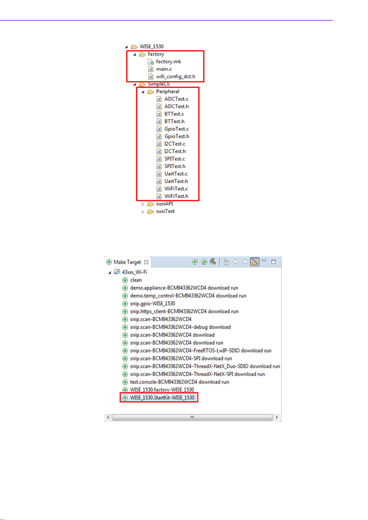
Step 2: Create a "WISE_1530.StartKit-WISE_1530" target file and build the application.
31 WISE-1530 User Manual
Page 40

Step 3: Follow "Generate a Programming File(http://ess-wiki.advantech.com.tw/view/
WISE-1530_SDK#Generate_a_Programming_File)" to generate a bin file, then
download bin file to WISE-1530. You will see below message in console screen if
success.
Step 4 to step 8 Please install BLE scanner app in your mobile phone.
Step 4: Install and launch the BLE Scanner app.
Step 5: Launch BLE Scanner and click on scan device, it will list all the BLE devices
nearby. Find the WiFiInt device and press CONNECT button.
WISE-1530 User Manual 32
Page 41

Chapter 4 Example: WISE-1530 Demo(StartKit)
Step 6: If the connection between mobile phone and WISE-1530 is successful, you
will access configuration page and select "CUSTO M SERVICE" to modify SSID and
PASSWORD of WiFi AP.
Step 7: Find the UUID: ACA0EF7C-EEAA-48AD-9508-19A6F6B356 for SSID characteristic. Press the "W" button to enter input window. Input new SSID name then
press the OK button. Last, user can press "R" button to check new SSID name.
33 WISE-1530 User Manual
Page 42
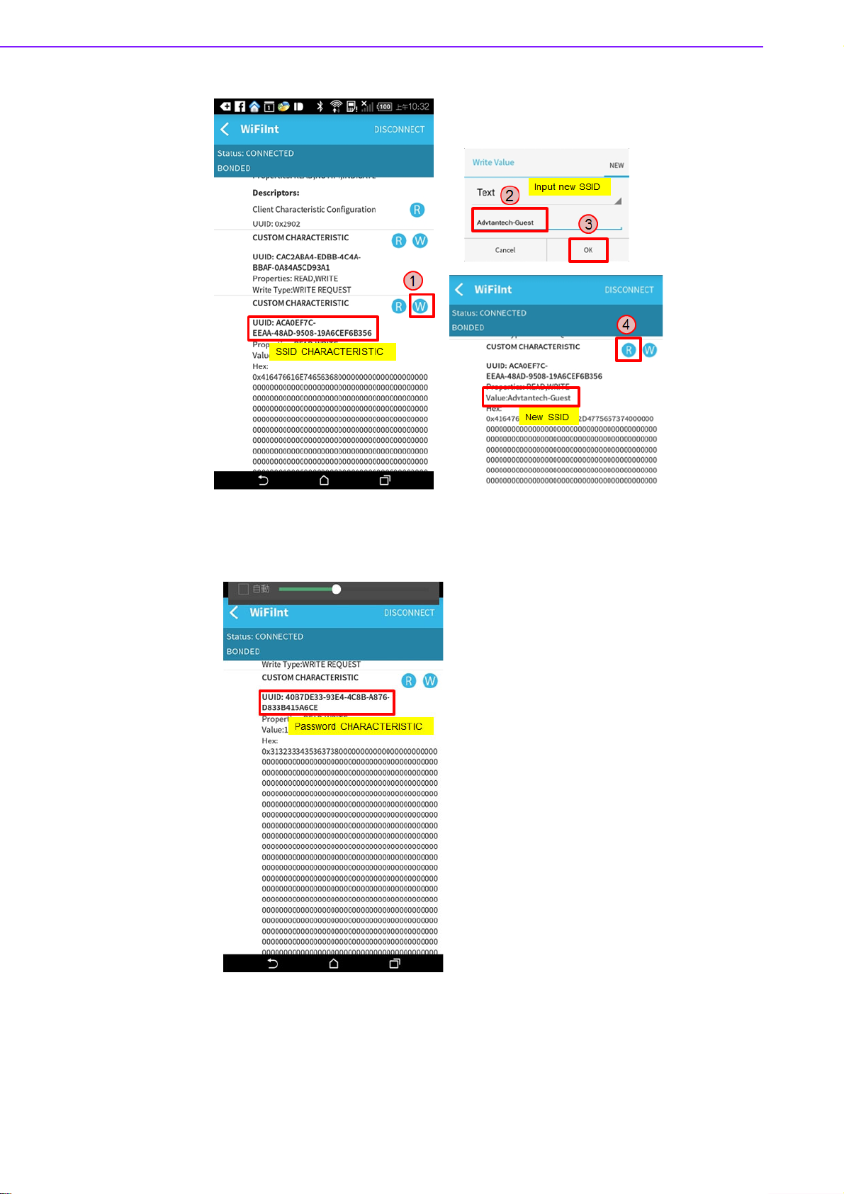
Step 8: Find the UUID: 40B7DE33-93E4-4C8B-A876-D833B415A6CE for Pass-
word characteristic then procedure as Step5.
Step 9: If it succeed to access WiFi AP, WISE-1530 will get network IP. The console
message is as below.
WISE-1530 User Manual 34
Page 43

Step 10: If it connect to broker and WISESnail successfully, user can see temperature, humidity, GPIO1 and GPIO2 on cloud server.
Chapter 4 Example: WISE-1530 Demo(StartKit)
35 WISE-1530 User Manual
Page 44

4.4 memory/flash usage
The WISE-1530 has 1 MBytes flash and 256 KBytes RAM. The Start kit flash and
memory usage is as below.
Module Flash Static RAM
Adv_WiseSnail 18284 27096
Bluetooth_Embedded_Low_Energy_Stack 154 57
bluetooth_low_energy 78493 9348
button_manager 588 4
command_console 3688 404
command_console_wifi 11146 0
crc 1060 0
DHCP_Server 1524 132
DNS 1724 44
GPIO_button 120 4
Host MCU-family library 15718 2492
Interrupt Vectors 388 0
libc 48018 3364
MQTT_Client 5643 736
Networking 5113 13280
NetX-Duo - Interfaces & Stacks 0 16
Other 170044 2930
Packet Buffers 0 23088
platform 1620 308
RAM Initialisation 4028 0
resources 385936 0
Ring_Buffer 112 0
Star tup Stack & Link Script fill 144 25
Supplicant - BESL 3470 812
WISE-1530 User Manual 36
Page 45

ThreadX 8596 400
TLV 28 0
WICED 5452 1040
WICED_Bluetooth_Firmware_Driver 36692 0
wiced_log 290 1104
wifi_utils 1082 36
WWD 20429 3176
TOTAL (bytes) 825556 89896
4.5 I/O Test (factory)
4.5.1 Introduction
The I/O Test application is a WISE-1530 I/O testing example. It's need extra I/O
board(WISE-ED30) to plug in to WISE-1500. The hardware setup as below. This
instance could test m2.com I/O that WISE-1530 supported(M2.COM Pinout(http://
ess-wiki.advantech.com.tw/view/MCU/WISE-1530)), include GPIO, ADC, I2C.
SPI...etc interface. It used WICED SDK API to read and write I/O.
Chapter 4 Example: WISE-1530 Demo(StartKit)
4.5.2 I/O Test Use WICED API
Step 1: Download and unzip WISE_1530_patch.zip(http://ess-wiki.advantech.com.tw/wiki/images/5/51/WISE_1530_patch_v06.zip), then copy WISE_1530
folder to <SDK folder>\43xxx_Wi-Fi\apps.
Step 2: I/O test source code please refer as below files.
37 WISE-1530 User Manual
Page 46
Step 3: Create a "WISE_1530.factory-WISE_1530" target file and build the application. Download firmware to WISE-1530 then press reset button.
Step 4: You will see below message in console screen if success. Input '1' to select I/
O Function Test, the screen will show I/O test items.Input 1~7 to test I/0 and 0 to
return previous page.
WISE-1530 User Manual 38
Page 47

4.5.3 I/O Test Use SUSI API
Chapter 4 Example: WISE-1530 Demo(StartKit)
The I/O Test example also support SUSI API (please refer SUSI_API(http://esswiki.advantech.com.tw/wiki/images/5/51/WISE_1530_patch_v06.zip)).The SUSI
support GPIO, I2C, SPI, ADC and PWM APIs. You can simple revise setting to
accomplish SUSI API I/O Test.
Step 1: The SUSI API I/O test source code are as below files.
Step 2: Open SimpleCli.mk and change USE_SUSI_API to 1.
39 WISE-1530 User Manual
Page 48

Step 3: Double click "WISE_1530.factory-WISE_1530" target file and build the application. Then download the firmware to WISE-1530, you can see the screen that
same as I/O Function Test.
WISE-1530 User Manual 40
Page 49

Chapter 4 Example: WISE-1530 Demo(StartKit)
41 WISE-1530 User Manual
Page 50

www.advantech.com
Please verify specifications before quoting. This guide is intended for reference
purposes only.
All product specifications are subject to change without notice.
No part of this publication may be reproduced in any form or by any means,
electronic, photocopying, recording or otherwise, without prior written permission of the publisher.
All brand and product names are trademarks or registered trademarks of their
respective companies.
© Advantech Co., Ltd. 2019
 Loading...