

Advantech UTX-3117FSP-S6A2N, UTX-3117FS-S6A1N, UTX-3117FS-S6A2N, UTX-3117C-S6A2N, UTX-3117C-S6A2E User Manual
...Page 1

The information contained in this document has been carefully researched and is, to the best of our
knowledge, accurate. However, we assume no liability for any product failures or damages, immediate or
consequential, resulting from the use of the information provided herein. Our products are not intended for
use in systems in which failures of product could result in personal injury. All trademarks mentioned herein
are property of their respective owners. All specifications are subject to change without notice.
Manual
ADVANTECH
UTX-3117
Embedded BOX PC with Intel® Apollo Lake Prozessor
Page 2
User Manual
UTX-3117
Page 3

Copyright
The documentation and the software included with this product are copyrighted 2018
by Advantech Co., Ltd. All rights are reserved. Advantech Co., Ltd. reserves the right
to make improvements in the products described in this manual at any time without
notice. No part of this manual may be reproduced, copied, translated or transmitted
in any form or by any means without the prior written permission of Advantech Co.,
Ltd. Information provided in this manual is intended to be accurate and reliable. How ever, Advantech Co., Ltd. assu mes no responsibility for its use, nor for any infringements of the rights of third parties, which may result from its use.
Acknowledgements
Intel® and Pentium® are trademarks of Intel Corporation.
Microsoft® Windows® and MS-DOS® are registered trademarks of Microsoft Corp.
All other product names or trademarks are properties of their respective owners.
Product Warranty (2 years)
Advantech warrants to you, the original purchaser, that each of its products will be
free from defects in materials and workmanship for t wo year s from the date of purchase .
This warranty does not apply to any products which have been repaired or altered by
persons other tha n repair pe rson nel authorized by Adva ntech , or whi ch have bee n
subject to mi sus e, abuse , accident or improper installation. Ad vant ech ass umes no
liability under the terms of this warranty as a consequence of such events.
Because of Advantech’s high quality-control standards and rigorous testing, most of
our customers never need to use our repair service. If an Advantech product is defective, it will be repaired or replaced at no charge during the warranty period. For outofwarranty repairs, you will be billed according to the cost of replacement materials,
service time and freight. Please consult your dealer for more details.
If you think you have a defective product, follow these steps:
1. Collect all the information about the problem encountered. (For example, CPU
speed, Advant ech products us ed, other hardware and software used, etc.) Note
anyt hing abnormal and list any onscr een messages you get wh en the probl em
occurs.
2. Call your dealer and describe the problem. Please ha ve your manual, product,
and any helpful information readily available.
3. If your product is diagnosed as defective, obtain an RMA (return merchandise
authorization) number from your dealer. This allows us to process your return
more quickly.
4. Carefully pack the defective product, a fully-completed Repair and Replacement
Order Card and a photocopy proof of purchase date (such as your sales receipt)
in a shippable container. A product returned without proof of the purchase date
is not eligible for warranty service.
5. Write the RMA number visibly on the outside of the package and ship it prepaid
to your dealer.
Part No. Edition 1
Printed in Taiwan March 2018
UTX-3117 User Manual ii
Page 4
Declaration of Conformity
FCC Class B
Note: This equipment has been tested and found to comply with the limits for a Class
B digital device, pur suant to part 15 of the F C C Rules. These limits are desi gned to
provide reas ona ble protectio n aga inst harmful interference in a residential installation. T his equip ment generates, uses and can radiate radio frequenc y energy and, if
not installed and used in accordance with the instructions, ma y cause harmful interference to radio communicati ons . Ho w ever, there is no guarantee that interference
will not occur in a particular installation. If this equipment does cause harmful interference to radio or television reception, which can be determined by turning the equipme nt off and on, the user is encour a ged to try to correct t he interference by one or
more of the following measures:
Reori ent or relocate th e receiving antenna.
Increase the s eparatio n between the equi pment and recei ver.
Connect the equipment into an outlet on a circuit different from that to which the
receiver is connected .
Consult the dealer or an experienced radio/TV technician for help.
Warning! Any changes or modifications made to the equipment which are not
expressly approved by the relevant standards authority could void your
authority to operate the equipment.
Caution! Danger of explosion if battery is incorrectly replaced. Replace only with
the same or equivalent type recommended by the manufacturer. Dispose of used batteries according to the manufacturer’s instructions.
This device co mplies with Part 15 of the FCC Rules. Operation is subject to the following two conditions : (1) Thi s device may not cause harmful interference, and (2)
this devi ce must acc ept any interference received, includi ng int erference t hat may
cause undesired operation.
iii UTX-3117 User Manual
Page 5

Technical Support and Assistance
1. Visit the Advantech website at http://support.advantech.com where you can find
the latest information about the product.
2. Contact your distributor, sales representative, or Advantech's customer service
center for technical sup port if you need additional assistance. Please have the
following information ready before you call:
– Product name an d serial number
– Description of your peripheral attachments
– Description of your software (operating system, version, application software,
etc.)
– A complete description of the problem
– T he exact wordin g of any error messages
Warning!
1. Input voltage rated 12~24 VDC, 3 ~ 5 A (DC Mode).\
2. Packing: please carry the unit with both hands, handle with care.
3. Maintenance: to properly maintain and clean the surfaces, use only
approved products or clean with a dry applicator.
Safety Instructions
1. Read these safety instructions carefully.
2. Keep this User Manual for later reference.
3. Disconnect this equipment from any AC outlet before cleaning. Use a damp
cloth. Do not use liquid or spray detergents for cleaning.
4. For plug-in equipment, the power outlet socket must be located near the equip-
ment and must be e asily accessible .
5. Keep this equipment away from humidity.
6. Put this equipment on a reliable surface during installation. Dropping it or letting
it fall may ca use damage.
7. Th e openings on the enclosure are for air convection. Protect the e quipment
from overheating. DO NOT COVER THE OPENINGS.
8. Make sure the voltage of the power source is correct before connecting the
equipment to the p ower outlet.
9. Position the po wer cord so that people cannot step on it. Do not place anything
over the power cord.
10. All cautions and warnings on the equipment should be noted.
11. If the equipment is not used for a long time, disconnect it from the power source
to avoid damage by transient overvoltage.
12. Never pour any liquid into an opening. This may cause fire or electrical shock.
13. Never open the eq uipment . For safety reasons, the equi pment should be
opened only by qualified service personnel.
14. If one of the following situations arises, get the equipment checked by service
perso nnel:
a. The power cord or plug is d amage d.
b. Liquid ha s penetrated into the equipment.
c. The equipment h as been expos ed to moisture.
d. The equipment does not work well, or you cannot get it to work according to
the user's man ual.
e. The equipme nt h as b een dro pped and da mage d .
UTX-3117 User Manual iv
Page 6
f. The equipment has obvious signs of breakage.
15. DO NOT LEAVE THIS EQUIPMENT IN AN ENVIRONMENT WHERE THE
STORAGE TEMPERATURE MAY GO BELOW -20° C (-4° F) OR ABOVE 60° C
(140° F). THIS COULD DAMAGE THE EQUIPMENT. THE EQUIPMENT
SHOULD BE IN A CONTROLLED ENVIRONMENT.
16. If your computer is losing dramatic time or the BIOS configuration reset to
default, the battery has no power.
Caution!
1. Do not replace power adaptor yourself. Please contact a qualified
technician or your retail.
2. The computer is provided with a battery-powered real-time clock
circuit. There is a danger of explosion if battery is incorrectly
replaced. Replace only with same or equivalent type recommended by the manufacture. Discard used batteries according to
the manufacturer’s instructions.
17. CLASSIFICATION:
– Supply by Class I
adapter – No applied part
– Continuous Operation
– Not AP or AP G category
18. Follow the national requirement to dispose unit.
19. Maintenance: to properly maintain a nd clean the surfaces, use only the
approved products or clean with a dry cloth.
20. Contact information:
No.1, Alley 20, Lane 26, Rueiguang Road Neihu District, Taipei, Taiwan 114,
R.O.C
TEL: (02)27927818
Industry Canada Statement
This device complies with RSS-210 of the Industry Canada Rules. Operation is subject to the following two conditions: (1) This device ma y not cause harmful interferenc e, and (2 ) this devi ce must acce pt any inte r feren ce rec eive d, inc l uding
interference that may cause undesired operati on.
French User Manual Statements for RSS Warnings
FCC/Industry Canada Two-Part Statement:
English Version
This devi ce complies wi th F C C Part 15 and Indus try Can a d a license exe mpt R S S
standard(s). Operation is subject to the following two conditions: (1) this device may
not cause i nterference, and (2) this devi ce must accept a n y i nterference , incl udi ng
interference that ma y cause unde sired operation of the device.
Version française
Ce t appareil e st c onforme à F C C P artie1 5 d’Industrie Cana da RS S standard
exempts de licence (s). Son utilisation es t sou mise à Les deux conditions suivantes:
(1) cet appareil ne peut pas provoquer d’interférences et (2) cet appareil doit
accepter Toute interférence, y compris les interférences qui peuvent causer un mauvais fonctionnement du dispositif.
v UTX-3117 User Manual
Page 7

Version française
"Les cha ngements ou modifications non expressé ment approuvés par la partie
responsable de la conformité pourraient annuler l'autorité de l'utilisateur à utiliser cet
équipement."
European Union Declaration of Conformity Statement
We, Advantech , declare under our sole responsibility that th e product, model, is in
conformity with all applicable essential requirements Necessary for CE marking, following the provisions of the European Council Directives 2004/108/EC (EMC Directive), 2006/95/EC (Low Voltage Directive), 1999/5/EC (Radio and
Telecommunications Terminal Equipment Directive) and 2011/65/EU (ROHS Directive).
The product is properly CE marked demonstrating this conformity and is for distribution within all member states of the EU with no restrictions.
This product follows the provisions of the European Directives 2004/108/EC, 2006/
95/EC, 1999/5/EC and 2011/65/EU.
Čeština Tento výrobe k odpovídá požadavkům e vropských směrnic 2004/108/E C,
2006/95/EC, 1999/5/EC a 2011/65/EU.
Dansk Dette produkt er i overensstemmelse med det europæiske direktiv 2004/108/
EC, 1999/5/EC, 2006/95/EC & 2011/65/EU.
Du tch Dit product is in navolging va n de bepalingen van Eur opees Directief 2004/
108/EC, 1999/5/EC, 2006/95/EC & 2011/65/EU.
Eesti Antud toode vastab Euroopa direktiivides 2004/108/EC, ja 2006/95/EC ja 1999/
5/EC ja 2011/65/EU kehtestatud nõuetele.
Suomi Tämä tuote noudattaa EU-direktiivin 2004/108/EC, 1999/5/EC, 2006/95/EC &
2011/65/EU määräyksiä.
Français Ce produit est c onforme aux exigences de la Directive Européenne 2004/
108/EC, 1999/5/EC, 2006/95/EC & 2011/65/EU.
Deutsch Dieses Produkt entspricht den Bestimmungen der Europäischen Richtlinie
2004/108/EC, 1999/5/EC 2006/95/EC & 2011/65/EU.
Εηνά Τ παό πό αυί τ ατά τ Ευπαώ Ογώ 2004/
108/EC, 1999/5/EC, 2006/95/EC α 2011/65/EU.
Magyar E termék megfelel a 2004/108/EC, 1999/5/EC, 2006/95/EC és 2011/65/EU
Európai Irányelv előírásainak.
Icelandic Þessi vara stenst re glugerð Evrópska Efnahags Bandalagsins núme r
2004/108/EC, 2006/95/EC, & 2011/65/EU.
UTX-3117 User Manual vi
Page 8

Italiano Questo prodotto è conforme alla Direttiva Europea 200 4/108/EC, 199 9/5/
EC, 2006/95/EC & 2011/65/EU.
Latviešu Šis produkts atbilst Eiropas Direktīvu 2004/108/EC, 1999/5/EC, 2 006/95/
EC un 2011/65/EU noteikumiem.
Lietuvi ų Šis produktas atitinka Europos direktyvų 2004/108/EC, 1999/5/EC, 2006/
95/EC, ir 2011/65/EU nuostatas.
Malti Dan il-prodott hu konformi mal-provvedimenti tad-Direttivi Ewropej 2004/108/
EC, 1999/5/EC, 2006/95/EC u 2011/65/EU.
Norsk Det te produkte t er i hen hold til best emme lsene i det eu rope iske direktivet
2004/108/EC, 1999/5/EC, 2006/95/EC & 2011/65/EU.
Polski Niniejszy produkt jest zgodny z postanowieniami Dyrektyw Unii Europejskiej
2004/108/EC, 1999/5/EC, 2006/95/EC i 2011/65/EU.
Po rtug uese Este pr oduto cumpre com as normas da Diretiva Européia 2004/108/
EC, 1999/5/EC, 2006/95/EC & 2011/65/EU.
Español Este producto c umple con las normas del Directivo Europeo 2004/108/EC,
1999/5/EC, 2006/95/EC & 2011/65/EU.
Slovensky Tento produkt je v súlade s ustanoveniami európskych direktív 2004/108/
EC, 1999/5/EC, 2006/95/EC a 2011/65/EU.
Slovenščina Izdelek je skladen z določbami evropskih direktiv 2004/108/EC, 1999/
5/EC, 2006/95/EC in 2011/65/EU.
Sve n ska D enna produkt har tillverkats i enlighet med EG-direktiv 2004/108/ EC,
1999/5/EC 2006/95/EC & 2011/65/EU.
Türkçe Bu ürün, Avrupa Birliği’nin 2004/108/EC, 1999/5/EC, 2006/95/EC ve 2011/
65/EU yönergelerine uyar.
This symbol on the product indicates co mpliance with Directive 2002/96/EC
(WEEE). Do not dispose of product in unsorted municiple waste.
Please recycle t his p rod uct in a responsible ma n ner. Refer to local envir onmental
regulati ons fo r pr oper rec ycli ng; do not disp ose of p roduct in u nsor ted municipa l
wa ste.
vii UTX-3117 User Manual
Page 9

Packing List
Before installation, please ensure the following items ha ve been shipped:
1 x UTX-3117 unit
1 x DC 12 V 36 W power adaptor
1 x China R o HS
1 x Warranty card
1 x C hine se user man u al
Ordering Information
P/N CPU SSD Mem ory WiFi 3G/LTE Other RF An ten na OS
UTX-3117FS-S6A1N
PENTIUM N4200, 4C 2M
1.1 GHz
32GB 4 GB X 1 NA NA NA
4
NA
UTX-3117FS-S6A2N
CELERON N3350 2C 2M
1.1 GHz
32GB 4 GB X 1 NA NA NA
4
NA
UTX-3117 FS-S6A2E
Atom X5-E3940 4C 2M
1.6 GHz
32GB 4 GB X 1 NA NA NA
4
NA
UTX-3117FSWS6A1N
PENTIUM N4200, 4C 2M
1.1 GHz
32GB 4 GB X 1 NA NA NA
4
WIN 10
UTX-3117 FSP-S6A2N
CELERON N3350 2C 2M
1.1 GHz
32GB 4 GB X 1 NA NA NA
4
Pulsa r 8
UTX-3117C-S6A2N
CELERON N3350 2C 2M
1.1 GHz
NA NA
NA NA NA
NA NA
UTX-3117C-S6A2E
Atom X5-E3940 4C 2M
1.6 GHz
NA NA
NA NA NA
NA NA
UTX-3117C-S6A1N
PENTIUM N4200, 4C 2M
1.1 GHz
NA NA
NA NA NA
NA NA
UTX-3117SA4-S6A1N
PENTIUM N4200, 4C 2M
1.1 GHz
NA 4GB X 1 NA NA NA
4
NA
UTX-3117SA4-S6A2N
CELERON N3350 2C 2M
1.1 GHz
NA 4GB X 1 NA NA NA
4
NA
UTX-3117 SA4-S6A2E
Atom X5-E3940 4C 2M
1.6 GHz
NA 4GB X 1 NA NA NA
4
NA
UTX-3117 User Manual viii
Page 10
Compatibility List
Power Cord
Part Number Description
17 000 01524
Power Cable 3-pin 180cm, U SA type
(For power adapter 1757004096-01)
17 02031 83C
Po wer Cable 3-pin 180 cm, Europe type
(For power adapter 1757004096-01)
170203 180A
Power Cable 3-pin 180cm, UK type
(For po wer adapter 1757004096-01)
17 000 08921
Power Cable 3-pin 18 3cm, P SE Mark type
(For power adapter 1757004096-01)
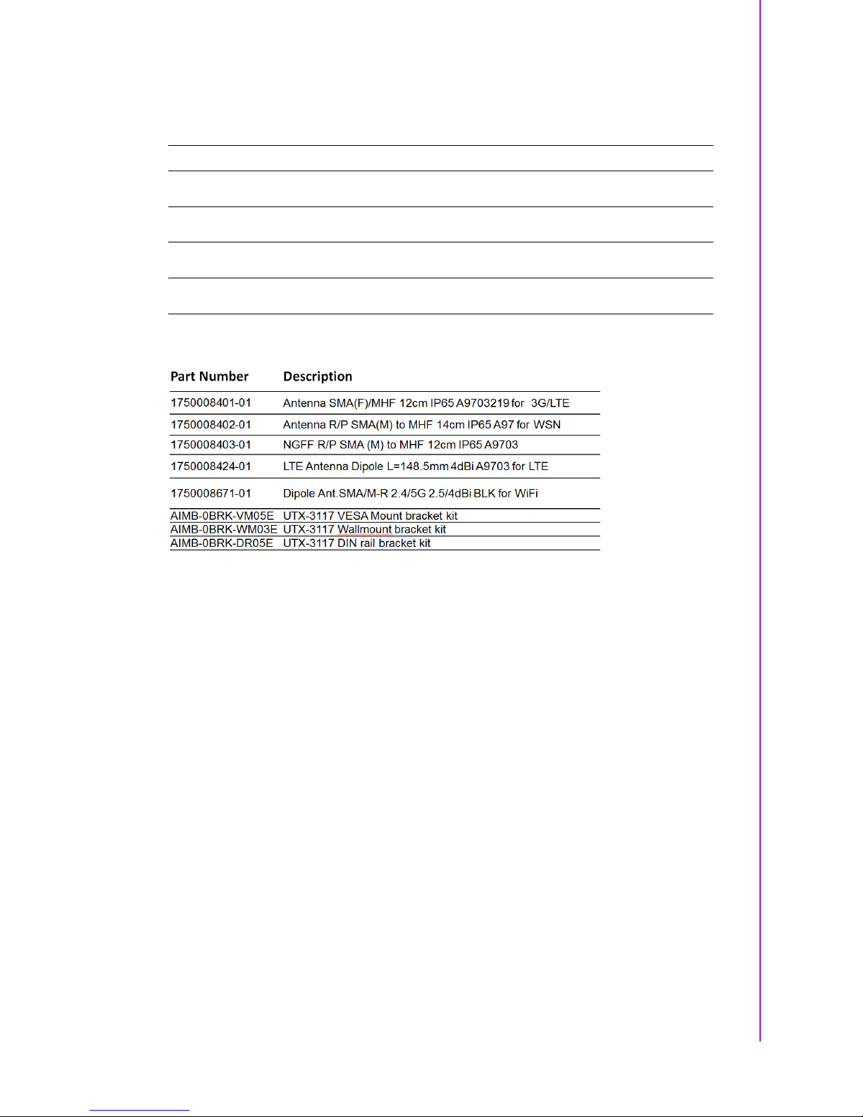
Optional Items
ix UTX-3117 User Manual
Page 11

UTX-3117 User Manual x
Page 12

Contents
Chapter 1 Introduction..........................................1
1.1 Overview...................................................................................................2
1.2 Syste m Configuration........................................ ........................................3
1.3 Gener al Specifications..............................................................................4
1.3.1 Standard PC Functions.................................................................4
1.3.2 Po we r Environmental................................. ...................................4
1.4 Mecha nical Specifications.........................................................................4
1.4.1 Mechanical Specifications (Terminal)...........................................4
1.5 Environmental Specifications....................................................................5
Chapter 2 Jumper and Connector List ................7
2.1 Conne ctors & Jumpers..............................................................................8
Figure 2.1 T op View.....................................................................8
Figure 2.2 Bot tom Vie w ...............................................................9
Table 2 .1 : RS485/R S422selection pin he ader (J485/422)........10
Table 2.2: AT/ATX Mode Selection (PSON1)............................10
2.2 Connectors............................................................... ...............................10
2.2.1 CP U-S ys tem on chip (SOC1 ) ......................................................10
2.2.2 B IOS Flash(SPI1) .......................................................................11
2.2.3 DDR3L SO-DIMM Socket (DIMMA1)..........................................11
2.2.4 DC i nput Connector(DCIN1).......................................................11
2.2.5 MINIP CIE Connector (MINI-PCIE1)............................................12
2.2.6 S IM Card Socket (SIM1).............................................................13
2.2.7 Lo w Pin Count Header (LPC1) ...................................................13
2.2.8 MINIPCIE and mSATA Connector (MINI-PCIE2) .......................14
2.2.9 SPI Programming Pin H ead er (SPI_CN1)..................................15
2.2.10 COM Port (COM1)......................................................................16
2.2.11 Ge neral P ur pose I/ O Pin Header (GPIO1)..................................16
2.2.12 HD Analog Audio Interface (AUDIO1).........................................17
2.2.13 COM Port (COM2)......................................................................17
2.2.14 N ext Generatio n Form Factor (M.2_1)........................................18
2.2.15 S ATA Signal Connec tor (SATA1)...............................................19
2.2.16 USB 3.0 Connector(USB1).........................................................19
2.2.17 USB 3.0 Connector(USB2).........................................................19
2.2.18 SAT A P ower Connector (SATA_PWR1).....................................20
2.2.19 R J45 Connector(LAN1)...................... .........................................20
2.2.20 R J45 Connector(LAN1)...............................................................20
2.2.21 High Definition Multimedia Interface(HDMI1)..............................21
2.2.22 Di sp layPort (DP1).......................................................................21
2.2.23 DDR3 L SO-DIMM Socket (DIMMB1)..........................................22
2.2.24 S ATA LED(D10)..........................................................................22
2.2.25 P ower Bu tto n(PWRBTN 1) ..........................................................22
Chapter 3 Peripheral Installation .......................23
3.1 HDD Installation......................................................................................24
3.2 Mini P CIe Module Installation..................................................................26
Chapter 4 BIOS Setup .........................................29
4.1 Introd uction .............................................................................................30
4.2 Entering Set up ........................................................................................31
xi UTX-3117 User Manual
Page 13

4.2.1 Mai n Menu.................................................................................. 31
4.2.2 Advanc ed BIO S Features........................................................... 32
4.2.3 Chipset........................................................................................ 52
4.2.4 Security Boo t .............................................................................. 59
4.2.5 B oot ............................................................................................ 61
4.2.6 Save & Exit................................................................................. 62
UTX-3117 User Manual xii
Page 14

Chapter 1
1
This Chapter briefly introduces
the UTX-3117 product.
Introduction
Page 15

1.1
Overview
Th e Advantech U TX-3 117 system is fanless & ext ended=temp embedded box. The
solution uses the latest Intel® Atom® E3900, Celeron® N3350, and Pentium®
N4200 series processor technology to provide a real-time IoT computing, power-efficient, plug & play gateway which is ideal for smart city street lighting, smart metering,
smart parking, smart agriculture, HVAC, healthcare, industrial automation and more.
UTX-3117 is compatible with Microsoft Windows 10 IoT Enterprise, Yocto Linux, and
Wind Ri ver Pulsar OS. Furthermore, UTX-3117 has Advantech intelligent software
WISE -PaaS integrated and is certificated with AWS Greengrass IoT solution to offer
a total solution for bridging connectivity from edge sensors to the cloud.
Benefits:
Ultra Thin ITX embedded system with CE/FCC certification
Fanless, wide-temperature operation with high performance and flexibility
Design in 3 extension slot for RF module, mSATA, or other I/O dongle.
Support 12V ~ 24V wide voltage DC input.
One-Stop Integrated Solution: Integrated ultra compac t motherboard, chas-
sis,peripherals a nd software
Di mensions: 152 x 128 x 37.1 mm
UTX-3117 User Manual 2
Page 16
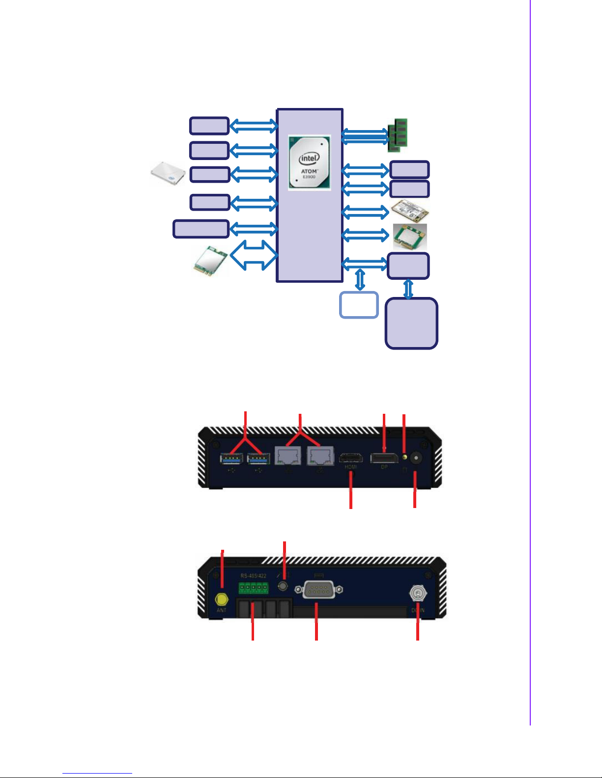
1.2
System Configuration
The following diagram is a block drawing of the UTX-3117.
HDMI
DP1.2
1 SATA 3.0
DDI
DDI
600M Bs
PC IE x1
DD R3L Non -ECC
1333 /1600/ 1867
MHz, up to 8G
GbE 1:
I211AT
2 USB3.0
ALC892,
Line out /MIC in
US B3.0
HD AUDIO
Intel
Apollo Lake
N4200/E39xx SoC
TDP:5.5~13W
PC IE x1
US B2.0
PC IE x1
US B2.0
SATA 3.0
GbE 2:
RTL8111G
F/S mini PCI E,
w/SI M ho ld
(3G/LTE module)
H/S mini PCIE,
Colay mS ATA
M.2 E key
(WIFI / GPS/ BT
/Zig bee mo dule)
PC IE x1
USB2 .0
Pow er: DCI N12~24 V
LP C Bus
TPM
Infin eon
SLB 9660
Sup er I/O
NCT5523D
1 RS-232
1 RS-4 22/ 485
8bit GPIO
WDT
H/W moitor
Button I/O arrangement:
USB 3.0
LAN
HDMI
DP HDD LED
Power Bu on
WSN ANT Audio Jack
RS-422/485 RS-232 12-24V DC IN
3 UTX-3117 User Manual
Chapter
1
Introduction
Page 17
1.3
General Specifications
1.3.1
Standard PC Functions
CPU: Intel® Atom™ E3900 series, Pentium N4200, Celeron N3350 SoC.
BIOS: AMI EFI 16bit
Memory: DDR3L SODIMM 1333/1866 MHz up to 8GB
Audio: HD audio codec ALC892
LAN: PCI-E gIGABIT Ethernet controllers x2
LAN1: Intel i210AT; LAN2: RTL8111G
Universal serial bus (USB) port: 2 USB3.0
Mini PCI-E bus expansion slot: 1 F/S miniPCIE support 3G/LTE card; 1 H/S
miniPCIE support mSATA/WIFI card, 1 M.2 E-key support WiFI card.
Storage housing: 1 2.5" slim SSD
Audio output: Combo Audio Jack
Video output: 1 HDMI, 1 Display port
1.3.2
Power Environmental
Power adaptor: AC/DC
– Input voltage: 100 Vac ~ 240 Vac @ 50 - 60 Hz,1.5
A
– Output voltage: 12 V @ 3 A~24V @ 3A
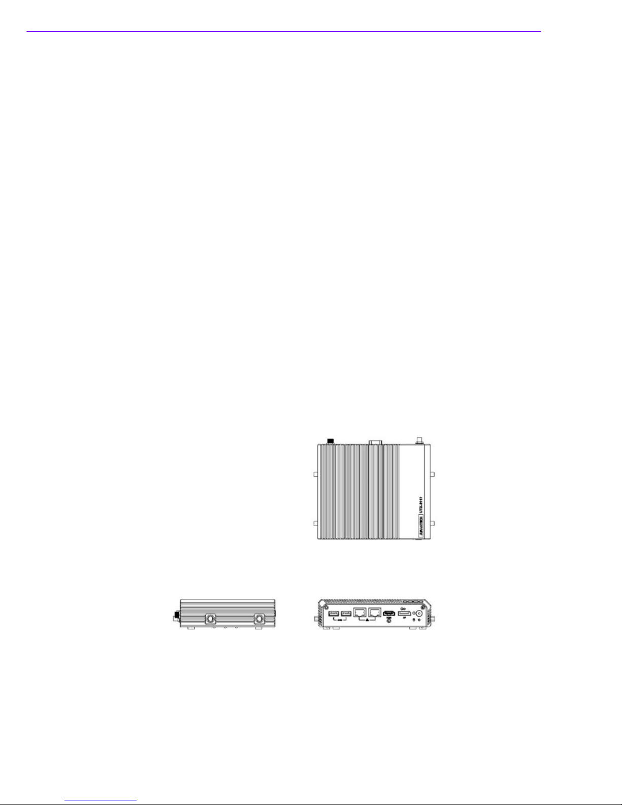
1.4 Mechanical Specifications
1.4.1
Mechanical Specifications (Terminal)
System Dimensions: 152 X 128 X 37.1 mm (5.98" X 5.2" X 1.46")
Carton Dimensions: 255 (L) X 235 (W) X 160 (H) mm
Gross Weight: 2.0 kg
Net Weight: 1.8 kg
UTX-3117 User Manual 4
Page 18

1.5
Environmental Specifications
Temperature & Humidity
Operating Temperature: -20 ~ 60 ° C (with RF module)
Storage Temperature: -40 ~ 60° C
Relative Humidity: 40 ~ 95% RH (Non-condensed)
Safety
CE / UL/CB/CCC/BSMI
EMI
FCC class B approved for USA, Canada, and E U
Vibration:
With SSD: 3Grms, 60068-2-64, random, 5 ~ 500 Hz, 1 hr/axis
5 UTX-3117 User Manual
Chapter
1
Introduction
Page 19

UTX-3117 User Manual 6
Page 20

Chapter 2
2
Connector List
Jumper and
Page 21
2.1
Connectors & Jumpers
Figure 2.1 Top View
UTX-3117 User Manual 8
Page 22
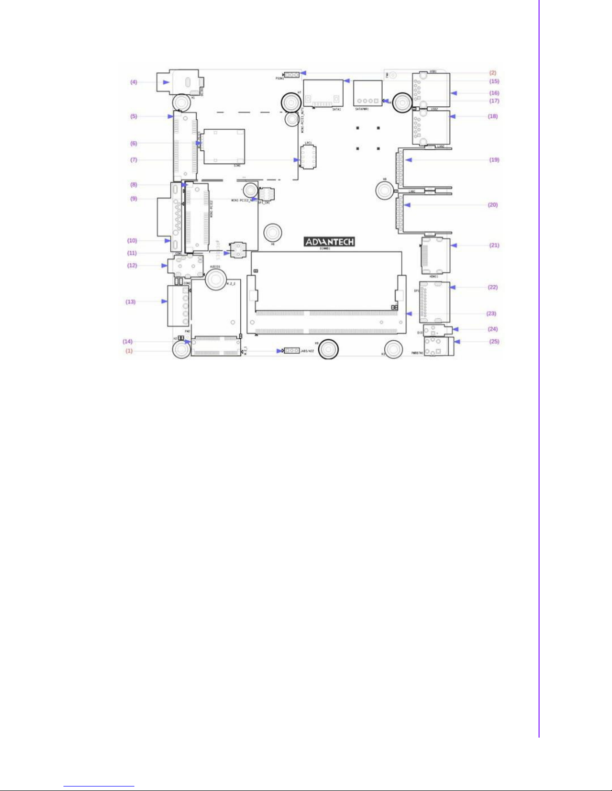
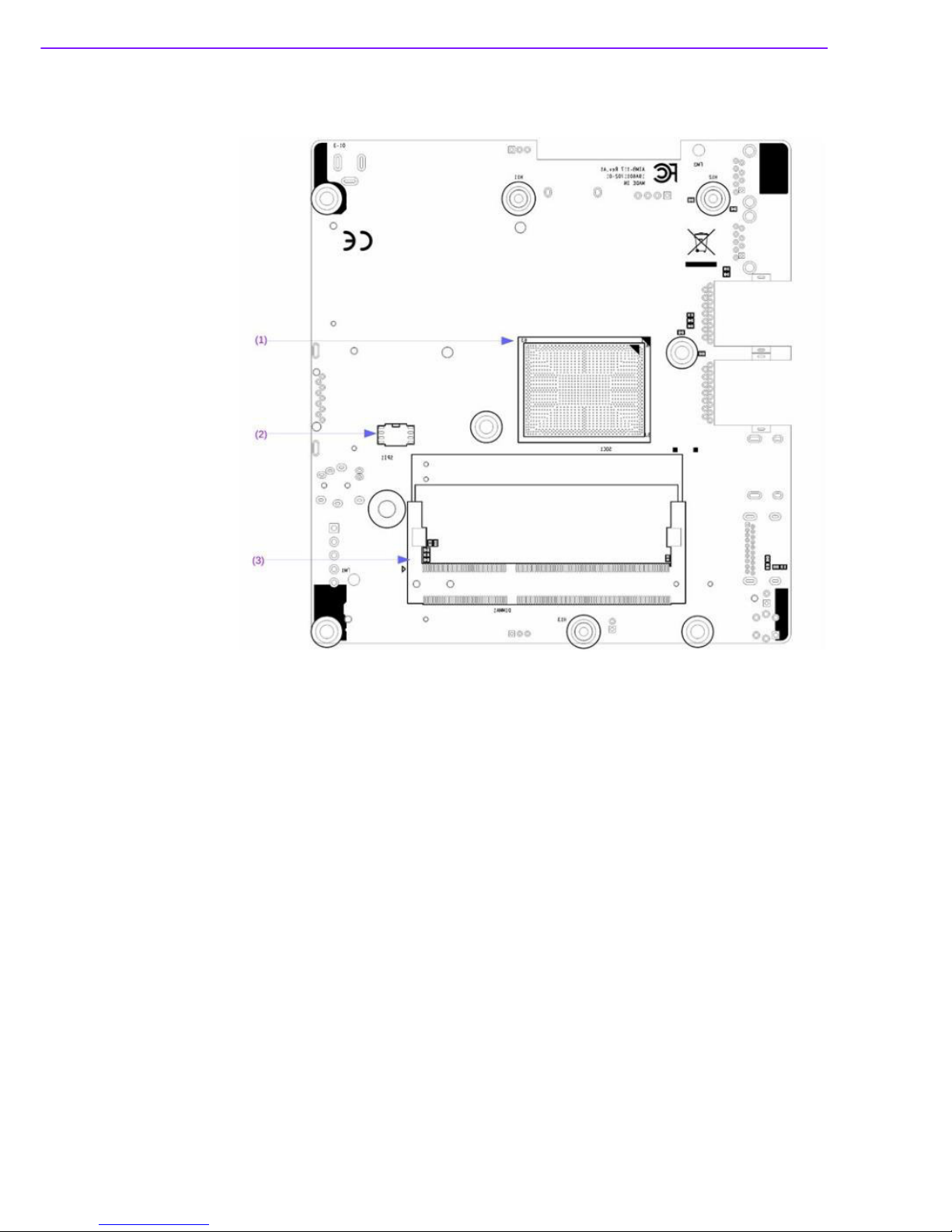
Figure 2.2 Bottom View
Connector and Header List:
(1) CPU-System on chip(SOC1)
(2) BIOS Flash(SPI1)
(3) DDR3LSO-DIMM Socket (DIMMA1)
(4) DC input Connector (DCIN1)
(5) MINIPCIE Connector (MINI-PCIE1)
(6) SIM Card Socket (SIM1)
(7) Low Pin Count Header (LPC1)
(8) MINIPCIE and mSATA Connector (MINI-PCIE2)
(9) SPI Programming Pin Header(SPI_CN1)
(10) COM Port(COM1)
(11) General Purpose I/O Pin Header (GPIO1)
(12) HDAnalog Audio Interface(AUDIO1)
(13) COM Port(COM2)
(14) Next Generation Form Factor (M.2_1)
(15) SATA Signal Connector (SATA1)
(16) USB 3.0 Connector(USB1)
(17) SATA Power Connector (SATA_PWR1)
(18) USB 3.0 Connector(USB2)
(19) RJ45 Connector(LAN2)
(20) RJ45 Connector(LAN1)
(21) High Definition Multimedia Interface(HDMI1)
(22) DisplayPort(DP1)
(23) DDR3LSO-DIMM Socket (DIMMB1)
9 UTX-3117 User Manual
Chapter
2
Jumper
and
Connector
List
Page 23
(24) SATA LED(D10)
(25) Power Button(PWRBTN1)
Jumper List:
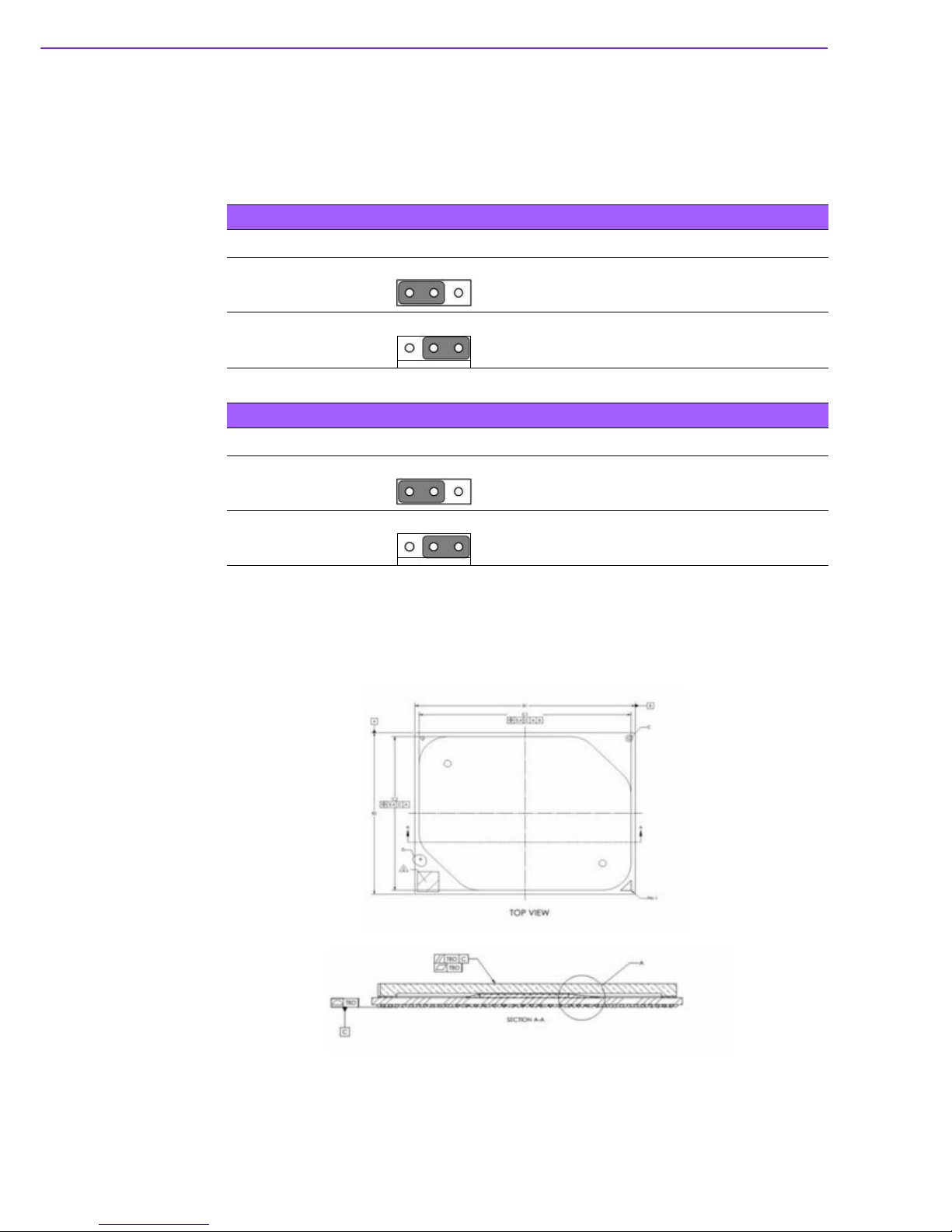
(1) RS485/RS 422selection pin header (J485/422)
Table 2.1: RS485/RS422selection pin header (J485/422)
Function Setting
RS485 (Default)
1 2 3
1 2 3
1 and 2
RS 2 32
2 and 3
Table 2.2: AT/ATX Mode Selection (PSON1)
Function Setting
AT Mode
1 2 3
1 2 3
1 and 2
ATX Mode (Default)
2 and 3
2.2
Connectors
2.2.1
CPU-System on chip(SOC1)
UTX-3117 User Manual 10
Page 24
2.2.2
BIOS Flash(SPI1)
Pin Signal Pin Signal
1 SPI _Z_ CS0 6 SPI_Z_CLK
2 SPI_Z_MISO 7 SPI_Z_IO3
3 SPI_Z_IO2 8 +V1.8SB_SPI
4 GND
5 SPI_Z_MOSI
2.2.3
DDR3L SO-DIMM Socket (DIMMA1)
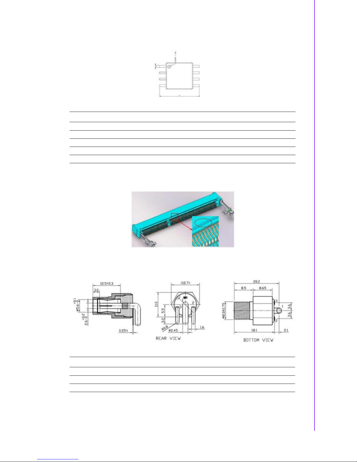
2.2.4
DC input Connector(DCIN1)
Pin Signal
1 Power input
2 GND
3 GND
11 UTX-3117 User Manual
Chapter
2
Jumper
and
Connector
List
Page 25

2.2.5
MINIPCIE Connector (MINI-PCIE1)
MINIPCIE:
Pin Signal Pin Signal
1 WAKE# 2 +3.3Vaux
3 Rese r ved 4 GND
5 Rese r ved 6 +1.5V
7 Rese r ved 8 SIM_VCC1
9 GND 10 SIM_IO1
11 Res erved 12 SIM_CLK1
13 Re served 14 SIM_RST1
15 GND 16 SIM_SPU1
17 Re served 18 GND
19 Re s erved 20 DISABLE#
21 GND 22 RE SET#
23 Re served 24 +3.3Vaux
25 Re served 26 GND
27 GND 28 +1.5V
29 GND 30 Reserved
31 Re served 32 Res erved
33 MINI-PCIE1 _RESET# 34 GND
35 GND 36 USB_D37 GND 38 USB_D+
39 +3.3Vaux 40 GND
41 +3.3Vaux 42 Reserved
43 Re served 44 Res erved
45 Re served 46 Res erved
47 Re served 48 +1.5V
49 Re served 50 GND
51 Re served 52 +3.3Vaux
UTX-3117 User Manual 12
Page 26

2.2.6
SIM Card Socket (SIM1)
Pin Signal Pin Signal
C1 SIM_VCC1 H1 GND
C2 SIM_RST1 H2 GND
C3 SIM_CLK1 H3 GND
C5 GND H4 GND
C6 SIM_SPU1
2.2.7
Low Pin Count Header (LPC1)
Pin Signal Pin Signal
1 SOC_LPC_AD1 2 CLKOUT_25M_LPC
3 SOC_LPC_AD0 4 PM_PLTRST#
5 +V3.3 6 SOC_LPC_FRAME#
7 GND 8 SOC_LPC_AD3
9 X 10 SOC_LPC_AD2
13 UTX-3117 User Manual
Chapter
2
Jumper
and
Connector
List
Page 27

2.2.8
MINIPCIE and mSATA Connector (MINI-PCIE2)
MINIPCIE:
Pin Signal Pin Signal
1 WAKE# 2 +3.3Vaux
3 Re s erv ed 4 GND
5 Re s erv ed 6 +1.5V
7 CLKREQ# 8 Re ser ved
9 GND 10 Re ser ved
11 REFCLK- 12 R eserved
13 REFCLK+ 14 R ese rved
15 GND 16 Reserve d
17 Rese rve d 18 GND
19 Reser ved 20 DISABLE#
21 DETECT# 22 R ESET #
23 PCIE_RX+ 24 +3.3Vaux
25 PCIE_RX- 26 GND
27 GND 28 +1.5V
29 GND 30 SMB_CLK
31 PCIE_TX- 32 SMB_DATA
33 PCIE_TX+ 34 GND
35 GND 36 USB_D37 GND 38 USB_D+
39 +3.3Vaux 40 GND
41 +3.3Vaux 42 Reserve d
43 V1.2_DETECT# 44 LED_WLAN#
45 Rese rve d 46 Reserved
47 Rese rve d 48 +1.5V
49 Rese rve d 50 GND
51 MSATA_DETECT# 52 +3.3Vaux
mSATA:
Pin Signal Pin Signal
1 Res erve d 2 +3.3V
3 Res erve d 4 GND
5 Res erve d 6 +1.5V
7 Res erve d 8 Re ser ved
9 GND 10 R eserved
UTX-3117 User Manual 14
Page 28

11 R eser ved 12 Res erv ed
13 Re served 14 Res erved
15 GND 16 Rese rve d
17 Re served 18 GND
19 Re served 20 Res erved
21 DETECT# 22 Reserved
23 RX+ 24 +3.3V
25 RX- 26 GND
27 GND 28 +1.5V
29 GND 30 SMB_CLK
31 TX- 32 SMB_DATA
33 TX+ 34 GND
35 GND 36 Rese rve d
37 GND 38 Rese rve d
39 +3.3V 40 GND
41 +3.3V 42 Reserved
43 Re served 44 Res erved
45 Re served 46 Res erved
47 Re served 48 +1.5V
49 Re served 50 GND
51 MSATA_DETECT# 52 +3.3V
2.2.9
SPI Programming Pin Header (SPI_CN1)
Pin Signal Pin Signal
1 CS# 2 +3.3V
3 MISO 4 X
5 X 6 SCK
7 GND 8 MOSI
15 UTX-3117 User Manual
Chapter
2
Jumper
and
Connector
List
Page 29

2.2.10
COM Port (COM1)
Pin Signal Pin Signal
1 DCD# 6 DSR#
2 RXD 7 RTS#
3 TXD 8 CTS#
4 DTR# 9 RI#
5 GND
2.2.11
General Purpose I/O Pin Header (GPIO1)
Pin Signal Pin Signal
1 GPIO0 2 GPIO4
3 GPIO1 4 GPIO5
5 GPIO2 6 GPIO6
7 GPIO3 8 GPIO7
9 +3.3V 10 GND
UTX-3117 User Manual 16
Page 30

2.2.12
HD Analog Audio Interface (AUDIO1)
Pin Signal Pin Signal
1 CONN_FRONT_L 6 GND_A
2 CONN_FRONT_R MS1 GND_A
3 GND_A MS2 GND_A
4 CONN_MIC1_L H1 x
5 FRONT_SENSE_A H2 x
2.2.13
COM Port (COM2)
Pin Signal
1 COM2_422_485_TX2 COM2_422_485_TX+
3 GND
4 COM2_422_RX5 COM2_422_RX+
17 UTX-3117 User Manual
Chapter
2
Jumper
and
Connector
List
Page 31

2.2.14
Next Generation Form Factor (M.2_1)
Pin Signal Pin Signal
1 GND 43 PCIE_RX32 +V3.3SB_M.2 44 x
3 USB_D4+ 45 GND
4 +V3.3SB_M.2 46 x
5 USB_D4- 47 CK100M_NGFF+
6 x 48 x
7 GND 49 CK100M_NGFF8 NGFF_I2S3_Z_BCLK 50 NGFF_PMU_SUSCLK
9 SDIO_WIFI_CLK 51 GND
10 NGFF_I2S3_Z_SYNC 52 NGFF_PLTRST#
11 SDIO_WIFI_CMD 53 PCIE_REQ2_ NG FF#
12 NGFF_I2S3_Z_SDI 54 NGFF_BT_DISABLE#
13 SDIO_WIFI_D0 55 PCIE_NGFF_WAKE2#
14 NGFF_I2S3_Z_S DO 56 NGFF_WIFI_DISABLE#
15 SDIO_WIFI_D1 57 GND
16 x 58 x
17 SDIO_WIFI_D2 59 x
18 GND 60 x
19 SDIO_WIFI_D3 61 x
20 NGFF_CONN_UART_WAKE# 62 x
21 SDIO_WIFI_WAKE# 63 GND
22 NGFF_UART0_Z_RXD 64 x
23 SDIO_WIFI_RST 65 x
32 NGFF_UART0_Z_TXD 66 x
33 GND 67 x
34 NGFF_UART0_Z_CTS# 68 x
35 NGFF_PCIE_TX3+ 69 GND
36 NGFF_UART0_Z_RTS# 70 x
37 NGFF_PCIE_TX3- 71 x
38 x 72 +V3.3SB_M.2
39 GND 73 x
40 x 74 +V3.3SB_M.2
41 PCIE_RX3+ 75 GND
42 x
UTX-3117 User Manual 18
Page 32

2.2.15
SATA Signal Connector (SATA1)
Pin Signal Pin Signal
1 GND 6 SATA0_Z_RX+
2 SATA0_Z_TX+ 7 GND
3 SATA0_Z_TX- 8 x
4 GND 9 x
5 SATA0_Z_RX- 6 SATA0_Z_RX+
2.2.16
USB 3.0 Connector(USB1)
2.2.17
USB 3.0 Connector(USB2)
Pin Signal Pin Signal
1 +USBV1 7 GND
2 USB_D0- 8 USB3X0_Z_TX3 USB_D0+ 9 USB3X0_Z_TX+
4 GND H1 GND_F1
5 USB3X0_Z_RX- H2 GND_F1
6 USB3X0_Z_RX+ x
19 UTX-3117 User Manual
Chapter
2
Jumper
and
Connector
List
Page 33

2.2.18
SATA Power Connector (SATA_PWR1)
Pin Signal Pin Signal
1 +V5 3 GND
2 GND 4 x
2.2.19
RJ45 Connector(LAN1)
2.2.20
RJ45 Connector(LAN1)
RJ45
Pin Signal Pin Signal
R1 LAN2_TCT R10 LAN2_MDI3R2 LAN2_MDI0+ R11 LAN1_TCT
R3 LAN2_MDI0- H1 GND_LAN
R4 LAN2_MDI1+ H2 GND_F1
R5 LAN2_MDI1- L1 LAN2_LED1_Z_ACT#
R6 LAN2_TCTG L2 +V3.3_LAN2
R7 LAN2_MDI2+ L3 LAN2_LED2_Z_1G#
R8 LAN2_MDI2- L4 LAN2_LED0_Z_100M#
UTX-3117 User Manual 20
Page 34

2.2.21
High Definition Multimedia Interface(HDMI1)
Pin Signal Pin Signal
1 HDMI1_Z_D2+ 11 GND
2 GND 12 HDMI1_Z_CLK3 HDMI1_Z_D2- 13 x
4 HDMI1_Z_D1+ 14 x
5 GND 15 HDMI1_SCL
6 HDMI1_Z_D1- 16 HDMI1_SDA
7 HDMI1_Z_D0+ 17 GND
8 GND 18 +V5_HDMI
9 HDMI1_Z_D0- 19 HDMI1_HPD
10 HDMI1_Z_CLK+
2.2.22
DisplayPort (DP1)
Pin Signal Pin Signal
1 DP1_0+ 11 GND
2 GND 12 DP1_33 DP1_0- 13 DP1_AUX_EN#
4 DP1_1+ 14 GND
5 GND 15 DP1_AUX+
6 DP1_1- 16 GND
7 DP1_2+ 17 DP1_AUX8 GND 18 DP1_ DP_HPD
9 DP1_2- 19 GND
10 DP1_3+ 20 +V3.3_DP1
21 UTX-3117 User Manual
Chapter
2
Jumper
and
Connector
List
Page 35

2.2.23
DDR3L SO-DIMM Socket (DIMMB1)
2.2.24
SATA LED(D10)
2.2.25
Power Button(PWRBTN1)
UTX-3117 User Manual 22
Page 36

Chapter 3
3
Peripheral Installation
Page 37

3.1
HDD Installation
1. Unscrew the botto m cover screws.
2. Secure 2.5" SATA HDD onto the bottom cover. The screws are in the accessory
box.
UTX-3117 User Manual 24
Page 38

3. Connect SATA signal and power cable to the 2.5" SATA HDD.
4. Secure the bottom cover in its original position.
25 UTX-3117 User Manual
Chapter
3
Peripheral
Installation
Page 39

3.2
Mini PCIe Module Installation
1. Unscrew the botto m cover screws.
2. Insert Mini PCIe module into the slot and secure the screw to fix the module.
UTX-3117 User Manual 26
Page 40

3. Connect the antenna cable to module.
4. Secure the bottom cover in its original position.
27 UTX-3117 User Manual
Chapter
3
Peripheral
Installation
Page 41

UTX-3117 User Manual 28
Page 42

Chapter 4
4
BIOS Setup
Page 43

4.1
Introduction
AM I BIOS has been integrated into many, many motherboards for decades. With the
AM I B IOS Setup program, users can modify B IOS settings and control various system features. T his chapter des crib es the basic navigatio n of the UTX-3117 B I O S
set up s creen s.
AMI's B IOS ROM has a built-in Setup program that allows users to modify the basic
system configuration. This information is stored in flash R O M so it retains the Setup
information when the power is turned off.
Note! Default BIOS is supported for 64-bit OS installation, if you have any
BIOS setting requirement, please contact with sales representative for
details.
Control Keys
< >< >< >< > Move select item
<Enter> Select item
<E sc>
Main Menu - Quit without saving changes to the CM OS
Sub Menu - Exit current page and return to the Main Me nu
<Page Up /+> I nc rease the n umeric value or make c hange s
<Page Down/ -> Decrease t he nume ric value or ma ke ch anges
<F1> Gener al help, for Setup Sub Me nu
<F2> Item help
<F5> Loa d previous values
<F7> Loa d setup defaults
<F10> Save all CMO S chan ge s
UTX-3117 User Manual 30
Page 44

4.2
Entering Setup
4.2.1
Main Menu
Press <Del> to enter AMI BIOS CMOS Setup Utility, the Main M enu will appear on
the screen. Use arrow keys to select amo ng the items and press <Enter> to accept or
enter the s ub-menu.
The Main BIOS setup scr een ha s t w o ma i n frames. The left fr a me displays all the
options that can be configured. Grayed-out options cannot be configured; options in
blue can. The right frame displays the key legend.
Above t h e key l e gend is an a rea r eserve d for a t ext message. W hen an o ption is
selected in the left frame, it is highlighted in white. Often a text message will accompany it.
System time / System date
Use this option to ch ange the sys tem t ime and date. Highlight System T ime or
System Date using the <Arrow> keys. Enter new values through the keyboard.
Pr ess the <Tab> key or the < Ar r o w > keys to move bet ween fie lds. T h e da te
must be entered in MM/DD/YY format. The time must be entered in HH:MM:SS
format.
31 UTX-3117 User Manual
Chapter
4
BIOS
Setup
Page 45

4.2.2
Advanced BIOS Features
Se lect the Ad v a nced t ab fr o m th e UT X -3117 set u p s creen to e nter th e A d vanced
BIO S S etu p scre en. Yo u can select any of the items in the left frame of the screen,
such as CPU Configuration, to go to the s ub me nu for that item. You can display an
Advanced BIOS Setup option by highlighting it using the <Arrow> keys. All Advanced
BIOS Setup options are described in this section. T he Advanced BIOS Setup screen
is shown below. The s ub menus are described on the following pages.
UTX-3117 User Manual 32
Page 46

4.2.2.1
Realtek PCIe GBE Family Controller Status
Check the status of Realtek LAN port.
4.2.2.2
Check Intel® I201 Gigabit Network connection Status
33 UTX-3117 User Manual
Chapter
4
BIOS
Setup
Page 47

4.2.2.3
Trusted Computing
UTX-3117 User Manual 34
Page 48

Security Device Support
Enable or disable BIOS support for security device.
4.2.2.4
APCI Settings
35 UTX-3117 User Manual
Chapter
4
BIOS
Setup
Page 49

Enable ACPI Auto Configuration
Enable or disable BIOS ACPI auto configuration.
Enable Hibernation
This item allows users to enable or disable hibernation.
ACPI Sleep State
This item allows users to set the A CPI sleep state.
Lock Legacy Resource
This item allows users to lock legacy device resources.
UTX-3117 User Manual 36
Page 50

4.2.2.5
NCT5523D Super IO Configuration
37 UTX-3117 User Manual
Chapter
4
BIOS
Setup
Page 51

Serial Port 1&2 Configuration
This item allows users to enable or disable serial Ports 1/2
Change Settings
This item allows users to change the serial port 1/2
4.2.2.6
Hardware Monitor
UTX-3117 User Manual 38
Page 52

This item allows you to monitor HW status
Execute Disable Bit
This item allows users to enable or disable the No-Execution page protection.
Intel Virtualization Technology
When enabled, a V MM can utilize the additional hardware capabilities provided
by Vanderpool Technology.
39 UTX-3117 User Manual
Chapter
4
BIOS
Setup
Page 53

Digital I/O Configuration
This item will allow users to set up Digital I/O 1~8 to "input" or "output".
UTX-3117 User Manual 40
Page 54

Wake System From S5
Enable or disable system wake on alar m event.
41 UTX-3117 User Manual
Chapter
4
BIOS
Setup
Page 55

Console Redirection
This item allows users to enable or disable console redirection.
4.2.2.7
CPU Configuration
This page shows CPU Information.
Active Power Cores
UTX-3117 User Manual 42
Page 56

Nu mber of cores to enable in each processor p ackage
Intel Virtualization Technology
When enabled, a V MM can utilize the additional hardware capabilities provided
by Vanderpool Technology.
VT-d
Enable or disable VT-d
Bi-directional PROCHOT
When a processor therm al sensor tr ips (eit her c ore), the P ROCHOT# w ill be
driven. If bi-direction is enabled, external agents can drive PROCHOT# to throttle the processor.
Thermal Monitor
Enable or disable Thermal Monitor
Monitor Mwait
Enable/disable Monitor Mwait.
P-STATE Coordination
Change P-STATE Coordination type.
43 UTX-3117 User Manual
Chapter
4
BIOS
Setup
Page 57

EIST
Enabled or disabled Intel Spee d Step function.
Turbo Mode
Enabled or disabled Turbo Mode
Boot performance mode
Select the performance state that the BIOS will set before OS handoff.
UTX-3117 User Manual 44
Page 58

C-States
Enabled or disabled C-States
Enhanced C-States
Enabled or disabled C1E. Wh e n enabled, C P U will switch to m i nimum speed
when all cores enter C-State.
Max Package C State
Controls the max package C state that the processor will support.
Max Core C State
This option controls the Max Core C State that cores will support.
C-State Auto Demotion
Configure C-State Auto Demotion.
C-State Un-Demotion
Configure C-State Un-demotion.
Power Limit 1 Enable
Enable/Disable Power Limit 1.
Power Limit 1 Clamp Mode
Enable/Disable Power Limit 1 Clamp Mode.
Power Limit 1 Power
Power Limit 1 in Watts. Auto will program Power Limit 1 based on silicon default
support value.
Power Limit 1 Time Window
Power Limit 1 Time Window Value in seconds. Auto will program Power Limit 1
Time Window based on silicon default support value.
45 UTX-3117 User Manual
Chapter
4
BIOS
Setup
Page 59

Network Stack
Enable or disable UEFI Network Stack.
UTX-3117 User Manual 46
Page 60

CSM Support
Enable or disable C SM Support..
4.2.2.8
NVMe Configuration
47 UTX-3117 User Manual
Chapter
4
BIOS
Setup
Page 61

4.2.2.9
USB Configuration
UTX-3117 User Manual 48
Page 62

Legacy USB Support
Enables support for legacy USB. Auto option disables legacy support if no USB
devices are connected. DISABL E option will keep US B devices available only
for EFI applications.
XHCI Hand-Off
This is a workaround for OS without XHC I hand-off support. The XHCI ownership change should claim by XHCI driver.
USB Mass Storage Driver Support
This item allows you to enable or disable the USB mass storage device support.
USB transmit time-out
US B mass storage device transmit c ommand time-out.
Device reset time-out
US B mas s storage device start unit c ommand time-out.
Device power-up delay
Max i mum time the device will take before it properly r eports itself to the host
controller. “Auto” uses default value: for a Root port it is 100ms, for a Hub port
the delay is taken from Hub descriptor.
Mass storage device
Mass storage device emulation type. 'AUT O' enume rat es devic es according to
their media for mat. Optic al drives are emulat ed as 'CDRO M ', dr ives with no
media will be emulated according to a drive type.
49 UTX-3117 User Manual
Chapter
4
BIOS
Setup
Page 63

4.2.2.10
Platform Trust Technology
fTPM
Enabled or disabled fTPM.
UTX-3117 User Manual 50
Page 64

4.2.2.11
Security Configuration
TXE HMRFPO
This item allows users to enable or disable TXE HMRFPO.
TXE EOP Message
Se nd E OP M essa ge before Enter OS.
51 UTX-3117 User Manual
Chapter
4
BIOS
Setup
Page 65

4.2.3
Chipset
4.2.3.1
North Bridge
UTX-3117 User Manual 52
Page 66

53 UTX-3117 User Manual
Chapter
4
BIOS
Setup
Page 67

OS Selection
Select the target OS.
4.2.3.2
Uncore Configuration
UTX-3117 User Manual 54
Page 68

55 UTX-3117 User Manual
Chapter
4
BIOS
Setup
Page 69

Chipset SATA
Enables or disables the chipset S A T A controller. T he chipset S A T A controller
supports the 2 black internal SATA ports (up to 3Gb/s supported per port).
SATA Mode Selection
This item allows users to select mode of SATA controller(s).
Aggressive LPM Support
This item allows users to enable or disable Aggressive LPM Support.
Port 1
This item allows users to enable or disable the Serial -ATA Port 1 device.
Spin Up Device
This item allows users to enable or disable the Spin Up Device.
SATA Device Type
Identify the SATA port is connected to Solid State Drive or Hard Disk Drive.
Port 2
This item allows users to enable or disable the Serial-ATA Port 2 device
Spin Up Device
This item allows users to enable or disable the Spin Up Device.
SATA Device Type
Identify the SATA port is connected to Solid State Drive or Hard Disk Drive.
UTX-3117 User Manual 56
Page 70

57 UTX-3117 User Manual
Chapter
4
BIOS
Setup
Page 71

UTX-3117 User Manual 58
Page 72

4.2.4
Security Boot
59 UTX-3117 User Manual
Chapter
4
BIOS
Setup
Page 73

4.2.4.1
Security Boot
Attempt Secure Boot
Secure Boot activated when platform ke y(PK) is enrolled, system mo de is user/
deployed, and CSM function is disabled.
Secure Boot Mode
UTX-3117 User Manual 60
Page 74

Secure Boot mode - Custom & Standard, Set UEFI Secure Boot Mode to STANDARD mode or CUSTO M mode, this change is effect after save. And after eset,
the mode will return to STANDARD mode.
4.2.5
Boot
Bootup NumLock State
Select the keyboard NumL ock state.
Quiet Boot
Enables or disables Quiet Boot option.
61 UTX-3117 User Manual
Chapter
4
BIOS
Setup
Page 75

4.2.6
Save & Exit
UTX-3117 User Manual 62
Page 76

63 UTX-3117 User Manual
Chapter
4
BIOS
Setup
Page 77

www.advantech.com
Please verify specifications before quoting. This guide is intended for reference
purposes only.
All product specifications are subject to change without notice.
No part of this publication may be reproduced in any form or by any means,
electronic, photocopying, recording or otherwise, without prior written permis-
sion of the publisher.
All brand and product names are trademarks or registered trademarks of their
respective companies.
© Advantech Co., Ltd. 2018
Page 78

Our company network supports you worldwide with offices in Germany, Austria, Switzerland, Great Britain and
the USA. For more information please contact:
Headquarters
Germany
FORTEC Elektronik AG
Lechwiesenstr. 9
86899 Landsberg am Lech
Phone: +49 8191 91172-0
E-Mail:
sales@fortecag.de
Internet: www.fortecag.de
Fortec Group Members
Austria
FORTEC Elektronik AG
Office Vienna
Nuschinggasse 12
1230 Wien
Phone: +43 1 8673492-0
E-Mail:
office@fortec.at
Internet: www.fortec.at
Germany
Distec GmbH
Augsburger Str. 2b
82110 Germering
Phone: +49 89 894363-0
E-Mail:
info@distec.de
Internet: www.distec.de
Switzerland
ALTRAC AG
Bahnhofstraße 3
5436 Würenlos
Phone: +41 44 7446111
E-Mail:
info@altrac.ch
Internet: www.altrac.ch
United Kingdom
Display Technology Ltd.
5 The Oaks Business Village
Revenge Road, Lordswood
Chatham, Kent, ME5 8LF
Phone: +44 1634 672755
E-Mail:
info@displaytechnology.co.uk
Internet: www. displaytechnology.co.uk
USA
Apollo Display Technologies, Corp.
87 Raynor Avenue,
Unit 1Ronkonkoma,
NY 11779
Phone: +1 631 5804360
E-Mail:
info@apollodisplays.com
Internet: www.apollodisplays.com
 Loading...