

Advantech UNO3272GJ0211903-T, UNO3272GJ0211901-T, UNO-3272G-J021AE, UNO3272GJ0211902-T, UNO3272GJ0211904-T User Manual
...Page 1
User Manual
UNO-3272G 電腦
Intel® Celeron J1900 processors
Embedded Automation
Computer, with PCIe/PCI
Extension slots
Page 2

Copyright
PN: 2003272G00 Edition 1
Printed in Taiwan May 2019
The documentation and the software included with this product are copyrighted 2019
by Advantech Co., Ltd. All rights are reserved. Advantech Co., Ltd. reserves the right
to make improvements in the products described in this manual at any time without
notice. No part of this manual may be reproduced, copied, translated or transmitted
in any form or by any means without the prior written permission of Advantech Co.,
Ltd. Information provided in this manual is intended to be accurate and reliable. However, Advantech Co., Ltd. assumes no responsibility for its use, nor for any infringements of the rights of third parties, which may result from its use.
Acknowledgements
Intel® is trademarks of Intel Corporation.
Microsoft Windows and MS-DOS are registered trademarks of Microsoft Corp.
C&T is a trademark of Chips and Technologies, Inc.
All other product names or trademarks are properties of their respective owners.
Support
For more information on this and other Advantech products, please visit our websites
at: http://www.advantech.com
For technical support and service, please visit our support website at:
http://support.advantech.com/
This manual applies to the below model which is abbreviated as UNO-3272G prod-
ucts in this article.
*Model number:
UNO-3272G-J021AE
UNO-3272G
UNO3272GJ0211901-T, UNO3272GJ0211902-T, UNO3272GJ0211903-T,
UNO3272GJ0211904-T, UNO3272GJ0211905-T, UNO3272GJ0211906-T
UNO3272GJ0212001-T, UNO3272GJ0212002-T, UNO3272GJ0212003-T,
UNO3272GJ0212004-T, UNO3272GJ0212005-T, UNO3272GJ0212006-T,
UNO3272GJ0212101-T, UNO3272GJ0212102-T, UNO3272GJ0212103-T,
UNO3272GJ0212104-T, UNO3272GJ0212105-T, UNO3272GJ0212106-T,
UNO3272GJ0212201-T, UNO3272GJ0212202-T, UNO3272GJ0212203-T,
UNO3272GJ0212204-T, UNO3272GJ0212205-T, UNO3272GJ0212206-T,
UNO3272GJ0212301-T, UNO3272GJ0212302-T, UNO3272GJ0212303-T,
UNO3272GJ0212304-T, UNO3272GJ0212305-T, UNO3272GJ0212306-T,
UNO3272GJ0212401-T, UNO3272GJ0212402-T, UNO3272GJ0212403-T,
UNO3272GJ0212404-T, UNO3272GJ0212405-T, UNO3272GJ0212406-T,
UNO3272GJ0212501-T, UNO3272GJ0212502-T, UNO3272GJ0212503-T,
UNO3272GJ0212504-T, UNO3272GJ0212505-T, UNO3272GJ0212506-T,
UNO-3272G User Manual ii
Page 3

Product Warranty (2 years)
Advantech warrants to you, the original purchaser, that each of its products will be
free from defects in materials and workmanship for two years from the date of purchase.
This warranty does not apply to any products which have been repaired or altered by
persons other than repair personnel authorized by Advantech, or which have been
subject to misuse, abuse, accident or improper installation. Advantech assumes no
liability under the terms of this warranty as a consequence of such events.
Because of Advantech’s high quality-control standards and rigorous testing, most of
our customers never need to use our repair service. If an Advantech product is defective, it will be repaired or replaced at no charge during the warranty period. For outof-warranty repairs, you will be billed according to the cost of replacement materials,
service time and freight. Please consult your dealer for more details.
If you think you have a defective product, follow these steps:
1. Collect all the information about the problem encountered. (For example, CPU
speed, Advantech products used, other hardware and software used, etc.) Note
anything abnormal and list any onscreen messages you get when the problem
occurs.
2. Call your dealer and describe the problem. Please have your manual, product,
and any helpful information readily available.
3. If your product is diagnosed as defective, obtain an RMA (return merchandize
authorization) number from your dealer. This allows us to process your return
more quickly.
4. Carefully pack the defective product, a fully-completed Repair and Replacement
Order Card and a photocopy proof of purchase date (such as your sales receipt)
in a shippable container. A product returned without proof of the purchase date
is not eligible for warranty service.
5. Write the RMA number visibly on the outside of the package and ship it prepaid
to your dealer.
Declaration of Conformity
CE
This product has passed the CE test for environmental specifications when shielded
cables are used for external wiring. We recommend the use of shielded cables. This
kind of cable is available from Advantech. Please contact your local supplier for
ordering information.
FCC Class A
Note: This equipment has been tested and found to comply with the limits for a Class
A digital device, pursuant to part 15 of the FCC Rules. These limits are designed to
provide reasonable protection against harmful interference when the equipment is
operated in a commercial environment. This equipment generates, uses, and can
radiate radio frequency energy and, if not installed and used in accordance with the
instruction manual, may cause harmful interference to radio communications. Operation of this equipment in a residential area is likely to cause harmful interference in
which case the user will be required to correct the interference at his own expense.
警告使用者:這是甲類資訊產品,在居住的環境中使用時, 可能會造成射頻干擾,在
這種情況下,使用者會被要求採取某些適當對策。
iii UNO-3272G User Manual
Page 4

Technical Support and Assistance
1. Visit the Advantech web site at http://support.advantech.com where you can
find the latest information about the product.
2. Contact your distributor, sales representative, or Advantech's customer service
center for technical support if you need additional assistance. Please have the
following information ready before you call:
– Product name and serial number
– Description of your peripheral attachments
– Description of your software (operating system, version, application software,
etc.)
– A complete description of the problem
– The exact wording of any error messages
Safety Precaution - Static Electricity
Follow these simple precautions to protect yourself from harm and the products from
damage.
To avoid electrical shock, always disconnect the power from your PC chassis
before you work on it. Don't touch any components on the CPU card or other
cards while the PC is on.
Disconnect power before making any configuration changes. The sudden rush
of power as you connect a jumper or install a card may damage sensitive electronic components.
UNO-3272G User Manual iv
Page 5

Safety Instructions
1. Read these safety instructions carefully.
2. Keep this User Manual for later reference.
3. Disconnect this equipment from any AC outlet before cleaning. Use a damp
cloth. Do not use liquid or spray detergents for cleaning.
4. For plug-in equipment, the power outlet socket must be located near the equip-
ment and must be easily accessible.
5. Keep this equipment away from humidity.
6. Put this equipment on a reliable surface during installation. Dropping it or letting
it fall may cause damage.
7. The openings on the enclosure are for air convection. Protect the equipment
from overheating. DO NOT COVER THE OPENINGS.
8. Make sure the voltage of the power source is correct before connecting the
equipment to the power outlet.
9. Position the power cord so that people cannot step on it. Do not place anything
over the power cord.
10. All cautions and warnings on the equipment should be noted.
11. If the equipment is not used for a long time, disconnect it from the power source
to avoid damage by transient overvoltage.
12. Never pour any liquid into an opening. This may cause fire or electrical shock.
13. Never open the equipment. For safety reasons, the equipment should be
opened only by qualified service personnel.
14. If one of the following situations arises, get the equipment checked by service
personnel:
The power cord or plug is damaged.
Liquid has penetrated into the equipment.
The equipment has been exposed to moisture.
The equipment does not work well, or you cannot get it to work according to the
user's manual.
The equipment has been dropped and damaged.
The equipment has obvious signs of breakage.
15. DO NOT LEAVE THIS EQUIPMENT IN AN ENVIRONMENT WHERE THE
STORAGE TEMPERATURE MAY GO BELOW -20° C (-4° F) OR ABOVE 60° C
(140° F). THIS COULD DAMAGE THE EQUIPMENT. THE EQUIPMENT
SHOULD BE IN A CONTROLLED ENVIRONMENT.
16. Batteries are at risk of exploding if incorrectly replaced. Replace only with the
same or equivalent type as recommended by the manufacturer. Discard used
batteries according to the manufacturer's instructions.
17. Danger d'explosion si la batterie est mal remplace. Remplacer uniquement par
le meme type ou equivalent recommandé par le fabricant. Jeter les piles usagées selon les instructions du fabricant.
18. The sound pressure level at the operator's position according to IEC 704-1:1982
is no more than 70 dB (A).
DISCLAIMER: This set of instructions is given according to IEC 704-1. Advantech
disclaims all responsibility for the accuracy of any statements contained herein.
v UNO-3272G User Manual
Page 6

Consignes de sécurité
1. Lire attentivement les instructions de sécurité.
2. Conserver ce manuel pour utilisation ultérieure,
3. Débranchez cet équipement de toute prise secteur avant de le nettoyer. Utilisez
seulement un chiffon humide. N'utilisez pas de détergent liquide ou pulvérisé
pour le nettoyage.
4. Gardez cet équipement à l'abri de l'humidité.
5. Placez cet équipement sur une surface fiable pendant l'installation. Le faire ou
bien le laisser tomber peut causer des dég
6. Les ouvertures sur l'enceinte servent à la convection de l'air. Protégez l'équipe-
ment contre la surchauffe. NE COUVREZ PAS LES OUVERTURES.
7. Assurez-vous que la tension de la source d'alimentation est correcte avant de
connecter l'équipement à l'alimentation.
8. Placez le c
dessus. Ne placez rien sur le c
9. Toutes les mises en garde et tous les avertissements sur l'équipement doivent
être notés.
10. Si l'équipement n'est pas utilisé pendant une longue période, débranchez-le de
la source d'alimentation pour éviter tout endommagement d
transitoire.
11. Ne jamais verser de liquide dans une ouverture. Cela pourrait provoquer un
incendie ou un choc électrique.
12. N'ouvrez jamais l'équipement. Pour des raisons de sécurité, l'équipement doit
être ouvert uniquement par du personnel qualifié.
13. Si l'une des situations suivantes se présente, faites vérifier l'équipement par le
personnel de service:
Un liquide a pénétré dans l'équipement.
L'équipement a été exposé à l'humidité.
L'équipement ne fonctionne pas bien, ou vous ne pouvez pas le faire fonction-
ner selon le manuel de l'utilisateur.
L'équipement est tombé et endommagé.
L'équipement présente des signes évidents de rupture.
14. NE LAISSEZ PAS CET ÉQUIPEMENT DANS UN ENVIRONNEMENT OU LA
TEMPÉRATURE DE STOCKAGE PEUT ÊTRE INFÉRIEURE À -20 ° C (-4 ° F)
OU BIEN SUPÉRIEURE À 60 ° C (140 ° F). CECI POURRAIT ENDOMMAGER
L'EQUIPEMENT. L'ÉQUIPEMENT DEVRAIT ÊTRE DANS UN ENVIRONNEMENT CONTRÔLÉ.
âble d'alimentation de manière à ce que personne ne puisse marcher
âts.
âble d'alimentation.
û à une surtension
UNO-3272G User Manual vi
Page 7

安全指示
1. 請仔細閱讀此安全操作說明。
2. 請妥善保存此用戶手冊供日後參考。
3. 用濕抹布清洗設備前,請確認拔除電源線。請勿使用液體或去污噴霧劑清洗設
4. 對於使用電源線的設備,設備周圍必須有容易接觸到的電源插座。
5. 請勿在潮濕環境中試用設備。
6. 請在安裝前確保設備放置在可靠的平面上,意外摔落可能會導致設備損壞。
7. 設備機殼的開孔適用於空氣對,從而防止設備過熱。請勿覆蓋開孔。
8. 當您連接設備到電源插座前,請確認電源插座的電壓符合要求。
9. 請將電源線佈置在人們不易絆倒的位置,請勿在電源線上覆蓋任何雜物。
10. 請注意設備上所有的警告標示。
11. 如果長時間不使用設備,請拔除與電源插座的連結,避免設備被超標的電壓波動
12. 請勿讓任何液體流入通風口,以免引起火灾或短路。
13. 請勿自行打開設備。為了確保您的安全,請透過經認證的工程師來打開設備。
14. 如遇下列情况,請由專業人員維修:
電源線或插頭損壞;
設備內部有液體流入;
設備曾暴露在過度潮濕環境中使用;
設備無法正常工作,或您無法透過用戶手冊來正常工作;
設備摔落或損壞;
設備有明顯外觀損;
15. 請勿將設備放置在超出建議溫度範圍的環境,即不要低於 ‐20 ℃ (‐4 ℉)
16. 注意:若電池更換不正確,將有爆炸危險。因此,只可以使用製造商推薦的同一
17. 本產品於國內裝置使用時,其電源僅限使用機架電源模組所提供直流電源輸入,
18. 根據 IEC 704‐1:1982 規定,操作員所在位置音量不可高於 70 分貝。
19. 限制區域:請勿將設備安裝於限制區域使用。
20. 免責聲明:請安全訓示符合 IEC 704‐1 要求。研華公司對其內容之準確性不承
備。
損壞。
或高於 60
種或者同等型號的電池進行替換。請按照製造商的指示處理舊電池。
不得使用交流電源及附加其他電源轉換裝置提供電源,其電源輸入電壓及電流請
依說明書規定使用。
擔任何法律責任。
℃ (140 ℉),否則可能會造成設備損壞。
vii UNO-3272G User Manual
Page 8
Warnings, Cautions and Notes
Warning! Warnings indicate conditions, which if not observed, can cause personal
injury!
Caution! Cautions are included to help you avoid damaging hardware or losing
data. e.g.
There is a danger of a new battery exploding if it is incorrectly installed.
Do not attempt to recharge, force open, or heat the battery. Replace the
battery only with the same or equivalent type recommended by the manufacturer. Discard used batteries according to the manufacturer's
instructions.
Note! Notes provide optional additional information.
UNO-3272G User Manual viii
Page 9

CONTENTS
Chapter 1 Overview...............................................1
1.1 Introduction ............................................................................................... 2
1.2 Hardware Specifications ........................................................................... 2
1.2.1 General ......................................................................................... 2
1.2.2 Display .......................................................................................... 2
1.2.3 Ethernet ........................................................................................ 2
1.3 Chipset ...................................................................................................... 3
1.3.1 Functional specification................................................................. 3
1.4 Mechanical Specifications......................................................................... 4
1.4.1 Dimensions ................................................................................... 4
Figure 1.1 Dimensions................................................................. 4
1.4.2 Weight........................................................................................... 4
1.5 Power Requirements................................................................................. 4
1.5.1 System power ............................................................................... 4
1.5.2 RTC battery................................................................................... 4
1.6 Environment Specification......................................................................... 4
1.6.1 Operating temperature.................................................................. 4
1.6.2 System safety certification test temperature ................................. 4
1.6.3 Relative humidity........................................................................... 4
1.6.4 Storage temperature ..................................................................... 4
1.6.5 Vibration during operation............................................................. 5
1.6.6 Shock during operation................................................................. 5
1.6.7 Safety............................................................................................ 5
1.6.8 EMC.............................................................................................. 5
Chapter 2 H/W Installation....................................7
2.1 Introduction ............................................................................................... 8
Figure 2.1 Motherboard Connector and jumper locations (top side)
8
Figure 2.2 Motherboard Connector and jumper locations (rear
side)............................................................................ 9
Table 2.1: Motherboard Connector.............................................. 9
Figure 2.3 PCIe card connector locations.................................. 10
Table 2.2: PCIE Connector........................................................ 10
Figure 2.4 COM card connector locations ................................. 10
Table 2.3: COM Connector........................................................ 11
2.2 Jumpers .................................................................................................. 11
2.2.1 Jumper list................................................................................... 11
Table 2.4: Jumper List (motherboard) ....................................... 11
2.3 Connectors.............................................................................................. 12
2.3.1 External I/O Connectors.............................................................. 12
Figure 2.5 UNO-3272G Front View ........................................... 12
Figure 2.6 COM Connector........................................................ 13
Table 2.5: COM Connector Pin Assignments............................ 13
Figure 2.7 LAN Connector ......................................................... 14
Table 2.6: Ethernet Connector Pin Assignments....................... 14
Table 2.7: LED Indicators .......................................................... 14
Figure 2.8 Audio Connector....................................................... 15
Table 2.8: Audio Connector Pin Assignments ........................... 15
Figure 2.9 USB 2.0 Connector................................................... 15
Table 2.9: USB 2.0 connector Pin Assignments........................ 15
Figure 2.10USB 3.0 Connector................................................... 15
Table 2.10:USB 3.0 connector Pin Assignments........................ 15
1 UNO-3272G User Manual
Page 10

Figure 2.11VGA Connector ........................................................ 16
Table 2.11:VGA Connector Pin Assignments ............................ 16
Figure 2.12HDMI Connector....................................................... 16
Table 2.12:HDMI Connector Pin Assignments........................... 16
Figure 2.13Power Connector...................................................... 17
Table 2.13:Pin Assignments for Power Connector Pin Header.. 17
Table 2.14:DI/ DO Pin Assignments........................................... 17
Table 2.15:DI/DO switch ............................................................ 18
Figure 2.14Isolated DI Dry connection ....................................... 18
Figure 2.15Isolated DI Wet connection ...................................... 19
Figure 2.16Isolated Digital Output Connection........................... 19
2.3.2 Internal I/O Connectors............................................................... 20
Table 2.16:PCIE Connector Pin Assignments............................ 20
2.4 Installation............................................................................................... 20
2.4.1 HDD installation.......................................................................... 20
2.4.2 Memory & M.2 storage installation ............................................. 23
2.4.3 iDOOR Installation...................................................................... 24
2.4.4 DI/O card Installation (Optional) ................................................. 25
2.4.5 PCI/ PCIe Installation (Optional)................................................. 27
2.4.6 FAN-kit Installation (Optional)..................................................... 28
2.4.7 Riser card (change) Installation.................................................. 30
2.4.8 Mounting kit Installation (Optional) ............................................. 31
Chapter 3 AMI BIOS Setup................................. 33
3.1 Introduction ............................................................................................. 34
3.2 Entering Setup ........................................................................................ 34
3.2.1 Main Setup.................................................................................. 34
3.2.2 Advanced BIOS Features Setup................................................. 35
3.2.3 Chipset........................................................................................ 47
3.2.4 Security....................................................................................... 49
3.2.5 Boot ............................................................................................ 50
3.2.6 Save & Exit ................................................................................. 51
UNO-3272G User Manual 2
Page 11

Chapter 1
1 Overview
This chapter provides an overview
of UNO-3272G' specifications.
Sections include:
Introduction
Hardware specification
Chassis dimensions
Accessories
Page 12

1.1 Introduction
Advantech Embedded Automation PC UNO-3272G models are configured with
Intel® Celeron® J1900 2.0GHz processor and 4G RAM. It supports two PCI or PCI
express slots, which can fulfill extensive requirements in various applications.
The UNO-3272G provide a rich array of interfaces, including 4 x USB, 2 x GigaLAN,
2 x RS-232/422/485, and 2 x RS-232 ports as well as VGA and HDMI display interfaces, UNO-3272G is designed to deliver high reliability and maximum flexibility for
industrial automation applications. The provision of up to 2 expansion slots (2 x
PCIex1 or 2 x PCI) supports the integration of modular peripherals and ensures flexible installation in diverse cabinet configurations.
With support for multiple drivers and operating systems, including Windows 7, Windows 10, and Linux, users can easily integrate applications on application-ready platforms in order to offer versatile functions for diverse requirements.
1.2 Hardware Specifications
1.2.1 General
CPU: Intel® Celeron® J1900 2.0GHz processor
Memory: Built-in 4GB DDR3L 1333 MHz (Dual 204pin SODIMM DDR3L
socket, up to 8GB)
Storage:
– Supports 1 drive bay space for SATA 2.5" HDD/SSD
– Supports 1 x M.2 B-key (2242) up to 512GB
– Supports 1 x CFast slot (By iDOOR Technology)
Graphic: VGA + HDMI
Ethernet Port: 2 x RJ45
TPM: TPM2.0
Watchdog Timer: Single chip Watchdog 255-level interval timer, setup by soft-
ware
I/O Interface: 2x RS232/422/485, 2x RS-232
USB:
– 3x USB2.0,
– 1x USB3.0
Audio: Line-out
Expansion interface
– 1x full-size mini PCIe (via USIM)
1.2.2 Display
Resolution:
– VGA: Supports up to 1920 x 1080 @ 60 Hz 24bpp
– HDMI: Supports up to 1920 x 1080 @ 60 Hz 24 bpp
1.2.3 Ethernet
Chipset:
– 2x Intel® I211AT
– Speed: 10/100/1000 Mbps
Interface: 2 x RJ45
Standard: Compliant with IEEE 802.3az.
UNO-3272G User Manual 2
Page 13

1.3 Chipset
1.3.1 Functional specification
1.3.1.1 Processor
Processor Intel® Celeron® J1900 2.0GHz processor
1.3.1.2 Chipset
Supports DDR3L 1333 MHz (without ECC)
Memory
Processor
Graphics
SATA Interface
USB Interface
Power
Management
BIOS AMI 64Mb Flash BIOS via SPI
SODIMM Socket
– 260-pin SODIMM socket*2 (up to 8 GB)
Intel® HD Graphics for Intel Atom® Processor Z3700 Series
IO interface
– VGA: Supports resolutions up to 1920 x 1080 @ 60 Hz
(VGA connector: On-board D-SUB 15P)
– HDMI: Supports resolution up to 1920 x 1080 @ 60 Hz
(HDMI Connector: On-board HDMI 19P)
1x SATA Revision 3.0 ports 2.5" HDD/SSD
1x NGFF M.2 M key, support 22x42
Support OS storage and boot
USB host interface for 3 x USB2.0 port /1 x USB3.0 port
Supports high-speed, full-speed, and low-speed capable
Supports legacy keyboard/mouse software
+10V~+36V DC Input Duel from 4pin plug connector
Power Connector: Plug-in block 4Px1
Chapter 1 Overview
1.3.1.3 Others
Serial Ports
LAN
Audio
Battery backup BR2032 3V/190mAh
4xUART on front panel
COM1/2: Support to RS-232/422/485 and setting mode by
BIOS and supports auto flow control (The data rate of each serial port up
to 115.2k)
COM 3/4: Support to RS-232 (The data rate of each serial port up to
115.2k)
Serial ports connector: D-SUB CON.9P
LAN1: Intel® i211AT; LAN2: Intel® i211AT
Compliant with IEEE 802.3az.
Supports 10/100/1000 Mbps
Supports Wake on LAN
Audio Codec: Realtek ALC888:
Compliant with HD Audio specifications
Supports to 16/20/24-bit DAC and 16/20/24-bit ADC resolution
1x audio Line-out phone jack on front panel
3 UNO-3272G User Manual
Page 14
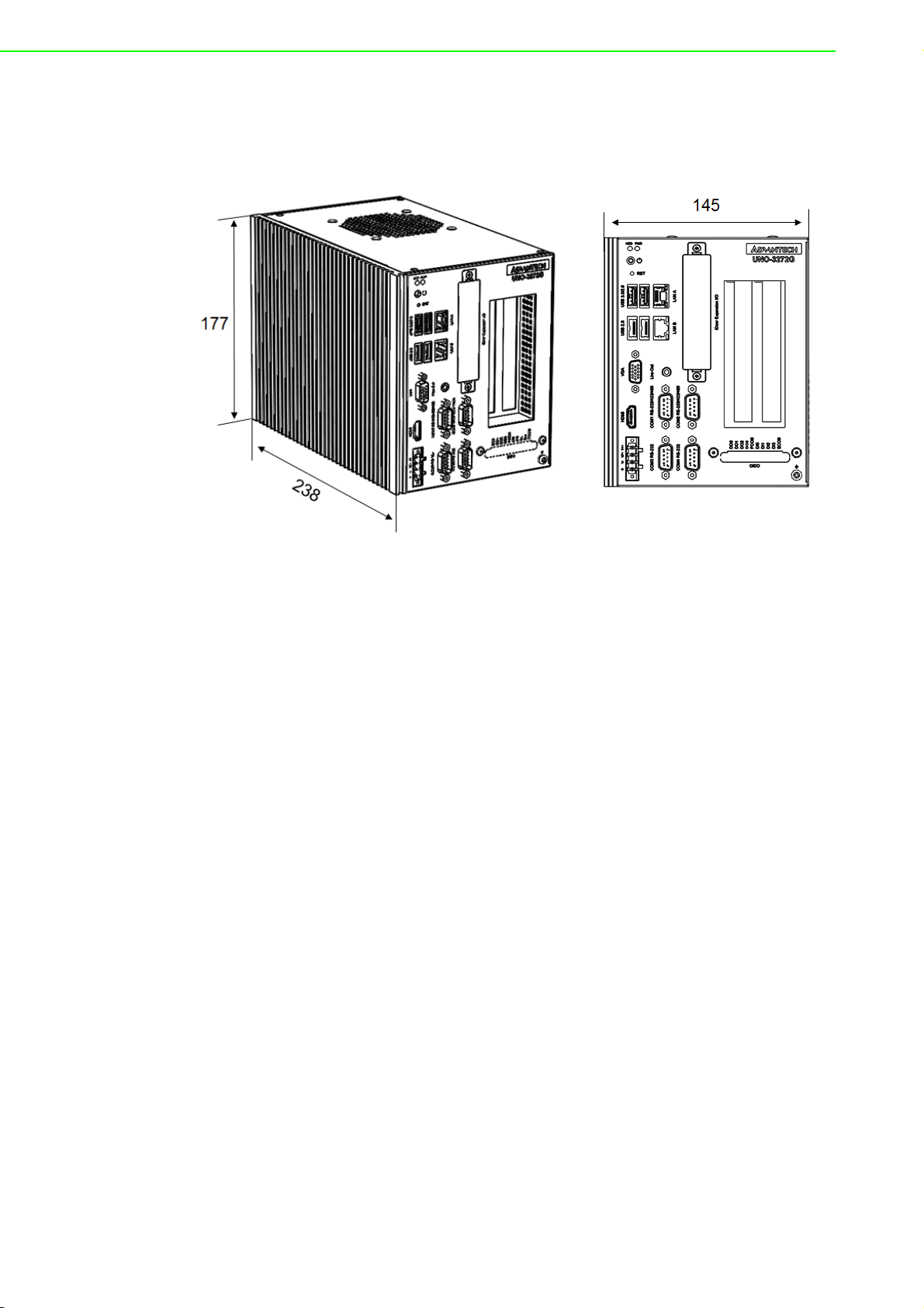
1.4 Mechanical Specifications
1.4.1 Dimensions
Figure 1.1 Dimensions
1.4.2 Weight
2.6 kg
1.5 Power Requirements
1.5.1 System power
DC 10-36V
DC
1.5.2 RTC battery
BR2032 3 V/190 mAh
1.6 Environment Specification
1.6.1 Operating temperature
-20 ~ 60 °C with 0.7m/sec air flow: with 1x Industrial SSD without PCI/PCIe expansion boards
1.6.2 System safety certification test temperature
0 ~ 40 °C with 2.5” HDD
1.6.3 Relative humidity
95% @ 40 °C (non-condensing)
1.6.4 Storage temperature
-40 ~ 85 °C (-40 ~ 185 °F)
UNO-3272G User Manual 4
Page 15

1.6.5 Vibration during operation
When system is equipped with SSD only: 2 Grms, IEC 60068-2-64, random, 5 ~
500 Hz, 1 Oct/min., 1 hr/axis, x,y,z 3 axes.
When system is equipped with 2.5-inch HDD: 0.5 Grms, IEC 60068-2-64, ran-
dom, 5 ~ 500 Hz, 1 Oct/min., 1 hr/axis, x,y,z 3 axes.
1.6.6 Shock during operation
When system is equipped with SSD only: 30 G, IEC 60068-2-27, half sine, 11 ms
duration.
1.6.7 Safety
UL/CB, CCC, BSMI
1.6.8 EMC
CE, FCC, CCC, BSMI
Chapter 1 Overview
5 UNO-3272G User Manual
Page 16

UNO-3272G User Manual 6
Page 17

Chapter 2
2 H/W Installation
This chapter introduces external
IO and the installation of UNO3272G hardware.
Page 18
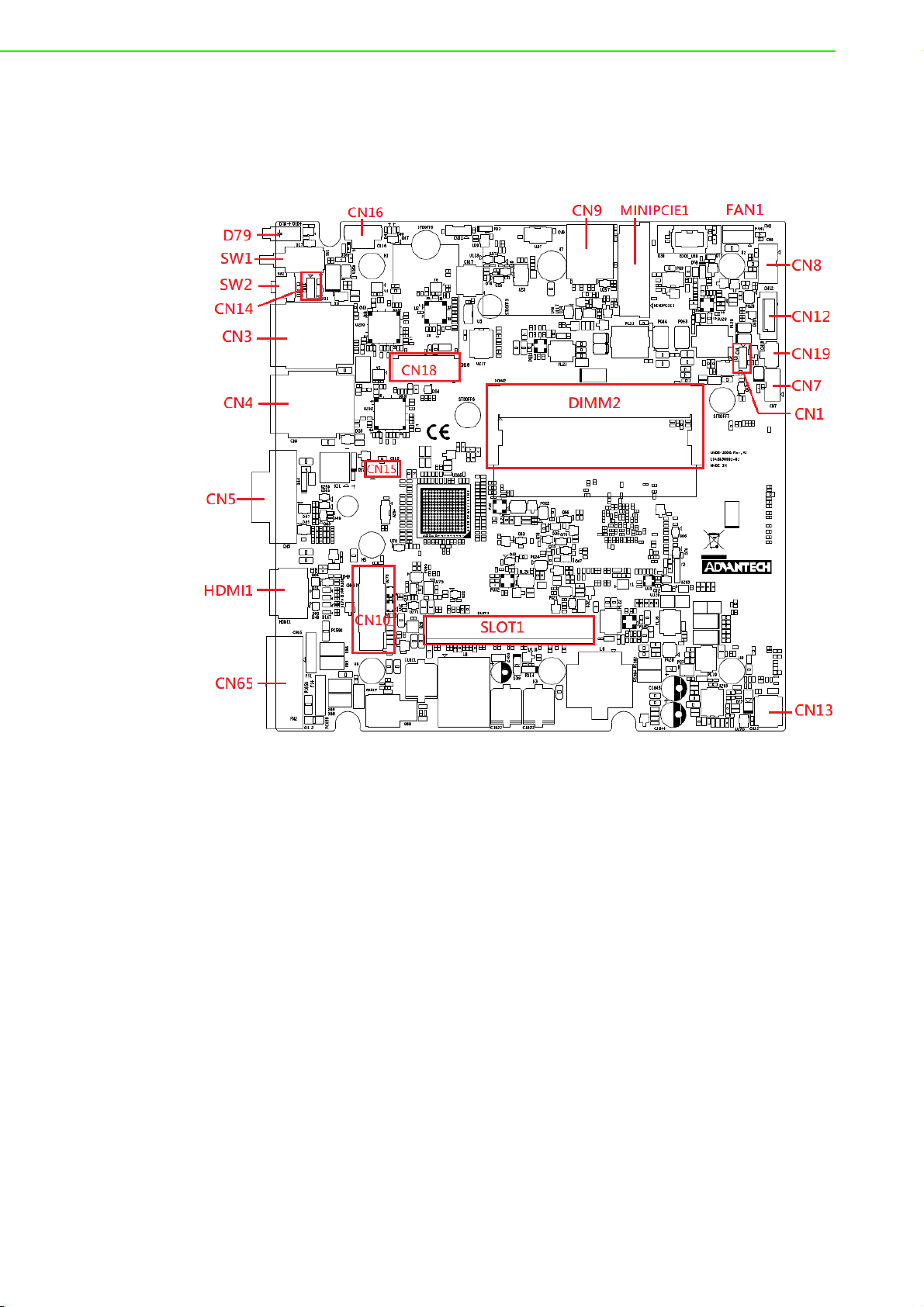
2.1 Introduction
The following sections show the internal jumper settings and the external connectors
and pin assignments.
Figure 2.1 Motherboard Connector and jumper locations (top side)
UNO-3272G User Manual 8
Page 19
Chapter 2 H/W Installation
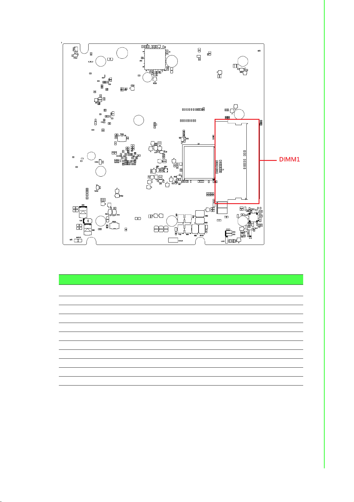
Figure 2.2 Motherboard Connector and jumper locations (rear side)
Table 2.1: Motherboard Connector
Location Function Location Function
CN3 LANA+USB3.0/2.0 CN16 Internal Power Switch/Reset
CN4 LANB+USB2.0 CN18 M.2
CN5 VGA CN65 Power Input
CN7 Internal USB2.0 MPCIE1 Mini PCIe
CN8 SATA Power SLOT1 PCIE Slot
CN9 SIM Holder D79 Power/SATA status LED
CN10 COM1/2/3/4+Audio SW1 Power Switch
CN12 SATA SW2 Reset
CN13 DIDO DIMM1 DDR Slot1
CN15 Inverter Power DIMM2 DDR Slot2
9 UNO-3272G User Manual
Page 20
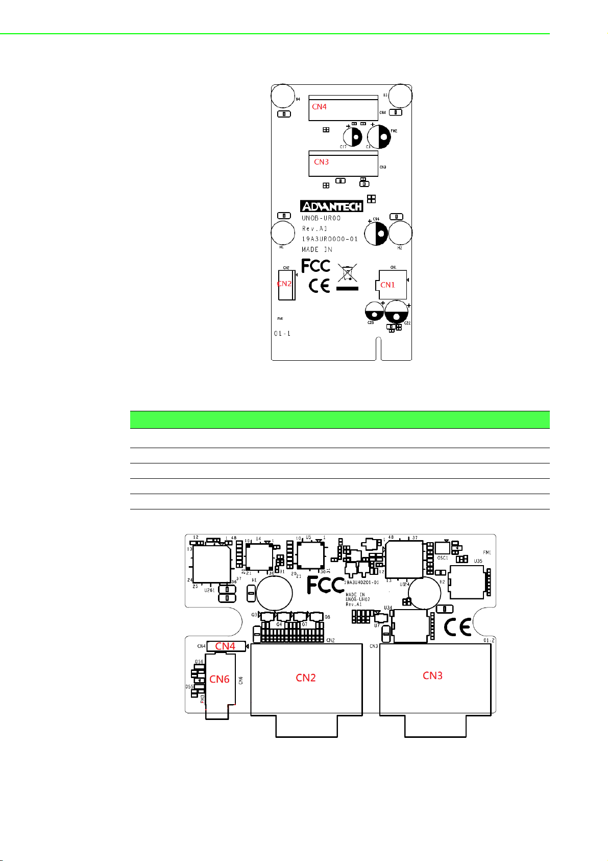
Figure 2.3 PCIe card connector locations
Table 2.2: PCIE Connector
Location Function
CN1 12V Power Output
CN2 5V&12V Power Output
CN3 PCIE2
CN4 PCIE1
Figure 2.4 COM card connector locations
UNO-3272G User Manual 10
Page 21

Table 2.3: COM Connector
Location Function
CN2 COM1/COM2
CN3 COM3COM4
CN4 MIC IN
CN6 LINE Out
2.2 Jumpers
Configure the UNO-3272G to match the needs of your application by setting jumpers.
To close a jumper, you connect the pins with the clip. To open a jumper, you remove
the clip. Sometimes a jumper will have three pins, labeled 1, 2 and 3. In this case you
would connect either pins 1 and 2, or 2 and 3.
Chapter 2 H/W Installation
The jumper settings are schematically depicted in this manual as follows.
A pair of needle-nose pliers may be helpful when working with jumpers. If you have
any doubts about the best hardware configuration for your application, contact your
local distributor or sales representative before you make any changes. Generally, you
simply need a standard cable to make most connections.
2.2.1 Jumper list
Table 2.4: Jumper List (motherboard)
Location Function
CN1 Clear CMOS
CN14 System AT/ATX mode option
11 UNO-3272G User Manual
Page 22

2.2.1.1 Clear CMOS
UNO-3272G mainboard contains a jumper that can erase CMOS data and reset the
system BIOS information. Normally this jumper should be set with pins 1-2 closed. If
you want to reset the CMOS data, set CMOS1 to 2-3 closed for just a few seconds,
and then move the jumper back to 1-2 closed. This procedure will reset the CMOS to
its default setting.
CMOS1 Clear CMOS
Footprint 3x1 Pin
Setting Function Function
(1-2) Normal (default)
(2-3) Clear CMOS
2.2.1.2 System AT/ATX mode function option
UNO-3272G supports AT or ATX mode and default is ATX module. If you want to
change to AT mode you can find AT/ATX mode jumper on the motherboard.
PSON1 System AT/ATX mode option
FootPrint 3x1 Pin
Setting Function Function
(1-2) AT mode
(2-3) ATX mode
2.3 Connectors
2.3.1 External I/O Connectors
Figure 2.5 UNO-3272G Front View
UNO-3272G User Manual 12
Page 23

2.3.1.1 COM connector
UNO-3272G provides four 9-pin D-sub connectors, two of which offer RS-232/422/
485 and the other two offer RS-232 serial communication interface ports. Default setting is RS-232, but this can be modified by BIOS setting. You can find detailed setting
methods in Chapter 3.
Table 2.5: COM Connector Pin Assignments
RS-232 RS-422 RS-485
Pin Signal Name Signal Name Signal Name
1 DCD TX- DATA2 RXD TX+ DATA+
3TXD RX+ 4DTR RX- 5GND GND GND
6DSR - 7RTS - 8CTS - 9RI - -
Chapter 2 H/W Installation
Figure 2.6 COM Connector
Note! NC represents "No Connection".
13 UNO-3272G User Manual
Page 24

2.3.1.2 Ethernet connector (LAN)
UNO-3272G is equipped with two Ethernet controllers that are fully compliant with
IEEE 802.3u 10/100/1000 Mbps CSMA/CD standards. LANA &LANB are equipped
with Intel i211. The Ethernet port provides a standard RJ45 jack connector with LED
indicators on the front side to show its Active/Link status and Speed status.
Table 2.6: Ethernet Connector Pin Assignments
Pin Signal Name Description
1MDI0+ In BASE-T: Media Dependent Interface[0]:
2MDI0-
3MDI1+ In BASE-T: Media Dependent Interface[1]:
6MDI1-
4MDI2+ In BASE-T: Media Dependent Interface[3:2]:
5MDI27MDI3+
8MDI3-
Figure 2.7 LAN Connector
1000BASE-T: In MDI configuration, MDI[0]+/-
corresponds to BI_DA+/- and in MDI-X configuration MDI[0]+/- corresponds to BI_DB+/-.
10BASE-T and 100BASE-TX: In MDI configura-
tion, MDI[0]+/- is used for the transmit pair and in
MDIX configuration MDI[0]+/- is used for the
receive pair.
1000BASE-T: In MDI configuration, MDI[1]+/corresponds to BI_DB+/- and in MDI-X configuration MDI[1]+/- corresponds to BI_DA+/-.
10BASE-T and 100BASE-TX: In MDI configura-
tion, MDI[1]+/- is used for the receive pair and in
MDI-X configuration MDI[1]+/- is used for the
transmit pair.
1000BASE-T: In MDI and in MDI-X configuration,
MDI[2]+/- corresponds to BI_DC+/- and MDI[3]+/
- corresponds to BI_DD+/-.
100BASE-TX: Unused.
10BASE-T: Unused.
Table 2.7: LED Indicators
Left LED Right LED
10 Link 100 Left 1000 Link Active
Off Orange Green Green
UNO-3272G User Manual 14
Page 25

2.3.1.3 Audio connector
UNO-3272G has only one stereo audio ports with phone jack connectors- Line_Out.
The audio chip is controlled by ACL888-VD2, and it's compliant with AZALIA standard.
Table 2.8: Audio Connector Pin Assignments
Pin Audio signal Name
1 Line_out
2.3.1.4 USB 3.0 connector
UNO-3272G provides one USB 3.0 & three USB2.0 interface connectors, which give
complete Plug & Play and hot swapping for up to 127 external devices. The USB
interface complies with USB XHCI, Rev. 3.0. Please refer to the table below for pin
assignments.
Chapter 2 H/W Installation
Figure 2.8 Audio Connector
Figure 2.9 USB 2.0 Connector
Table 2.9: USB 2.0 connector Pin Assignments
1VCC
2DATA3DATA+
4GND
Figure 2.10 USB 3.0 Connector
Table 2.10: USB 3.0 connector Pin Assignments
1VCC
2 USB Data 3 USB Data +
4GND
5 SSRX6 SSRX+
7GND
8 SSTX9 SSTX+
15 UNO-3272G User Manual
Page 26

2.3.1.5 VGA connector
The UNO-3272G provides a high resolution VGA interface with a 15-pin D-sub connector to support a VGA CRT monitor. It supports display resolution of up to1920 x
1080 @ 60 Hz.
Table 2.11: VGA Connector Pin Assignments
Pin Signal Name Pin Signal Name
1Red 2 Green
3 Blue 4 NC
5GND 6 GND
7GND 8 GND
9+5V 10GND
11 NC 12 DDC_DAT
13 H-SYNC 14 V-SYNC
15 DDC_CLK
Figure 2.11 VGA Connector
2.3.1.6 HDMI Connector
UNO-3272G provides a high resolution HDMI, It supports display resolution of up to
1920 x 1080 @ 60 Hz.
Table 2.12: HDMI Connector Pin Assignments
Pin Signal Name Pin Signal Name
1 TMDS Data2+ 2 TMDS Data2 Shield
3 TMDS Data2- 4 TMDS Data1+
5 TMDS Data1 Shield 6 TMND Data17 TMDS Data0+ 8 TMDS Data0 Shield
9 TMDS Data0- 10 TMDS Clock+
11 TMDS Clock Shield 12 TMDS Clock13 NL 14 Reserved
15 SCL 16 SDA
17 DDC/CEC/HEC Gound 18 +5V Power (max 50mA)
19 Hot Plug Detect
Figure 2.12 HDMI Connector
UNO-3272G User Manual 16
Page 27

2.3.1.7 Power Input Connector
UNO-3272G comes with a four-pin header as default that carries 10VDC - 36VDC
external dual power input. This product is intended to be supplied by a UL Listed DC
Power Source, rated 10-36Vdc, 6.5-1.8A and Tma 40 degree C, if need further assistance, please contact Advantech for further information (Ensure to connect the power
cord to a socket-outlet with earthing connection).
Chapter 2 H/W Installation
Figure 2.13 Power Connector
Table 2.13: Pin Assignments for Power Connector Pin Header
Pin Signal Name
1 +VDC1
2 +VDC2
3 GND (Power GND)
4 Chassis GND
2.3.1.8 Power ON/OFF button & LED indicators
UNO-3272G comes with a Power On/ Off button with LED indicators on the front side
to show its On status (Green LED) and Off/Suspend status (Yellow LED), that supports dual function of Soft Power-On/Off and suspend.
2.3.1.9 Digital power input/ output (Optional)
UNO-3272G provide optional DI/O functions by ordering additional P/N: UNO-3000DIOAE.
Table 2.14: DI/ DO Pin Assignments
Pin Signal Name Description
1 DO0 Isolated digital output
2 DO1 Isolated digital output
3 DO2 Isolated digital output
4 DO3 Isolated digital output
5 PCOM Freewheeling common diode for IDO
17 UNO-3272G User Manual
Page 28

Table 2.14: DI/ DO Pin Assignments
6 DI0 Isolated digital input
7 DI1 Isolated digital input
8 DI2 Isolated digital input
9 DI3 Isolated digital input
10 DGND External common of IDI0~3
Table 2.15: DI/DO switch
Dry Contact Wet Contact
1OFF ON
2ON OFF
Default: Dry contact
Isolated Digital Input Each of the 4 isolated digital input channels accept voltages
from 0 to 30 V. Every four input channels share one external common. (Pin1-4 use
PCOM and DGND, Pin 6-9 use DGND) The following figure shows how to connect an
external input source to the card's isolated inputs.
Figure 2.14 Isolated DI Dry connection
UNO-3272G User Manual 18
Page 29

Figure 2.15 Isolated DI Wet connection
Isolated Digital Output If the external voltage source (5~40 V) is connected to each
isolated output channel (IDO) and its isolated digital output turns on (200 mA max./
ch), the card's current will sink from the external voltage source. The following figure
shows how to connect an external output load to the card's isolated outputs.
Chapter 2 H/W Installation
Figure 2.16 Isolated Digital Output Connection
19 UNO-3272G User Manual
Page 30

2.3.2 Internal I/O Connectors
Table 2.16: PCIE Connector Pin Assignments
CN1 CN2 FAN1
Pin Signal Name Signal Name Signal Name
1GND +V12 +V12
2 GND GND GND
3 +V12 GND NC
4+V12 +5V
2.4 Installation
2.4.1 HDD installation
UNO-3272G supports 1 HDD/ SDD installation. The following steps demonstrate how
to install 2.5” storage.
1. Remove 8 screws from top and side cover of UNO
UNO-3272G User Manual 20
Page 31

2. Remove the 4 screws on rear cover of UNO.
Chapter 2 H/W Installation
3. Take off the HDD/SSD tray from rear cover inside.
21 UNO-3272G User Manual
Page 32

4. Secure the HDD with 4 pcs reserved screws in the accessory package.
5. Slide down the tray and replace all the screws and put the cover back.
UNO-3272G User Manual 22
Page 33

2.4.2 Memory & M.2 storage installation
UNO-3272G has default build-in 4G RAM, but can support up to 8GB by adding additional 4G Memory; UNO-3272G also provides M.2 B-key storage with up to 512 GB.
Following steps demonstrate how to install additional RAM and M.2 Storage.
1. Remove the 8 screws from the top and side cover of UNO, install the RAM mod-
ule and M.2 storage as below:
Chapter 2 H/W Installation
2. Replace all screws and put the cover back.
23 UNO-3272G User Manual
Page 34

2.4.3 iDOOR Installation
UNO-3272G supports 1 x iDOOR expansion by utilizing the mPCIe interface. The following steps demonstrate how to install the iDOOR module with the mPCIe card.
1. Remove 8 screws from top and side cover of UNO, install the mPCIe module as
below:
2. Remove iDOOR screws on front panel and take off the iDOOR plate from UNO.
3. Remove the iDOOR plate and attach the iDOOR module you selected.
4. Screw back the iDOOR module back on UNO.
UNO-3272G User Manual 24
Page 35

Chapter 2 H/W Installation
2.4.4 DI/O card Installation (Optional)
UNO-3272G allows 4 x DI/DO by ordering additional DIO cards (PN: UNO-3000DIOAE). Follow these steps to demonstrate how to install a DI/O card.
1. Remove the rubber and punch out from the reserved DI/O holes.
25 UNO-3272G User Manual
Page 36

2. Fix the DI/O card by replacing the 2 screws on accessory package.
3. Connect DI/O cable as below (Motherboard: CN13).
UNO-3272G User Manual 26
Page 37

2.4.5 PCI/ PCIe Installation (Optional)
UNO-3272G provides 2 x PCIex1 expansion slots for add-on cards. Follow the steps
for how to install add-on cards.
1. Remove 8 screws from the top and side cover of UNO as well as the PCI/PCIe
bracket.
Chapter 2 H/W Installation
2. Plug in add-on card as below and fix the card by replacing the screws.
27 UNO-3272G User Manual
Page 38

2.4.6 FAN-kit Installation (Optional)
The following steps demonstrate how to install an optional fan kit (PN: UNO-3000FANAE)
1. Remove 8 screws from the top and side cover of UNO and take out the filter.
2. Remove 4 screws on the top cover.
UNO-3272G User Manual 28
Page 39

3. Fix the fan-kit by replacing the 4 screws.
4. Connect power cable as below.
Chapter 2 H/W Installation
29 UNO-3272G User Manual
Page 40

2.4.7 Riser card (change) Installation
UNO-3272G provides other riser cards (2 x PCI) for different applications.
1. Pull out the current riser card and remove the copper pillars from the chassis.
2. Plug in the new riser card then replace the 5 screws.
UNO-3272G User Manual 30
Page 41

2.4.8 Mounting kit Installation (Optional)
UNO-3272G supports wall mount and stand mount. Optional mounts (PN:UNO-3000WMKAE).
2.4.8.1 Wall Mounting
1. Remove the screws from UNO chassis then fix the mounting kit on UNO using
the same screws (M4*5L*4 Pcs).
Chapter 2 H/W Installation
2. Install UNO-3272G on the wall by replacing the 4 screws.
31 UNO-3272G User Manual
Page 42

2.4.8.2 Stand Mounting
1. Remove the screws from the UNO chassis then fix the mounting kit on UNO
using same screws.
2. Install UNO-3272G by replacing the 4 screws
UNO-3272G User Manual 32
Page 43

Chapter 3
3 AMI BIOS Setup
This chapter introduces how to
set BIOS configuration data.
Page 44

3.1 Introduction
With the AMI BIOS Setup program, you can modify BIOS settings and control the
special features of your computer. The Setup program uses a number of menus for
making changes and turning special features on or off. This chapter describes the
basic navigation of the UNO-3272G setup screens.
3.2 Entering Setup
Press the "Del" or "Esc." key during the Power On Self Test (POST) process to enter
the BIOS setup screen, otherwise the system will continue the POST process.
3.2.1 Main Setup
When you first enter the BIOS Setup Utility, you will enter the Main setup screen. You
can always return to the Main setup screen by selecting the Main tab. There are two
Main Setup options. They are described in this section. The Main BIOS Setup screen
is shown below.
UNO-3272G User Manual 34
Page 45

The Main BIOS setup screen has two main frames. The left frame displays all the
options that can be configured. Grayed-out options cannot be configured; options in
blue can. The right frame displays the key legend.
Above the key legend is an area reserved for a text message. When an option is
selected in the left frame, it is highlighted in white. Often a text message will accompany it.
System Time / System Date
Use this option to change the system time and date. Highlight System Time or
System Date using the <Arrow> keys. Enter new values through the keyboard.
Press the <Tab> key or the <Arrow> keys to move between fields. The date
must be entered in MM/DD/YY format. The time must be entered in HH:MM:SS
format.
3.2.2 Advanced BIOS Features Setup
Select the Advanced tab from the UNO-3272G setup screen to enter the Advanced
BIOS Setup screen. You can select any of the items in the left frame of the screen,
such as ACPI Settings and hit <enter> to go to the sub menu for that item. You can
display an Advanced BIOS Setup option by highlighting it using the <Arrow> keys. All
Advanced BIOS Setup options are described in this section. The Advanced BIOS
Setup screen is shown below. The sub menus are described on the following pages.
Chapter 3 AMI BIOS Setup
35 UNO-3272G User Manual
Page 46

3.2.2.1 Trusted Computing
Security Device Support
This item allows users to enable or disable "Security Device Support".
3.2.2.2 ACPI Settings
Enable ACPI Auto Configuration
This item allows users to enable or disable “ACPI Auto Configuration”.
UNO-3272G User Manual 36
Page 47

Enable Hibernation
This item allows users to enable or disable “Hibernation”.
ACPI Sleep State
This item allows users to set ACPI mode S3 (Suspend to RAM) or to Disable
“ACPI Sleep State”.
Lock Legacy Resources
This item allows users to enable or disable “Lock Legacy Resources”
3.2.2.3 IT8768E Super IO Configuration
UNO-3272G supports 2xRS-232/422/485 & 2-RS-232.
Chapter 3 AMI BIOS Setup
37 UNO-3272G User Manual
Page 48

Serial Port 1 Configuration
– Serial Port
This item allows users to enable or disable for "Serial Port".
– Change Settings
This item allows users to Change Settings of Serial Ports. The default setting is
"RS-232".
UNO-3272G User Manual 38
Page 49

– Device Mode
This item allows users to set the mode to RS-422/485. The default setting is
"RS232".
Serial Port 2 Configuration
– Serial Port
This item allows users to enable or disable for "Serial Port".
– Change Settings
This item allows users to change settings of serial ports. The default setting is
"Auto".
– Device Mode
This item allows users to set the mode to RS-422/485. The default setting is
"RS232".
Chapter 3 AMI BIOS Setup
39 UNO-3272G User Manual
Page 50

Serial Port 3 Configuration
– Serial Port
This item allows users to enable or disable for "Serial Port".
– Change Settings
This item allows users to Change Settings of Serial Ports. The default setting is
"Auto".
Serial Port 4 Configuration
– Serial Port
This item allows users to enable or disable for "Serial Port".
– Change Settings
This item allows users to change settings of serial ports. The default setting is
"Auto".
UNO-3272G User Manual 40
Page 51

3.2.2.4 Embedded Controller Configuration
Chapter 3 AMI BIOS Setup
iManager WatchDog IRQ
This item allows users to enable or disable for "iManager WatchDog IRQ"
3.2.2.5 S5 RTC Wake Settings
Wake system from S5
This item allows users to enable or disable for "Wake system from S5"
41 UNO-3272G User Manual
Page 52

3.2.2.6 CPU Configuration
Execute Disable Bit
This item allows users to enable or disable for "Execute Disable Bit".
Intel Virtualization Technology
This item allows users to enable or disable for "Intel Virtualization Technology".
UNO-3272G User Manual 42
Page 53

3.2.2.7 IDE Configuration
Chapter 3 AMI BIOS Setup
3.2.2.8 Miscellaneous Configuration
OS Selection:
This items allow user to set the OS mode: "Win 8.x" or "Win 7"or “WinCE 7". (If
user installs Win 10 or Linux OS, set for "Win8.x")
43 UNO-3272G User Manual
Page 54

3.2.2.9 LAN Controller
LAN Controller
This items allowed user to enable or disable for wake on LAN function
3.2.2.10 Network Stack Configuration
UNO-3272G User Manual 44
Page 55

Network Stack
This item allows users to enable or disable for "Network Stack" (For using UEFI
PXE function, please enable this item).
3.2.2.11 CSM Configuration
Chapter 3 AMI BIOS Setup
CSM Support
This item allows users to enable or disable for "CSM Support".
GateA20 Active
This item allows users to set Upon Request or Always for "GateA20 Active".
Option ROM Messages
This item allows users to set Force BIOS or Keep Current for "Option ROM
Messages".
Boot option filter
This item allows users to set UEFI and Legacy or Legacy only or UEFI only for
"Boot option filter". (For using Legacy PXE function, please set to "UEFI" or"
UEFI and Legacy" mode.)
Network
This item allows users to set Do not launch or UEFI or Legacy for "Network".
(For using Legacy PXE function, please set to "UEFI" mode.)
Storage
This item allows users to set Do not launch or UEFI or Legacy for "Storage".
Video
This item allows users to set Do not launch or UEFI or Legacy for "Video".
Other PCI devices
This item allows users to set Do not launch or UEFI or Legacy for "Other PCI
devices".
45 UNO-3272G User Manual
Page 56

3.2.2.12 USB Configuration
Legacy USB Support
This item allows users to enable or disable or set Auto for "Legacy USB Support".
XHCI Hand-off
This item allows users to enable or disable "XHCI Hand-off".
EHCI Hand-off
This item allows users to enable or disable "EHCI Hand-off".
USB Mass Storage Driver Support
This item allows users to enable or disable "USB Mass Storage Driver Support".
USB transfer Time-out
This item allows users to set different time mode for "USB transfer Time-out".
Device reset Time-out
This item allows users to set different time modes for "Device reset Time-out".
Device power-up delay
This item allows users to set different time mode for "Device power-up delay".
Kingston DataTraveler 3.0MAP
This item allows users to set different time mode for "Kingston DataTraveler
3.0MAP".
UNO-3272G User Manual 46
Page 57

3.2.3 Chipset
Chapter 3 AMI BIOS Setup
47 UNO-3272G User Manual
Page 58

3.2.3.1 USB Configuration
USB Per port control
This item allows users to enable or disable for "USB Per port control".
UNO-3272G User Manual 48
Page 59

3.2.3.2 PCI Express Configuration
Chapter 3 AMI BIOS Setup
3.2.4 Security
Set Admin Password
This item allows users to set "Administrator Password" if desired.
49 UNO-3272G User Manual
Page 60

3.2.5 Boot
Setup Prompt Timeout
Number of Seconds to wait for setup activation kay. 65535 (0xFFFF) means
indefinite waiting.
Bootup NumLock State
This item allows users to set "Bootup NumLock State" either On or Off.
Quiet Boot
This item allows users to disable or enable "Quiet Boot".
Boot Option Priorities
These items will display based on how many devices are attached
UNO-3272G User Manual 50
Page 61

Chapter 3 AMI BIOS Setup
3.2.6 Save & Exit
Save Changes and Exit
This item allows users to Save Changes and Exit.
Discard Changes and Exit
This item allows users to Discard Changes and Exit.
51 UNO-3272G User Manual
Page 62

Save Changes and Reset
This item allows users to Save Changes and Reset.
Discard Changes and Reset
This item allows users to Discard Changes and Reset.
Save Changes
This item allows users to Save Changes.
Discard Changes
This item allows users to Discard Changes.
Restore Defaults
This item allows users to restore factory defaults.
Save as User Defaults
This item allows users to Save as User Defaults.
Restore User Defaults
This item allows users to Restore User Defaults.
Launch EFI Shell from file system device
Attempts to Launch EFI Shell application (Shell.efi) form one of the available file
system devices.
UNO-3272G User Manual 52
Page 63

Chapter 3 AMI BIOS Setup
53 UNO-3272G User Manual
Page 64

www.advantech.com
Please verify specifications before quoting. This guide is intended for reference
purposes only.
All product specifications are subject to change without notice.
No part of this publication may be reproduced in any form or by any means,
electronic, photocopying, recording or otherwise, without prior written permission of the publisher.
All brand and product names are trademarks or registered trademarks of their
respective companies.
© Advantech Co., Ltd. 2019
 Loading...