

Page 1

PPC-150
Pentium® MMX processor-based
panel PC with 15" LCD flat panel
display
Page 2

Copyright Notice
This document is copyrighted, 1999, by Advantech Co. Ltd. All rights are
reserved. Advantech Co., Ltd. reserves the right to alter the products
described in this manual at any time without notice.
No part of this manual may be reproduced, copied, translated or
transmitted in any form or by any means without the prior written
permission of Advantech. Information provided in this manual is intended
to be accurate and reliable. However, Advantech assumes no responsibility
for use of this manual, nor for any infringements upon the rights of third
parties which may result from such use.
All brand and product names mentioned herein are trademarks or
registered trademarks of their respective holders.
Part No. 2002015000
1st Edition Printed in Taiwan June 1999
ii
Page 3

FCC Class B
This equipment has been tested and found to comply with the limits for a
Class B digital device, pursuant to Part 15 of the FCC Rules. These limits
are designed to provide reasonable protection against harmful interference
when the equipment is operated in a residential environment. This
equipment generates, uses and can radiate radio frequency energy. If not
installed and used in accordance with this user's manual, it may cause
harmful interference to radio communications. Note that even when this
equipment is installed and used in accordance with this user's manual,
there is still no guarantee that interference will not occur. If this
equipment is believed to be causing harmful interference to radio or
television reception, this can be determined by turning the equipment on
and off. If interference is occurring, the user is encouraged to try to correct
the interference by one or more of the following measures:
• Reorient or relocate the receiving antenna
• Increase the separation between the equipment and the receiver
• Connect the equipment to a power outlet on a circuit different from that
to which the receiver is connected
• Consult the dealer or an experienced radio/TV technician for help
Warning: Any changes or modifications made to the equipment
which are not expressly approv ed by the relevant
standards authority could void your authority to operate
the equipment.
iii
Page 4

Packing List
Before installing your panel PC, ensure that the following materials have
been received:
• PPC-150 series panel PC
• User's manual
• Accessories for PPC-150
- Y-shaped adapter for PS/2 mouse and AT keyboard
- Power cord (1.8 m) - USA type (other types are available on request)
- Floppy disk with CD-ROM drive driver
- "PPC-150 Drivers and Utilities" CD-ROM disc
- Mounting kits and packet of screws
- Heat sink with CPU fan (optional) (refer to Notes 1 and 2)
If any of these items are missing or damaged, contact your distributor or
sales representative immediately .
Note 1: If the unit you hav e bought is basic (i.e. without a CPU ,
HDD , or SDRAM), you will find this optional item in the
accessory box.
Note 2: If you install an Intel P entium® MMX processor yourself,
you must install a heat sink with a CPU f an above the
CPU. This procedure will a v oid heat damage to the
CPU.
iv
Page 5

Additional Information and Assistance
1. Visit the Advantech Web sites at www.advantech.com or
www.advantech.com.tw where you can find the latest information
about the product.
2. Contact your distributor, sales representative, or Advantech's customer
service center for technical support if you need additional assistance.
Please have the following information ready before you call:
• Product name and serial number
• Description of your peripheral attachments
• Description of your software (operating system, version, application
software, etc.)
• A complete description of the problem
• The exact wording of any error messages
v
Page 6

Safety Instructions
1. Read these safety instructions carefully.
2. Keep this User's Manual for later reference.
3. Disconnect this equipment from any AC outlet before cleaning. Use a damp cloth.
Do not use liquid or spray detergents for cleaning.
4. For plug-in equipment, the power outlet socket must be located near the
equipment and must be easily accessible.
5. Keep this equipment away from humidity.
6. Put this equipment on a reliable surface during installation. Dropping it or letting
it fall may cause damage.
7. The openings on the enclosure are for air convection. Protect the equipment from
overheating. DO NOT COVER THE OPENINGS.
8. Make sure the voltage of the power source is correct before connecting the
equipment to the power outlet.
9. Position the power cord so that people cannot step on it. Do not place anything
over the power cord.
10. All cautions and warnings on the equipment should be noted.
11. If the equipment is not used for a long time, disconnect it from the power source
to avoid damage by transient overvoltage.
12. Never pour any liquid into an opening. This may cause fire or electrical shock.
13. Never open the equipment. For safety reasons, the equipment should be opened
only by qualified service personnel.
14. If one of the following situations arises, get the equipment checked by service
personnel:
a. The power cord or plug is damaged.
b. Liquid has penetrated into the equipment.
c. The equipment has been exposed to moisture.
d. The equipment does not work well, or you cannot get it to work according to
the user's manual.
e. The equipment has been dropped and damaged.
f. The equipment has obvious signs of breakage.
15. DO NOT LEAVE THIS EQUIPMENT IN AN UNCONTROLLED
ENVIRONMENT WHERE THE STORAGE TEMPERATURE IS BELOW
-20° C (-4° F) OR ABOVE 60° C (140° F). THIS MA Y DAMAGE THE EQUIPMENT.
The sound pressure level at the operator's position according to IEC 704-1:1982 is
no more than 70dB(A).
DISCLAIMER: This set of instructions is given according to IEC 704-1. Advantech
disclaims all responsibility for the accuracy of any statements contained herein.
vi
Page 7

Wichtige Sicherheishinweise
1. Bitte lesen sie Sich diese Hinweise sorgfältig durch.
2. Heben Sie diese Anleitung für den späteren Gebrauch auf.
3. Vor jedem Reinigen ist das Gerät vom Stromnetz zu trennen. Verwenden Sie
Keine Flüssig-oder Aerosolreiniger. Am besten dient ein angefeuchtetes Tuch
zur Reinigung.
4. Die NetzanschluBsteckdose soll nahe dem Gerät angebracht und leicht
zugänglich sein.
5. Das Gerät ist vor Feuchtigkeit zu schützen.
6. Bei der Aufstellung des Gerätes ist auf sicheren Stand zu achten. Ein Kippen
oder Fallen könnte Verletzungen hervorrufen.
7. Die Belüftungsöffnungen dienen zur Luftzirkulation die das Gerät vor
überhitzung schützt. Sorgen Sie dafür, daB diese Öffnungen nicht abgedeckt
werden.
8. Beachten Sie beim. AnschluB an das Stromnetz die AnschluBwerte.
9. Verlegen Sie die NetzanschluBleitung so, daB niemand darüber fallen kann.
Es sollte auch nichts auf der Leitung abgestellt werden.
10. Alle Hinweise und Warnungen die sich am Geräten befinden sind zu beachten.
11. Wird das Gerät über einen längeren Zeitraum nicht benutzt, sollten Sie es vom
Stromnetz trennen. Somit wird im Falle einer Überspannung eine
Beschädigung vermieden.
12. Durch die Lüftungsöffnungen dürfen niemals Gegenstände oder Flüssigkeiten
in das Gerät gelangen. Dies könnte einen Brand bzw. elektrischen Schlag
auslösen.
13. Öffnen Sie niemals das Gerät. Das Gerät darf aus Gründen der elektrischen
Sicherheit nur von authorisiertem Servicepersonal geöffnet werden.
14. Wenn folgende Situationen auftreten ist das Gerät vom Stromnetz zu trennen
und von einer qualifizierten Servicestelle zu überprüfen:
a - Netzkabel oder Netzstecker sind beschädigt.
b - Flüssigkeit ist in das Gerät eingedrungen.
c - Das Gerät war Feuchtigkeit ausgesetzt.
d - Wenn das Gerät nicht der Bedienungsanleitung entsprechend funktioni
ert oder Sie mit Hilfe dieser Anleitung keine Verbesserung erzielen.
e - Das Gerät ist gefallen und/oder das Gehäuse ist beschädigt.
f - Wenn das Gerät deutliche Anzeichen eines Defektes aufweist.
Der arbeitsplatzbezogene Schalldruckpegel nach DIN 45 635 Teil 1000
beträgt 70dB(A) oder weiger.
DISCLAIMER: This set of instructions is given according to IEC704-1. Advantech disclaims all
responsibility for the accuracy of any statements contained herein.
vii
Page 8

Contents
Chapter 1 General Information 1
1.1 Introduction...................................................................2
1.2 How to Use This Manual...............................................4
1.3 Specifications................................................................6
General ..........................................................................................6
Standard PC functions....................................................................6
PCI SVGA/flat panel interface ........................................................7
Audio function.................................................................................7
PCI bus Ethernet interface .............................................................8
Touchscreen (optional) ...................................................................8
Optional modules ...........................................................................9
Environment ...................................................................................9
1.4 Dimensions ...................................................................10
Chapter 2 System Setup 11
2.1 A Quick Tour of the Panel PC.....................................12
2.2 Preparing For First-time Use.......................................15
2.3 Installation Procedures ............................................... 16
2.3.1 Connecting the power cord..................................................16
2.3.2 Connecting the keyboard and mouse ..................................17
2.3.3 Switching on the power........................................................17
2.4 Running the BIOS Setup Program..............................18
2.5 Installing System Software .........................................18
2.6 Installing the Drivers ...................................................19
Chapter 3 Using the Panel PC 21
3.1 Introduction.................................................................22
3.2 Floppy Drive................................................................22
3.3 CD-ROM Drive............................................................23
3.4 PCMCIA......................................................................24
viii
Page 9

3.5 PS/2 Mouse and Keyboard.........................................27
3.6 PCI/ISA Bus Expansion ..............................................27
3.7 Parallel Port ................................................................ 2 9
3.8 Serial COM Ports........................................................29
3.9 VGA Port.....................................................................30
3.10 Game Port ..................................................................30
3.11 USB Ports ...................................................................30
3.12 Audio Interface ............................................................31
3.13 Ethernet ......................................................................3 1
3.14 Adjusting the LCD Contrast and Brightness ...............31
3.15 Touchscreen (Optional) ...............................................32
Chapter 4 Hardware Installation and Upgrading 33
4.1 Overview of Hardware Installation and
Upgrading ......................................................................34
4.2 Disassembling the Panel PC ......................................35
4.3 Installing the 2.5" Hard Disk Drive (HDD) ...................37
4.4 Installing the Central Processing Unit (CPU) ..............38
4.5 Installing the SDRAM Memory Module .......................40
4.6 Installing the Floppy Disk Drive (FDD)........................41
4.7 Installing the CD-ROM Drive.......................................42
Chapter 5 Jumper Settings and Connectors 43
5.1 Jumpers and Connectors............................................44
5.1.1 Setting jumpers ...................................................................44
5.1.2 Jumpers ..............................................................................45
5.1.3 Locating jumpers .................................................................46
5.1.4 Connectors ..........................................................................47
5.1.5 Locating connectors ............................................................48
5.2 CPU Installation and Upgrading..................................49
5.2.1 System clock setting (JP1 1, JP8) ........................................49
5.2.2 CPU core voltage setting (JP13)..........................................51
5.2.3 CPU frequency ratio setting (JP14) .....................................54
5.2.4 CMOS clear for external RTC (JP12) ..................................56
ix
Page 10

5.2.5 Cyrix linear mode enable (JP10)..........................................56
5.2.6 Reset system (JP16) ...........................................................57
5.3 COM-port Interface .....................................................58
5.3.1 COM2 RS-232/422/485 setting (JP3, JP4, JP5) ..................58
5.3.2 COM3/COM4/RI pin setting (JP2, JP1) (Reserved).............59
5.4 VGA Interface .............................................................60
5.4.1 LCD panel power setting (JP6) ............................................60
5.4.2 Panel type select (JP9)........................................................61
5.5 Watchdog Timer Configuration.....................................63
5.5.1 Watchdog activity selection (JP15) ......................................63
Chapter 6 PCI Bus Ethernet Interface 65
6.1 Introduction.................................................................66
6.2 Installation of Ethernet Driver .....................................66
6.2.1 Installation for MS-DOS & WINDOWS 3.1 ..........................67
6.2.2 Installation for WINDOWS 95..............................................68
6.2.3 Installation for WINDOWS 98..............................................70
6.2.4 Installation for WINDOWS NT .............................................72
6.3 Further Information ..................................................... 74
Chapter 7 PCI SVGA Setup 75
7.1 Introduction.................................................................76
Chipset .........................................................................................76
Display memory............................................................................76
Display types ................................................................................76
7.2 Installation of SVGA driver..........................................77
7.2.1 Installation for Windows 3.1.................................................78
7.2.2 Installation for Windows 95/98.............................................80
7.2.3 Installation for Windows NT.................................................83
7.2.4 Installation for OS/2 .............................................................86
7.3 Further Information ..................................................... 88
Chapter 8 Audio 89
8.1 Introduction.................................................................90
8.2 Installation of Audio Driver..........................................90
x
Page 11

8.2.1 Installation of MS-DOS ........................................................90
8.2.2 Changing settings in DOS ...................................................91
8.2.3 Controlling volume in DOS ..................................................92
8.2.4 Installation for WINDOWS 3.1.............................................93
8.2.5 Installation for WINDOWS 95/98 .........................................94
8.2.6 Installation for WINDOWS NT .............................................96
Chapter 8 Award BIOS Setup 99
9.1 Award BIOS Setup....................................................100
9.2 CMOS Setup Utility...................................................100
9.3 Standard CMOS Setup .............................................101
9.3.1 Hard Disk Configurations...................................................102
9.4 BIOS Features Setup................................................103
9.5 Chipset Features Setup ............................................106
9.6 Power Management Setup .......................................107
9.7 PNP/PCI Configuration Setup................................... 111
9.8 Load BIOS Defaults..................................................113
9.9 Load Setup Defaults .................................................113
9.10 Integrated Peripherals .............................................. 114
9.11 Password Setting......................................................117
9.12 IDE HDD Auto Detection .......................................... 118
9.13 Save and Exit Setup .................................................119
9.14 Exit Without Saving ................................................... 119
Chapter 10 Touchscreen 121
10.1 Introduction...............................................................122
10.1.1 General information .........................................................122
10.1.2 Specifications ..................................................................122
10.1.3 Environmental specifications ...........................................122
10.2 Installation of Touchscreen Driver.............................123
10.2.2 Installation for WINDOWS 95/98 ..................................... 128
10.2.3 Installation for WINDOWS NT .........................................130
10.2.4 Installation for OS/2 (MonitorMouse) ...............................133
xi
Page 12

Appendix A LCD Specifications and Selection
Settings 139
Appendix B Programming the Watchdog Timer 141
Programming the Watchdog Timer ...................................142
Appendix C Full Disassembly Procedures 145
Appendix D in Assignments 153
IR Connector (J1) (*Reserved)..........................................154
Flat Panel Display Connector (J2).....................................155
Flat Panel Display Connector (J3).....................................156
Internal COM4 Connector (J4) ..........................................156
Touchscreen Power Connector (J5)..................................157
Sandisk SSD Connector (J6) ............................................158
EIDE Hard Disk Drive Connector (J7) ...............................159
Floppy Drive Connector (J8) .............................................160
CPU Fan Power Connector (J10)......................................161
CD-ROM Connector (J9)...................................................161
PCI/ISA Bus Expansion Connector (J11) ..........................162
Fan Power Connector (J12) ..............................................167
AT Power Connector (J13) ................................................167
Internal Speaker Connector (J15) (*Reserved) .................168
Inverter Power Connector (J16) ........................................168
COM2................................................................................169
Appendix E Mounting Instructions 171
E.1 Introduction...............................................................172
E.2 Panel Mounting.........................................................172
E.3 Desktop Stand Mounting ..........................................174
xii
Page 13

Tables
Table 5-1: Jumpers and their functions...................................................45
Table 5-2: Panel PC connectors .............................................................47
Table 5-3: System/PCI clock setting (JP11) ............................................50
Table 5-4: PCI bus clock setting (JP8)....................................................51
Table 5-5: CPU voltage setting (JP13)....................................................52
Table 5-6: CPU frequency ratio (for Intel) (JP14) ....................................54
Table 5-7: CPU frequency ratio (for AMD K6, K6-2) (JP14) ....................55
Table 5-8: Clear CMOS/External RTC (JP12).........................................56
Table 5-9: Cyrix linear mode enable (JP10) ............................................56
Table 5-10: Reset system (JP16)............................................................57
Table 5-11: COM2 RS-232/422/485 setting (JP3, JP4)...........................58
Table 5-12: COM2 RS-232/422/485 setting (JP5)...................................58
Table 5-13: PPC-150 serial port default settings.....................................59
Table 5-14: COM4/RI pin setting (JP2) ...................................................59
Table 5-15: COM3/RI pin setting (JP1) ...................................................59
Table 5-16: Panel VCC setting (JP6) ......................................................60
Table 5-17: Panel type select (JP9) ........................................................61
Table 5-18: Watchdog activity selection (JP15) ......................................63
Table A-1: PPC-150 Series LCD Specifications....................................140
Table D-1: IR Connector (J1)................................................................154
Table D-2: Flat Panel Display Connector (J2) .......................................155
Table D-3: Flat Panel Display (J3) ........................................................156
Table D-4: Internal COM4 Connector (J4) ............................................156
Table D-5: Touchscreen Power Connector (J5) ....................................157
Table D-6: Sandisk SSD Connector (J6)...............................................158
Table D-7: EIDE HDD Connector (J7) ..................................................159
Table D-8: FDD Connector (J8) ............................................................160
Table D-9: CD-ROM Connector (J9).....................................................161
Table D-10: CPU Fan Power Connector (J10)......................................161
Table D-11: PCI/ISA Slot Pin Assignments (Pins A&B)......................... 163
Table D-12: PCI/ISA Slot Pin Assignments (Pins C&D) ........................164
xiii
Page 14

Table D-13: PCI/ISA Slot Pin Assignments (Pins E&F).........................165
Table D-14: PCI/ISA Slot Pin Assignments (Pins G&H)........................166
Table D-15: Fan Power Connector (J12) ..............................................167
Table D-16: AT Power Connector (J13) ................................................167
Table D-17: Internal Speaker Connector (J15)......................................168
Table D-18: Inverter Power Connector (J16).........................................168
Table D-19: COM2 .............................................................................169
xiv
Page 15

Figures
Figure 1-1:The panel PC in perspective....................................................3
Figure 1-2: How to read the PPC-150 manual ..........................................5
Figure 1-3: Dimensions of the PPC-150 .................................................10
Figure 2-1: Front view of the panel PC ...................................................12
Figure 2-2: Left side view of the panel PC ..............................................13
Figure 2-3: Rear view of the panel PC ....................................................14
Figure 2-4: Tilted rear view of the panel PC............................................15
Figure 2-5: Connecting the power cord...................................................16
Figure 2-6: Connecting the keyboard and mouse ...................................17
Figure 3-1: Inserting and ejecting a floppy diskette.................................22
Figure 3-2: Inserting and ejecting a CD-ROM disc .................................23
Figure 3-3: Inserting and ejecting a PCMCIA card..................................24
Figure 3-4: Using the I/O interface
(upper level ports excluding COM ports) ..........................................25
Figure 3-5: Using the I/O interface (lower level ports and COM ports)....26
Figure 3-6: PCI/ISA bus expansion.........................................................28
Figure 4-1: Disassembling the rear panel of the panel PC......................36
Figure 4-2: Installing the primary 2.5" HDD.............................................37
Figure 4-3: Installing the CPU.................................................................39
Figure 4-4: Installing the SDRAM ...........................................................40
Figure 4-5: Installing the FDD.................................................................41
Figure 4-6: Installing the CD-ROM drive .................................................42
Figure 5-1: Locating jumpers on the PPC-150 motherboard...................46
Figure 5-2: Locating connectors on the PPC-150 motherboard ..............48
Figure 9-1: Setup program initial screen ...............................................100
Figure 9-2: CMOS setup screen ...........................................................101
Figure 9-3: BIOS features setup screen ...............................................103
Figure 9-4: Chipset features setup screen............................................106
Figure 9-5: Power Management setup screen ......................................107
Figure 9-6: PNP/PCI configuration setup screen .................................. 1 11
Figure 9-7: Load BIOS defaults screen................................................. 113
Figure 9-8: Integrated peripherals screen ............................................. 1 14
xv
Page 16

Figure 9-9: IDE HDD auto detection screen.......................................... 118
Figure 9-10: Save and exit setup screen ..............................................1 19
Figure C-1: Steps 1 - 4 .........................................................................147
Figure C-2: Steps 5 - 6 .........................................................................149
Figure C-3: Steps 7 - 12 .......................................................................151
Figure E-1: Cutout dimensions of the PPC-150 ....................................172
Figure E-2: Panel mounting .................................................................. 173
xvi
Page 17

CHAPTER
1
General Information
This chapter gives background
information on the PPC-150 panel PC.
• Introduction
• How to Use This Manual
• Specifications
Page 18

1.1 Introduction
The PPC-150 panel PC is a multimedia Pentium® MMX processor-based
computer that is designed to serve as a human machine interface (HMI)
and as a desktop computer. It is a PC-based system with 15" color TFT
LCD display , on-board PCI Ethernet controller, multi-COM port interfaces and a 16-bit audio controller. With built-in CD-ROM drive, floppy
drive and PCMCIA expansion sockets, the PPC-150 is as compact and
user-friendly as a notebook computer. Unlike notebook computers, the
PPC-150 is more durable and versatile in all applications. The panel PC
can be placed on a desktop to replace the traditional desktop computer. In
addition, its "fit anywhere" design makes it very flexible and able to be
used in many different kinds of installations. It can be wall mounted, panel
mounted or stood upright on a desktop.
For system integrators, this simple, complete, compact and highly
integrated multimedia system lets you easily build a panel PC into your
applications. Common industrial applications include factory automation
systems, precision machinery , and production process control. It is also
suitable for many nonindustrial applications, including interactive kiosk
systems, entertainment management, and car park automation. Our panel
PC is a reliable, cost-effective solution to your application's processing
requirements.
2
PPC-150 User's Manual
Page 19
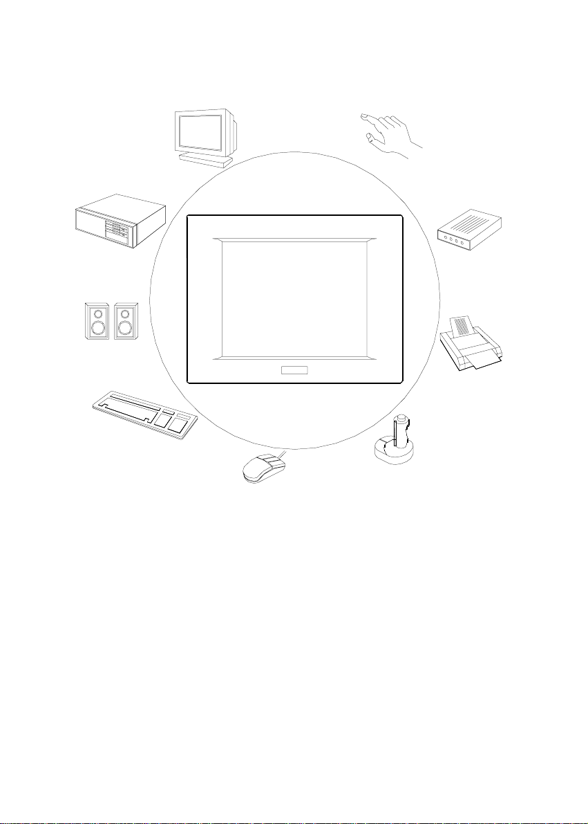
CRT Monitor
Touchscreen
Network
Speakers
Keyboard
Fax
modem
Printer
Joystick
Mouse
Figure 1-1:The panel PC in perspective
Chapter 1 General Information
3
Page 20

1.2 How to Use This Manual
This manual contains all the information you need to set up and use the
panel PC. In addition to this manual, you may also want to consult the
manuals for your operating system, software applications and peripherals.
Whether you are a new or an experienced user, you will benefit more from
this manual if you are familiar with its organization. This manual is
divided into ten chapters, plus five appendices.
Chapter 1 (this chapter) outlines the organization of this User's Manual,
provides a complete specification description of the PPC-150, and
summarizes its main features.
Chapter 2 provides step-by-step instructions to help you set up and begin
using the panel PC as quickly as possible.
Chapter 3 provides important information about the daily use of the panel
PC, including using the CD-ROM drive, floppy drive and enjoying the
panel PC's audio capabilities.
Chapter 4 provides detailed step-by-step instructions to help you install
the internal key components, including the CPU, hard disk drive, memory
module, and so on.
Chapter 5 provides a detailed description of jumper settings and connectors of the motherboard of the PPC-150.
Chapter 6 explains the PCI bus Ethernet setup.
Chapter 7 explains the PCI SVGA setup.
Chapter 8 explains the audio setup.
Chapter 9 explains the A ward BIOS setup.
Chapter 10 explains how to configure and use the optional touchscreen.
Appendix A details the LCD specifications used in the PPC-150.
Appendix B explains how to program the watchdog timer.
Appendix C includes various exploded diagrams of the PPC-150. These
diagrams will help system integrators disassemble the panel PC.
Appendix D includes all pin assignments on the connectors.
4
PPC-150 User's Manual
Page 21

Appendix E helps users install the panel PC, which is mountable in a
variety of ways.
If you are a commercial user and the panel PC unit you bought is a
complete set with CPU, hard disk drive, SDRAM, CD-ROM drive, floppy
disk drive and PCMCIA expansion slots included, you may only need to
read Chapters 1 through 3 regarding hardware operation. For additional
drivers and BIOS setup information, you should read Chapters 6 through
9. If you want to upgrade your system, you may follow the instructions in
Chapters 4 and 5. Chapter 10 is for users who want information about the
optional touchscreen. If you are a system integrator who wants to integrate
the panel PC into your system, you can refer to Appendices A through E
for information such as pin assignments and how to fully disassemble the
panel PC.
A suggested guideline for reading this manual is shown below:
Systems Integrators:
Appendices A - E
Systems Upgrades:
Chapter 4-5
Commercial Users:
Chapters 1-3, 6-9,
10 (optional)
Figure 1-2: How to read the PPC-150 manual
Chapter 1 General Information
5
Page 22

1.3 Specifications
General
• Dimensions (W x H x D): 420 x 323 x 106 mm (16.54" x 12.72" x
4.17")
• Weight: 6.5 kg (14.4 lbs)
• Power supply:
80 watts
Input voltage: 90 V
Output voltage: +5 V @ 12 A, +12 V @ 1 A
• Cooling fan dimensions (L x W x H):
40 x 40 x 10 mm (1.6" x 1.6" x 0.4")
• Disk drive housing: Space for one 2.5" HDD, one 12.7 mm compact
CD-ROM drive, and one slim type 3.5" FDD
• Front panel: IP65 protection (not for the model with SAW touch-
screen)
Standard PC functions
• CPU: Intel Pentium® 75 ~ 233 MHz with MMX, P55C/P54C,
AMD K5, K6, K6-2, Cyrix M1, M2
• BIOS: Award 256KB Flash BIOS, supports Plug & Play , APM
• Chipset: SiS 5582
• 2nd level cache: On-board 512 KB Pipeline Burst SRAM
• RAM: One 168-pin DIMM socket accepts 16 ~ 128 MB SDRAM (3.3 V)
• PCI bus master IDE interface: Supports two connectors. Each
connector has one channel and supports two IDE devices. Each channel
supports PIO modes 0 ~ 4, DMA mode 0 ~ 2, and Ultra DMA 33
simultaneously . The secondary connector is designated for the
CD-ROM drive. BIOS supports IDE CD-ROM boot-up.
• Floppy disk drive: Supports up to two FDDs (720K/1.44MB). One
built-in FDD included inside FDD housing
• Parallel port: One parallel port, supports SPP/EPP/ECP parallel mode.
BIOS configurable to LPT1, LPT2, LPT3 or disabled
/ 3 A ~ 260V
AC
/ 1.5A @ 47 ~ 63 Hz
AC
6
PPC-150 User's Manual
Page 23

• Serial ports: Four serial ports with three RS-232 ports (COM1, 3, and
4), one RS-232/422/485 port (COM2). All ports are compatible with
16C550 UARTs.
• Universal serial bus (USB) port: Supports up to two USB ports
• PCI/ISA bus expansion slot: Accepts either one ISA card or one PCI
bus card
• Watchdog timer: 63-level, interval 1 ~ 63 seconds.
Automatically generates system reset or IRQ11 when the system stops
due to a program error or EMI. Jumperless selection and software
enabled/disabled
• Battery: 3.0 V @ 190 mA lithium battery
PCI SVGA/flat panel interface
• Chipset: C&T 65555
• Display memory: 2 MB on-board memory , supports up to 4 MB
• Display type: Simultaneously supports CR T and flat panel displays
(EL, LCD and gas plasma)
• Display resolution: Supports non-interlaced CR T and LCD displays up
to 1024 x 768 @ 65536 colors. If display memory is expanded to 4
MB, supports CRT and LCD displays up to 1280 x 1024 with true-color
resolution.
Audio function
• Chipset: ESS 1869
• Audio controller: 16-bit codec, Full-Duplex stereo single-chip audio
solution
• Stereo sound: 100% DOS GAME compatible (Sound Blaster or Sound
Blaster Pro)
• Audio interface: Microphone in, line in, line out and game port.
Chapter 1 General Information
7
Page 24

PCI bus Ethernet interface
• Chipset: Realtek R TL 8139A PCI local bus Ethernet controller
• Ethernet interface: Full compliance with IEEE 802.3u 100Base-T and
10 Base-T specifications. Includes software drivers and boot ROM
• 100/10Base-T auto-sensing capability
Touchscreen (optional)
• Type: Analog resistive / SAW(Surface Acoustic Wave)
• Resolution: Continuous / 4096 x 4096
• Light transmission: 75% (surface meets ASTM-D-1044 standard,
Taber abrasion test) / 91%
• Controller: RS-232 interface (uses COM4)
• Power consumption: +5 V @ 200 mA / +5V @ 150mA
• Software driver: Supports DOS, Windows 3.1, Windows 95/98,
Windows NT 4.0 and OS/2
• Durability: 30 million touches lifetime / 50 million touches lifetime
Note: The panel PC with the optionally installed touchscreen
will share COM4. Once the touchscreen is installed,
COM4 cannot be used for other purposes.
8
PPC-150 User's Manual
Page 25

Optional modules
• CPU: Intel Pentium® 75 ~ 233 MHz with MMX, P55C/P54C,
AMD K5, K6, K6-2 Cyrix M1, M2
• Memory: 16/32/64/128 MB SDRAM
• HDD: 2.5" HDD
• Touchscreen: Analog resistive or Surface Acoustic Wave
• CD-ROM drive: Compact 24X CD-ROM or above
• PCMCIA interface: Complies with 1995 PCMCIA card standard.
Supports two PCMCIA card/CardBus slots. T wo sockets support both a
16-bit PCMCIA card and a 32-bit CardBus simultaneously. Hot
insertion and removal
Note 1: The PCMCIA driver is an option which does not come
with the PCMCIA interface. For more inf ormation,
contact your local dealer or our sales representative.
Note 2: Microsoft's new operating system, Windo ws 98,
supports the TI1250 PCMCIA function.
Note 3: The SAW models do not support PCMCIA cards due to
the compact dimensions of the system.
Environment
• Temperature:
0° ~ 45° C (32° ~ 122° F)
• Relative humidity: 10 ~ 95% @ 40
• Shock: 10G peak acceleration (11 msec duration)
• Power MTBF: 50,000 hrs
• Certification: Meets CE, FCC Class B
° C (non-condensing)
Chapter 1 General Information
9
Page 26
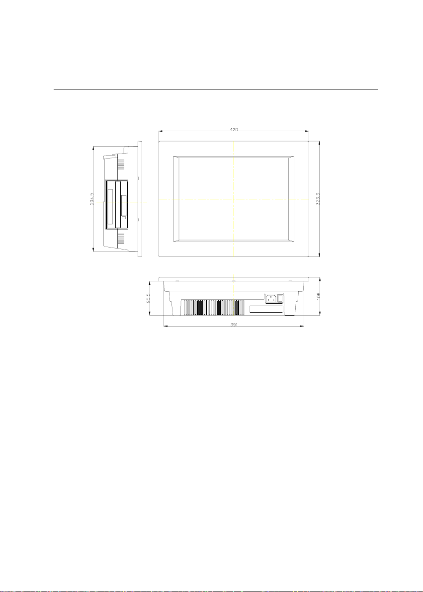
1.4 Dimensions
Figure1-3: Dimensions of the PPC-150
10
PPC-150 User's Manual
Page 27

CHAPTER
System Setup
A Quick Tour of the Panel PC
Preparing for First-time Usage
Running the Setup Program
Installing the System Software
Installing the Drivers
2
Page 28
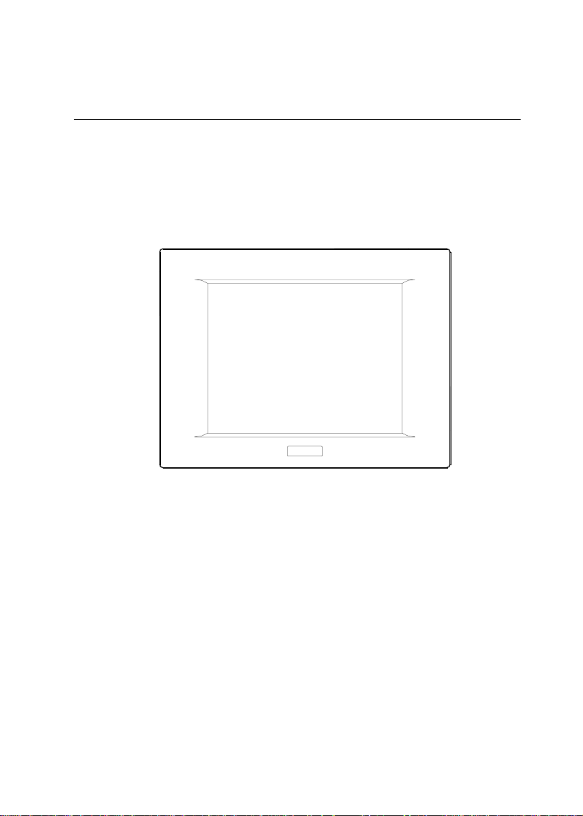
2.1 A Quick Tour of the Panel PC
Before you start to set up the panel PC, take a moment to become familiar
with the locations and purposes of the controls, drives, connectors and
ports, which are illustrated in the figures below.
When you place the panel PC upright on the desktop, its front panel
appears as shown in Figure 2-1.
Figure 2-1: Front view of the panel PC
12
PPC-150 User's Manual
Page 29
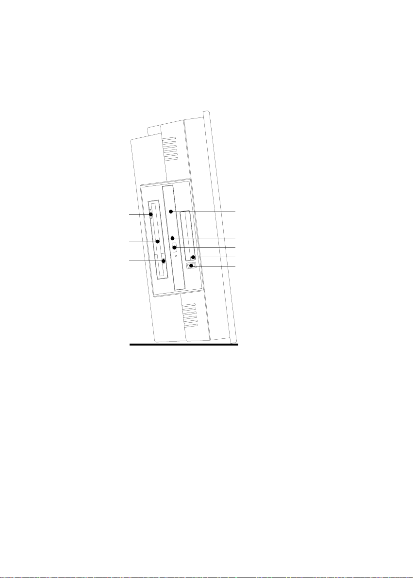
When you look at the left side of the panel PC, you will see the floppy
disk drive, CD-ROM drive and PCMCIA expansion sockets, as shown in
Fig. 2-2.
FDD eject button
FDD slot
FDD activity light
Compact CD-ROM drive
CD-ROM drive activity light
CD-ROM eject button
PCMCIA socket
PCMCIA eject button
Figure 2-2: Left side view of the panel PC
Chapter 2 System Setup
13
Page 30
When you turn the panel PC around and look at its rear cover, you will
find the PCI/ISA expansion slot located on the left side. This slot is
covered by a side panel cover. The sunken I/O section is at the bottom of
the panel PC, as shown in Fig. 2-3. (The I/O section includes various I/O
ports, including serial ports, parallel port, the Ethernet port, USB ports,
the microphone jack, and so on.)
PCI/ISA expansion
slot cover
PS/2 mouse and
keyboard connector
USB ports
Ethernet jack
Contrast adjust knob
Brightness adjust knob
Line out jack
Line in jack
Microphone in jack
Parallel port
Serial ports
VGA port
Game port
Figure 2-3: Rear view of the panel PC
14
PPC-150 User's Manual
Page 31

Figure 2-4 shows the I/O section and power switch of the panel PC.
Main power switch
AC inlet
Figure 2-4: Tilted rear view of the panel PC
2.2 Preparing For First-time Use
Before you start to set up the panel PC system, you should have at least
the following items ready:
Power cord (in the accessory box)
Y-shaped connector (in the accessory box)
AT keyboard
PS/2 or serial mouse (for system software installation i.e. Microsoft
Windows, NT, etc.)
Chapter 2 System Setup
15
Page 32

2.3 Installation Procedures
2.3.1 Connecting the power cord
The panel PC can only be powered by an AC electrical outlet (90 ~ 260
volts, 47 ~ 63 Hz). Be sure to always handle the power cords by holding
the plug ends only.
Follow these procedures in order:
1. Connect the female end of the power cord to the AC inlet of the panel
PC. (See Fig. 2-5.)
2. Connect the 3-pin male plug of the power cord to an electrical outlet.
AC inlet
Electrical outlet
Power cord
16
PPC-150 User's Manual
Figure 2-5: Connecting the power cord
Page 33

2.3.2 Connecting the keyboard and mouse
1. Connect the Y-shaped adapter to the PS/2 mouse and keyboard port on
the I/O section of the panel PC. (See Fig. 2-6.)
2. Connect the PS/2 mouse and keyboard to the Y-shaped adapter. (See
Fig. 2-6.)
If you use a serial mouse and your panel PC has a touchscreen, you can
connect the mouse to any COM port except COM4.
Y-shaped adapter
PS/2 mouse and
keyboard port
PS/2 mouse
Keyboard
Figure 2-6: Connecting the keyboard and mouse
2.3.3 Switching on the power
Switch on the power switch on the rear cover. (See Fig. 2-4.)
Chapter 2 System Setup
17
Page 34

2.4 Running the BIOS Setup Program
Your panel PC is likely to have been properly set up and configured by
your dealer prior to delivery. You may still find it necessary to use the
panel PC's BIOS (Basic Input-Output System) setup program to change
system configuration information, such as the current date and time or
your type of hard drive. The setup program is stored in read-only memory
(ROM). It can be accessed either when you turn on or reset the panel PC,
by pressing the "Del" key on your keyboard immediately after powering
on the computer.
The settings you specify with the setup program are recorded in a special
area of memory called CMOS RAM. This memory is backed up by a
battery so that it will not be erased when you turn off or reset the system.
Whenever you turn on the power, the system reads the settings stored in
CMOS RAM and compares them to the equipment check conducted
during the power on self-test (POST). If an error occurs, an error message
will be displayed on screen, and you will be prompted to run the setup
program.
If you want to change the setup of BIOS, refer to Chapter 9 for more
detailed information.
2.5 Installing System Software
Recent releases of operating systems from major vendors include setup
programs which load automatically and guide you through hard disk
preparation and operating system installation. The guidelines below will
help you determine the steps necessary to install your operating system on
the panel PC hard drive.
Note: Some distributors and system integrators may hav e
already pre-installed system software prior to shipment
of your panel PC.
18
PPC-150 User's Manual
Page 35

If required, insert your operating system's installation or setup diskette
into the diskette drive until the release button pops out. (See Fig. 3-1.)
The BIOS of the panel PC supports system boot-up directly from the
CD-ROM drive. You may also insert your system installation CD-ROM
into the CD-ROM drive. (See Fig. 3-2.) Refer to Chapter 9 - BIOS Setup
if you wish to change the BIOS settings.
Power on your panel PC or reset the system by pressing the
"Ctrl"+"Alt"+"Del" keys simultaneously. The panel PC will automatically
load the operating system from the diskette or CD-ROM.
If you are presented with the opening screen of a setup or installation
program, follow the instructions on screen. The setup program will guide
you through preparation of your hard drive, and installation of the
operating system.
If you are presented with an operating system command prompt, such as
A:\>, then you must partition and format your hard drive, and manually
copy the operating system files to it. Refer to your operating system user's
manual for instructions on partitioning and formatting a hard drive.
2.6 Installing the Drivers
After installing your system software, you will be able to set up the
Ethernet, SVGA, audio, and touchscreen functions. All the drivers except
the CD-ROM drive driver are stored in a CD-ROM disc entitled "Drivers
and Utilities". The CD-ROM drive driver is stored in a floppy disk. Both
the CD-ROM and the floppy disk can be found in your accessory box.
To set up the CD-ROM function, insert the floppy disk with the CD-ROM
drive driver into the floppy disk drive and type "install" after the following
prompt is displayed on screen:
A: > INSTALL
Press "Enter", and the installation process will be completed in a few
seconds.
The standard procedures for installing the Ethernet, SVGA, audio, and
touchscreen drivers are described in Chapters 6, 7, 8 and 10 respectively.
Chapter 2 System Setup
19
Page 36

For your reference, the directory of drivers on the "Drivers and Utilities"
CD-ROM is:
Audio (drivers)D:
Document (manuals)
Elotouch (drivers)
LAN (Ethernet drivers)
Microtouch (drivers)
Utility
VGA (drivers)
The utility directory includes multimedia programs. Refer to the
README.TXT file inside the BIOS folder for more detailed information.
The various drivers and utilities in the CD-ROM disc have their own text
files which help users install the drivers and understand their functions.
These files are a very useful supplement to the information in this manual.
Note: The drivers and utilities used for the PPC-150 panel
PCs are subject to change without notice. If in doubt,
check Advantech's web site or contact our application
engineers for the latest information regarding drivers
and utlities.
20
PPC-150 User's Manual
Page 37

3
CHAPTER
Using the Panel PC
Floppy Drive
CD-ROM Drive
PCMCIA Sockets
PS/2 Mouse and Keyboard
Audio Interface
PCI/ISA Bus Expansion
Parallel Port
Serial COM Ports
VGA Port
Game Port
USB Ports
Audio Interface
Ethernet
Adjusting the LCD Contrast and
Brightness
Touchscreen (Optional)
Page 38

3.1 Introduction
This chapter describes basic features and procedures for using the panel
PC. Topics covered include the floppy drive, CD-ROM drive, I/O ports,
touchscreen, and so on.
3.2 Floppy Drive
To insert a diskette, hold it with your left hand, between your thumb and
your other fingers, and push it toward the drive. (See Fig. 3-1.) Slide the
disk until it clicks into place. Note that new diskettes must be formatted by
your operating system before you can use them for data storage. See your
operating system manual for details.
To eject a diskette, first ensure that the drive activity light is off, and then
press the eject button on the drive. When the diskette pops out of the
drive, remove it and store it properly.
Floppy disk drive
Floppy disk
Figure 3-1: Inserting and ejecting a floppy diskette
22
PPC-150 User's Manual
Page 39

3.3 CD-ROM Drive
To insert a CD-ROM disc, press the eject button of the CD-ROM drive.
The yellow activity light will flash and the front panel will come out a
short distance. Using your fingertips, hold the top and bottom of the front
panel and pull it outward to the very end. (See Fig 3-2.) Align the center
hole of the CD-ROM disc with the center circle of the CD-ROM holding
plate. Press the transparent ring around the center hole of the CD-ROM
until you hear a click. Push the front panel of the CD-ROM drive back to
its original place.
To eject a CD-ROM disc, first ensure that the drive activity light is off.
Then press the eject button on the drive. When the disc pops out of the
drive, remove it and store it properly.
CD-ROM
holding plate
CD-ROM
Figure 3-2: Inserting and ejecting a CD-ROM disc
Chapter 3
Using the Panel PC
23
Page 40

3.4 PCMCIA
PCMCIA cards are inserted and ejected in much the same way as
diskettes.
To insert a PCMCIA card, align the card with the socket and slide the card
into the socket until it locks into place. Note that some PCMCIA memory
cards must be prepared by your operating system before you can use them
for data storage. See your PCMCIA card manual for details.
To eject a PCMCIA card, first ensure that the panel PC is not accessing
the memory card or device. Then press the appropriate eject button on the
socket. When the card pops out of the socket, remove it and store it
properly.
PCMCIA socket
PCMCIA card
Eject button
24
PPC-150 User's Manual
Figure 3-3: Inserting and ejecting a PCMCIA card
Page 41

USB
keyboard
PS/2
mouse
PrinterNetwork
Figure 3-4: Using the I/O interface (upper level ports excluding COM ports)
Chapter 3
Using the Panel PC
25
Page 42

CD-ROM
player
MicrophoneHeadphones
Joystick
CRT
monitor
mouse
Figure 3-5: Using the I/O interface (lower level ports and COM ports)
26
PPC-150 User's Manual
Serial
Page 43

3.5 PS/2 Mouse and Keyboard
If you wish to use a full-size desktop keyboard and PS/2 mouse with your
panel PC, follow these instructions:
1. Be sure the panel PC is turned off.
2. Connect the Y-shaped adapter to the PS/2 mouse and keyboard port on
the rear bottom side of the rear cover. (See Fig. 3-4 and Fig. 2-6.)
3. Attach the keyboard to the 5-pin port of the Y-shaped adapter.
4. Attach the PS/2 mouse to the 6-pin female PS/2 port of the Y-shaped
adapter.
5. Turn on the panel PC.
3.6 PCI/ISA Bus Expansion
The panel PC supports PCI and ISA bus expansion cards. To integrate a
new PCI or ISA bus card into your system, follow these instructions:
1. Turn off the panel PC.
2. Unscrew the two screws on the top of the PCI/ISA bus expansion slot
cover, and remove this cover.
3. Remove the metal plate by unscrewing the single attaching screw.
4. Insert the PCI or ISA bus card into the PCI/ISA slot of the riser card.
(See Fig. 3-6 overleaf.)
5. Run the setup program within your operating system to configure your
system.
Chapter 3
Using the Panel PC
27
Page 44

PCI/ISA
expansion
slot cover
PCI/ISA bus
card
Metal plate
Figure 3-6: PCI/ISA bus expansion
28
PPC-150 User's Manual
Page 45

3.7 Parallel Port
The panel PC supports the latest EPP and ECP parallel port protocols for
improved performance and versatility with compatible printers or other
devices.
To connect the panel PC to a printer or other devices:
1. Be sure both the panel PC and the printer/devices are turned off.
2. Connect the 25-pin male connector of the printer cable to the 25-pin
female port on the panel PC labelled "parallel port".
3. If necessary, attach the other end of your printer cable to your printer,
and fasten any retaining screws. A typical parallel printer connection is
illustrated in Fig. 3-4.
4. Turn on the printer and any other peripheral devices you may have
connected to the panel PC, and then turn on the panel PC.
5. If necessary, run the panel PC's BIOS setup program to configure the
parallel port to respond as required by your printer and software
operating environment.
3.8 Serial COM Ports
There are four serial COM ports on the bottom of the rear cover. You can
easily attach a serial device to the panel PC, such as an external modem or
mouse. Follow these instructions:
1. Be sure the panel PC and any other peripherial devices you may have
connected to the panel PC are turned off.
2. Attach the interface cable of the serial device to the panel PC's serial
port. (See Fig. 3-5.) If necessary, attach the other end of the interface
cable to your serial device. Fasten any retaining screws.
3. Turn on any other peripheral devices you may have connected to the
panel PC, and then turn on the panel PC.
4. Refer to the manual(s) which accompanied your serial device(s) for
instructions on configuring your operating environment to recognize
the device(s).
5. Run the BIOS setup program and configure the jumper settings to
change the mode of the COM ports. (See Section 5.3.)
Chapter 3
Using the Panel PC
29
Page 46

3.9 VGA Port
An external VGA-compatible device may be connected to the system
through the 15-pin external port located on the rear of the system unit. The
panel PC simultaneously supports an external CRT monitor in addition to
its own LCD display.
1. Be sure the panel PC is turned off.
2. Connect the external monitor to the system. (See Fig. 3-5.)
3. Turn on the panel PC and the external monitor.
3.10 Game Port
An external game device may be connected to the system through the
15-pin external port located on the rear of the system unit.
1. Be sure the panel PC is turned off.
2. Connect the external joystick or game device to the system. (See Fig.
3-5.)
3. Turn on the panel PC and the external joystick or game device (if
applicable).
4. Install the driver before you use the joystick or game device.
3.11 USB Ports
An external USB device may be connected to the system through the 4-pin
USB ports located on the rear side of the system unit.
1. Connect the external device to the system. (See Fig. 3-4.)
2. The USB ports support hot plug-in connection. You should install the
device driver before you use the device.
30
PPC-150 User's Manual
Page 47

3.12 Audio Interface
The audio interface includes three jacks: microphone in, line out and line
in. (See Fig. 3-5.) Their functions are:
Microphone in: Use an external microphone to record voice and sound.
Line out: Output audio to external devices such as speakers or earphones.
Line in: Input audio from an external CD player or radio.
1. Connect the audio device to the system. (See Fig. 3-5.)
2. Install the driver before you use the device.
3.13 Ethernet
External devices on your network may be connected to the system through
the external ethernet port located on the rear side of the system unit.
1. Be sure the panel PC is turned off.
2. Connect the external device(s) to the panel PC. (See Fig. 3-4.)
3. Turn on the panel PC and the external device(s).
4. Under DOS, run the RSET8139 program to check the hardware
network status before installing the Ethernet driver.
5. Run the Ethernet driver to connect up to the network.
3.14 Adjusting the LCD Contrast and Brightness
The contrast control knob does not function because the PPC-150 includes
the TFT LCD display. Only panel PCs with DSTN LCD displays have this
function.
The brightness control knob allows you to adjust the brightness of the
LCD display panel.
Chapter 3
Using the Panel PC
31
Page 48

3.15Touchscreen (Optional)
The touchscreen is connected to COM4. Its function is similar to that of a
mouse. The only difference is that you put your fingertip on the screen to
move the cursor.
You will need to install the touchscreen driver before it will work. The
touchscreen drivers for various operating systems are stored on the
CD-ROM disc inside the accessory box. The touchscreen manual can also
be found on this disc. Read Chapter 10 of this manual carefully before you
install the driver.
32
PPC-150 User's Manual
Page 49

4
CHAPTER
Hardware Installation
and Upgrading
Overview of Hardware Installation
and Upgrading
Disassembling the Panel PC
Installing the 2.5" Hard Disk Drive
(HDD)
Installing the Central Processing Unit
(CPU)
Installing the SDRAM Memory
Module
Installing the Floppy Disk Drive
(FDD)
Installing the CD-ROM Drive
Page 50

4.1 Overview of Hardware Installation and
Upgrading
The panel PC consists of a PC-based computer that is housed in a plastic
rear panel and a shielding case. Your HDD, SDRAM, power supply, CPU,
and so on are all readily accessible by removing the rear panel and
shielding case. Any maintenance or hardware upgrades can be easily
completed after removing the rear panel and shielding case.
If you are a systems integrator and need to know how to completely
disassemble the panel PC, you can find more useful information in
Appendix C.
Warning! Do not remove the rear cover until you have verified
that no power is flowing within the panel PC. Power
must be switched off and the power cord must be
unplugged. Every time you service the panel PC, you
should be aware of this.
34
PPC-150 User's Manual
Page 51

4.2 Disassembling the Panel PC
The following are standard procedures for disassembling the panel PC
before you upgrade your system. All procedures are illustrated in Fig. 4-1.
1. Unscrew the seven screws that secure the rear cover, then remove the
cover.
2. Unscrew the two screws of the PCI/ISA expansion PCB, and remove it.
3. Unscrew the four screws that secure the CPU cover.
4. Remove the floppy drive, HDD, and CD-ROM cables; then remove
the side panel.
5. Unscrew the ten screws of the shielding case, and remove it.
6. Detach the ventilation fan power cable.
Chapter 4 Hardware Installation and Upgrading
35
Page 52

Rear panel
CPU cover
PCI/ISA
expansion PCB
Side panel
Figure 4-1: Disassembling the rear panel of the panel PC
36
PPC-150 User's Manual
Page 53

4.3 Installing the 2.5" Hard Disk Drive (HDD)
You can attach one enhanced Integrated Device Electronics (IDE) hard
disk drive to the panel PC's internal controller which uses a PCI local-bus
interface. The advanced IDE controller supports faster data transfer and
allows the IDE hard drive to exceed 528 MB. The following are instructions
for installation:
1. Detach and remove the rear cover and side panel.
2. There is a metal plate holding the HDD on the upper right-hand side of
the shielding case. (See Fig. 4-2.) Remove the two screws on the metal
plate.
3. Push the metal plate to the right and remove it from the two lugs of
shielding case.
4. Place the HDD on the metal plate, and tighten the four screws from the
bottom of the metal plate.
5. The HDD cable (1 x 44-pin to 1 x 44-pin) is next to the metal plate.
Connect the HDD cable to the HDD. The another end of the HDD
cable is connected to the PC board (J7). Make sure that the red/blue
wire corresponds to Pin 1 on the connector, which is labeled on the
board. Plug the other end of the cable into the IDE hard drive, with Pin
1 on the cable corresponding to Pin 1 on the hard drive.
2.5" HDD
Figure 4-2: Installing the primary 2.5" HDD
Chapter 4 Hardware Installation and Upgrading
Metal plate
Lugs
37
Page 54

4.4 Installing the Central Processing Unit (CPU)
The panel PC's central processing unit (CPU) can be upgraded to improve
system performance. The panel PC provides one 321-pin ZIF (Zero
Insertion Force) socket (Socket 7) which is backward compatible with ZIF
Socket 5 processors. The CPU must come with an attached heatsink and
CPU fan to prevent overheating. The panel PC comes with one CPU fan
with a unique connector in the accessory box.
Warning! The CPU may be damaged if operated without a
heatsink and a fan.
Warning! Always disconnect the pow er cord from y our panel PC
when you are working on it. Do not mak e connections
while the power is on as sensitive electronic components
can be damaged by the sudden rush of power . Only
experienced electronics personnel should open the panel PC.
1. Detach and remove the rear cover, shielding case and side panel.
2. Detach the flat cables of the HDD, FDD and CD-ROM drives.
3. Unscrew the ten screws of the shielding case and remove the case.
4. Locate the ZIF socket and open it by first pulling the lever sideways
away from the socket, then upwards at an angle of 90 degrees.
5. Insert the CPU with the correct orientation. The notched corner of the
CPU (with the white dot) should point towards the end of the lever.
The end of the lever is the blank area where one hole is missing from
the corner of the square array of pin holes. An arrowhead printed on
the motherboard points to the end of the lever. (See Fig. 4-3 overleaf.)
6. Slide the CPU in gently. It should insert easily. If not, pull the lever up
a little more and make sure the pins of the CPU correspond with the
holes of the socket. DO NOT USE EXCESSIVE FORCE!
7. Press the lever down. The plate will slide forward.
8. Place the heatsink on top of the CPU and tighten it with the heatsink
clip (shown in Fig. 4-3).
9. Attach the CPU fan to the CPU heatsink with the four screws.
38
PPC-150 User's Manual
Page 55

10. Connect the power cable of the CPU fan to the 2-pin connector (J12).
11. After changing the CPU, you must set jumpers, including those for the
PCI bus clock (JP8), system/PCI clock (JP11), frequency ratio (JP14),
and voltage (JP13). (See Section 5.2.)
12. To remove the CPU, pull the lever out to the side a little and raise it as
far as it will go. Lift out the CPU chip.
NOTE! When you install a new CPU , be sure to adjust the
board jumper settings. Improper settings ma y damage
the CPU. (See Chapter 5 for jumper settings.)
CPU fan
Heat sink
clip
Heat sink
CPU
Figure 4-3: Installing the CPU
Chapter 4 Hardware Installation and Upgrading
Lever
Socket 7
39
Page 56

4.5 Installing the SDRAM Memory Module
You can install from 16 MB to 128 MB of SDRAM memory. The panel
PC system provides one 168-pin DIMM (Double Inline Memory Module)
socket and supports 3.3 V SDRAM with a minimum speed of 12 ns.
Note: The module can fit into the socket only one way. Pin 1 of
the DIMM module must line up with the small arrowhead
printed on the motherboard next to the DIMM socket.
The golden pins of the module must point down into the
DIMM socket.
1. Detach and remove the rear cover and CPU cover.
2. Push the two white eject levers on each side of the DIMM outward
until they are separated from the black vertical posts. (See Fig. 4-4.)
3. Insert the memory module into the socket at an angle of 90 degrees.
4. Push the two eject levers towards the vertical posts at each end of the
socket until the module is upright.
SDRAM
40
PPC-150 User's Manual
Figure 4-4: Installing the SDRAM
Page 57

4.6 Installing the Floppy Disk Drive (FDD)
Installation of a floppy disk drive is similar to that for a hard disk drive.
The metal plate for holding the FDD is on the left side of the shielding
case. The 26-pin yellow FPC cable is for connecting the FDD. Only 3.5"
floppy disk drives (720 KB and 1.44 MB) can be attached to the metal
plate.
1. Detach and remove the rear cover and side panel.
2. There is a metal plate for holding the FDD on the right side of the
shielding case. (See Fig. 4-5.) Unscrew the two screws on the upper
side of the metal plate.
3. Push the metal plate to the right and remove it from the two lugs of the
shielding case.
4. Place the FDD on the metal plate. Tighten the four smaller screws
located on each side of the metal plate.
5. Connect the yellow FDD cable (26-pin to 26-pin) which is next to the
metal plate of the FDD. The other end of the FDD cable is connected
to connector J8 on the PC board.
6. Attach the two screws of the metal plate to the original hole.
3.5" floppy drive
Figure 4-5: Installing the FDD
Chapter 4 Hardware Installation and Upgrading
Metal plate
41
Page 58

4.7 Installing the CD-ROM Drive
The compact CD-ROM drive used in the panel PC is not the common
5.25" CD-ROM drive seen in computer shops. It is the kind widely used
in notebook computers. Install the CD-ROM drive as follows:
1. Detach and remove the rear cover, side panel and CPU cover.
2. Fasten the retaining clip on the CD-ROM drive with the two screws.
3. Slide the slim CD-ROM drive into the CD-ROM slot. (See Fig. 4-6.)
4. Attach the two screws on the side panel of the CD-ROM slot.
5. Connect the 40-pin CD-ROM cable (which has a small converting
PCB at its end) to the CD-ROM drive. The other end of the cable is
connected to CD-ROM connector J9 on the motherboard.
6. Rotate the retaining spring, to secure the CD-ROM connector (with
converting PCB) in place.
CD-ROM
connector
42
PPC-150 User's Manual
Retaining
spring
Compact
CD-ROM drive
Figure 4-6: Installing the CD-ROM drive
Page 59

5
CHAPTER
Jumper Settings and
Connectors
This chapter tells how to set up the panel
PC hardware, including instructions on
setting jumpers and connecting peripherals,
switches and indicators. Be sure to read
all the safety precautions before you begin
the installation procedures.
Jumpers and Connectors
CPU Installation and Upgrading
COM Port Interface
VGA Interface
Watchdog Timer Configuration
Page 60

5.1 Jumpers and Connectors
5.1.1 Setting jumpers
You can configure your panel PC to match the needs of your application
by setting jumpers. A jumper is the simplest kind of electrical switch. It
consists of two metal pins and a small metal clip (often protected by a
plastic cover) that slides over the pins to connect them. To close a
jumper, you connect the pins with the clip. To open a jumper you
remove the clip. Sometimes a jumper will have three pins, labeled 1, 2,
and 3. In this case, you would connect either pins 1 and 2 or pins 2 and 3.
3
2
1
OpenOpen
Open
OpenOpen
ClosedClosed
Closed
ClosedClosed
Closed 2 - 3Closed 2 - 3
Closed 2 - 3
Closed 2 - 3Closed 2 - 3
The jumper settings are schematically depicted in this manual as follows:
1
OpenOpen
Open
OpenOpen
ClosedClosed
Closed
ClosedClosed
Closed 2 - 3Closed 2 - 3
Closed 2 - 3
Closed 2 - 3Closed 2 - 3
A pair of needle-nose pliers may be helpful when working with jumpers.
If you have any doubts about the best hardware configuration for your
application, contact your local distributor or sales representative before
you make any changes.
44
PPC-150 User's Manual
Page 61

5.1.2 Jumpers
The motherboard of the panel PC has a number of jumpers that allow you
to configure your system to suit your applications. The table below lists
the function of each of the boards jumpers.
Table 5-1: Jumpers and their functions
Label Function
JP1 COM3 RI pin setting (Reserved)
JP2 COM4 RI pin setting (Reserved)
JP3 COM2 RS-232/422/485 setting
JP4 COM2 RS-232/422/485 setting
JP5 COM2 RS-232/422/485 setting
JP6 Panel VCC setting
JP7 ENVEE pin setting
JP8 PCI bus clock setting
JP9 Panel type select
JP10 Cyrix linear mode enable
JP11 System/PCI clock setting
JP12 CMOS clear for external RTC
JP13 CPU V
JP14 CPU frequency ratio setting
JP15 Watchdog timer action
JP16 Reset
JP17 CMOS clear for 5582 internal RTC (Reserved)
voltage setting
CORE
Chapter 5 Jumper Settings and Connectors
45
Page 62

5.1.3 Locating jumpers
JP14: CPU frequency ratio setting JP11: System/PCI clock setting
JP13: CPU V
voltage setting
CORE
JP9: Panel type select
JP17: CMOS
clear for
internal RTC
JP15:
Watchdog
timer action
JP16: Reset
JP12: CMOS
clear for
external RTC
JP4: COM2
RS-232/422/485
setting
JP3: COM2
RS-232/422/485
setting
JP1: COM3 RI
pin setting
(Reserved)
Figure 5-1: Locating jumpers on the PPC-150 motherboard
JP6: Panel V
setting
JP7: ENVEE
pin setting
JP8: PCI bus
clock setting
JP10: Cyrix
linear mode
enable
JP5: COM2
RS-232/422/485
setting
JP2: COM4 RI
pin setting
(Reserved)
cc
46
PPC-150 User's Manual
Page 63

5.1.4 Connectors
On-board connectors link the panel PC to external devices such as hard
disk drives or floppy drives. The table below lists the function of each of
the boards connectors.
Table 5-2: Panel PC connectors
Label Function
J1 IR connector (Reserved)
J2 Flat panel display connector
J3 Flat panel display connector
J4 Internal COM4 connector
J5 Touchscreen power connector
J6 Sandisk SSD connector
J7 EIDE hard disk driver connector
J8 Floppy drive connector
J9 CD-ROM connector
J10 CPU fan power connector
J11 PCI/ISA bus expansion connector
J12 Fan power connector
J13 AT power connector
J15 Internal speaker connector (Reserved)
J16 Inverter power connector
Chapter 5 Jumper Settings and Connectors
47
Page 64

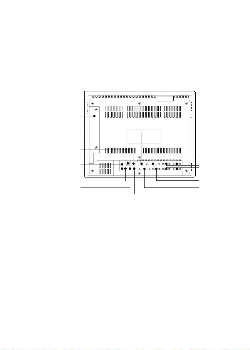
5.1.5 Locating connectors
J11: PCI/ISA
bus expansion
connector
J12: Fan power
connector
J13: AT power
connector
J16: Inverter
power
connector
J15: Internal
speaker
connector
(Reserved)
J10: CPU fan power
connector
J7: EIDE hard disk
drive connector
J6: Sandisk SSD
connector
J3: Flat panel
display connector
J5: Touchscreen
power connector
J4: Internal COM4
connector
J2: Flat panel
display connector
J9: CD-ROM
connector
J8: Floppy drive
connector
J1: IR connector
(Reserved)
Figure 5-2: Locating connectors on the PPC-150 motherboard
48
PPC-150 User's Manual
Page 65

5.2 CPU Installation and Upgrading
You can upgrade to a higher power Pentium®, AMD or Cyrix processor at
any time. Simply remove the old CPU, install the new one, and set the
jumpers for the new CPU type and speed.
5.2.1 System clock setting (JP11, JP8)
JP11 and JP8 are used to set the CPU and PCI bus speeds respectively, to
optimize the system's performance. The system chipset will sense the JP8
setting to get the bus frequency, then adjust its internal timing. JP11 is
used to set the CPU and PCI clock. Refer to the CPU speed reference
table for instructions on adjusting the internal clocks according to the base
CPU speed.
Chapter 5 Jumper Settings and Connectors
49
Page 66

Table 5-3: System/PCI clock setting (JP11)
PCI clock CPU clock
25 MHz 50 MHz
1
30 MHz 60 MHz
1
33 MHz 66 MHz
1
28 MHz 55 MHz
1
38 MHz 75 MHz
1
42 MHz 83 MHz
(Reserved)
50
PPC-150 User's Manual
1
Page 67

Table 5-4: PCI bus clock setting (JP8)
PCI clock
* CPUCLK/2
1
32MHz
1
* default setting
5.2.2 CPU core voltage setting (JP13)
JP13 must be set to match the CPU type. The following chart shows the
proper jumper settings for their respective V
CPU is fixed at 3.3 V.)
CC (CORE)
. (The V
CC (I/O)
for the
Chapter 5 Jumper Settings and Connectors
51
Page 68

Table 5-5: CPU voltage setting (JP13)
VCC
(CORE)
VCC
(CORE)
VCC
(CORE)
VCC
(CORE)
1.30 V 1.35 V 1.40 V 1.45 V
10
8
6
4
2
9
10
7
8
5
6
3
4
1
2
10
9
8
7
6
5
4
3
2
1
9
10
7
8
5
6
3
4
1
2
1.50 V 1.55 V 1.60 V 1.65 V
10
8
6
4
2
9
10
7
8
5
6
3
4
1
2
9
10
7
8
5
6
3
4
1
2
9
10
7
8
5
6
3
4
1
2
1.70 V 1.75 V 1.80 V 1.85 V
10
8
6
4
2
9
10
7
8
5
6
3
4
1
2
9
10
7
8
5
6
3
4
1
2
9
10
7
8
5
6
3
4
1
2
9
7
5
3
1
9
7
5
3
1
9
7
5
3
1
1.90 V 1.95 V 2.00 V 2.05 V
10
8
6
4
2
52
PPC-150 User's Manual
9
10
7
8
5
6
3
4
1
2
9
10
7
8
5
6
3
4
1
2
9
10
7
8
5
6
3
4
1
2
9
7
5
3
1
Page 69

VCC
(CORE)
VCC
(CORE)
VCC
(CORE)
VCC
(CORE)
NONE 2.10 V 2.20 V 2.30 V
10
9
10
8
6
4
2
7
8
5
6
3
4
1
2
10
9
7
8
5
6
3
4
1
2
9
10
7
8
5
6
3
4
1
2
2.40 V 2.50 V 2.60 V 2.70 V
10
9
10
8
6
4
2
7
8
5
6
3
4
1
2
9
10
7
8
5
6
3
4
1
2
10
9
8
7
5
6
3
4
1
2
2.80 V 2.90 V 3.00 V 3.10 V
10
9
10
8
6
4
2
7
8
5
6
3
4
1
2
10
9
8
7
5
6
3
4
1
2
9
10
7
8
5
6
3
4
1
2
9
7
5
3
1
9
7
5
3
1
9
7
5
3
1
3.20 V 3.30 V 3.40 V 3.50 V
10
9
10
7
8
6
4
2
8
5
6
3
4
1
2
10
9
8
7
6
5
4
3
2
1
Chapter 5 Jumper Settings and Connectors
10
9
8
7
6
5
4
3
2
1
9
7
5
3
1
53
Page 70

5.2.3 CPU frequency ratio setting (JP14)
Table 5-6: CPU frequency ratio (for Intel) (JP14)
P55C P54C
3.5x 1.5x
1
3
5
2x 2x
1
3
5
3x 3x
1
3
5
2.5x 2.5x
1
3
5
2
4
6
2
4
6
2
4
6
2
4
6
54
PPC-150 User's Manual
Page 71

Table 5-7: CPU frequency ratio (for AMD K6, K6-2) (JP14)
2x 2.5x
1
3
5
2
4
6
1
3
5
2
4
6
3x 3.5x
1
3
5
2
4
6
1
3
5
2
4
6
4x 4.5x
1
3
5
2
4
6
1
3
5
2
4
6
5x 5.5x
1
3
5
2
4
6
1
3
5
2
4
6
Chapter 5 Jumper Settings and Connectors
55
Page 72

5.2.4 CMOS clear for external RTC (JP12)
Warning: T o a void damaging the computer , alw ays turn off the
power supply before setting “Clear CMOS”. Set the
jumper back to “3.0 V Battery On” before turning on the
power supply.
Table 5-8: Clear CMOS/External RTC (JP12)
* normal operation
12
Clear CMOS
12
* default setting
5.2.5 Cyrix linear mode enable (JP10)
The panel PC supports Cyrix M1 CPU with its linear access mode on L2
cache. This mode is set through JP10.
Table 5-9: Cyrix linear mode enable (JP10)
* open = disable (normal operation)
closed = Cyrix linear mode
* default setting
2
1
2
1
56
PPC-150 User's Manual
Page 73

5.2.6 Reset system (JP16)
Table 5-10: Reset system (JP16)
* open = normal operation
2
1
closed = reset system
* default setting
2
1
Chapter 5 Jumper Settings and Connectors
57
Page 74

5.3 COM-port Interface
The panel PC provides four serial ports (COM1, 3, 4: RS-232; COM2: RS-
232/422/485) in one COM port connector.
5.3.1 COM2 RS-232/422/485 setting (JP3, JP4, JP5)
COM2 can be configured to operate in RS-232, RS-422, or RS-485 mode.
This is done via JP3, JP4 and JP5.
Table 5-11: COM2 RS-232/422/485 setting (JP3, JP4)
* RS-232 RS-422/485
26
JP4
15
26
JP3
15
JP4
JP3
26
15
26
15
* default setting
Table 5-12: COM2 RS-232/422/485 setting (JP5)
* RS-232 RS-422 RS-485
246 246 246
135 135 135
* default setting
The IRQ and the address ranges for COM1, 2, 3, and 4 are fixed.
However, if you wish to disable the port or change these parameters later
you can do this in the system BIOS setup. The table overleaf shows the
default settings for the panel PCs serial ports.
58
PPC-150 User's Manual
Page 75

COM1 and COM2 are one set. You can exchange the address range and
interrupt IRQ of COM1 for the address range and interrupt IRQ of COM2.
After exchanging, COM1's address range is 2F8 ~ 2FF and its request IRQ
is IRQ3: and COM2's address range is 3F8 ~ 3FF and its interrupt IRQ is
IRQ4.
COM3 and COM4 are another set. Their selectable function is the same as
the COM1/COM2 set.
Table 5-13: PPC-150 serial port default settings
Port Address Range Interrupt
COM1 3F8 ~ 3FF IRQ4
COM2 2F8 ~ 2FF IRQ3
COM3 3E8 ~ 3EF IRQ10
COM4 2E8 ~ 2EF IRQ5
5.3.2 COM3/COM4/RI pin setting (JP2, JP1) (Reserved)
Table 5-14: COM4/RI pin setting (JP2)
+5 V output +12 V output * RI output
65
43
21
65
43
21
65
43
21
* default setting
Table 5-15: COM3/RI pin setting (JP1)
+5 V output +12 V output * RI output
65
43
21
65
43
21
65
43
21
* default setting
Chapter 5 Jumper Settings and Connectors
59
Page 76

5.4 VGA Interface
1
The panel PC'ss PCI SVGA interface can drive conventional CRT displays
and is capable of driving a wide range of flat panel displays, including
electroluminescent (EL), gas plasma, passive LCD and active LCD
displays. The board has two connectors to support these displays
simultaneously; one for standard CRT VGA monitors and one for flat
panel displays.
CRT display port information can be found in Section 3.9 - VGA Port.
The pin assignments for the flat panel display connector, backlight
connector and other related connectors are described in the appendices.
5.4.1 LCD panel power setting (JP6)
The panel PC'ss PCI SVGA interface supports 5 V and 3.3 V LCD
displays. By changing the setting of JP6, you can select the panel video
signal level to be 5 V or 3.3 V.
Table 5-16: Panel VCC setting (JP6)
* 5 V 3.3 V
* default setting
123123
Configuration of the VGA interface is done exclusively via the software
utility. You do not have to set any jumpers. Refer to Chapter 8 for
software setup details.
60
PPC-150 User's Manual
Page 77

5.4.2 Panel type select (JP9)
Table 5-17: Panel type select (JP9)
Maximum Display Maximum Display
Resolution Type Resolution Type
1. 1024 x 768 DSTN color 2. 1280 x 1024 TFT color
7
5
3
1
8
6
4
2
7
5
3
1
8
6
4
2
3. 640 x 480 DSTN color 4. 800 x 600 DSTN color
7
5
3
1
8
6
4
2
7
5
3
1
8
6
4
2
5. 640 x 480 SHARP TFT color 6. 640 x 480 18-bit TFT color
7
5
3
1
8
6
4
2
7
5
3
1
8
6
4
2
7. 1024 x 768 TFT color 8. 800 x 600 TFT color
7
5
3
1
8
6
4
2
Chapter 5 Jumper Settings and Connectors
7
5
3
1
8
6
4
2
61
Page 78

Maximum Display Maximum Display
Resolution Type Resolution Type
9. 800 x 600 TFT color 10. 800 x 600 TFT color
(44 K BIOS only)
7
5
3
1
8
6
4
2
7
5
3
1
8
6
4
2
11. 800 x 600 DSTN color 12. 800 x 600 DSTN color
(44 K BIOS only)
7
5
3
1
8
6
4
2
7
5
3
1
8
6
4
2
13.1024 x 768 TFT color 14. 1280 x 1024 DSTN color
(44 K BIOS only) (44 K BIOS only)
7
5
3
1
8
6
4
2
7
5
3
1
8
6
4
2
15. 1024 x 600 TFT color 16.1024 x 600 TFT color
(48•K BIOS only)
62
PPC-150 User's Manual
7
5
3
1
8
6
4
2
7
5
3
1
8
6
4
2
Page 79

5.5 Watchdog Timer Configuration
1
An on-board watchdog timer reduces the chance of disruptions which
EMP (electromagnetic pulse) interference can cause. This is an invaluable
protective device for standalone or unmanned applications. Setup involves
one jumper and running the control software. (Refer to Appendix B.)
5.5.1 Watchdog activity selection (JP15)
When the watchdog timer activates (i.e. CPU processing has come to a
halt), it can reset the system or generate an interrupt on IRQ11. This can
be set via jumper JP15 as shown below:
Table 5-18: Watchdog activity selection (JP15)
* System reset IRQ11
3
2
1
* default setting
3
2
1
Chapter 5 Jumper Settings and Connectors
63
Page 80

64
PPC-150 User's Manual
Page 81

6
CHAPTER
PCI Bus Ethernet
Interface
This chapter provides information on
Ethernet configuration.
Introduction
Installation of Ethernet Driver
- Installation for MS-DOS &
WINDOWS 3.1
- Installation for WINDOWS 95/98
- Installation for WINDOWS NT
Further Information
Page 82

6.1 Introduction
The PPC-150 is equipped with a high performance 32-bit Ethernet chipset
which is fully compliant with IEEE 802.3 100 Mbps CSMA/CD stan-
dards. It is supported by major network operating systems. It is also both
100Base-T and 10Base-T compatible. The medium type can be config-
ured via the RSET8139.exe program included on the utility disk.
The Ethernet port provides a standard RJ-45 jack. The network boot
feature can be utilized by incorporating the boot ROM image files for the
appropriate network operating system. The boot ROM BIOS files are
combined with system BIOS, which can be enabled/disabled in the BIOS
setup.
6.2 Installation of Ethernet Driver
Before installing the Ethernet driver, note the procedures below. You must
know which operating system you are using in your PPC-150, and then
refer to the corresponding installation flow chart. Then just follow the
steps described in the flow chart. You will quickly and successfully
complete the installation, even if you are not familiar with instructions for
MS-DOS or WINDOWS.
Note 1: The windows illustrations in this chapter are examples
only. You must follow the flow chart instructions and pay
attention to the instructions which then appear on your
screen.
Note 2: The CD-ROM drive is designated as "D" throughout this
chapter.
66
PPC-150 User's Manual
Page 83

6.2.1 Installation for MS-DOS & WINDOWS 3.1
If you want to set up your Ethernet connection under the MS-DOS
or Windows 3.1 environment, you should first check your server
operation system. For example, MS-NT, IBM-LAN server,Netware
and so on.
Then choose the correct driver to install in your panel PC.
The installation procedures for various servers can be found in the
directory path "LAN/TXT/*" of the drivers and utilities CD-ROM,
where * is your server model.
Chapter 6 PCI Bus Ethernet Interface
67
Page 84

1.
2.
6.2.2 Installation for WINDOWS 95
a. Sele ct " Start", "Se ttings", "Control
Panel", "System".
b. Click "Device Manager", "Other
Devices" item.
c. Remove " PCI Ethernet Con troller"
item.
a.Select "Start", "Se ttings", "Control
Panel", and "Network " icon.
b. Click "Add" button.
3.
4.
a. Sele ct " Adapter", and then click "OK"
button.
a. Pres s "Have Dis k..." button.
68
PPC-150 User's Manual
Page 85

5.
a. Type the path " D: \L AN\ WI N95 ".
b. Click "OK " button.
6.
7.
8.
a.Choose the lightened " Realt ek... " item.
b. Click "OK " button.
a. Press " Add..." button to select
suitalbe services or protocal.
b. Press " OK" button to finish network
configuration.
a. Press " Yes" button to start your
computer.
end
Chapter 6 PCI Bus Ethernet Interface
69
Page 86

6.2.3 Installation for WINDOWS 98
a. Select "Start", "Settin gs", "Control
Panel", "Syste m".
b. Click "Device Manager", "Other
1.
Devices" item.
c. Remove " PCI Ethernet Con troller"
item.
Start
2.
3.
a. Select "
Panel", and "Network" icon.
b. Click "Add" button.
a. Select "Adapter", and then c lick "OK"
button.
", "
Settin gs
", "
Control
4.
70
a. Press "Have Disk... " button.
PPC-150 User's Manual
Page 87

5.
6.
7.
a. Type the path "
b. Click "OK" button.
a.Choose the ligh tened " Realtek... " item.
b. Click "OK" button.
a. Press " OK" button to restart your
computer.
b. After rebooting, win98 can
recognise RTL8139 and ask you to
insert "Windows98" CD-ROM.
D:\LAN\WIN98
".
8.
a. Press " Finish" button.
end
Chapter 6 PCI Bus Ethernet Interface
71
Page 88

6.2.4 Installation for WINDOWS NT
a. Selec t "St art ", "Settings", " Contr ol
Pane l", and then double click
1.
2.
"Network" icon.
b. Choose the "Adapters" label.
c. Click the " Add" button.
a.Pres s "Have Dis k..." button.
3.
4.
a. Insert the "Drivers and Utilities "
CD-ROM.
b. Fill the path " D:\LAN\WINNT".
c. Press the "OK" button.
a. Choose the "R TL8 139.. ." it em.
b. Click the "OK" button.
72
PPC-150 User's Manual
Page 89

a. Choose sui table RTL8 139 Duplex
5.
6.
7.
mode for your application.
b. Click "OK " button.
a. Fi nish ne twork confi guration , and
then click the "OK " button.
a. Press " Yes" button to restart your
computer.
end
Chapter 6 PCI Bus Ethernet Interface
73
Page 90

6.3 Further Information
Realtek web: www.realtek.com.tw
Advantech web: www.advantech-usa.com or www.advantech.com.tw
74
PPC-150 User's Manual
Page 91

CHAPTER
PCI SVGA Setup
Introduction
Installation of SVGA Driver
- Installation for WINDOWS 3.1
- Installation for WINDOWS 95/98
- Installation for WINDOWS NT
- Installation for OS/2
Further Information
7
Page 92

7.1 Introduction
The PPC-150 has an on-board PCI flat panel/VGA interface. The specifi-
cations and features are described as follows:
Chipset
The PPC-150 uses a C&T 65555 chipset for its PCI/SVGA controller. It
supports many popular LCD, EL, and gas plasma flat panel displays and
conventional analog CRT monitors. The 65555 VGA BIOS supports
monochrome LCD, EL, color TFT and STN LCD flat panel displays. In
addition, it also supports interlaced and non-interlaced analog monitors
(color and monochrome VGA) in high-resolution modes while
maintaining complete IBM VGA compatibility. Digital monitors
(i.e. MDA, CGA, and EGA) are NOT supported. Multiple frequency
(multisync) monitors are handled as if they were analog monitors.
Display memory
With on-board 2 MB display memory, the VGA controller can drive CRT
displays or color panel displays with resolutions up to 1024 x 768 at 64 K
colors. The display memory can be expanded to 4 MB for true-color
resolution of 1024 x 768.
Display types
CRT and panel displays can be used simultaneously. The PPC-150 can be
set in one of three configurations: on a CRT, on a flat panel display, or on
both simultaneously. The system is initially set to simultaneous display
mode. The CD-ROM disc includes three *.COM files in the subdirectory
Utility\vga\ which can be used to configure the display. In order to
use these configuration programs, type the file name and path at the DOS
prompt.
CT.COM: Enables CRT display only
FP.COM: Enables panel display only
SM.COM: Enables both displays simultaneously
76
PPC-150 User's Manual
Page 93

7.2 Installation of SVGA driver
Complete the following steps to install the SVGA driver. Follow the
procedures in the flow chart that apply to the operating system that you
you are using within your PPC-150.
Important: The follo wing windows illustrations are e xamples only.
You m ust f ollo w the flo w chart instructions and pay
attention to the instructions which then appear on your
screen.
Note 1: The CD-ROM drive is designated as "D" throughout this
chapter.
Note 2: <Enter> means pressing the "Enter" key on the
keyboard.
Chapter 7 PCI SVGA Setup
77
Page 94

7.2.1 Installation for Windows 3.1
78
PPC-150 User's Manual
Page 95

Chapter 7 PCI SVGA Setup
79
Page 96

7.2.2 Installation for Windows 95/98
80
PPC-150 User's Manual
Page 97

Chapter 7 PCI SVGA Setup
81
Page 98

82
PPC-150 User's Manual
Page 99

7.2.3 Installation for Windows NT
Chapter 7 PCI SVGA Setup
83
Page 100

84
PPC-150 User's Manual
 Loading...