

Page 1

POS-460
All-in-One Single Board 486
Computer with SVGA, Ethernet,
and SSD
User's Manual for POS-460
Page 2

Copyright Notice
This document is copyrighted, 1996. All rights are reserved. The
original manufacturer reserves the right to make improvements to
the products described in this manual at any time without notice.
No part of this manual may be reproduced, copied, translated or
transmitted in any form or by any means without the prior written
permission of the original manufacturer. Information provided in
this manual is intended to be accurate and reliable. However, the
original manufacturer assumes no responsibility for its use, nor for
any infringements upon the rights of third parties which may result
from its use.
Acknowledgements
ALi is a trademark of Acer Laboratories, Inc.
AMD is a trademark of Advanced Micro Devices, Inc.
A ward is a trademark of A ward Software International, Inc.
Cyrix is a trademark of Cyrix Corporation.
IBM, PC/A T , PS/2 and VGA are trademarks of International
Business Machines Corporation.
Intel and Pentium are trademarks of Intel Corporation.
Microsoft Windows® is a registered trademark of Microsoft Corp.
C&T is a trademark of Chips and T echnologies, Inc.
UMC is a trademark of United Microelectronics Corporation.
ITE is a trademark of Integrated T echnology Express (T aiwan), Inc.
All other product names or trademarks are properties of their
respective owners.
Part No. 2007460030 3rd Edition
Printed in T aiwan July 1997
Page 3

Packing List
Before installing your board, insure that the following materials
have been received:
• 1 POS-460 All-in-One Single Board Computer
• 1 utility disk with system BIOS, VGA BIOS, and Ethernet utility
programs
• 1 utility disk with SVGA utility programs and drivers for Windows 3.1
• 1 utility disk with SVGA utility programs and drivers for Windows 95 and OS/2
• 1 warranty certificate
• 2 FDD/HDD cables
If any of these items are missing or damaged, contact your distributor or sales representative immediately.
Page 4

Contents
Chapter 1 General Information ................................ 1
Introduction ........................................................................... 2
Specifications ......................................................................... 3
Board Layout and Dimensions ............................................ 5
Chapter 2 Installation ............................................... 7
Jumpers and Connectors ..................................................... 8
Locating Jumpers and Connectors .................................. 1 0
Safety Precautions ............................................................... 11
Installing the CPU ............................................................... 11
Removing a CPU ................................................................11
Installing a CPU ..................................................................12
Setting Jumpers .................................................................. 1 3
CPU type select (J22-J31) ..................................................14
CPU power supply select (J32)...........................................16
CPU clock speed select (J41, JP19) ...................................16
CMOS discharge jumper (J16)............................................16
Installing SIMM DRAM ....................................................1 7
Installing a SIMM ................................................................17
Optional On-board DRAM ................................................ 1 8
Cache Installation and Jumpers Setup (J17) .................. 1 8
IDE Hard Drive Connector (CN15) ................................. 1 8
Connecting the hard drive....................................................19
Floppy Drive Connector (CN16) ...................................... 1 9
Connecting the floppy drive .................................................19
Primary Parallel Port Connector (LPT1: CN6) .............. 2 1
Secondary Parallel Port (LPT2: CN10) ...........................2 1
Keyboard Connector (CN1, CN2, CN2A) ...................... 2 1
Front Panel Connectors ..................................................... 2 2
Page 5

Power Connector (CN14) .................................................. 2 2
Serial Ports (COM1-4) ....................................................... 2 3
Primary serial ports
(COM1: CN5/CN9, COM2: CN4/CN8) .............................23
Secondary serial ports
(COM3: CN11, COM4: CN6) .............................................23
Secondary I/O
(COM3, COM4, LPT2) IRQ selection (J12) ......................24
Jumper configuration ...........................................................24
RS-232 serial ports (COM1-4)
+5 V and +12 V power selection ........................................25
VGA Interface Connections .............................................. 2 6
CRT display connector (CN7).............................................26
Flat panel display connector (CN13) ...................................26
Digital I/O (CN17: 2 outputs, 4 inputs) ........................... 2 6
Digital I/O programming (lattice installed PLSI 1016) ........27
Ethernet Configuration ...................................................... 2 8
10BASE-T connector (CN3) .............................................. 28
Network boot.......................................................................29
Watchdog Timer Configuration......................................... 2 9
W atchdog timer enable/disable ............................................29
Solid State Disk Configuration .......................................... 2 9
Memory devices ..................................................................30
Drive capacity .....................................................................31
Drive configuration ..............................................................32
Booting from the Flash/ROM disk.......................................34
Inserting memory devices....................................................34
Formatting the Solid State disk ............................................35
File copy utility .....................................................................35
Using a memory manager (EMM386.EXE)........................35
Page 6

Chapter 3 Software Configuration ........................ 37
Introduction ......................................................................... 38
POS-460 Utility Disk .......................................................... 3 8
VGA BIOS Software Configuration .................................. 39
Sample Connections for LCD (CN13) ............................. 4 1
Connections to T oshiba L TM09C016
(640 x 480 TFT Color LCD) ...............................................41
Ethernet Software Configuration ......................................4 2
Chapter 4 Award BIOS Setup.................................. 45
Getting Help ........................................................................ 4 6
Main Menu ........................................................................... 4 6
Standard CMOS Setup Menu ........................................... 4 7
BIOS Features Setup ......................................................... 4 8
Chipset Features Setup ...................................................... 5 0
Power Management Setup ................................................. 5 1
PCI Configuration Setup.................................................52
Load BIOS defaults ............................................................ 5 3
User Password ..................................................................... 5 3
IDE HDD Auto-Detect ....................................................... 5 3
Chapter 5 SVGA Setup ............................................ 55
Simultaneous Display Mode .............................................. 5 6
Sleep Mode .......................................................................... 5 6
Software Support ................................................................. 57
Driver Installation ............................................................... 5 8
Windows setup.....................................................................59
AutoCAD R12.....................................................................62
Lotus 1-2-3 and Lotus Symphony........................................64
VESA ..................................................................................66
W ord ....................................................................................67
W ordPerfect........................................................................68
Page 7

Appendix A Programming the Watchdog Timer ...... 71
Appendix B Pin Assignments .................................... 73
Flat panel display connector (CN13) ...................................74
VGA Internal Connector (CN18)........................................74
Ethernet 10BASE-T connector (CN3)................................75
IDE hard drive connector (CN15).......................................75
RS-232 connections (COM1: CN5/CN9,
COM2: CN4/CN8, COM3: CN12, COM4: CN11) .............76
Keyboard connectors (CN2A, CN1, CN2) .........................76
ISA slots (slot 1)..................................................................77
Floppy drive connector (CN16) ...........................................80
Parallel port connector (CN6: LPT1, CN10: LPT2) ...........81
Digital input/output (CN17) .................................................82
Main power connector (CN14) ...........................................82
Power LED and keylock (J40)............................................83
Speaker (J39) ...................................................................... 83
IRQ Mapping Chart.............................................................83
Page 8

Page 9

1
CHAPTER
General
Information
This chapter gives background information on the POS-460.
Sections include:
• Board specifications
• Board layout and dimensions
Chapter 1 General Information 1
Page 10

Introduction
The POS-460 All-in-One control board was designed for POS
applications and to simplify POS system integration with on-board
Super I/O, LCD controller, VGA, solid state disk and Ethernet.
The POS-460 uses a standard layout based on Western Digital's
LPM/LPX format. It is 100% PC compatible, ready to adapt to any
existing PC hardware and software. Special POS provisions, such
as digital I/Os and four on-board serial ports, each with +5 V/+12 V
power output capability , are available to accommodate a wide array
of POS peripherals.
The POS-460's industrial grade construction permits continuous
operation in a harsh POS environment where reliability is crucial.
Other on-board industrial features not typically found on other
motherboards include a watchdog timer for dependability during
unmanned operations, and CMOS backup. An on-board SSD,
capable of adapting SRAM, Flash or EPROM, is perfect for POS
data backup or emulating a floppy disk drive. The POS-460 can
upgraded to any CPU from the 486SX to the 5x86 simply by
rearranging jumpers.
In addition to a 72-pin SIMM socket for up to 32 MB of DRAM, an
optional 1 MB or 4 MB DRAM can be installed to the board to
reduce the overall DRAM cost and increase system stability.
2 POS-460 User's Manual
Page 11

Specifications
• CPU: 486SX/DX/DX2/DX4/5x86 CPU
• 2nd Level Cache: Up to 512 KB cache memory
• Watchdog T imer: Timer generates system reset at 1.6 sec interval.
Software enabled.
• CMOS Backup: CMOS data backed up in Flash BIOS to avoid system
configuration data loss
• Expansion Slot: One ISA-bus expansion slot. Supports ISA-bus
expansion riser card.
• Dimensions: 220 mm x 250 mm, WD/LPM/LPX format
• Operating T emperature: 0~60°C
• Power Consumption: +5V @ 3A, +12 V @ 0.15 A, -12V @ 0.15 A
(Nominal)
Standard I/O
• Serial Ports: 3 RS-232, 1 RS-232/RS-422/RS-485, 16550 UARTS, all with
+5V and +12V power output capability on Pin 1 and Pin 9, selectable via
1A fuse placement
• Parallel Ports: 2 EPP/ECP/Bidirectional
• Floppy Disk Drive Interface: 1
• EIDE Hard Disk Drive Interface: 1
• 3-way Keyboard: 2 external PS/2 keyboard connectors
1 internal PS/2 keyboard connector
Control I/O
• Digital Outputs: 2 open-collector outputs to drive relay or cash drawer
solenoid (on-board pin header)
• Digital Inputs: 4 TTL-compatible inputs to sense cash drawer closure
(on-board pin header)
Chapter 1 General Information 3
Page 12

Solid State Disk
• Supports DiskOnChip (DOC) 2000
• Three 32-pin sockets support 1.5 MB SRAM/Flash/ROM devices
System Memory
• SIMM DRAM: One 72-pin socket, up to 32 MB
• On-board DRAM: 1 MB or 4 MB (optional)
PCI Flat Panel/VGA Interface
• Display memory: 512 KB DRAM (standard); 1 MB DRAM (optional)
• Display type: Supports CRT and flat panel LCD (EL, DSTN, MONO and
TFT) display . Can display both CR T and flat panel simultaneously .
• CRT/flat panel display modes: Supports resolutions up to 1024 x 768.
Non-interlaced CR T monitor resolutions up to 1024 x 768 @ 256 colors.
True color and Hi-color display capability with flat panels and CR T
monitors at 640 x 480 resolution.
Ethernet Interface
• Ethernet interface: Software compatible with Novell NE 2000 driver.
On-board 10-Base-T , software drivers optional. Supports boot ROM
function
Note: Specifications subject to change without notice.
4 POS-460 User's Manual
Page 13

Board Layout and Dimensions
POS-460 Board Configuration
D-Sub Connectors
VGA
VGA
LPT 1
LPT 2
Mounting Holes x 4
COM1
COM1
COM3
COM2
COM2
COM4
KB
Ethernet
KB
KB
42
250 Ref.
LCD
ISA Slot x 1
10
180
220
58 Ref.
140
WD/LPM/LPX Format
Overal Size: 220 mm x 250 mm
All units in mm
Chapter 1 General Information 5
Page 14

6 POS-460 User's Manual
Page 15

2
CHAPTER
Installation
This chapter explains how to set up the POS-460
hardware, including instructions on setting
jumpers and connecting peripherals, switches
and indicators. Be sure to read all the safety
precautions before you begin the installation
procedure.
Chapter 2 Installation 7
Page 16

Jumpers and Connectors
Connectors on the board link the POS-460 to external devices such
as hard disk drives, a keyboard or floppy drives. The board has a
number of jumpers that allow you to configure your system to suit
your application. The tables below lists the function of each of the
board's jumpers and connectors:
Peripheral Connections
Label Connection type Peripheral type
CN1 Mini DIN PS/2 keyboard
CN2 Mini DIN PS/2 keyboard
CN2A 5-pin header Internal PS/2 keyboard
CN3 RJ-45A Ethernet connection
CN4 DB-9 RS-232 COM2
CN5 DB-9 RS-232 COM1
CN6 DB-25 Parallel port LPT1
CN7 DB-15 CRT VGA
CN8 10-pin header RS-232 COM2 (internal)
CN9 10-pin header RS-232 COM1 (internal)
CN10 26-pin header Parallel port LPT2
CN11 10-pin header RS-232 COM4 (secondary I/O)
CN12 10-pin header RS-232 COM3 (secondary I/O)
CN13 44-pin header LCD port
CN14 12-pin connector Power supply input
CN15 40-pin header HDD (IDE)
CN16 34-pin header FDD
CN17 5 x 2 pin header Digital I/O
Slot1 SLT-98 ISA expansion slot
CN18 10 pin header CRT VGA (internal)
CN19 14 pin header Ethernet (internal)
8 POS-460 User's Manual
Page 17

NO T E : Do not confuse J19 with JP19, or J31 with JP31.
Jumpers and Switches
Label Function
JP19 CPU clock speed
JP31 Flash ROM voltage select
SW1 SSD function
J3 On-board VGA enable/disable
J8, J9 LPT1 DMA select
J12 Secondary I/O IRQ select
J16 CMOS discharge
J17 Cache size selection
J18,J20,J21 SSD function
J22~J31 CPU select
JP33 CPU voltage select
J34 Power LED
J35 Reset switch
J36 HDD LED
J37 T urbo LED
J38 T urbo switch
J39 Speaker
J40 Power LED and keylock
J41 CPU clock speed
J42 COM3 RS-232/RS-422/RS-485 select for COM3
J43 SSD function
J46 COM3 RS-232/RS-422/RS-485 select for COM3
J47 COM3/COM4/LPT2 enable/disable
Chapter 2 Installation 9
Page 18
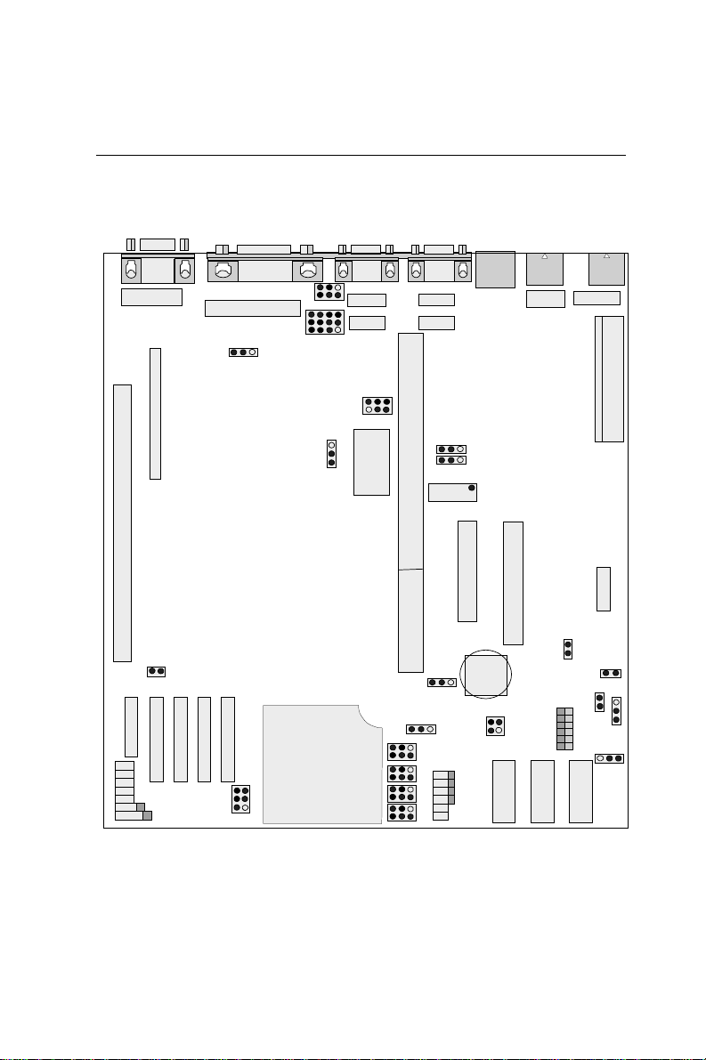
Locating Jumpers and Connectors
CN7
VGA
2 10
CN18
1 9
CN13
SIMM1
J17
SRAM 2ND LEVEL
CACHE MODULES
J34
J35
J36
J37
J38
J39
J40
CN6
PRINTER
14
CN10
1 13
J42
J3
JP33
J46
JP31
CPU
J47
CN5
COM1
CN9
CN12
BIOS
SLOT1
JP19
CN4
COM2
CN8
CN11
J12
1 2 1 2
CN16
33 34
J16
J22
J23
J24
J25
J30
J31
J26
J27
J28
J29
J8
J9
CN3
CN15
39 40
J41
SSD3
CN2
PS/2
KB
CN2A
SSD2
J48
SW1
SSD1
CN1
PS/2
KB
2
CN19
1 13
1
CN14
12
1 2
9 10
CN17
J18
J21
J20
J43
10 POS-460 User's Manual
Page 19

Safety Precautions
Warning! Always disconnect the power cord from your
chassis before you begin working on it. Do not
make connections while the power is on because
sensitive electronic components can be damaged
by the sudden rush of power . Only experienced
electronics personnel should open the PC chassis.
Caution! Always ground yourself to remove any static
charge before touching the CPU board. Modern
electronic devices are very sensitive to static
electric charges. Use a grounding wrist strap at all
times. Place all electronic components on a
static-dissipative surface or in a static-shielded
bag when they are not in the chassis.
Installing the CPU
The POS-460 All-in-one CPU module supports most 486 CPUs. The
system's performance depends upon the installed CPU. You can
install or upgrade the CPU in the board's PGA socket by following
the procedures outlined below.
Removing a CPU
1. Disconnect power from the chassis, and unplug all connections
to the CPU board. Consult your chassis' user's manual for
instructions on removing the CPU board.
2 . Unclip and lift the side lever of the CPU socket. Once the lever
is up, the CPU should be easy to remove.
Chapter 2 Installation 11
Page 20

Installing a CPU
Follow the installation instructions that came with your CPU. The
general procedures for installing a CPU are as follows:
1 . Unclip and lift the side lever of the CPU socket to an upright
position.
2 . Carefully align the CPU so that it is parallel to the socket. Make
sure that the notch on the corner of the CPU matches the notch
on the inside of the socket.
3 . Gently insert the CPU into the socket. There will probably be a
small gap between the CPU and the socket even when it is fully
seated. Lower the side lever to lock the CPU in place. Make
sure that the lever is clipped securely .
When you install a new CPU, you may have to adjust other
settings on the board, including CPU type, CPU clock, and PCI
speed. Make sure that the settings are correct for your CPU.
Improper settings may damage the CPU.
12 POS-460 User's Manual
Page 21
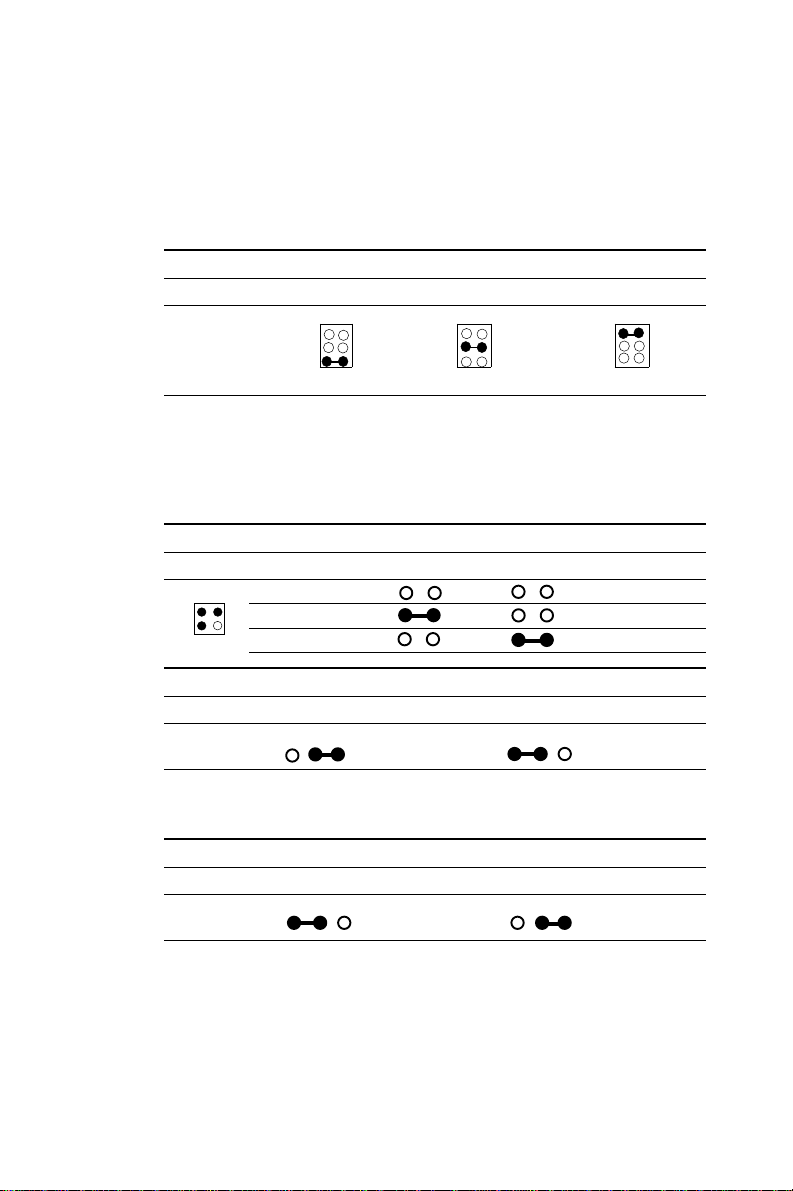
Setting Jumpers
You configure your board to match the needs of your application
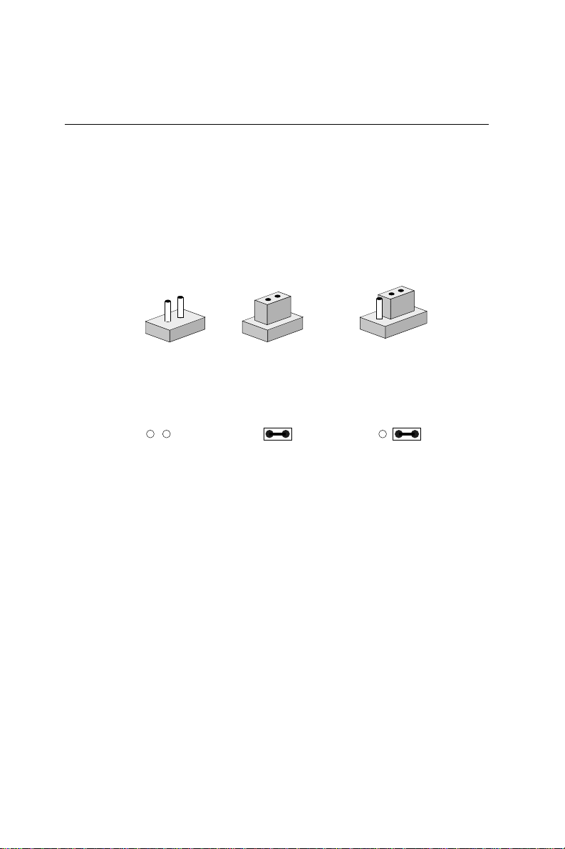
by setting jumpers. A jumper is the simplest kind of electric
switch. It consists of two metal pins and a small metal clip (often
protected by a plastic cover) that slides over the pins to connect
them. To “close” a jumper you connect the pins with the clip. To
“open” a jumper you remove the clip. Sometimes a jumper will
have three pins, labeled 1, 2, and 3. In this case you would
connect either pins 1 and 2 or 2 and 3.
2
1
Open Closed Closed 2-3
The jumper settings are schematically depicted in this manual as
follows:
Open Closed Closed 2-3
A pair of needle-nose pliers may be helpful when working with
jumpers.
1 2 3
3
If you have any doubts about the best hardware configuration for
your application, contact your local distributor or sales representative before you make any changes.
Generally, you simply need a standard cable to make most
connections.
Chapter 2 Installation 13
Page 22
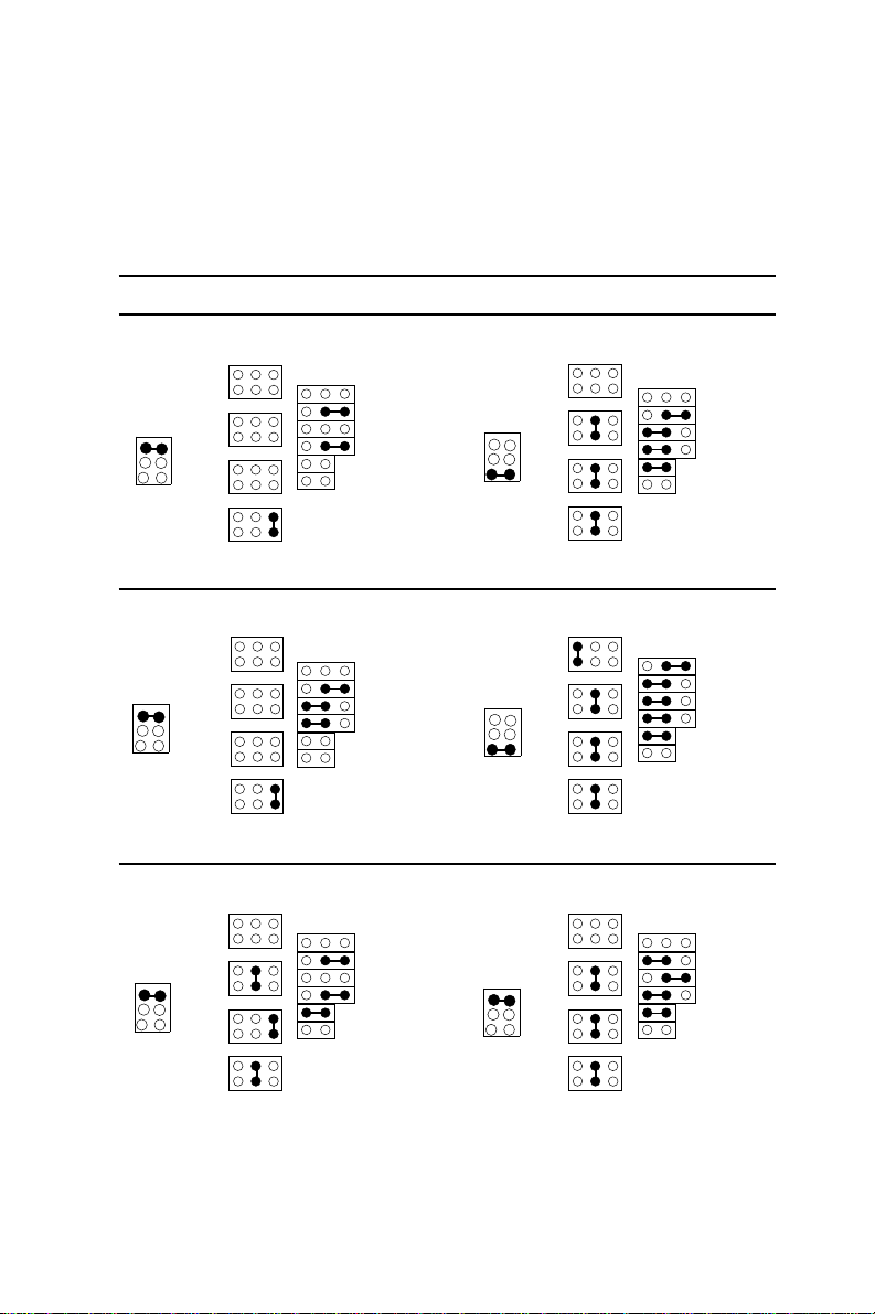
CPU type select (J22-J31)
The following diagrams show the correct jumper settings for
different CPUs.
CPU type select
Intel 486SX Intel/SGS DX4-S
531
J22
531
J23
531
J24
531
J25
CPU Voltage = 5V
6 5
4 3
2 1
J33
J22
J23
J24
J25
531
531
531
531
321
J30
J31
J26
J27
J28
J29
CPU Voltage = 3.45V
6 5
4 3
2 1
J33
321
J30
J31
J26
J27
J28
J29
Intel 486DX/DX2 Intel P24D, Cyrix 5x86 (M1-SC)
531
J22
531
J23
531
J24
531
J25
321
CPU Voltage = 5V
6 5
4 3
2 1
J33
J22
J23
J24
J25
531
531
531
531
321
J30
J31
J26
J27
J28
J29
CPU Voltage =3.45V
6 5
4 3
2 1
J33
Intel 486SX2-S Pentium ODP (P24T)
J22
J23
J24
J25
531
321
531
531
531
CPU Voltage = 5V
6 5
4 3
2 1
J33
531
J22
531
J23
531
J24
531
J25
321
14 POS-460 User's Manual
J30
J31
J26
J27
J28
J29
CPU Voltage = 5V
6 5
4 3
2 1
J33
J30
J31
J30
J31
J26
J27
J28
J29
J26
J27
J28
J29
Page 23
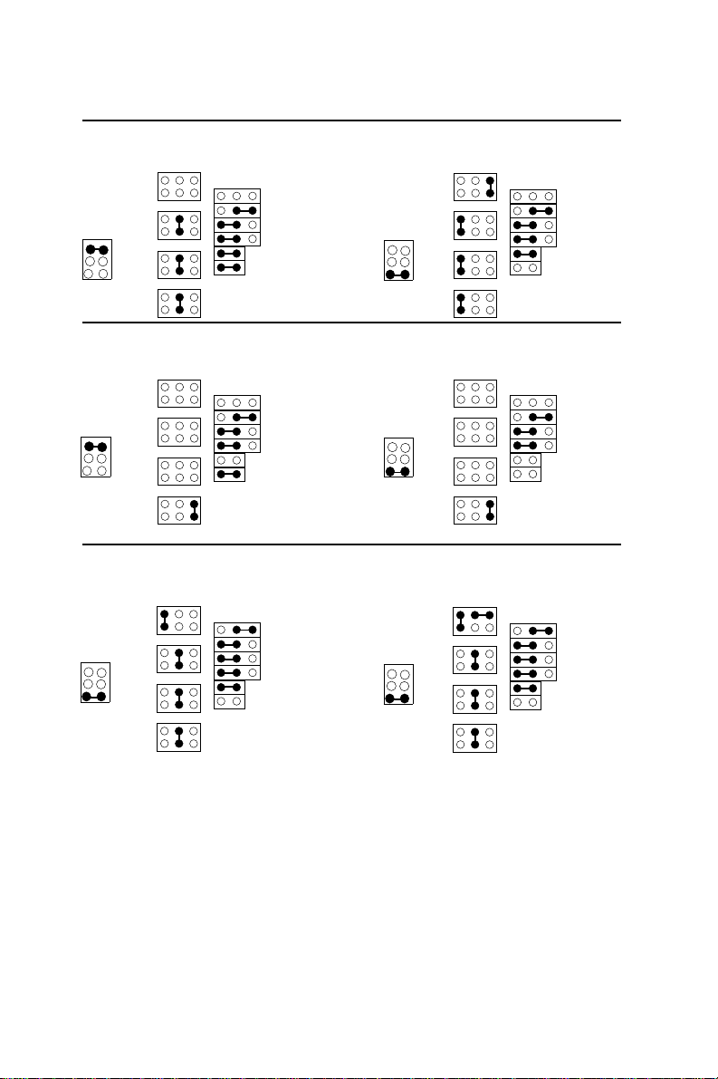
Intel 486DX-S/DX2-S IBM BL486DX2,
Cyrix 486DX2, and TI486DX/DX2
J22
CPU Voltage = 3.45V
6 5
4 3
2 1
J23
J24
J33
J25
CPU Voltage = 5V
6 5
4 3
2 1
J33
J22
J23
J24
J25
531
531
531
531
321
J30
J31
J26
J27
J28
J29
AMD 486DX/DX2 (none green) AMD 486DX4 <nv8t>
(none green)
CPU Voltage = 5V
6 5
4 3
2 1
J33
531
J22
531
J23
531
J24
531
J25
321
J30
J31
J26
J27
J28
J29
CPU Voltage = 3.45V
6 5
4 3
2 1
J33
J22
J23
J24
J25
AMD 486 DX4 <sv8b> AMD 486DX2<sv8b>,
AMD 5x86
CPU Voltage = 3.45V
6 5
4 3
2 1
J33
531
J22
531
J23
531
J24
531
J25
321
J30
J31
J26
J27
J28
J29
CPU Voltage = 3.45V
6 5
4 3
2 1
J33
J22
J23
J24
J25
531
531
531
531
531
531
531
531
531
531
531
531
321
J30
J31
321
J30
J31
321
J30
J31
J26
J27
J28
J29
J26
J27
J28
J29
J26
J27
J28
J29
Chapter 2 Installation 15
Page 24
CPU power supply select (J33)
J33 must be set to match the CPU type. The chart below shows the
proper jumper settings for their respective VCC.
CPU voltage select (J33)
CPU voltage 3.45 V 3.5 V 5 V
6 5
4 3
2 1
J33
6 5
4 3
2 1
J33
6 5
4 3
2 1
J33
CPU clock speed select (J41, JP19)
J41 and JP19 are used to synchronize the CPU clock with the CPU
type. Set the CPU clock according to the base CPU speed.
CPU clock speed select (J41)
CPU clock 1 - 2 3 - 4
43
21
J41
CPU clock speed select (JP19)
CPU > 33 MHz
25 MHz
33 MHz
40 MHz
≤≤
≤ 33 MHz
≤≤
321 321
CMOS discharge jumper (J16)
CMOS discharge jumper (J16)
Normal (default) Discharge
321 321
Note: To discharge CMOS, first make sure the power is
off. Move jumper J16 from 2-3 to 1-2 for a few
seconds so the CMOS can discharge. Move the
jumper back to 2-3.
16 POS-460 User's Manual
Page 25

AInstalling SIMM DRAM
Y ou can install between 1 MB to 32 MB of DRAM using a 1, 2, 4, 8,
16 or 32 MB 72-pin SIMM (Single In-Line Memory Module).
Access time should be 70 nsec. or less.
The SIMM can operate in conjunction with the optional 1 MB or 4
MB of on-board DRAM. Refer to the following page for details.
Installing a SIMM
NOTE: The module can only fit into a socket one wa y.
The gold pins must be pointing down into the
SIMM socket.
The procedure for installing a SIMM is outlined below.
1 . Ensure that all power supplies to the system are switched Off.
2 . Locate the board's memory bank, shown in the figure on
page 7.
3 . Install the SIMM module.
4 . Slip the SIMM into a socket at a 45 degree angle and carefully
fit the bottom of the board against the connectors.
5 . Gently push the SIMM into a perpendicular position until the
clips on the ends of the SIMM sockets snap into place.
6. Check to ensure that each SIMM is correctly seated and all
connector contacts touch. The SIMM should not move around
in its socket.
Chapter 2 Installation 17
Page 26

Optional On-board DRAM
With a volume order , the POS-460 can be affixed with 1 MB or 4 MB
on-board DRAM. The on-board DRAM and the SIMM type
DRAM can work together.
Cache Installation and Jumpers Set-
up (J17)
The cache memory system consists of two parts, one is TAG
SRAM, the other is DAT A SRAM. The TAG SRAM used in this
mainboard is 32Kx8 -15 ns and the DA T A SRAM is 64Kx8 -15/20 ns
or 128Kx8 -15/20 ns. The mainboard can be installed with 256 or
512 KB cache memory when using 64Kx8 or 128Kx8 type DA T A
SRAM respectively.
Cache Memory Size Setting
256K 512K
J17 open close
Data SRAM 64K8 x 4 pc. 128K8 x 4 pc.
TAG SRAM 32K8 32K8
Note: Make sure notch end on the chip matches notch end of the
socket when installing.
IDE Hard Drive Connector (CN15)
The built-in Enhanced IDE (Integrated Device Electronics) controller supports up to two IDE devices, including CD-ROM drives, tape
backup drives, a large hard disk drive and other IDE devices. It
also supports faster data transfer rates and allows IDE hard disk
drives with capacities in excess of 528 MB.
18 POS-460 User's Manual
Page 27

Connecting the hard drive
Connecting drives is done in a daisy-chain fashion. Wire number 1
on the cable is red or blue, while the other wires are gray.
1 . Connect one end of the cable to CN15. Make sure that the red
(or blue) wire corresponds to pin 1 on the connector, which is
labeled on the board (on the right side).
2 . Plug the other end of the cable into the Enhanced IDE hard
drive with pin 1 on the cable corresponding to pin 1 on the hard
drive. (See your hard drive's documentation for the location of
the connector.)
Connect a second drive as described above.
Unlike floppy drives, IDE hard drives can connect to either end of
the cable. If you install two drives, you will need to set one as the
master and one as the slave by using jumpers on the drives. If you
install just one drive, set it as the master.
Floppy Drive Connector (CN16)
You can attach up to two floppy disks to the POS-460's on-board
controller. You can use any combination of 5¼" (360 KB and 1.2
MB) and/or 3½" (720 KB, 1.44 MB, and 2.88 MB) drives.
A 34-pin daisy-chain drive connector cable is required for a dualdrive system. On one end of the cable is a 34-pin flat-cable connector. On the other end are two sets of floppy disk drive connectors.
Each set consists of a 34-pin flat-cable connector (usually used for
3½" drives) and a printed-circuit board connector (usually used for
5¼" drives).
Connecting the floppy drive
1 . Plug the 34-pin flat-cable connector into CN16. Make sure that
the red wire corresponds to pin one on the connector.
Chapter 2 Installation 19
Page 28

2. Attach the appropriate connector on the other end of the cable
to the floppy drive(s). You can use only one connector in the
set. The set on the end (after the twist in the cable) connects to
the A: drive. The set in the middle connects to the B: drive.
3 . If you are connecting a 5¼" floppy drive, line up the slot in the
printed circuit board with the blocked-off part of the cable
connector.
If you are connecting a 3½" floppy drive, you may have trouble
determining which pin is pin number one. Look for a number
printed on the circuit board indicating pin number one. Also,
the connector on the floppy drive connector may have a slot.
When the slot is up, pin number one should be on the right.
Check the documentation that came with the drive for more
information.
The B: drive can be attached to the connectors in the middle of
the cable as described above.
20 POS-460 User's Manual
Page 29

Primary Parallel Port Connector
(LPT1: CN6)
The primary parallel printer port is located at the rear edge of the
board with the DB-25 connector. The printer port is typically used
to connect a printer via an adapter cable. LPT1's IRQ is defined as
IRQ7. Y ou can select the LPT1 SPP/EPP/ECP selection mode from
BIOS (see Chapter 4).
You can select the DMA channel by setting J8 and J9.
DMA channel (J8, J9)
DMA1(default) DMA3
J8 3 2 1 3 2 1
.
J9 3 2 1 3 2 1
.
Secondary Parallel Port (LPT2: CN10)
The secondary parallel port is internally located next to the primary
parallel port with a 26-pin box header. The IRQ setting is selectable.
(See Secondary IRQ Selection, page 20.)
Keyboard Connector (CN1, CN2, CN2A)
The POS-460 provides 3-way parallel keyboard input via 2 external
mini DIN jacks (CN1 and CN2) and one internal 5-pin keyboard jack
(CN2A). The two external keyboard jacks are intended to accommodate several chassis arrangements. Only one external keyboard
port (CN1 or CN2) can be used at a given time - they cannot be
used simultaneously. The interior keyboard jack (CN2A) is a 5 pin
DIN for users to connect to the keyboard internally, for example, as
an all-in-one POS system. Pin assignment is shown in this manual's
appendix.
Chapter 2 Installation 21
Page 30

Front Panel Connectors
Y ou may want to install external switches to monitor and control
the POS-460. These features are completely optional — install them
only if necessary.
Front panel connection jumpers
J34 Power LED
J35 Reset switch
J36 HDD active LED
J37 Turbo LED
J38 Turbo switch
J39 Speaker
J40 Power LED and keyboard
LED1 Ethernet LED
Speaker
The POS-460 can drive an 8 Ω speaker at 0.5 watts. Ensure that
alternatives to this specification do not overload the board.
LED interface
The front panel LED indicator for hard disk access is an active low
signal (24 mA sink rate).
Reset switch
If you install a reset switch, it should be an open single pole
switch. Momentarily pressing the switch will activate a reset. The
switch should be rated for 10 mA, 5 V.
Power Connector (CN14)
The power connection is a 12-pin connector requiring ±5 V and ±12
V power. Remember to keep the ground wires (black color) toward
the middle when connecting the power wire from the power supply .
22 POS-460 User's Manual
Page 31

Serial Ports (COM1-4)
The POS-460 has a total of four on-board RS-232 serial ports,
COM1-4. They are differentiated by COM1 and COM2 as primary
serial ports and COM3 (RS-232/422/485) and COM4 as secondary
ports. All four serial ports have +5 V and +12 V power capabilities
on both pin #1 and pin #9, depending on the fuse placement.
Primary serial ports (COM1: CN5/CN9,
COM2: CN4/CN8)
Each primary serial port has two connections, one external DB-9
and one internal 10-pin header giving the user the flexibility to
adapt the board to many different systems. IRQ for COM1 and
COM2 is fixed with COM1 on IRQ4 and COM2 on IRQ3. COM1 and
COM2 can be enabled or disabled via BIOS (see Chapter 4).
Secondary serial ports
(COM3: CN11, COM4: CN6)
The secondary serial ports each have one 10-pin, internally
positioned header connection. The IRQ for both COM3 and COM4
is selectable (see below).
COM3 RS-232/422/485 setting (J42)
COM3 Pin
5 3 1
J42
6 4 2
RS-232 1-2
RS-422 3-4
RS-485 5-6
COM3 RS-232/422/485 setting (J46)
COM3 Pin COM3 Pin
12 9 6 3
J46
10 7 4 1
RS-422/485 1-2 RS-232 2-3
RS-422/485 4-5 RS-232 5-6
RS-422/485 7-8 RS-232 8-9
RS-422/485 10-11 RS-232 11-12
Chapter 2 Installation 23
Page 32

COM3, COM4, LPT2 enable/disable select (J47)
Port Pin Close Open
2 4 6
J47
1 3 5
COM3 1-2 Enable Disable
COM4 3-4 Enable Disable
LPT2 5-6 Enable Disable
Secondary I/O (COM3, COM4, LPT2) IRQ se-
lection (J12)
COM3, COM4 and LPT2 do not have defined IRQ settings. By
setting J12, users may choose from the IRQ selection choices
below:
Secondary I/O (COM3, COM4, LPT2) IRQ selection (J12)
Ports Close jumpers... IRQ selected
COM3 1-3 IRQ 11
3-5 IRQ 10
3-4 IRQ 12
COM4 5-7 IRQ 10
7-9 IRQ 9
7-8 IRQ 15
LPT2 4-6 IRQ 12
5-6 IRQ 10
6-8 IRQ 15
Jumper configuration
COM4 IRQ
IRQ9
97531
J12
10 8 6 4 2
IRQ15
X
Note: The above jumper arrangement will avoid second-
ary I/O's IRQ conflicts and mistakes.
24 POS-460 User's Manual
IRQ10
LPT2 IRQ
COM3 IRQ
IRQ11
XIRQ12
Page 33
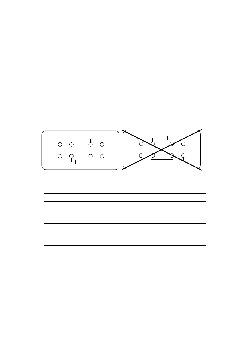
RS-232 serial ports (COM1-4) +5 V and +12
V power selection
All COM ports on the POS-460 have +5 V or +12 V capability on Pin
1 and Pin 9, depending on where you solder your fuse (fuse not
included). W e recommend using a 1 Amp fuse. To conserve board
space, the fuse mounts are positioned next to each other. To ensure
proper fuse placement, please observe the following example.
Typical fuse placement for the POS-460:
AL W A YS do this... NEVER do this !!!
Fuse on F17
F17 F16
F17 F16
Fuse on F16
Fuse installation chart for +5 V or +12 V power in COM
ports
F17 F16
F17 F16
Fuse on F16
Fuse on F17
Port Pin +5 V +12 V
COM1 Pin 1 F8 F9
Pin 9 F6 F7
COM2 Pin 1 F5 F4
Pin 9 F3 F2
COM3 Pin 1 F17 F16
Pin 9 F14 F15
COM4 Pin 1 F13 F11
Pin 9 F10 F12
Note: Only install the fuse if your peripheral requires it.
Unnecessary power in the serial port will damage
peripherals that do not require it.
Chapter 2 Installation 25
Page 34

VGA Interface Connections
The POS-460's SVGA interface can drive conventional CRT
displays and is capable of driving a wide range of flat panel
displays, including electroluminescent (EL), gas plasma, passive
LCD and active LCD displays. The board has two connectors to
support these displays, one for standard CRT VGA monitors and
one for flat panel displays.
On-board VGA hardware enable/disable
Enable Disable
J3 3 2 1 3 2 1
.
CRT display connector (CN7 and CN18)
CN7 is a standard 15-pin D-SUB connector commonly used for the
CRT VGA monitor . CN18 is a 10 pin header connector allowing user
to extend VGA connector elesewhere via customized cable. Pin
assignment appears in the appendix.
Flat panel display connector (CN13)
CN13 consists of a 44-pin, dual-in-line header. Power supplies
(+12 V, -12 V) present on CN13 depend upon the supply connected
to the board. (For more information on the proper connection
between CN13 and LCD, refer to chapter 3).
Configuration of the VGA interface is done completely via the
software utility. You don't have to set any jumpers. (Refer to
Chapter 3 for software setup details.)
Digital I/O (CN17: 2 outputs, 4 inputs)
The POS-460 uses digital I/O to customize its configuration to your
control needs. For example, you may configure the digital I/O to
26 POS-460 User's Manual
Page 35

control the opening and closing of the cash drawer or to sense the
warning signal from a tripped UPS. The following is a detailed
description of how the digital I/O is controlled via software
programming:
GND
IN-3
IN-2
IN-1
IN-0
97531
CN17
10 8 6 4 2
+12V GND Vcc(+5V)
OUT-1 OUT-0
Digital I/O programming (lattice installed
PLSI 1016)
Digital output is Open Collector type, meant to drive relays or
solenoids (50 VDC, 500 mA max.).
Output Address Bit
OUT-1 220 0
OUT-2 220 1
EXAMPLE:
DA T A 00 = OUT-0 & -1 = "0"
DARLINTON OUT-0 & -1 TURN OFF
DA T A 01 = OUT-0 = "1"
DARLINTON OUT-0 TURN ON
DA T A 02 = OUT-1 = "1"
DARLINTON OUT-1 TURN ON
DA T A 03 = OUT-0 & -1 = "1"
DARLINTON OUT-0 & -1 TURN ON
Input Address Bit
IN-0 220 0
IN-1 220 1
IN-2 220 2
IN-3 220 3
Chapter 2 Installation 27
Page 36

EXAMPLE: If INPUT 220 is [0111], then INPUT 3 is "0"
If INPUT 220 is [0011], then INPUT 3 & 4 are "0"
Note: The INPUT signal must be TTL compatible.
Ethernet Configuration
The POS-460 is equipped with a high performance 16-bit Ethernet
interface which is fully compliant with IEEE 802.3 10Mbps CSMA/
CD standards. It is supported by all major network operating
systems and is 100% Novell NE-2000 compatible.
Configuration of the Ethernet is very easy and can be done via the
DIAG9008.EXE program included on the utility disk. This program
enables you to view the current Ethernet configuration, to reconfigure the Ethernet interface (IRQ, I/O address, etc.), and to execute
useful diagnostic functions. (See Chapter 3 for detailed information)
The DIAG9008.EXE program provides ways to configure the
Ethernet interface without using jumpers. The following IRQ and I/
O address settings are available.
POS-460 Ethernet settings
IRQ option I/O address range
Jumperless 3, 4, 5, 7, 9, 1 0, 300H, 240H, 280H,
Configuration 11, 12 2C0H, 320H, 340H, 360H
Default Settings: IRQ = 5 ; I/O Address = 300H
Note: 1. Y ou can select an IRQ from the options shown
above, but make sure your selection does not
conflict with other I/O devices.
10BASE-T connector (CN3)
10BASE-T connects to the POS-460 via an adapter cable to the RJ45 standard jack (CN3) located at the rear of the board.
28 POS-460 User's Manual
Page 37

Network boot
The Network Boot feature is built into the BIOS. It can be enabled/
disabled in the chipset setup of the CMOS configuration. Please
refer to the BIOS setting in Chapter 4 for more information.
Watchdog Timer Configuration
An on-board watchdog timer reduces the chance of disruptions
which EMP (electro-magnetic pulse) interference can cause. This is
an invaluable protective device for standalone or unmanned
applications. Setup involves writing and running the control
software (refer to Appendix A).
Watchdog timer enable/disable
You can enable the watchdog timer by using your program to write
to the SSD's base address + 400h. (i.e. If the SSD address is 2D0h,
then read/write to address 6D0h.) Writing to the address enables
the watchdog, and reading from the address refreshes the watchdog. For information on programming the watchdog timer see
Appendix A.
Solid State Disk Configuration
The POS-460 features an internal Flash/ROM disk drive and
DiskOnChip 2000. This drive emulates a floppy disk drive by using
solid-state memory chips (Flash or EPROM) to store programs and
data instead of the magnetic particles on the mechanical drive’s
disk. The Flash/ROM disk and DOC 2000 offer much faster access
times than a floppy or hard disk and greatly increased reliability in
harsh environments.
The Flash/ROM disk/DOC 2000 works by modifying the BIOS
INT-13 disk I/O routine on boot-up. The routine then translates
read and write commands to the disk so that they will correctly
Chapter 2 Installation 29
Page 38

access the memory chips. You don’t need any special drivers. You
simply set the drive to act as a DOS drive (e.g. A: or C:) and use
standard DOS commands (COPY , DIR,etc) to manipulate your data.
Before you use the Flash/ROM disk, you will need to enable it with
SW1 and the BIOS Chipset Features Setup Program as detailed in
Chapter 4.
Memory devices
The Flash/ROM disk supports the following memory devices,
DiskOnChip 2000 series, or their equivalents:
• 27C010 128 Kb x 8 EPROM
• 27C040 512 Kb x 8 EPROM
• 28F010 128 Kb x 8 +12 V Flash Memory (AMD/INTEL)
• 29C010 128 Kb x 8 +5 V Flash Memory (A TMEL only)
• 29C040 512 Kb x 8 +5 V Flash Memory (A TMEL only)
• 29C040A 512 Kb x 8 +5 V Flash Memory (A TMEL only)
• MD-2200-DXX (DOC 2000 series)
If you use EPROM, files on the disk are read only . You will need an
external programmer to load your program and data files on the
EPROMs.
If you use +5 V Flash memories (29C010) for the solid state disk,
you can read or write data just like a floppy disk; you need not use
an external programmer. If you use +12 V Flash memories (28F010)
you will still need an external programmer to write data.
Before you activate the Flash/ROM drive (using the BIOS Chipset
Features Setup program), you will need to set the drive's I/O and
memory addresses to avoid conflicts with other plug-in cards. You
will also need to set the DOS drive designation to be used by the
Flash/ROM drive.
30 POS-460 User's Manual
Page 39

Note: If you use the DiskOnChip 2000 series, you must put it in the
SSD1 socket only .
Drive capacity
The size of the emulated drive depends on the size and number of
the chips you install. For example, if you install three 512 KB chips,
you will have 3 x 512 KB = 1.536 MB, equivalent to a 1.44 MB
floppy. The following table shows the memory chips you will need
to emulate 360 KB, 720 KB, 1.2 MB and 1.44 MB floppy drives.
Y ou will need to set jumpers JP18, JP20, J43, JP21 and J48 to match
the type (Flash, SRAM, ROM, or DOC 2000) and size (128 KB,
512 KB, or 2~12 MB for DOC 2000) of the devices you use. All the
devices must be the same type and size.
The following tables shows the size and number of devices you will
need for each size emulated disk. It also shows the corresponding
settings of jumpers JP18, JP20, J43, J21 and J48.
J20 J18 J21 J43 J48
SRAM 128K - Short Open 2-3 Open
SRAM 512K - Open Open 2-3 Open
FLASH 128K 2-3 Short Short 1-2 Open
FLASH 512K 2-3 Open Short 1- 2 Open
EPROM 128K 1-2 Short Short 1- 2 Open
EPROM 512K 1-2 Open Short 1 -2 Open
DiskOnChip 2-3 Open Short 1 - 2 Close
Chapter 2 Installation 31
Page 40

Drive configuration
Before you activate the Flash/ROM drive (using the BIOS Chipset
Features Setup program), you will need to set the drive’s I/O and
memory addresses to avoid conflicts with other plug-in cards. You
will also need to set the DOS drive designation to be used by the
Flash/ROM drive. DIP switch SW1 controls each of these settings,
as described in the following sections:
I/O address selection (SW1)
Positions 1 and 2 on DIP switch SW1 control the disk’s I/O
address.
Position 1 Position 2 I/O Address (hex)
Off Off 2D0
Off On 290
On Off 250
On On 210
Memory address selection (SW1)
The SSD occupies a window in the memory address range of D000:
0000-1FFF . Positions 3 and 4 on SW1 enable/disable the Flash/
ROM disk’s memory address. If you select “Disabled”, the disk will
not function.
Position 3 Position 4 SSD Function
Off Off Disabled
Off On Enabled
On Off Enabled
On On Enabled
Drive emulated (SW1)
Positions 5 and 6 of SW1 control the DOS drive emulated by the
Flash/ROM disk: 1st, 2nd, 3rd or 4th.
32 POS-460 User's Manual
Page 41

Position 5 Position 6 Drive
Off Off 4th
Off On 3rd
On Off 2nd
On On 1st
The actual drive letter assigned by DOS to the Flash/ROM disk
depends on the floppy or hard disks installed in the system. If you
are using a DOS version prior to DOS 5.0, the drive designation
may also differ .
DOS 5.0 (and later)
Floppy disks
The Flash/ROM disk will replace the corresponding floppy disk.
For example, if you have a single floppy disk (drive A) and assign
the Flash/ROM disk to be the first drive (both switches 5 and 6 are
on), any drive operations directed at drive A will go to the Flash/
ROM disk. This floppy drive will then be assigned the next free
drive designation. The example below illustrates this.
Hard disks
The Flash/ROM disk will not replace corresponding hard disks.
Instead, DOS will assign the Flash/ROM disk to the next free drive
designation. For example, if you have a single hard disk (drive C)
and assign the Flash/ROM disk to be the 3rd drive (switch 5 off,
switch 6 on), the Flash/ROM drive will become drive D. If you have
two hard disks, the Flash/ROM drive will become drive E.
Example 1
Installing the Flash/ROM disk as drive A (switches 5 and 6 are on).
Drive A B C D
Before FDD FDD HDD
After Flash/ROM FDD HDD FDD
Example 2
Y ou (try to) install the Flash/ROM disk as drive C.
Drive A B C D
Before FDD FDD HDD
After FDD FDD HDD Flash/ROM
Chapter 2 Installation 33
Page 42

Booting from the Flash/ROM disk
If you wish to have the system boot from the Flash/ROM disk,
simply set positions 5 and 6 on SW1 for the first FDD. Copy your
application files to the disk along with the standard system files
required to boot (command.com, io.sys, autoexec.bat, etc). The next
time you start the system, it will boot from the solid state disk.
Inserting memory devices
After you have set all the jumpers and switches on the POS-460,
insert the appropriate memory devices into the card’s sockets.
Remember that you will need to program EPROMs before you
insert them.
NOTE: The first SSD you install must be inserted into
DIP socket SSD1 (as shown in the diagram on
page 8), leaving SSD2 and SSD3 empty. Lik ewise, the second SSD must go into SSD2,
leaving SSD3 empty.
1 . Make sure that the pins of the memory chips are perpendicular
to the case and both rows are parallel to each other. Many times
the chips come with the pins spread out slightly . Place the chip
on a table top and carefully bend each line of pins together until
they point directly down.
2. Insert each chip. Align the chips so their pins are perpendicular
to the connector and the semicircular notch on the end of the
chip matches the notch on the end of the socket. There will
probably be a gap between the chip body and the socket when
it is fully seated – Do not push too hard!
Formatting the Solid State disk
34 POS-460 User's Manual
Page 43

If you use Flash memory or SRAM, it is advisable to format the
Flash/SRAM disk before copying files to it. The DOS command is
as follows:
FORMAT drv: /U ...
where drv = solid state disk drive A, B, C etc.
File copy utility
The utility program COOKROM.EXE, included on the card’s utility
disk, splits the files on a diskette into a series of binary files. You
can then use an external programmer to copy the files to EPROM or
+12 V Flash memory chips. It produces up to three files, depending
on the size of the source files.
Using a memory manager (EMM386.EXE)
If you are using an extended or expanded memory manager (such
as EMM386 or QEMM386), you will need to configure it to avoid
the addresses used by the Flash/ROM disk (set by positions 3 and
4 of SW1). Otherwise, the memory manager will attempt to use
these addresses, causing unreliable operation.
For example, the line in your CONFIG.SYS file that invokes
EMM386, the DOS memory manager, might be the following:
DEVICE=EMM386.SYS X=D600-D7FF
This excludes an 8 KB range for the card from D6000 to D7FFF (the
default addresses).
If you are using expanded memory , you will need to make sure that
the memory manager is not putting the page frame in the disk’s
addresses. For example,
DEVICE=EMM386.EXE X=D600-D7FF FRAME = D800
You should also make sure that the disk’s memory address is not
shadowed in the BIOS.
Chapter 2 Installation 35
Page 44

36 POS-460 User's Manual
Page 45

3
CHAPTER
VGA Display & Ether-
net Software Config-
uration
This chapter details the software configuration information. It shows you how to
configure the board to match your
application requirements. AWARD
System BIOS is covered in Chapter 4.
Sections include:
• LCD display configuration
• Connections for two standard LCDs
• Ethernet interface configuration
Chapter 3 Software Configuration 37
Page 46

Introduction
The POS-460 system BIOS and custom drivers are located in a
128 Kbyte, 32-pin (JEDEC spec.) Flash ROM device, designated
U33. A single Flash chip holds the system BIOS, VGA BIOS, and
network Boot ROM image. The display can be configured via
software. This method minimizes the number of chips and eases
configuration. Y ou can change the display BIOS simply by reprogramming the Flash chip.
POS-460 Utility Disk
The POS-460 is supplied with a software utility disk that holds the
necessary file for setting up the VGA display and Ethernet controller. The disk's directory and file structure is as follows:
ROOT
README.DOC
NET
DIAG9008.EXE
SSD
COOKROM.EXE
BIOS
460_SYS.BIN
AWDFLASH.EXE
DIAG9008.EXE
This program is the UMC9008 Ethernet controller AUTO-Scan/
Setup/Diagnostic function.
COOKROM.EXE
A program that converts application files into binary files (files with
a .BIN extension). These are then written into the SSD Flash ROM
devices.
460_SYS.BIN
This binary file contains the system BIOS.
38 POS-460 User's Manual
Page 47

AWDFLASH.EXE
This program allows you to write the Factory-Bundled System
BIOS/ VGA BIOS files to the BIOS Flash ROM. The VGA files are
already formatted for the POS-460 with .BIN extensions. See
README.DOC. These files support various CRT and flat panel
displays. They are custom written and are available upon request.
VGA BIOS Software Configuration
The POS-460’s on-board VGA BIOS is bundled at the factory with
the System BIOS and are together written into the BIOS Flash ROM
via the A WDFLASH.EXE utility software. The VGA BIOS supports a wide range of popular LCD, EL, gas plasma flat panel
displays and traditional analog CRT monitors. The VGA BIOS can
drive CRT displays with resolutions up to 1024 x 768 in 256 colors.
It is also capable of driving color panel displays with resolutions of
640 x 480 in 64K colors. If the VGA BIOS needs to be re-configured
for a special LCD, the system BIOS and the VGA BIOS need to be
re-configured together via the A WDFLASH.EXE utility . Most LCD
panels can be lit with the POS-460's standard VGA BIOS when the
LCD interface is connected. (See appendix for CN13 pin assignment).
In case the customer's LCD panel cannot work correctly with
standard VGA BIOS and we have the modified BIOS to support
their particular LCD, we can provide the file to the customer free of
charge. The customer can then use A WDFLASH.exe utility
program to update the VGA BIOS. If we do not have the modified
BIOS and the customer needs us to modify the BIOS for them, we
need the specific LCD to adjust BIOS parameters and to verify the
BIOS. The customer must ship their LCD to us, and a service
charge will apply for this custom modification.
Use A WDFLASH.exe to configure the VGA display as follows:
1 . Apply power to the POS-460 with a color TFT display attached.
This is the default setting for the POS-460. Ensure that the
A WDFLASH.EXE and *.BIN files are located in the working
drive.
NO TE : Ensure that you do not run AWDFLASH.EXE
while your system is operating in EMM386 mode.
Chapter 3 Software Configuration 39
Page 48
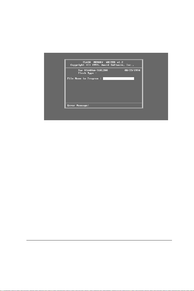
2 . At the prompt, type A WDFLASH.EXE and press <Enter>. The
VGA configuration program will then display the following:
VGA Setup screen
3 . At the prompt, type in the BIN file which supports your display.
When you are sure that you have entered the file name correctly press <Enter>. The screen will ask “Do you want to save?” If
you wish to continue press Y. If you change your mind or have
made a mistake press N to abort and end the setup procedure.
4 . If you decide to continue, the program will create a BIOS.OLD
file which contains the existing BIOS configuration. The prompt
will then ask “Are you sure you want to save new configuration?” Press Y if you want the new file to be written into the
BIOS. Press N to exit the program.
The new VGA configuration will then write to the ROM BIOS chip.
This configuration will remain the same until you run the
A WDFLASH.EXE program and change the settings.
Sample Connections for LCD
40 POS-460 User's Manual
Page 49

Note: Please consult your sales representative to see if Advantech
has the connection chart for your particular LCD.
Connections to Toshiba LTM09C016
(640 x 480 TFT Color LCD)
LTM09C016 POS-460 CN13
Pin Pin name Pin Pin name
CN1-1 NCLK 35 SHFCLK
CN1-2 GND 3 GND
CN1-3 R0 22 P13
CN1-4 GND 3 GND
CN1-5 R1 23 P14
CN1-6 GND 4 GND
CN1-7 R2 24 P15
CN1-8 GND 4 GND
CN1-9 G0 17 P8
CN1-10 GND 8 GND
CN1-11 G1 18 P9
CN1-12 GND 8 GND
CN1-13 G2 19 P10
CN1-14 GND 33 GND
CN1-15 NC — —
CN2-1 B0 11 P2
CN2-2 GND 33 GND
CN2-3 B1 12 P3
CN2-4 GND 34 GND
CN2-5 B2 13 P4
CN2-6 GND 34 GND
CN2-7 ENAB 37 M
CN2-8 GND 39 GND
CN2-9 VDD 5 +5 V
CN2-10 VDD 6 + 5 V
Chapter 3 Software Configuration 41
Page 50

Ethernet Software Configuration
The POS-460’s on-board Ethernet interface supports all major
network operating systems. I/O addresses and interrupts are easily
configured via the DIAG9008.EXE program. T o execute the configuration, to view the current configuration, or to run diagnostics, do
the following:
1 . Power the POS-460 on. Ensure that the DIAG9008.EXE file is
located in the working drive.
2 . At the prompt type DIAG9008.EXE and press <Enter>. The
Ethernet configuration program will then be displayed.
3 . This simple screen shows all the available options for the
Ethernet interface. Just highlight the option you wish to change
by using the Up and Down keys. To change a selected item,
press <Enter>, and a screen will appear with the available
options. Highlight your option and press <Enter>. Each
highlighted option has a helpful message guide displayed at the
bottom of the screen for additional information.
4. After you have made your selections and are certain it is the
configuration that you want, press ESC. A prompt will appear
asking if you want to save the configuration. Press Y if you
want to save.
The Ethernet Setup Menu also offers three very useful diagnostic
functions. These are:
1 . Run EEPROM test
2. Run Diagnostics on Board
3 . Run Diagnostics on Network
Each option has its own display screen which shows the format
and result of any diagnostic tests undertaken.
42 POS-460 User's Manual
Page 51

Chapter 3 Software Configuration 43
Page 52

44 POS-460 User's Manual
Page 53

4
CHAPTER
Award BIOS Setup
This chapter describes how to set BIOS
configuration data.
Chapter 4 Award BIOS Setup 45
Page 54

Getting Help
Press F1 to open a help window that describes the appropriate keys
to use and the possible selections for the highlighted item. Press
<Esc> to exit the help window .
Main Menu
When you enter the A ward BIOS CMOS Setup Utility , the main
menu will appear, allowing you to select from 10 setup functions
and two exit choices. Use the arrow keys to move among the items,
and press <Enter> to accept or enter a sub-menu.
R O M P C I / I S A B I O S (2 A 4 K D A K 9)
C M O S S E T U P U T I L I T Y
A W A R D S O F T W A R E , I N C .
STANDARD CMOS SETUP SETTING PASSWORD
BIOS FEATURES SETUP IDE HDD AUTO DETECTION
CHIPSET FEATURES SETUP SAVE & EXIT SETUP
POWER MANAGEMENT SETUP EXIT WITHOUT SAVING
PCI CONFIGURATION SETUP
LOAD BIOS DEFAULTS
LOAD SETUP DEFAULTS
ESC: QUIT ßàáâ: SELECT ITEM
F10: Save & Exit Setup (Shift)F2: Change Color
46 POS-460 User's Manual
Time, Date, Hard Disk Type....
Main Menu
Page 55

Standard CMOS Setup Menu
Use the arrows to highlight an item, and use <PgUp> and
<PgDn> to select the value for each item.
R O M P C I / I S A B I O S (2A4KDAK9)
S T A N D A R D C M O S S E T U P
A W A R D S O F T W A R E , I N C .
Date (mm:dd:yy) : Wed, Jan 17 1996
Time (hh:mm:ss) : 12 : 19 : 58
HARD DISKS TYPE SIZE CYLS. HEADS PRECOMP LANDZONE SECTORS MODE
Primary Masternone 0 0 0 0 0 0 N/A
Primary Slave none 0 0 0 0 0 0 N/A
Drive A : None
Drive B : None
Video : EGA/VGA
Halt On : All Errors
ESC : Quit ßàáâ : Select Item PU / PD / + / - : Modify
F1 : Help (Shift)F2 : Change Color
Base Memory : 640K
Extended Memory : 3072K
Other Memory : 384K
Total Memory : 4096K
Standard CMOS Setup
Time
The time format is <hour> <minute> <second>. The time is based
on the 24-hour military clock. For example, 1 P .M. is 13:00:00.
Hard Drive Type
Press <PgUp> or <PgDn> to select a numbered hard disk type, or
type the number and press <Enter>. If no hard disk has been
installed, select "NONE".
If your hard disk type is not listed, set the type as "User" to define
your own drive manually. Use the keyboard to enter the drive
information (CYLS, HEAD, etc.), which should be found in the
documentation from your hard disk vendor or manufacturer.
Chapter 4 Award BIOS Setup 47
Page 56

Video
This setting must match your display card and monitor type. It is
used for the primary system monitor. Although secondary monitors
are supported, you do not have to select the type in setup.
Halt on
The computer can be set to halt if an error is detected during setup.
No Errors When BIOS detects a non-fatal error , the system
boot will not stop.
All Errors The system boot will stop for any error that is
detected.
All But Keyboard The system boot will not stop for a keyboard error.
It will stop for all other errors
All But Diskette The system boot will not stop for a disk error. It
will stop for all other errors
All But Disk/Key The system boot will not stop for a keyboard or
disk error. It will stop for all other errors
BIOS Features Setup
R O M P C I / I S A B I O S (2A4KDAK9)
B I O S F E A T U R E S S E T U P
A W A R D S O F T W A R E , I N C .
Virus Warning : Disabled Video BIOS Shadow : Enabled
CPU Internal Cache : Enabled C8000-CFFFF Shadow : Disabled
External Cache : Enabled D0000-D7FFF Shadow : Disabled
Quick Power On Self Test : Enabled D8000-DFFFF Shadow : Disabled
Boot Sequence : A,C
Swap Floppy Drive : Disabled
Boot Up Floppy Seek : Disabled
Boot Up NumLock Status : On
Boot Up System Speed : High
Gate A20 Option : Fast
Memory Parity Check : Enabled
Typematic Rate Setting : Disabled
Typematic Rate (Chars/sec):6
Typematic Delay (Msec)) : 250
Security Option : Setup
PCI/VGA Palette Snoop : Disabled
OS Select For DRAM>64MB:Non-OS2
48 POS-460 User's Manual
Esc: Quit ßàáâSelect Item
F1 : Help PU/PD/+/-:Modify
F5 : Old Values (Shift)F2 : Color
F6 : Load BIOS Defaults
F7 : Load Setup Defaults
BIOS Features Setup
Page 57

Virus Warning
When enabled, any attempt to write to the hard drive's boot sector
or partition table will cause the system to halt and display an error
message.
CPU Internal Cache / External Cache
Enabling caches can speed memory access, depending on your
CPU/chipset design.
Quick Power On Self Test
Enabling this setting speeds the POST by causing BIOS to shorten
or skip some check items.
Boot Sequence
This determines which drive the computer searches first for the
disk operatong system.
Boot Up Floppy Seek
When enabled, BIOS will determine if the installed floppy drive is
40 tracks (360 KB) or 80 tracks (720 KB or more).
Boot Up System Speed
"Low" fixes the CPU clock at 33 MHz. "High" causes BIOS to refer
to the CPU clock jumper settings to find the correct clock speed.
Security Option
If you select "System", you will be prompted for a password every
time the system is booted or any time you try to enter CMOS
Setup. If you select "Setup", you will be prompted only when you
try to enter CMOS Setup.
Chapter 4 Award BIOS Setup 49
Page 58

Chipset Features Setup
R O M P C I / I S A B I O S (2A4KDAK9)
CHIPSET FEATURES S E T U P
C H I P S E T F E A T U R E S S E T U P
Auto Configuration : Enabled
AT-BUS Clock : 7.19 MHz
DRAM Read Timing : Slow
DRAM Write Timing : Fast
SRAM Read Timing : 3-1-1-1
SRAM Write Timing : 1 Wait
Hidden Refresh : Disabled
ISA I/O Recovery : Enabled
Fast-Back-To-Back : Enabled
On-Chip Local Bus IDE : Enabled
IDE Buffer for DOS & Win : Disabled
The 2nd Channel IDE : Enabled
IDE HDD Block Mode : Enabled
IDE Primary Master PIO : Auto
IDE Primary Slave PIO : Auto
IDE Secondary Master PIO : Auto
IDE Secondary Slave PIO : Auto
LAN Card Boot ROM : Disabled
Solid State Disk : Disabled
On-board FDD Controller : Enabled
On-board Serial Port 1 : COM1/3F8
On-board Serial Port 2 : COM2/2F8
On-board Parallel Port : 378H
On-board Parallel Mode : SPP
IR Function : UnUsed
Esc : Quit ßàáâ: Select Item
F1 : Help PU/PD/+/- : Modify
F5 : Old Values (Shift)F2 : Color
F6 : Load BIOS Defaults
F7 :Load Setup Defaults
Chipset Features Setup
AT-bus Clock
7.19 MHz Normal setting
PCICLK/3 For 25 MHz systems (DX-25, DX2-50, DX4-75)
PCICLK/4 For 33 MHz systems (DX-33, DX2-66, DX4-100, 5x86-
100/133)
PCICLK/5 For 40 MHz systems (DX-40, DX2-80, DX4-120)
PCICLK/6 Low AT-bus clock
PCICLK/8 Lowest AT -bus clock
IDE Primary/Secondary - Master/Slave PIO
BIOS can automatically detect IDE HDD accessing mode, or the
mode (0~4) can be set manually .
50 POS-460 User's Manual
Page 59

LAN Card Boot ROM
Enabled/disabled LAN BOOT ROM for on-board LAN function
Solid State Disk
Enabled/disabled on-board SSD funtions
Power Management Setup
R O M P C I / I S A B I O S (2A4KDAK9)
POWER MANAGEMENT SETUP
AWARD SOFTWARE, INC.
Power Management : Disable
PM Control by APM : Yes
Video Off Option : Susp,Stby-->Off
Video Off Method : V/H SYNC+Blank
HDD Power Down : Disable
Doze Mode : Disable
Standby Mode : Disable
Suspend Mode : Disable
VGA : OFF
FDD (3FXh) : ON
LPT & COM : LPT/COM
HDD (1FXh) : ON
NMI : OFF
IRQ3 (COM2) : ON
IRQ4 (COM1) : ON
IRQ5 (LPT2) : ON
**PM TIMERS**
**PM EVENTS**
IRQ6 (Floppy Disk) : ON
IRQ7 (LPT1) : O N
IRQ8 (RTC Alarm) : O F F
IRQ9 (IRQ2 Redirect) : ON
IRQ10 (Reserved) : OFF
IRQ11 (Reserved) : OFF
IRQ12 (PS/2 Mouse) : ON
IRQ13 (Coprocessor) : OFF
IRQ14 (Hard Disk) : ON
IRQ15 (Reserved) : ON
Esc : Quit ßàáâ : Select Item
F1 : Help PU/PD/+/- : Modify
F5 : Old Values (Shift)F2 : Color
F6 : Load BIOS Defaults
F7 : Load Setup Defaults
Power Management Setup
Video Off Method
V/H SYNC + Blank BIOS will turn off V/H SYNC when in Green mode.
Blank Screen The screen will go blank when in Green mode.
DPMS Support If your VGA card supports DPMS (Display Power
Management Signaling), you may select this to
reduce the monitor power consumption.
HDD Power Down
This function may be set from 1 to 15 minutes or disabled.
Chapter 4 Award BIOS Setup 51
Page 60

Suspend Mode
This function may be set from 10 seconds to 1 hour or disabled.
VGA, HDD, IRQ3 - 15
Y ou can choose whether or not power management will monitor
activity at each of these locations.
PCI Configuration Setup
ROM PCI/ISA BIOS (2A4KDAK9)
PCI CONFIGURA TION SETUP
A W ARD SOFTWARE, INC
PnP BIOS Auto-Config :Disabled
Slot 1 Using INT# : AUTO
Slot 2 Using INT # : AUTO
Slot 3 Using INT # :AUTO
1st Available IRQ : 10
2nd Available IRQ :11
3rd Available IRQ : 12
4th Available IRQ : 9
PCI IRQ Actived By :Level
PCI IDE 2nd Channel :Enabled
PCI IDE IRQ Map To :PCI-Auto
Primary IDE INT# : A
Secondary IDE INT # : B
PnP BIOS Auto Config:
Enable/Disabled PnP BIOS Auto-Config
The default value is Disable
CPU to PCI Write Buffer :Enabled
PCI to DRAM Buffer :Enabled
CPU to PCI Byte Merge :Disabled
↑↓→← :Select Item
ESC: Quit
F1: Help PU/PD/+/- :Modify
F5: Old Values (Shift) F2 :Color
F6: Load BIOS Defaults
F7: Load Setup Defaults
Slot 1-3 using INT #:
Auto-detects the PCI device's IRQ or let user set IRQ manually.
The default value is AUTO
Available IRQ
The default value is shown on the above table.
These available IRQs are mapped to be PCI INT # by BIOS for PCI
device automatically. If on IRQ device is used by ISA device then
the user must keep the IRQ out of the available table.
52 POS-460 User's Manual
Page 61

Load BIOS defaults
LOAD BIOS DEF AUL TS loads the default system values directly
from ROM. If the stored record created by the Setup program
becomes corrupted (and therefore unusable), these defaults will
load automatically when you turn the POS-460 on.
Setting Password
If you enabled security in the BIOS features Setup Menu, you will
need to set a password. At the prompt, enter a password of up to
eight characters. You will then be asked to retype the password for
confirmation. To disable the password, press <Enter> when you are
prompted for a password.
IDE HDD Auto-Detect
BIOS can detect the type of hard drive you have. If you don't use
this option, you must manually set up the hard drive in the Standard CMOS Setup.
Chapter 4 Award BIOS Setup 53
Page 62

54 POS-460 User's Manual
Page 63

CHAPTER
5
SVGA Setup
The POS-460 features an on-board flat
panel/VGA interface. This chapter
provides instructions for installing and
operating the software drivers on the
included display driver diskette.
Chapter 5 SVGA Setup 55
Page 64

Simultaneous Display Mode
The 65545 VGA BIOS supports monochrome LCD, EL, color
TFT and STN LCD flat panel displays. It also supports interlaced
and non-interlaced analog monitors (VGA color and VGA
monochrome) in high-resolution modes while maintaining
complete IBM VGA compatibility. Digital monitors (i.e. MDA,
CGA, and EGA) are NOT supported. Multiple frequency (multisync) monitors are supported as analog monitors.
Both CRT and panel displays can be used simultaneously. The
POS-460 can be set in one of three configurations: on a CRT, on
a flat panel display, or on both simultaneously. The system is
initially set to simultaneous display mode. In the utility diskette,
there are three .COM files which can be used to select the
display. Simply type the filename at the DOS prompt:
CT.COM Enables CRT display only
FP.COM Enables panel display only
SM.COM Enables both displays at the same time.
Sleep Mode
The display driver diskette contains two files that support sleep
mode. Simply type the filename at the DOS prompt:
ON.COM switches to normal display mode.
OFF.COM switches to sleep mode.
56 POS-460 User's Manual
Page 65

Software Support
The drivers support the following applications using the filenames and resolutions listed:
Application Filename Resolution Colors
Windows 3.1 LINEAR4.DRV 640x480 16
800x600 16
1024x768 16
LINEAR8.DRV 640x480 256
800x600 256
1024x768 256
LINEAR16.DRV 640x480 64K
LINEAR24.DRV 640x480 16M
AutoCAD R12 RCTURBOC.EXP 640x480 16
800x600 16
1024x768 16
640x480 256
800x600 256
1024x768 256
640x480 32K
640x480 64K
640x480 16M
Lotus 1-2-3 2.0 and Lotus Symphony 1.0,1.1
V132X25.DRV 132x25 (Text) 16
V132X50.DRV 132x50 (Text) 16
VESA 1.2 VESA.COM 800x600 16
1024x768 16
640x400 256
640x480 256
800x600 256
1024x768 256
640x480 32K
640x480 64K
Chapter 5 SVGA Setup 57
Page 66

Word 5.0 VGA600.VID 800x600 16
VGA768.VID 1024x768 16
Word 5.5 VGA55600.VID 800x600 16
VGA55768.VID 1024x768 16
WordPerfect 5.0 CHIPS600.WPD 800x600 16
CHIPS768.WPD 1024x768 16
WordPerfect 5.1 VGA600.VRS 800x600 16
VGA768.VRS 1024x768 16
Driver Installation
Necessary prerequisites
The instructions in this manual assume that you understand
elementary concepts of MS-DOS and the IBM Personal Computer. Before you attempt to install any driver or utility you should:
know how to copy files from a floppy disk to a directory on the
hard disk, understand the MS-DOS directory structure, and know
how to format a floppy disk. If you are uncertain about any of
these concepts, please refer to the DOS or Windows user reference guides for more information before you proceed with the
installation.
Before you begin
Before you begin installing software drivers, you should make a
backup copy of the display driver diskette and store the original
in a safe place. The display driver diskette contains drivers for
several versions of certain applications. You must install the
correct version in order for the driver to work properly so make
sure you know which version of the application you have.
58 POS-460 User's Manual
Page 67

Windows setup
These drivers are designed to work with Microsoft Windows 3.1.
You may install these drivers through Windows or in DOS.
Step 1: Install Windows as you normally would for a VGA
display. Run Windows to make sure that it is working correctly.
Step 2: Place the display driver diskette in drive A. In Windows
Program Manager, choose File from the Options Menu. Then
from the pull-down menu, choose Run . . . . At the command line
prompt, type A:\WINSETUP. Press the <ENTER> key or click
OK to begin the installation. At this point the setup program
locates the directory where Windows is installed. For proper
operation, the drivers must be installed in the Windows subdirectory. Press <ENTER> to complete the installation. Once completed, the Display Driver Control Panel appears on the screen. This
Control Panel allows you to select and load the installed drivers.
Another method of installing these drivers is through the File
Manager. Click on Drive A:. Then double-click on
WINSETUP.EXE to begin installation.
Changing Display Drivers in Windows
To change display drivers in Windows, select the Windows Setup
icon from the Main window. You will be shown the current setup
configuration. Select Change System Settings from the Option
menu. Click on the arrow at the end of the Display line. You will
be shown a list of display drivers. Click on the driver you want.
Then click on the OK button. Follow the directions to complete
the setup.
Changing Color Schemes
After you change display drivers, you may notice that the color
scheme used by Windows looks strange. This is because different
drivers have different default colors. To change the color scheme,
select the Control Panel from the Main window. Select the Color
icon. You will be shown the current color scheme. Choose a new
color scheme and click the OK button.
Chapter 5 SVGA Setup 59
Page 68

DOS Setup
Step 1: Install Windows as you normally would for a VGA
display. Run Windows to make sure that it is working correctly.
Then exit Windows.
Step 2: Place the display driver diskette in drive A. Type A:
<ENTER> to make this the default drive. Type SETUP <ENTER> to run the driver SETUP program. Press any key to get to
the applications list. Using the arrow keys, select Windows
Version 3.1 and press the <ENTER> key. Press the <ENTER>
key to select All Resolutions, and then press <END> to begin the
installation. At this point you will be asked for the path to your
Windows System directory (default C:\WINDOWS). When the
installation is complete, press any key to continue. Press <ESC>
followed by Y to exit to DOS.
Step 3: Change to the directory where you installed Windows
(usually C:\WINDOWS).
Step 4: Type SETUP <ENTER> to run the Windows Setup
program. It will show the current Windows configuration. Use
the up arrow key to move to the Display line and press <ENTER>. A list of display drivers will be shown. Use the arrow
keys to select one of the drivers starting with an asterisk (*) and
press <ENTER>.
Step 5: Follow the directions on the screen to complete the setup.
In most cases, you may press <ENTER> to accept the suggested
option. When Setup is done, it will return to DOS. Type WIN
<ENTER> to start Windows with the new display driver.
Changing Display Drivers in DOS
To change display drivers from DOS, change to the Windows
directory and run Setup, repeating steps 4 and 5 from the previous page. Besides the special display drivers marked by an
asterisk (*), you should be able to use the following standard
drivers:
VGA 640x480, 16 colors
Super VGA 800x600, 16 colors
60 POS-460 User's Manual
Page 69

Panning Drivers
Special panning drivers are provided to allow high-resolution
modes to be displayed on a flat panel or CRT. These drivers will
show a section of a larger screen and will automatically pan, or
scroll, the screen horizontally and vertically when the mouse
reaches the edge of the display.
Linear Acceleration Drivers
A special high-performance linear acceleration driver is provided
for 256-color modes. This driver may require special hardware
and may not be supported on all systems. It is only available for
Windows3.1.
Chapter 5 SVGA Setup 61
Page 70

AutoCAD R12
These drivers are designed to work with Autodesk AutoCAD
R12. They conform to the Autodesk Device Interface (ADI) for
Rendering drivers and Display drivers. These display list drivers
accelerate redraw, pan, and zoom functions.
Driver installation
Step 1: Place the display driver diskette in drive A. Type A:
<ENTER> to make this the default drive. Type SETUP <ENTER> to run the SETUP program. Press any key to get to the
applications list. Using the arrow keys, select AutoCAD Release
12 and press <ENTER>. This will display a list of supported
driver resolutions. Using the arrow keys and the <ENTER> key,
select the resolutions that are appropriate for your monitor. When
all of the desired resolutions have been selected, press <END> to
begin the installation. At this point you will be asked for a drive
and directory to copy the driver files. Enter the drive and directory that contains the installed AutoCAD R12. If the destination
directory does not exist you will be asked for confirmation. When
the installation is complete, press any key to continue. Press
<ESC> followed by Y to exit to DOS.
Step 2: Go to the AutoCAD directory where the new drivers were
installed and run the driver installation program by typing
ACAD12 -r <ENTER>. This program will configure your
AutoCAD R12 to use the new display drivers. Select TurboDLD
Classic.
Configuring TurboDLD
Select Configure Video Display. In Display Device Configura-
tion choose Select Graphics Board/Resolution. Then choose
Select Display Graphics Board. After choosing a graphics board,
go to Select Display Resolution. After selecting the display
resolution, save the new configuration, and return to the main
menu.
62 POS-460 User's Manual
Page 71

Basic Configuration Menu
This menu allows you to modify:
Number of AutoCAD Command Lines
Font Size 6x8/8x8/8x14/8x16/12x20/12x24
Dual Screen Enable/Disable
User Interface Configuration
Double Click Interval Time
BP Button
BP Highlight Patt Line/Xor Rect/Both
BP Refresh Enable/Disable
BP Cache Enable/Disable
Expert Configuration Menu
This menu allows you to modify:
Display List Enable/Disable
Drawing Cache Enable/Disable
Use Acad 31 bit space? Yes/No
Internal Command Echo Enable/Disable
BP Zoom Mode Freeze/Float
Regen Mode Incremental/Fast
If your previously installed driver is not TurboDLD, you will
have to reconfigure the RENDER command the first time you use
it.
Chapter 5 SVGA Setup 63
Page 72

Lotus 1-2-3 and Lotus Symphony
These drivers are designed to work with Lotus 1-2-3 versions 2.0,
2.01 and 2.2, and with Lotus Symphony versions 1.0 and 1.1.
Driver installation
Step 1: Place the display driver diskette into drive A. Make A the
default drive by typing A: <ENTER>. Run the SETUP program
by typing SETUP <ENTER>. Press any key to display a list of
supported applications. Use the arrow keys to select Lotus/
Symphony, and press <ENTER>. A list of supported screen
resolutions will be displayed. Use the arrow keys to select the
desired screen resolution and press <ENTER>. (Make sure your
monitor is able to display the resolution desired) Press <END> to
begin the driver installation process. A default drive and directory path will be displayed. Use the backspace key to erase this
default and type in the 123 directory. At this point you may be
asked to create the target directory if it does not already exist.
After the files have been installed, press any key to return to the
list of supported applications. Press <ESC> followed by Y to exit
to DOS. Copy all the files that were just created in the temporary
directory onto a formatted floppy diskette.
Step 2: Go to your 123 directory, and start the installation
program. Type the following commands:
C: <ENTER>
INSTALL <ENTER>
Step 3: The Lotus installation program will load and present the
installation menu. From this menu, select Advanced Options.
From the Advanced Options menu, select Add New Drivers To
Library. From the Add New Drivers Menu, select Modify
Current Driver Set. From the Modify Driver Set Menu, select
Text Display. From the Text Display menu, select one of drivers.
Step 4: After the selection of the appropriate VGA display driver,
you will need to exit this menu and return to the Main Lotus
Installation Menu. Do this by selecting Return To Menu.
Step 5: At the Main Lotus Installation Menu, select Save
Changes.
64 POS-460 User's Manual
Page 73

Step 6: At this point the Installation Menu will prompt you for
the name of your new Lotus configuration file. The Lotus system
will prompt you with the default value — 123.SET, but you may
want to use a filename that indicates the resolution of its driver.
For example, if you installed the 132 column by 25 line driver,
you could name this driver 132X25.SET, or if you installed the
80 by 50 driver, you may want to call the file 80X50.SET.
Step 7: The installation of your Lotus 1-2-3 driver is now
complete. You will need to exit the Lotus installation program at
this point. At the main Lotus Installation Menu, select Exit.
NOTE: If your driver set is not 123.SET, you have to type the
filename of your driver set in the command line when you start
Lotus 1-2-3. For example, if you named your driver set
132X25.SET, type the following to start Lotus 1-2-3:
123 132X25.SET <ENTER>
Chapter 5 SVGA Setup 65
Page 74

VESA
The Video Electronics Standards Association (VESA) has created
a standard for a Super VGA BIOS Extension (VBE). This defines
a standard software interface to allow application programs to set
and control extended video modes, such as 800x600 graphics, on
video adapters from different manufacturers.
The VESA driver adds this Super VGA BIOS Extension to the
VGA BIOS. Any application program which supports the VESA
standard driver interface can be used with this driver. This VESA
driver conforms to the VESA Super VGA Standard #VS891001.
Driver installation
Step 1: Place the display driver diskette into drive A. Make A the
default drive by typing A: <ENTER>. Run the SETUP program
by typing SETUP <ENTER>. Press any key to display a list of
supported applications. Use the arrow keys to select VESA
Driver Version 1.2 and press <ENTER>. Press the <ENTER>
key to select All Resolutions, and press <END> to begin the
installation. A default drive and directory path will be displayed.
Use the backspace key to erase this and type in a directory that is
in the directory path (such as C:\BIN or C:\UTILS). After the
files have been installed, press any key to return to the list of
supported applications. Press <ESC> followed by Y to exit to
DOS.
Step 2: To install the VESA driver, type either VESA <ENTER>
or VESA + <ENTER> at the DOS prompt. The optional +
command line parameter enables all of the available modes.
Make sure that your monitor is capable of displaying these high
resolution modes before enabling them.
NOTE: If the video BIOS already supports VBE extended video
modes, DO NOT use this driver. Run the VTEST.EXE program
to see if the video BIOS supports the VBE modes.
66 POS-460 User's Manual
Page 75

Word
These drivers are designed to work with Microsoft Word 5.0 and
5.5.
Driver installation
If you have already installed Word on your computer, go to Step
2 to install the new video driver.
Step 1: Install Word as normal.
Step 2: After you complete the Word installation, place the
display driver diskette into drive A. Make A the default drive by
typing A: <ENTER>. Run the SETUP program by typing
SETUP <ENTER>. Press any key to display a list of supported
applications. Use the arrow keys to select Word and press
<ENTER>. Use the arrow keys to select the desired screen
resolution and press <ENTER> (make sure your monitor is able
to display the resolution desired). Press <END> to begin the
driver installation process. A default drive and directory path will
be displayed. Use the backspace key to erase this and type in
your Word directory. After the files have been installed, press
any key to return to the list of supported applications. Press
<ESC> followed by Y to exit to DOS.
Step 3: Copy the driver file for the desired resolution that was
just installed to SCREEN.VID.
Chapter 5 SVGA Setup 67
Page 76

WordPerfect
These drivers are designed to work with WordPerfect 5.0 or 5.1.
They support 132-column display in editing mode, and highresolution graphics display in PreView mode.
Driver installation
Step 1: Place the display driver diskette into drive A. Make A the
default drive by typing A: <ENTER>. Run the SETUP program
by typing SETUP <ENTER>. Press any key to display a list of
supported applications. Use the arrow keys to select WordPerfect
and press <ENTER>. A list of supported screen resolutions will
be displayed. Use the arrow keys to select the desired screen
resolution and press <ENTER> (make sure your monitor is able
to display the resolution desired). Press <END> to begin the
driver installation process. A default drive and directory path will
be displayed. Use the backspace key to erase this default and type
in the WordPerfect directory. At this point you may be asked to
create the target directory if it does not already exist. After the
files have been installed, press any key to return to the list of
supported applications. Press <ESC> followed by Y to exit to
DOS.
Step 2: Start WordPerfect, and press <SHIFT>+<F1> to enter the
setup menu. Select D for Display and G for Graphics Screen
Type, and then choose the desired Chips VGA resolution.
68 POS-460 User's Manual
Page 77

Configuring WordPerfect 5.0 for 132 columns
Follow these instructions to configure WordPerfect 5.0 for 132
column text mode:
Step 1: To use the SETCOL program to set 132 columns and 25
rows, type the following command:
SETCOL 132, 25 <ENTER>
Step 2: Start WordPerfect. The program will detect the number
of rows and columns automatically. If for some reason WordPerfect is unable to adapt to 132 columns by 25 rows, start WordPerfect with the following command:
WP /SS=25,132 <ENTER>
Configuring WordPerfect 5.1 for 132 columns
Start WordPerfect and press <SHIFT>+<F1> to enter the setup
menu. Select D for Display and T for Text Screen Type and then
select Chips 132 Column Text.
Chapter 5 SVGA Setup 69
Page 78

70 POS-460 User's Manual
Page 79

APPENDIX
A
Programming the
Watchdog Timer
The POS-460 is equipped with a watchdog timer that resets the CPU if processing comes to a standstill for whatever
reason. This feature ensures system
reliability in industrial standalone, or
unmanned, environments.
Appendix A Programming the Watchdog Timer 71
Page 80

T o enable the watchdog timer , you must write a program which first
writes to the SSD's address + 400(hex) and then reads from that
address at regular intervals. The first time your program writes to
the port, it enables the watchdog timer. After that, your program
must read the port during a time interval of less than 1.6 seconds,
otherwise the watchdog timer will activate and reset the CPU.
If CPU processing comes to a standstill because of EMI or a
software bug, the program will signal to SSD address + 400(hex)
and the timer will be interrupted. The timer will then automatically
reset the CPU and data processing will continue normally.
You must write your program so that it reads the SSD's address +
400(hex) at an interval shorter than the timer's preset interval. The
timer's intervals have a tolerance of ±30%, so you should program
an instruction that will refresh the timer about every second.
The following program shows how you might program the watchdog timer in BASIC. If the SSD's base address is 2D0 (hex), then the
watchdog timer's address is 6D0 (hex):
10 REM Watchdog timer example program
20 X=IN (&H6D0) REM Enable the watchdog
30 GOSUB 1000 REM Task #1, takes 1.6 seconds to
40 X=OUT (&H6D0) REM Disable the watchdog
50 GOSUB 2000 REM Task #2, takes 1.6 second to
60 END
1000 REM Subroutine #1, takes 1.6 second to complete
1070 RETURN
2000 REM Subroutine #2, takes 1.6 second to complete
2090 RETURN
complete
complete
.
.
.
.
.
.
72 POS-460 User's Manual
Page 81

B
APPENDIX
Pin Assignments
This appendix contains information of a
detailed or specialized nature. It includes:
• Flat panel display connector
• Internal CRT connector
• Ethernet 10BASE-T connector
• IDE hard drive connector
• RS-232 connections
• Keyboard connectors
• ISA-slots
• Floppy drive connector
• Parallel port connector
• Digital input/output
• Main power connector
• Power LED and keylock
• Speaker
• IRQ Mapping
Appendix B Pin Assignments 73
Page 82

Flat panel display connector (CN13)
POS-460 Flat panel display connector
Pin Function Pin Function
1 +12 V 2 +12 V
3 GND 4 GND
5V
CC
7 ENAVEE 8 GND
9P0 10P1
11 P2 12 P3
13 P4 14 P5
15 P6 16 P7
17 P8 18 P9
19 P10 20 P11
21 P12 22 P13
23 P14 24 P15
25 P16 26 P17
27 P18 28 P19
29 P20 30 P21
31 P22 32 P23
33 GND 34 GND
35 SHFCLK 36 FLM
37 M/DE 38 LP
39 GND 40 ENABKL
41 NC 42 NC
43 NC 44 NC
6V
CC
VGA Internal Connector (CN18)
POS-460 Internal VGA connector
Pin Signal Pin Signal
1 RED 2 VGND
3 GREEN 4 VGND
5 BLUE 6 VGND
7 HSYNC 8 VGND
9 VSYNC 10 VGND
74 POS-460 User's Manual
Page 83

Ethernet AUI-BNC connector (CN19)
POS-460 Ethernet AUI-BNC connector
Pin Signal Pi n Signal
1 TD+ 11 TX2 TD- 12 BNC EN
3 RD+ 13 GND
4 RD- 14 V
CC
5NC
6 CD+
7 CD8 RX+
9 RX10 TX+
IDE hard drive connector (CN15)
POS-460 IDE hard drive connector
Pin Signal Pi n Signal
1 IDE RESET 2 GND
3DATA 7 4DATA 8
5DATA 6 6DATA 9
7DATA 5 8DATA 10
9 DATA 4 10 DATA 11
11 DATA 3 12 DATA 12
13 DATA 2 14 DATA 13
15 DATA 1 16 DATA 14
17 DATA 0 18 DATA 15
19 SIGNAL GND 20 N/C
21 N/C 22 GND
23 IO WRITE 24 GND
25 IO READ 26 GND
27 IO CHANNEL READY 2 8 BALE
29 N/C 30 GND
31 IRQ14 32 IOCS16
33 ADDR 1 34 N/C
35 ADDR 0 36 ADDR 2
37 HARD DISK SELECT 0 38 HARD DISK SELECT 1
39 IDE ACTIVE 40 GND
Appendix B Pin Assignments 75
Page 84

RS-232 connections (COM1: CN5/CN9,
COM2: CN4/CN8, COM3: CN12, COM4: CN11)
Different devices implement the RS-232 standard in different ways.
If you are having problems with a serial device, be sure to check
the pin assignments for the connector. The following table shows
the pin assignments for the board's RS-232 port.
POS-460 COM1-4 RS-232 serial ports COM3: CN12 RS-422/485
Pin Signal Pin Signal
1 DCD/+5 V/+12 V 1 TX2 RX 2 TX+
3 TX 3 RX+
4 DTR 4 RX 5 GND 5 GND
6 DSR 6 DSR
7 RTS 7 RTS
8 CTS 8 CTS
9 RI/+5 V/+12 V 9 RI/+5/+12V
9 8 7 6
5 4 3 2 1
COM1 - 2 Internal COM1-4
2 4 6 8 10
1 3 5 7 9
Keyboard connectors (CN2A, CN1, CN2)
POS-460 internal keyboard connector 5-pin header (CN2A)
Pin Function
1 K/B clock
2 K/B data
3 N/C
4 GND
5 +5 V
76 POS-460 User's Manual
DC
Page 85

External keyboard connectors (6-pin mini DIN) (CN1, CN2)
Pin Function
1 K/B data
2 N/C
3 GND
4 +5 V
DC
5 K/B clock
6 N/C
ISA slots (slot 1)
Board connector pin assignments - Side A
I/O pin Signal name Input/output
A1 -I/O CH CK Input
A2 SD7 Input/output
A3 SD6 Input/output
A4 SD5 Input/output
A5 SD4 Input/output
A6 SD3 Input/output
A7 SD2 Input/output
A8 SD1 Input/output
A9 SD0 Input/output
A10 I/O CHRDY Input
A11 AEN Output
A12 SA19 Input/output
A13 SA18 Input/output
A14 SA17 Input/output
A15 SA16 Input/output
A16 SA15 Input/output
A17 SA14 Input/output
A18 SA13 Input/output
A19 SA12 Input/output
A20 SA11 Input/output
A21 SA10 Input/output
A22 SA9 Input/output
A23 SA8 Input/output
A24 SA7 Input/output
Appendix B Pin Assignments 77
Page 86

Board connector pin assignments - Side A, cont.
I/O pin Signal name Input/output
A25 SA6 Input/output
A26 SA5 Input/output
A27 SA4 Input/output
A28 SA3 Input/output
A29 SA2 Input/output
A30 SA1 Input/output
A31 SA0 Input/output
Board connector pin assignments - Side B
I/O pin Signal name Input/output
B1 GND Ground
B2 RESET DRV Output
B3 +5 V
DC
Power
B4 IRQ9 Input
B5 -5 V
DC
Power
B6 DRQ2 Input
B7 -12 V
DC
Power
B8 OWS Input
B9 +12 V
DC
Power
B10 GND Ground
B11 -SMEMW Output
B12 -SMSMR Output
B13 -10 W Input/output
B14 -10 R Input/output
B15 -DRACK3 Output
B16 DRQ3 Input
B17 -DRACK1 Output
B18 DRQ1 Input
B19 -REFRESH Input/output
B20 CLK Output
B21 IRQ7 Input
B22 IRQ6 Input
B23 IRQ5 Input
B24 IRQ4 Input
B25 IRQ3 Input
78 POS-460 User's Manual
Page 87

Board connector pin assignments - Side B, cont.
I/O pin Signal name Input/output
B26 -DACK2 Output
B27 T/C Output
B28 BALE Output
B29 +5 V
DC
Power
B30 OSC Output
B31 GND Ground
Board connector pin assignments - Side C
I/O pin Signal name Input/output
C1 SBHE Input/output
C2 LA23 Input/output
C3 LA22 Input/output
C4 LA21 Input/output
C5 LA20 Input/output
C6 LA19 Input/output
C7 LA18 Input/output
C8 LA17 Input/output
C9 -MEMR Input/output
C10 -MEMW Input/output
C11 SD08 Input/output
C12 SD09 Input/output
C13 SD10 Input/output
C14 SD11 Input/output
C15 SD12 Input/output
C16 SD13 Input/output
C17 SD14 Input/output
C18 SD15 Input/output
Board connector pin assignments - Side D
I/O pin Signal name Input/output
D1 -MEM CSI6 Input
D2 -I/O CS16 Input
D3 IRQ10 Input
D4 IRQ11 Input
Appendix B Pin Assignments 79
Page 88

Board connector pin assignments - Side D, cont.
I/O pin Signal name Input/output
D5 IRQ12 Input
D6 IRQ15 Input
D7 IRQ14 Input
D8 -DACK0 Output
D9 DRQ0 Input
D10 -DACK5 Output
D11 DRQ5 Input
D12 -DACK6 Output
D13 DRQ6 Input
D14 -DACK7 Output
D15 DRQ7 Input
D16 +5 V
DC
Power
D17 -MASTER Input
D18 GND Ground
Floppy drive connector (CN16)
POS-460 Floppy drive connector
Pin Signal Pin Signal
1 GND 2 DENSITY SELECT
3 GND 4 N/C
5 GND 6 DRIVE TYPE
7 GND 8 INDEX
9 GND 10 MOTOR 0
11 GND 12 DRIVE SELECT 1
13 GND 14 DRIVE SELECT 2
15 GND 16 MOTOR 1
17 GND 18 DIRECTION
19 GN D 20 STEP
21 GND 22 WRITE DATA
23 GND 24 WRITE GATE
25 GND 26 TRACK 0
27 GND 28 WRITE PROTECT
29 GND 30 READ DAT A
31 GND 32 HEAD SELECT
33 GND 34 DISK CHANGE
80 POS-460 User's Manual
Page 89

Parallel port connector
(CN6: LPT1, CN10: LPT2)
POS-460 Parallel port connector
Pin Signal
1 \STROBE
2D0
3D1
4D2
5D3
6D4
7D5
8D6
9D7
10 \ACK
11 BUSY
12 PE
13 SLCT
14 AUTOFD
15 ERR
16 INIT
17 SLIN
18 GND
19 GND
20 GND
21 GND
22 GND
23 GND
24 GND
25 GND
26 NC
LPT1
LPT2
25 14
13 1
14 26
113
Appendix B Pin Assignments 81
Page 90

Digital input/output (CN17)
POS-460 digital I/O (CN17)
Pin Signal
1 I/O IN 0
2V
CC
3 I/O IN 1
4 I/O OUT 0
5 I/O IN 2
6 GND
7 I/O IN 3
8 I/O OUT 1
9 GND
10 +12 V
Main power connector (CN14)
POS-460 main power connector (CN14)
Pin Signal
1 Power good
2V
3 +12 V
4 -12 V
5 GND
6 GND
7 GND
8 GND
9 -5 V
11 V
12 V
CC
CC
CC
1
12
82 POS-460 User's Manual
1 2
Power Digital I/O
9 10
Page 91

Power LED and keylock (J40)
POS-460 power LED & keylock (J40)
Pin Signal
1V
CC
2 N/C
3 GND
4 Keylock
5 GND
Speaker (J39)
POS-460 speaker (J39)
Pin Signal
1V
CC
2 GND
3 GND
4 Speaker
IRQ Mapping Chart
IRQ Function
0 Interval timer
1 Keyboard
2 Interrupt from Controller 2
3 COM2
4 COM1
5 Ethernet
6 FDD
7 LPT1
8 RTC
9 Reserved for COM4
10 Reserved for COM3, COM4, or LPT2
11 Reserved for COM3
12 Reserved for COM3 or LPT2
13 INT from co-processor
14 IDE
15 Reserved for COM4 or LPT2
Appendix B Pin Assignments 83
Page 92

84 POS-460 User's Manual
 Loading...