

Page 1

PCA-6151
Half-size Pentium® CPU Card
with VGA Controller
Page 2

Copyright Notice
This document is copyrighted, 1996, by Advantech Co., Ltd. All
rights are reserved. Advantech Co., Ltd., reserves the right to make
improvements to the products described in this manual at any time
without notice.
No part of this manual may be reproduced, copied, translated, or
transmitted in any form or by any means without the prior written
permission of Advantech Co., Ltd. Information provided in this
manual is intended to be accurate and reliable. However,
Advantech Co., Ltd. assumes no responsibility for its use, nor for
any infringements upon the rights of third parties which may result
from its use.
Acknowledgements
Award is a trademark of Award Software International, Inc.
IBM, PC AT and VGA are trademarks of International Business
Machines Corporation.
Microsoft Windows® and MS-DOS are trademarks of Microsoft
Corporation.
SIS is a trademark of Silicon Integration Systems Corporation.
Intel is a trademark of Intel Corporation.
Part No. 2006151000 1st Edition
Printed in Taiwan November 1996
ii
Page 3

A Message to the Customer....
Advantech Customer Services
Each and every Advantech product is built to the most exacting
specifications to ensure reliable performance in the unusual and
demanding conditions typical of industrial environments. Whether
your new Advantech equipment is destined for the laboratory or
the factory floor, you can be assured that it will provide the
reliability and ease of operation for which the name Advantech has
come to be known.
Your satisfaction is our number one concern. Here is a guide to
Advantech’s customer services. To ensure you get the full benefit
of our services, please follow the instructions below carefully.
Technical Support
We want you to get the maximum performance from your
products. If you run into technical difficulties, we are here to help.
But please consult this manual first.
If you still can’t find the answer, gather all the information or
questions that apply to your problem and, with the product close at
hand, call your dealer. Our dealers are trained and ready to give
you the support you need to get the most from your Advantech
products. In fact, most problems reported are minor and are able to
be easily solved over the phone.
In addition, free technical support is available from Advantech
engineers every business day. We are always ready to give advice
on application requirements or specific information on the
installation and operation of any of our products.
iii
Page 4

Product warranty
Advantech warrants to you, the original purchaser, that each of its
products will be free from defects in materials and workmanship
for one year from the date of purchase.
This warranty does not apply to any products which have been
repaired or altered by other than repair personnel authorized by
Advantech, or which have been subject to misuse, abuse, accident
or improper installation. Advantech assumes no liability as a
consequence of such events under the terms of this Warranty.
Because of Advantech’s high quality-control standards and
rigorous testing, most of our customers never need to use our
repair and replacement service. If an Advantech product ever does
prove defective, it will be repaired at no charge during the
warranty period. For out-of-warranty repairs, you will be billed
according to the cost of replacement materials, service time and
freight. Please consult your dealer for more details.
If you think you have a defective product, follow these steps:
1.Collect all the information about the problem encountered (e.g.
type of PC, CPU speed, Advantech products used, other hardware
and software used etc.). Note anything abnormal and list any onscreen messages you get when the problem occurs.
2.Call your dealer and describe the problem. Please have your
manual, product and any other information readily available.
3.If your product is diagnosed as defective, obtain an RMA (return
material authorization) number from your dealer. This allows us to
process your return more quickly.
4.Carefully pack the defective product, a completely filled-out
Repair and Replacement Order Card and a photocopy of a dated
proof of purchase (such as your sales receipt) in a shippable
container. A product returned without dated proof of purchase is
not eligible for warranty service.
5.Write the RMA number visibly on the outside of the package
and ship it prepaid to your dealer.
iv
Page 5

Packing list
Before you begin installing your card, please make sure that the
following materials have been shipped:
• 1 PCA-6151 CPU card
• 1 6-pin mini-DIN keyboard & PS/2 mouse adapter
• 2 Hard disk drive (IDE) interface cables (40-pin)
• 1 Parallel / 1 Serial port cable adapter
• 1 Floppy disk drive interface cable (34-pin)
If any of these items are missing or damaged, contact your
distributor or sales representative immediately.
v
Page 6

Contents
Chapter 1 Hardware Configuration ....................... 1
Introduction............................................................................ 2
Specifications.......................................................................... 3
Board Layout.......................................................................... 4
Jumpers and Connectors....................................................... 5
Jumper Settings...................................................................... 7
How to set jumpers .................................................................. 7
CPU type select........................................................................ 8
CPU voltage select................................................................... 9
Watchdog timer (J29) .............................................................. 9
COM2 setting for RS-232/422/485 (J35~39) ........................ 10
CMOS backup select ............................................................. 10
Buzzer enable/disable ............................................................ 10
Chapter 2 Connecting Peripherals...................... 13
Enhanced IDE connectors (CN4) ....................................... 15
VGA interface connection (CN12)...................................... 15
Floppy Drive (CN8).............................................................. 16
Parallel Port (CN5) .............................................................. 16
Keyboard & PS/2 Mouse (CN14) ....................................... 17
Reset Switch (J14) ................................................................ 17
Hard Drive LED (CN6) ....................................................... 17
Serial Ports ........................................................................... 17
RS-232 connection (COM1) .................................................. 18
RS-232/422/485 connections (COM2) .................................. 19
Power connectors (CN11)...................................................... 19
vi
Page 7

Chapter 3 Award BIOS Setup .............................. 21
Entering setup ........................................................................ 22
Standard CMOS setup ........................................................... 23
BIOS features setup ............................................................... 24
CHIPSET features setup ........................................................ 28
Power management setup ...................................................... 29
Load BIOS defaults ............................................................... 30
Load setup defaults ................................................................ 30
Password setting .................................................................... 32
IDE HDD auto detection........................................................ 32
Save & Exit setup .................................................................. 32
Exit without saving ................................................................ 32
Appendix A Programming the Watchdog Timer ... 33
Appendix B Upgrading ............................................ 35
Installing PC/104 modules................................................... 36
Installing DRAM SIMMs .................................................... 37
vii
Page 8

viii
Page 9

1
CHAPTER
Hardware
Configuration
This chapter gives background
information on the PCA-6151. It then
shows you how to configure the card to
match your application and prepare it for
installation into your PC.
Sections include:
• Card specifications
• Board layout
• Safety precautions
• Jumper settings
• Installing DRAM (SIMMs)
Chapter 1 Hardware Configuration 1
Page 10

Introduction
The PCA-6151 is a cost-effective, all-in-one single board Pentium
CPU card which can release Pentium’s full potential and provide
unprecedented performance compared to current 64-bit processor
board. The PCA-6151 offers all the functions of an industrial
computer on a single board, half-size CPU card. This card uses a
Pentium, AMD K5 CPU or Cyrix M1 and can have up to 64 MB
DRAM. It also supports PB-SRAM 2nd level cache size from 256KB
to 512KB through an on board COAST module.
The PCA-6151 utilizes a two-chip solution, allowing on board DRAM
to be shared with the built-in VGA controller. In this configuration
the chipset always acts as the arbiter between memory bus masters.
This system insures efficient memory allocation while substantially
reducing the overall system cost.
On-board features include one RS-232 port, one RS-232/422/485 port,
one multi-mode parallel (ECP/EPP/SPP) port, a floppy drive controller and a keyboard & PS/2 mouse interface. The built-in high speed
PCI IDE controller supports both PIO and bus master modes. Up to
two IDE devices can be connected, including large hard disks,
CD-ROM drives, tape backup drives and other IDE devices.
The PCA-6151 also features power management to minimize power
consumption. It complies with the ”Green Function” standard and
supports three types of power saving features: Doze mode, Standby
mode and Suspend mode. A watchdog timer can automatically reset
the system or generate an interrupt should the system stop due to a
program bug or EMI.
2 PCA-6151 User's Manual
Page 11

Specifications
System
• CPU: Intel Pentium 75/90/100/120/133/150/166/200 MHz
AMD K5, Cyrix M1
• BIOS: AWARD 128 KB memory; supports plug and play
• Chipset: SiS 5596/5513
• L2 cache: Direct map write-back or write-through cache module
- 256 KB/512 KB Synchronous (Pipeline Burst) SRAM
• Green function: Features power management option via BIOS,
activated by keyboard or mouse activity. Supports doze, sleep and
suspend modes. APM 1.1 compliant
• RAM: Two 72-pin SIMM sockets. Supports 32-bit Normal or EDO
DRAM with memory capacity from 1 MB to 64 MB.
• EIDE interface: Handles up to two IDE HDDs (up to 8.4 GB) or
other IDE devices. Supports PIO mode 4 and DMA bus-master
mode
• FDD interface: Supports up to two floppy disk drives.
• Parallel port: Configured to LPT1, LPT2, LPT3 or disabled.
- Supports multi-mode parallel port (SPP/ECP/EPP)
• Serial ports: Two 16C550 UARTs, one RS-232,
one RS-232/422/485 interface
• Watchdog timer: Can generate a system reset or IRQ 15. Software
enabled/disabled. Time interval is from 1 to 63 seconds, jumperless
with run-time setup
• Keyboard/mouse connector: 6-pin mini-DIN connector on the
mounting bracket eases connection to a keyboard or PS/2 mouse.
An on-board keyboard pin header connector is also available.
• I/O bus expansion: PC/104 connector with face-up installation
Mechanical and environmental
• Board size: 185 mm x 122 mm
• Max. power requirements: +5 V (4.75 ~ 5.25 V) @ 5.5 A
• Operating temperature: 32 ~ 140° F (0 ~ 60° C)
• Board weight: 1.2 lb (0.5 kg)
Chapter 1 Hardware Configuration 3
Page 12

Board Layout
4 PCA-6151 User's Manual
Page 13

Jumpers and Connectors
Connectors on the board link it to external devices such as hard disk
drives, a keyboard, or floppy drives. In addition, the board has
jumpers which you use to configure it for your application.
The table below lists the function of each of the board jumpers and
connectors. Later sections in this chapter give instructions on setting
jumpers and detailed information on each jumper setting. Chapter 2
gives instructions for connecting external devices to your card.
PCA-6151 Jumpers
Number Function
J2 CPU Power select
J3 CPU Clock Ratio
J4 CPU Clock Ratio
J5 Clock select
J6 Fan Power select
J7 Watchdog timer invoke function
J8 COM2 output select
J9 COM2 output select
J10 COM2 output select
J11 COM2 output select
J12 COM2 output select
J13 CMOS Setup
J14 Reset Input
J16 Speaker connector
PCA-6151 Connectors
Number Function
CN1 KB Lock
CN2 PC104 Con. A
CN3 PC104 Con. B
CN4 IDE connector
CN5 Printer connector
CN6 HD LED
CN7 Peripheral Power Input
CN8 FDD connector
CN9 COM2 connector
CN10 Aux. Keyboard connector
CN11 Main Power Input
CN12 VGA connector
CN13 COM1 connector
CN14 Keyboard & P/S2 Mouse connector
Chapter 1 Hardware Configuration 5
Page 14

Safety Precautions
Follow these simple precautions to protect yourself from harm and
your PC from damage.
1. To avoid electric shock, always disconnect the power from your
PC chassis before you work on it. Don’t touch any components on
the CPU card or other cards while the PC is on.
2. Disconnect power before making any configuration changes. The
sudden rush of power as you connect a jumper or install a card
may damage sensitive electronic components.
3. Always ground yourself to remove any static charge before you
touch your CPU card. Be particularly careful not to touch the chip
connectors. Modern integrated electronic devices, especially CPUs
and memory chips, are extremely sensitive to static electric
discharges and fields. Keep the card in its antistatic packaging
when it is not installed in the PC, and place it on a static
dissipative mat when you are working with it. Wear a grounding
wrist strap for continuous protection.
6 PCA-6151 User's Manual
Page 15

Jumper Settings
This section tells how to set the jumpers to configure your card. It
gives the card default configuration and your options for each jumper.
After you set the jumpers and install the card, you will also need to
run the BIOS Setup program (discussed in Chapter 3) to configure the
serial port addresses, floppy/hard disk drive types and system
operating parameters. Connections, such as hard disk cables, appear in
Chapter 2.
For the locations of each jumper, see the board layout diagram
depicted earlier in this chapter.
How to set jumpers
You configure your card to match the needs of your application by
setting jumpers. A jumper is the simplest kind of electric switch. It
consists of two metal pins and a small metal clip (often protected by a
plastic cover) that slides over the pins to connect them. To “close” a
jumper you connect the pins with the clip. To “open” a jumper you
remove the clip. Sometimes a jumper will have three pins, labeled 1, 2
and 3. In this case you connect either pins 1 and 2 or 2 and 3.
2
1
3
OpenOpen
Open
OpenOpen
ClosedClosed
Closed
ClosedClosed
Closed 2-3Closed 2-3
Closed 2-3
Closed 2-3Closed 2-3
You may find pair of needle-nose pliers useful for setting the jumpers.
If you have any doubts about the best hardware configuration for your
application, contact your local distributor or sales representative
before you make any changes.
Chapter 1 Hardware Configuration 7
Page 16
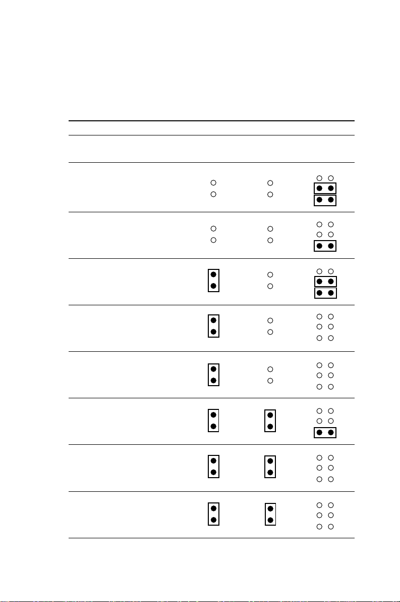
CPU type select (J3, J4, J6, J7, J8)
In order for the system to function properly, the jumpers must be set
to accommodate the CPU installed on the CPU card.
CPU type select (J3, J4, J5)
Pentium CPU J3 J4 J5
AMD K5, Cyrix M1
75 MHz
1.5 x 50
90 MHz
1.5 x 60
100 MHz
2 x 50
120 MHz
2 x 60
133 MHz
2 x 66
150 MHz
2.5 x 60
166 MHz
2.5 x 66
200 MHz
3 x 66
8 PCA-6151 User's Manual
Page 17

CPU voltage select (J1, J2)
CPU voltage select (J2)
Voltage J2
3.3 V
3.45 V
Watchdog Timer (J7)
Watchdog timer system reset/IRQ 15 select (J7)
Reset (default) IRQ 15
J7
Chapter 1 Hardware Configuration 9
Page 18

COM2 settings for RS-232/422/485 (J8~12)
COM2 settings for RS-232/422/485 (COM2)
RS-232 RS-422 RS-485
J8
J9
J10
J11
J12
CMOS backup select (J13)
Battery Backup (default) Clean CMOS
J13
Buzzer enable/disable (J16)
Enable Disable
J16
10 PCA-6151 User's Manual
Page 19

Installing DRAM (SIMMs)
On the left end of the card (away from the mounting bracket) are the
two SIMM(Single In-line Memory Module) sockets that hold the
card’s DRAM memory. See the board layout diagram depicted earlier
in this chapter.
You can use anywhere from 1 MB to 64 MB of DRAM with your
PCA-6151. The card provides two 72-pin SIMM sockets that accept
from 1 to 32 MB each. The sockets (numbered from 1 to 2) are
arranged into two banks.
Chapter 1 Hardware Configuration 11
Page 20

12 PCA-6151 User's Manual
Page 21

2
CHAPTER
Connecting
Peripherals
This chapter tells how to connect
peripherals, switches and indicators to the
PCA-6151 board. You can access most of
the connectors from the top of the board
while it is installed in the chassis. If you
have a number of cards installed, or your
chassis is very tight, you may need to
partially remove the card to make all the
connections.
Chapter 2 Connecting Peripherals 13
Page 22

The following table lists the connectors on the PCA-6151.
Connectors
Number Function
CN1 KB Lock
CN2 PC/104 Con. A
CN3 PC/104 Con. B
CN4 IDE Connector
CN5 Printer Connector
CN6 HD LED
CN7 Peripheral Power Input
CN8 FDD Connector
CN9 COM2 Connector
CN10 Aux. Keyboard Connector
CN11 Main Power Input
CN12 VGA Connector
CN13 COM1 Connector
CN14 Keyboard and PS/2 Mouse Connector
The following sections tell how to make each connection. In most
cases, you will simply need to connect a standard cable.
Warning! Always completely disconnect the power cord
from your chassis whenever you are working on
it. Do not make connections while the power is
on. Sensitive electronic components can be
damaged by the sudden rush of power. Only
experienced electronics personnel should open
the PC chassis.
Caution! Always ground yourself to remove any static
charge before touching the CPU card. Modern
electronic devices are very sensitive to static
electric charges. Use a grounding wrist strap at
all times. Place all electronic components on a
static-dissipative surface or in a static-shielded
bag when they are not in the chassis.
14 PCA-6151 User's Manual
Page 23

Enhanced IDE connectors (CN4)
You can attach two IDE (Integrated Device Electronics) drives to
the PCA-6151’s internal controller. The PCA-6151 CPU card has
an EIDE connector, CN4.
Wire number 1 on the cable is red or blue, the other wires are gray.
Connect one end to connector CN4 on the CPU card. Make sure
that the red (or blue) wire corresponds to pin 1 on the connector
(on the right side). See Chapter 1 for help finding the connector.
Unlike floppy drives, IDE hard drives can connect in either
position on the cable. If you install two drives, you will need to set
one as the master and one as the slave. You do this by setting the
jumpers on the drives. If you use just one drive, you should set it
as the master. See the documentation that came with your drive for
more information.
Connect the first hard drive to the other end of the cable. Wire 1
on the cable should also connect to pin 1 on the hard drive
connector, which is labeled on the drive circuit board. Check the
documentation that came with the drive for more information.
Connect the second drive as described above on CN4.
VGA display connector (CN12)
The PCA-6151 provides a VGA controller for high resolution
VGA interface. CN12 is a DB-15 connector for VGA monitor
input.
Chapter 2 Connecting Peripherals 15
Page 24

Floppy drive connector (CN8)
You can attach up to two floppy disk drives to the PCA-6151’s
on-board controller. You can use any combination of 5.25"
(360 KB/1.2 MB) and/or 3.5" (720 KB/1.44/2.88 MB) drives.
The card comes with a 34-pin daisy-chain drive connector cable.
On one end of the cable is a 34-pin flat-cable connector. On the
other end are two sets of floppy disk drive connectors. Each set
consists of a 34-pin flat-cable connector (usually used for 3.5"
drives) and a printed-circuit-board connector (usually used for
5.25" drives). You can use only one connector in each set. The set
on the end (after the twist in the cable) connects to the A: floppy.
The set in the middle connects to the B: floppy.
Parallel port connector (CN5)
The parallel port is normally used to connect the CPU card to a
printer. The PCA-6151 includes an on-board parallel port,
accessed through a 26-pin flat-cable connector, CN5. The card
comes with an adapter cable which lets you use a traditional
DB-25 connector. The cable has a 26-pin connector on one end
and a DB-25 connector on the other, mounted on a retaining
bracket. The bracket installs at the end of an empty slot in your
chassis, giving you access to the connector.
To install the bracket, find an empty slot in your chassis. Unscrew
the plate that covers the end of the slot. Screw in the bracket in
place of the plate. Next, attach the flat-cable connector to CN5 on
the CPU card. Wire 1 of the cable is red or blue, and the other
wires are gray. Make sure that wire 1 corresponds to pin 1 of CN5.
Pin 1 is on the right side of CN5.
16 PCA-6151 User's Manual
Page 25

Keyboard & PS/2 mouse connectors (CN14)
The PCA-6151 board provides a keyboard connector. A 6-pin
mini-DIN connector (CN14) on the card mounting bracket
supports single-board computer applications. The card comes with
an adapter to convert from the 6-pin mini-DIN connector to a
standard DIN connector and to a PS/2 mouse connector.
Reset switch (J14)
You can connect an external switch to easily reset your computer.
This switch restarts your computer as if you had turned off the
power, then turned it back on. Install the switch so that it closes
the two pins of J14.
Hard disk drive LED (CN6)
You can connect a LED to connector CN6 to indicate when the
HDD is active. Marks on the circuit board indicate LED polarity.
Serial Ports
The PCA-6151 offers two serial ports: COM1 in RS-232, COM2
in RS-232/422/485. These ports let you connect to serial devices (a
mouse, printers, etc.) or a communication network.
You can select the address for each port ( For example,3F8H
[COM1], 2F8H [COM2]) or disable it, using the BIOS Advanced
Setup program, covered in Chapter 3.
The card mounting bracket holds the serial port connector for the
one port, and the parallel port and serial port adapter kit (supplied
with the card) holds the connector for the other port. This lets you
connect and disconnect cables after you install the card. The DB-9
connector on the bottom of the bracket is the first RS-232 port,
COM1. The DB-9 connector on the adapter kit is the second serial
port, COM2.
Chapter 2 Connecting Peripherals 17
Page 26

Serial port connections (COM1, COM2)
Connector Function
COM1 RS-232
COM2 RS-232/422/485
RS-232 connection (COM1)
Different devices implement the RS-232 standard in different
ways. If you are having problems with a serial device, be sure to
check the pin assignments for the connector. The following table
shows the pin assignments for the card’s RS-232 port:
RS-232 connector pin assignments
Pin Signal
1 DCD
2RX
3TX
4 DTR
5 GND
6 DSR
7 RTS
8 CTS
9RI
18 PCA-6151 User's Manual
Page 27

RS-232/422/485 connection (COM2)
COM2 is an RS-232/422/485 serial port. The specific port type is
determined by jumper settings, as detailed in Chapter 1. The
following table shows the pin assignments for COM2.
RS-232/485 connector pin assignments
Pin RS-232 RS-422/485
1 RLSD TX - or DATA 2 DSR
3 RX TX + or DATA +
4 RTS
5 TX RX +
6 CTS
7 DTR RX 8RI
9 GND GND
10 NC NC
Power connectors CN11
If you prefer not to acquire power through PCA-6151’s backplane
via the gold H-connectors, CN11 also provide power input
connectors for +5 V and +12 V.
Warning! Before making the connection, make sure the
voltage is absolutely correct and matched with
the right connector.
Chapter 2 Connecting Peripherals 19
Page 28

20 PCA-6151 User's Manual
Page 29

CHAPTER
3
Award BIOS Setup
This chapter describes how to set the
card’s BIOS configuration data.
Chapter 3 Award BIOS Setup 21
Page 30

AWARD BIOS Setup
ROM PCI/ISA BIOS (2A5IFAK9)
CMOS SETUP UTILITY
AWARD SOFTWARE, INC.
STANDARD CMOS SETUP INTEGRATED PERIPHERALS
BIOS FEATURES SETUP SUPERVISOR PASSWORD
CHIPSET FEATURES SETUP USER PASSWORD
POWER MANAGEMENT SETUP IDE HDD AUTO DETECTION
PNP/PCI CONFIGURATION HDD LOW LEVEL FORMAT
LOAD BIOS DEFAULTS SAVE & EXIT SETUP
LOAD SETUP DEFAULTS EXIT WITHOUT SAVING
ESC: Quit ↑↓→←: Select Item
F10: Save & Exit Setup <Shift> F2: Change Color
Time, Date, Hard Disk Type...
Setup program initial screen
Award’s BIOS ROM has a built-in Setup program that allows
users to modify the basic system configuration. This type of
information is stored in battery-backed RAM so that it retains the
Setup information when the power is turned off.
Entering setup
Turning on the computer and pressing <DEL> immediately will
allow you to enter Setup.
22 PCA-6155 User's Manual
Page 31

Standard CMOS setup
Choose the “STANDARD CMOS SETUP” option from the
INITIAL SETUP SCREEN Menu, and the screen below is
displayed. This standard Setup Menu allows users to configure
system components such as date, time, hard disk drive, floppy
drive, display, and memory.
ROM PCI/ISA BIOS (2A5IFAK9)
CMOS SETUP UTILITY
AWARD SOFTWARE, INC.
Date <mm:dd:yy> : Mon. Oct 7 1996
Time <hh:mm:ss> : 16 : 52 : 38
HARD DISKS TYPE SIZE CYLS HEAD PRECOMP LANDZ SECTOR MODE
Primary Master :Auto 0 0 0 0 0 0 Auto
Primary Slave :None 0 0 0 0 0 0 ------
Drive A: 1.44M. 3.5 in.
Drive B: None Base Memory: 640K
Video: EGA/VGA
Halt On: All Errors Total Memory: 16384K
ESC: Quit ↑↓→←: Select Item PU/PD/+/-: Modify
F1: Help <Shift> F2: Change Color
CMOS setup screen
Extended Memory: 15360K
Other Memory: 384K
Chapter 3 Award BIOS Setup 23
Page 32

BIOS features setup
The “BIOS FEATURES SETUP” screen appears when choosing
the BIOS FEATURES SETUP item from the CMOS SETUP
UTILITY Menu It allows the user to configure the PCA-6151
according to his particular requirements.
Below are some major items that are provided in the BIOS
FEATURES SETUP screen:
ROM PCI/ISA BIOS (2A5IFAK9)
CMOS SETUP UTILITY
AWARD SOFTWARE, INC.
Virus Warning : Disabled Video Bios Shadow : Enabled
CPU Internal Cache : Enabled C8000-CBFFF Shadow : Disabled
External Cache : Enabled CC000-CFFFF Shadow : Disabled
Quick Power On Self Test : Disabled D0000-D3FFF Shadow : Disabled
Boot Sequence : A, C D4000-D7FFF Shadow : Disabled
Swap Floppy Drive : Disabled D8000-DBFFF Shadow : Disabled
Boot Up Floppy Seek : Enabled DC000-DFFFF Shadow : Disabled
Boot Up NumLock Status : On
Boot Up System Speed : High
Gate A20 Option : Fast
Typematic Rate Setting : Disabled
Typematic Rate (Char/sec): 6
Typematic Delay (Msec) : 250
Security Option : Setup
PCI/VGA Palette Snoop : Disabled Esc : Quit ↑↓→←: Select Item
OS Select for DRAM >64M : Non-OS2 F1 : Help PU/PD/+/- : Modify
F5 : Old Values <Shift>F2 : Color
F6 : Load BIOS Defaults
F7 : Load Setup Defaults
24 PCA-6155 User's Manual
Page 33

Virus Warning
During and after the system boots up, any attempt to write to the
boot sector or partition table of the hard disk drive will halt the
system. In this case, a warning message will be displayed. You
can run the anti-virus program to locate the problem.
If Virus Warning is Disabled, no warning message will appear if
anything attempts to access the boot sector or hard disk partition.
CPU Internal Cache/External Cache
Depending on the CPU/chipset design, these options can speed up
memory access when enabled.
Quick Power On Self Test
This option speeds up the Power-On Self Test (POST) conducted
as soon as the computer is turned on. When enabled, BIOS
shortens or skips some of the items during the test. When disabled,
normal POST procedures assumes.
Boot Sequence
This function determines the sequence in which the computer will
search the drives for the disk operating system (i.e. DOS). The
default value is “A, C”.
A,C System will first search the FDD, then the HDD.
C,A System will first search the HDD, then the FDD.
C, CDROM, A System will search the HDD, CDROM, then the FDD.
CDROM, C, A System will search the CDROM, HDD, then the FDD.
C only System will only search the HDD.
Boot Up Floppy Seek
During POST, BIOS will determine if the floppy disk drive
installed is 40 or 80 tracks. 360 KB type is 40 tracks while 720
KB, 1.2 MB, and 1.44 MB are all 80 tracks.
Enabled BIOS searches the floppy drive to determine if it is 40 or 80
tracks. Note that BIOS cannot differentiate 720 KB, 1.2 MB, and 1.44 MB
type drives as they are all 80 tracks.
Disabled BIOS will not search for the floppy drive type by track number.
Note that there will not be any warning message if the drive installed is
360 KB.
Chapter 3 Award BIOS Setup 25
Page 34

Boot Up NumLock Status
The default is “On”.
On Keypad boots up to number keys.
Off Keypad boots up to arrow keys.
Boot Up System Speed
High Sets the speed to high
Low Sets the speed to low
IDE HDD Block Mode
Enabled Enable IDE HDD Block Mode. BIOS will detect the block size
of the HDD and send a block command automatically.
Disabled Disable IDE HDD Block Mode
Gate A20 option
Normal The A20 signal is controlled by the keyboard controller or
chipset hardware
Fast Default: Fast. The A20 signal is controlled by Port 92 or
chipset specific method.
Typematic Rate setting
The typematic rate determines the characters per second accepted
by the computer. Typematic Rate setting enables or disables the
typematic rate.
Typematic Rate (Char/Sec)
BIOS accepts the following input values (character/second) for
Typematic Rate: 6, 8, 10, 12, 15, 20, 24, 30.
Typematic Delay (msec)
When holding down a key, the Typematic Delay is the time
interval between the appearance of the first and second characters.
The input values (msec) for this category are: 250, 500, 750, 1000.
26 PCA-6155 User's Manual
Page 35

Security Option
This setting determines whether the system will boot if the
password is denied, while limiting access to Setup.
System The system will not boot, and access to Setup will be
denied if the correct password is not entered at the
prompt.
Setup The system will boot, but access to Setup will be
denied if the correct password is not entered at the
prompt.
Note: To disable security, select PASSWORD
SETTING in the main menu. At this point, you will
be asked to enter a password. Simply hit the
<ENTER> key to disable security. When security
is disabled, the system will boot, and you can
enter Setup freely. OS select for DRAM>64 MB.
This setting is underOS/2 system.
Video BIOS Shadow
This determines whether video BIOS will be copied to RAM,
which is optional according to the chipset design. When enabled,
Video Shadow increases the video speed.
C8000 - CFFFF Shadow/DC000-DFFFF Shadow
These determine whether optional ROM will be copied to RAM in
blocks of 16 KB.
Enabled Optional shadow is enabled
Disabled Optional shadow is disabled
Chapter 3 Award BIOS Setup 27
Page 36

CHIPSET features setup
By choosing the “CHIPSET FEATURES SETUP” option from the
INITIAL SETUP SCREEN Menu, the screen below is displayed.
This sample screen contains the manufacturer’s default values for
the PCA-6151.
ROM PCI/ISA BIOS (2A5IFAK9)
CHIPSET FEATURES SETUP
AWARD SOFTWARE, INC.
Auto Configuration : Enabled Slow Refresh (1:4) : Enabled
L2 Cache Update Mode : WB System BIOS Cache : Enabled
L2 (WB) Tag Bit Length : 7bits Video BIOS Cache : Enabled
SRAM Back to Back : Enabled Memory Hole 15M-16M : Disabled
SRAM Leadoff Timing : 3 Ck CPU-PCI Post Wr. rate : 4 Ck
DRAM Leadoff Timing : 6 Ck Latency for CPU-PCI : 1 Ck
MDLE Delay Timing (ns) : 4 CPU-PCI Burst Write : Disabled
DRAM RAS to CAS Delay : 3 Ck CPU-PCI Post Write : Enabled
RAS Active When Refresh : 5 Ck VGA Shared Mem Size : 1 MB
CAS Delay in Posted-WR : 1 Ck VGA Mem Clock (MHz) : 55
FP DRAM CAS Pr. Timing : 1 Ck Linear SRAM Support : Disabled
FP DRAM RAS Pr. Timing : 3 Ck
EDO CAS Pulse Width : R1 W2 Ck
EDO CAS Precharge Time : 1 Ck
EDO MDLE Timing : 1 Ck
EDO BRDY# Timing : 1 Ck Esc : Quit ↑↓→←: Select Item
EDO RAS Prech. Timing : 3 Ck F1 : Help PU/PD/+/- : Modify
EDO RAMW# Pwr Saving : Disabled F5 : Old Values <Shift>F2 : Color
ISA Bus Clock Frequency : PCICLK/4 F6 : Load BIOS Defaults
CHIPSET features setup
F7 : Load Setup Defaults
Note: If you enable the IDE HDD block mode, the
enhanced IDE driver will be enabled.
28 PCA-6155 User's Manual
Page 37

Power management setup
The power management setup controls the CPU cards’ “green”
features. The following screen shows the manufacturer’s default.
ROM PCI/ISA BIOS (2A5IFAK9)
POWER MANAGEMENT SETUP
AWARD SOFTWARE, INC.
Power Management : Disable VGA Activity : Disable
PM Control by APM : Yes IRQ3 (COM2) : Enable
Video Off Option : Susp → Off IRQ4 (COM1) : Enable
Video Off Meathod : V/H SYNC IRQ5 (LPT2) : Enable
Suspend Switch : Enable IRQ6 (Floppy Disk) : Enable
Doze Speed (div by) : 2 IRQ7 (LPT1) : Enable
Stdby Speed (div by) : 3 IRQ8 (RTC Alarm) : Disable
Modem Use IRQ : 3 IRQ9 (IRQ2 Redir) : Enable
**PM Timers** IRQ10 (Reserved) : Enable
HDD Off After : Disable IRQ11 (Reserved) : Enable
Doze Mode : Disable IRQ12 (PS/2 Mouse) : Enable
Standby Mode : Disable IRQ13 (Coprocessor) : Enable
Suspend Mode : Disable IRQ14 (Hard Disk) : Enable
**PM Events** IRQ15 (Reserved) : Enable
COM Ports Activity : Enable
LPT Ports Activity : Enable Esc : Quit ↑↓→←: Select Item
HDD Ports Activity : Enable F1 : Help PU/PD/+/- : Modify
PCI/ISA Master Activity : Enable F5 : Old Values <Shift>F2 : Color
IRQ-15 Activity : Enable F6 : Load BIOS Defaults
Power management
Power Management
This option allows you to determine if the values in power
management are disabled, user-defined, or predefined.
F7 : Load Setup Defaults
HDD Power Management
You can choose to turn the HDD off after a one of the time
interval listed, or when the system is in Suspend mode. If in a
power saving mode, any access to the HDD will wake it up.
Note: HDD will not power down if the Power
Management option is disabled.
IRQ Activity
IRQ can be set independently. Activity on any enabled IRQ will
wake up the system.
Chapter 3 Award BIOS Setup 29
Page 38

PCI configuration setup
ROM PCI/ISA BIOS (2A5IFAK9)
PNP/PCI CONFIGURATION
AWARD SOFTWARE, INC.
Resources Controlled By : Manual PCI IRQ Activated By : Level
Reset Config. Data : Disabled PCI IDE 2nd Channel : Enabled
IRQ-3 assigned to : Legacy ISA Primary IDE INT# : A
IRQ-4 assigned to : Legacy ISA
IRQ-5 assigned to : PCI/ISA PnP PCI Spec. Ver 2.1 : Disabled
IRQ-7 assigned to : Legacy ISA
IRQ-9 assigned to : PCI/ISA PnP
IRQ-10 assigned to : PCI/ISA PnP
IRQ-11 assigned to : PCI/ISA PnP
IRQ-12 assigned to : PCI/ISA PnP
IRQ-14 assigned to : Legacy ISA
IRQ-15 assigned to : Legacy ISA
DMA-0 assigned to : PCI/ISA PnP
DMA-1 assigned to : PCI/ISA PnP
DMA-3 assigned to : PCI/ISA PnP Esc : Quit ↑↓→←: Select Item
DMA-5 assigned to : PCI/ISA PnP F1 : Help PU/PD/+/- : Modify
DMA-6 assigned to : PCI/ISA PnP F5 : Old Values <Shift>F2 : Color
DMA-7 assigned to : PCI/ISA PnP F6 : Load BIOS Defaults
PCI IDE IRQ Map To : PCI-AUTO
F7 : Load Setup Default
PCI configuration
Load BIOS defaults
“LOAD BIOS DEFAULTS” indicates the most appropriate values
for the system parameters for minimum performance. These
default values are loaded automatically if the stored record created
by the Setup program becomes corrupted (and therefore unusable).
Load setup defaults
“LOAD SETUP DEFAULTS” loads the values required by the
system for maximum performance.
30 PCA-6155 User's Manual
Page 39

Integrated Peripherals
ROM PCI/ISA BIOS (2A5IFAK9)
INTEGRATED PERIPHERALS
AWARD SOFTWARE, INC.
IDE Primary Master PIO : Auto
IDE Primary Slave : Auto
Primary IDE Prefetch : Master
Secondary IDE Prefetch : Disabled
IDE Burst Mode : Disabled
IDE Post Write : Disabled
IDE HDD Block Mode : Enabled
Onboard FDD Controller : Enabled
Onboard Serial Port 1 : Auto
Onboard Serial Port 2 : Auto
Onboard Parallel Port : 378/IRQ7 Esc : Quit ↑↓→←: Select Item
Onboard Parallel Mode : ECP/EPP F1 : Help PU/PD/+/- : Modify
ECP Mode Use DMA : 3 F5 : Old Values <Shift>F2 : Color
Integrated Peripherals
PS/2 mouse function : Enabled
F6 : Load BIOS Defaults
F7 : Load Setup Default
Chapter 3 Award BIOS Setup 31
Page 40

Password setting
To change, confirm, or disable the password, choose the
“PASSWORD SETTING” option form the Setup main menu and
press [Enter]. The password can be at most 8 characters long.
Remember, to enable this feature. You must first select the
Security Option in the BIOS FEATURES SETUP to be either
“Setup” or “System.”
IDE HDD auto detection
“IDE HDD AUTO DETECTION” automatically self-detect for the
correct hard disk type.
Save & Exit setup
If you select this and press the [Enter] key, the values entered in
the setup utilities will be recorded in the CMOS memory of the
chipset. The microprocessor will check this every time you turn
your system on and compare this to what it finds as it checks the
system. This record is required for the system to operate.
Exit without saving
Selecting this option and pressing the [Enter] key lets you exit the
Setup program without recording any new values or changing old
ones.
32 PCA-6155 User's Manual
Page 41

A
APPENDIX
Programming the
Watchdog Timer
The PCA-6151 is equipped with a
watchdog timer that resets the CPU or
generates an interrupt if processing comes
to a standstill for whatever reason. This
feature ensures system reliability in
industrial standalone and unmanned
environments.
Appendix A Programming the Watchdog Timer 33
Page 42

Programming the Watchdog Timer
If you decide to program the watchdog timer, you must write a
program which reads I/O port address 443 (hex). The output data
is a value timer. You can write from 01 (hex) to 3E (hex), and the
related timer is 1 sec. to 63 sec.
After data entry, your program must refresh the watchdog timer by
rewriting the I/O port 443 (hex) while simultaneously setting it.
When you want to disable the watchdog timer, your program
should read I/O port 043 (hex).
The following is an example of a program for the watchdog timer:
Step 1 Out 443h data REM Start and reset the watchdog timer
Step 2 Your application task #1
Step 3 Out 443h, data REM Reset the timer
Step 4 Your application task #2
Step 5 Out 443h, data REM Reset the timer
Step 6 in 043h, REM Disable the watchdog timer
Data Values
01 1 sec.
02 2 sec.
03 3 sec.
04 4 sec.
3E 63 sec.
.
.
.
34 PCA-6151 User's Manual
Page 43

Upgrading
This appendix gives instructions
for increasing the capabilities of
your CPU card. It covers:
• Installing PC/104 modules
• DRAM installation (SIMMs)
APPENDIX
B
Appendix B Upgrading 35
Page 44

Installing PC/104 modules (CN2,CN3)
The PCA-6151 card’s PC/104 connector lets you attach PC/104
modules. These modules perform the functions of traditional
plug-in expansion cards, but save space and valuable slots.
Advantech modules include:
• PCM-3110 PCMCIA module
• PCM-3520 Flat Panel/CR T VGA module
• PCM-3810 Solid State Disk module
• PCM-3820/C High density Solid State Disk modules
• PCM-3610 Isolated RS-232/422/485 module
• PCM-3640 4 Port RS-232 module
• PCM-3290 GPS module
• PCM-3660 Ethernet module
• PCM-3718 30 KHz A/D module
• PCM-3724 48-channel DIO module
PC/104 modules are produced by over a dozen manufacturers, and
the PC/104 form factor is being advanced as an appendix to the ISA
bus standard.
If you want to make your own PC/104 module, make sure that your
module dimensions are correct. A PC/104 breadboard module
(PCM-3910) is also available. For further information, contact your
Advantech distributor or sales representative.
36 PCA-6151 User's Manual
Page 45

Installing DRAM (SIMMs)
Y ou can use anywhere from 1 MB to 32 MB of DRAM with your
PCA-6151. The card provides one 72-pin SIMM (single in-line
memory module) socket that accepts from 1 to 32 MB DRAM. The
following table shows the bank assignment for the SIMM socket:
Bank SIMM socket(s) Size
1 SIMM1 72-pin
2 SIMM2 72-pin
Y ou can use 256 KBx36, 256 KBx72, 1 MBx36, 1 MBx72, 4 MBx36 or
4 MBx72 DRAM SIMMs.
Memory sizes
The board accepts 1 MB, 2 MB, 4 MB, 8 MB, 16 MB and 32 MB
72-pin SIMMs. The following table lists some of the different
memory configurations for the PCA-6151 card.
SIMM 1 SIMM 2 Total
1 MB 1 MB 2 MB
2 MB 2 MB 4 MB
4 MB 4 MB 8 MB
8 MB 8 MB 16 MB
16 MB 16 MB 32 MB
32 MB 32 MB 64 MB
Appendix B Upgrading 37
Page 46

38 PCA-6151 User's Manual
 Loading...