

Page 1

PCA-6042
Embedded Vortex86™ Half-Size AIO SBC
w/2S/CRT/LCD/Ethernet
User’s Manual
(Revision 1.4)
Page 2

Copyright
The information in this manual is subject to change without notice for continuous
improvement in the product. All rights are reserved. The manufacturer assumes no
responsibility for any inaccuracies that may be contained in this document. And
makes no commitment to update or to keep current the information contained in this
manual.
No part of this manual may be reproduced, copied, translated or transmitted, in
whole or in part, in any form or by any means without the prior written permission of
the manufacturer.
Manual No. IUM6042000-01 Ver.1.2 All rights reserved.
1st issue date: June 27, 2002 4th Revision date: Jan 10, 2006
Trademarks Acknowledgment
Vortex86™ is a registered trademark.
Other brand names or product names appearing in this document are the
properties and registered trademarks of their respective owners. All
names mentioned herewith are served for identification purpose on ly.
ii
Page 3

T a b l e o f C o n t e n t s
T a b l e o f C o n t e n t s ......................... ii i
C h a p t e r 0 Startup
0.1 Packing List .............................................................1
0.2 Specifications ..........................................................2
C h a p t e r 1 Introduction
1.1 Features...................................................................4
1.2 Specifications ..........................................................5
1.3 VGA Interface ...........................................................6
1.4 DiskOnChip 2000 Flash Disk....................................7
1.5 Network Interface.....................................................7
C h a p t e r 2 Installation
2.1 Board Outline ...........................................................8
2.2 Connectors & Jumpers Location ............................9
2.3 Board Dimension ..................................................10
2.4 Connectors & Jumpers Summary ......................... 11
2.5 Pin Assignments & Jumper Settings ...................... 12
J1 : VGA Connector......................................................12
J5 : RESET........................................................................12
J6 : USB........................................................................... 12
J8 : PS/2 Keyboar d........................................................ 12
J9 : PS/2 Mouse .............................................................13
J10 : LC D Vlots Sel............................................................1 3
J11 : LCD Connec tor. ..................................................... 13
J12 : PS/ 2 Key board & M ouse ....................................... 14
J13 : 10/ 100Ba se-T E thern et LAN ................................... 14
J14 : IDE LED ..................................................................... 15
J15 : IDE C onnect or .........................................................1 5
J17 : Po wer Con nector ....................................................15
J19 : RS 232/R S485 S elect ................................................ 16
iii
Page 4

J20 : RS 485........................................................................ 16
J21 : FD D Con nector ........................................................ 16
J22 : CO M1.......................................................................17
J24 : CO M2.......................................................................17
J25 : Pri nter C onnect or....................................................17
J30 : FA N Conne ctor ........................................................ 18
ROM1 : D OC Con necto r(Di skOnC hip)............................ 18
2.6 DiskOnChip/Flash ROM Disk..................................19
2.6.1 Setup a DiskOnChip ® 20 00 Fl ash D isk.................... 19
2.7 Watchdog Timer ..................................................20
C h a p t e r 3 SVGA Setup
3.1 Introduction ........................................................... 23
3.1.1 C hips et ....................................................................2 3
3 .1. 2 D i s p l a y m e m o r y.......................................................23
3.2 Flat Panel BIOS Setting.......................................24
3.3 Flat Panel Wiring .................................................24
C h a p t e r 4 Network Interface
4.1 Introduction ........................................................... 28
4.2 Software Support ...................................................28
Warranty……………………………………….29
iv
Page 5

C h a p t e r 0
Startup
0.1 Packing List
Product Name Function Package
PCA-6042 Embedded Vortex86
Half-size All-in-One SBC
PCA-6042
Embedded
Vortex86™ (SiS)
Half-size All-i n-One
SBC
Manual & Drivers CD x 1
FDD cable x 1
USB cable x 1
HDD cable x 1
RS232 cable x 1
I/O Bracket for Printer port x 1
PS2 Y-cable for Keyboard and Mouse x 1
PCA-6042 : Embedded Half-Size SBC 1
Page 6

0.2 Specifications
Features PCA-6042
Processor Chipset DM&P(SiS) Vo rtex86™ Syst em-on -Chip CPU–16 6MHz
Bus Interface Half size ISA Bus
Memory 168-pin DIMM Socket, suppo rt up to 128MB
BIOS AMI BIOS
Multi I/O Chip Enhanced IDE interface
RS232 port x1
RS232/485 port x1
Parallel port x1
FDD interface x1
USB port x2
Video Display AGP Rev.2.0 Compliant
Shared system memory area up to 64MB.
Resolution up to 1,920Cx1,440 true colors
CRT/LCD display
External 15-pin D-type female VGA connector
44-pin box header for LCD connector
LAN Realtek 8100B single chip
Full-duple x transfer mode, do ubles effective
bandwidth 16KB RAM buffer
With built-in 16KB RAM buffer
Throughput 10/100Mbps
Watchdog Timer Software Watchdog Timer
Three 8254 Compatible Programmable 16-bit
Counters.
From 4 ms to 1 hour
DiskOnChi p One socket for DiskOnChip 16MB and above
PCA-6042 : Embedded Half-Size SBC 2
Page 7

Connectors External 15-pin D-type female VGA connector
External 9-pin D-type male RS-232 connector
External Mini DIN for PS/2 Keyboard and Mouse
( the Y-cable is required when use PS/2 Mouse)
One RJ-45 connector fo r 10/100Base-T
One 26-pin box header for parallel port
One 34-pin box header for floppy disk drive
One 44-pin box header for LCD connector
One 32-pin socket for for DiskOnChip
One 10-pin box header for RS-232 (COM2)
One 10-pin box header for USB (two USB ports)
One 10-pin box header for RS-232 (COM2)
One 2-pin header for RS-485
One 44-pin box header for LCD
One 5-pin box header for Keyboard
One 5-pin box header for Mouse
One 4-pin connector for power input
One DIMM socket for DRAM
Power Requirement Single Voltage +5V @880 mA
Board Weight 225g
Board Size 184mm X 122mm
Operating Temperature
-20°C ~ +70°C
PCA-6042 : Embedded Half-Size SBC 3
Page 8

C h a p t e r 1
1.1 Features
Embedded Half-size ISA Bus Single Board Computer (184 x122 mm)
DM&P Vortex86™ System-On-Chip 166 MHz
CRT and Flat Panel Display interface
168-pin DIMM Socket x1 for Memory expansion up to 128MB
Enhanced IDE devices and FDD interface
One Bi-directional Parallel Port
Introduction
RS-232/485 interface
Watchdog timer
Socket for DiskOnChip
Onboard Keyboard & Mouse connector
Onboard Ethernet
Single voltage +5 V power connector
Operating temperature from –20°C ~ +70°C
Board Support Package for Windows CE.NET 4.2, Windows CE 5.0
PCA-6042 : Embedded Half-Size SBC 4
Page 9
1.2 Specifications
Embedded CPU: DM&P Vortex86™ System-on-Chip CPU – 166MHz,
Realtime clock, and watchdog timer.
BIOS: Y2K compliant AMI system BIOS
DRAM Memory: Support up to 128MB DIMM PC133
Bus Interface: ISA Bus
Data Bus: 8-bit
Bus Speeds: PCI Bus – 33MHz
DMA Channels: 7
Interrupt Levels: 15
Enhanced IDE: supports one port and up to two hard drives or Enhanced
IDE devices of PIO mode 4. BIOS enabled/disabled
Watchdog Timer: The watchdog is configurable from 4 ms to 1 hour
Real-time Clock: included in Vortex86 SOC with onboard lithium battery
backup for 5 years of data retention. CMOS data backup of BIOS setup and
BIOS default.
Keyboard and Mouse Connectors:Supports PS/2 Keyboard and mouse
Serial ports: Supports high speed RS-232 port, high speed RS-232/485
port (jumper selectable).
Floppy Disk Drive Interface: supports up to two floppy drives, 5¼“ (360 KB
or 1.2 MB) and 3½ “ (720 KB, 1.44 MB). BIOS enabled / disabled
Bi-directional Parallel Port: supports SPP, EPP and ECP mode. BIOS
enabled/disabled
Environmental and Power
Power Requirements: single voltage +5 V @ 880mA
Board Dimensions: 184 (L) x 122 (W) mm.
Board Weight : 225 g
Extended Operating Temperature: -20°C ~+70 °C
PCA-6042 : Embedded Half-Size SBC 5
Page 10

1.3 VGA Interface
Chipset: DM&P Vortex86™ SOC
Memory: Shared system memory up to 64MB
System Bus: 33-bit PCI bus
Panel Data Bus: 18-bit
Display: CRT and LCD Flat Panel
Compliance:
AGP 2.0 / 4X Compliant / Fully DirectX 8 Compliant
-
Digital Output:
- Supports VESA Standard Super High Resolution Graphic Modes
PCA-6042 : Embedded Half-Size SBC 6
Page 11

1.4 DiskOnChip 2000 Flash Disk
Flash Disk DiskOnChip
® 2000
Chipset: DM&P Vortex86™ SOC
Package: Single Chip FlashDisk in 32-pin DIP JEDEC
Capacity: 8-512 MByte capacity
Data Reliability: ECC/EDC error correction
Memory Window: 8 Kbyte
Note: Please take note that you will need an up-to-date new version firmware
of M-system DiskOnChip for PCA-6042 series product. The reason is
to avoid any compatibility issue.
Please follow the steps as shown below when installing the up-to date firmware
on your DiskOnChip.
1, Prepare a DOS diskette with a DOS config.sys to boot your system.
2, Make sure that you turn-off the power of your CPU board.
3, Plug your DiskOnChip onto the 32-pin DIP socket provided in y our CPU board.
4, Be sure to double check the correct orientation of your DiskOnChip with the
corresponding 32-pin DIP socket.
5, Connect your CPU board with a FDD.
6, Turn on the power of your CPU board.
7, Run the utility by executing through your Drive A
A:>dformat /win:e000 /s:doc514.exb Æ press ENTER.
8, Restart the power of your CPU board.
1.5 Network Interface
Chipset: Realtek 8100B single chip
Type: 10/100BASE-T
Transfer Mode: Full duplex, doubles effective bandwidth
Buffer: Built-in 16KB RAM Buffer.
Connectors: 8-pin male header , pitch 2.0mm
Monitoring LEDs: network ready indicator, network activity
indicator
PCA-6042 : Embedded Half-Size SBC 7
Page 12
C h a p t e r 2
Installation
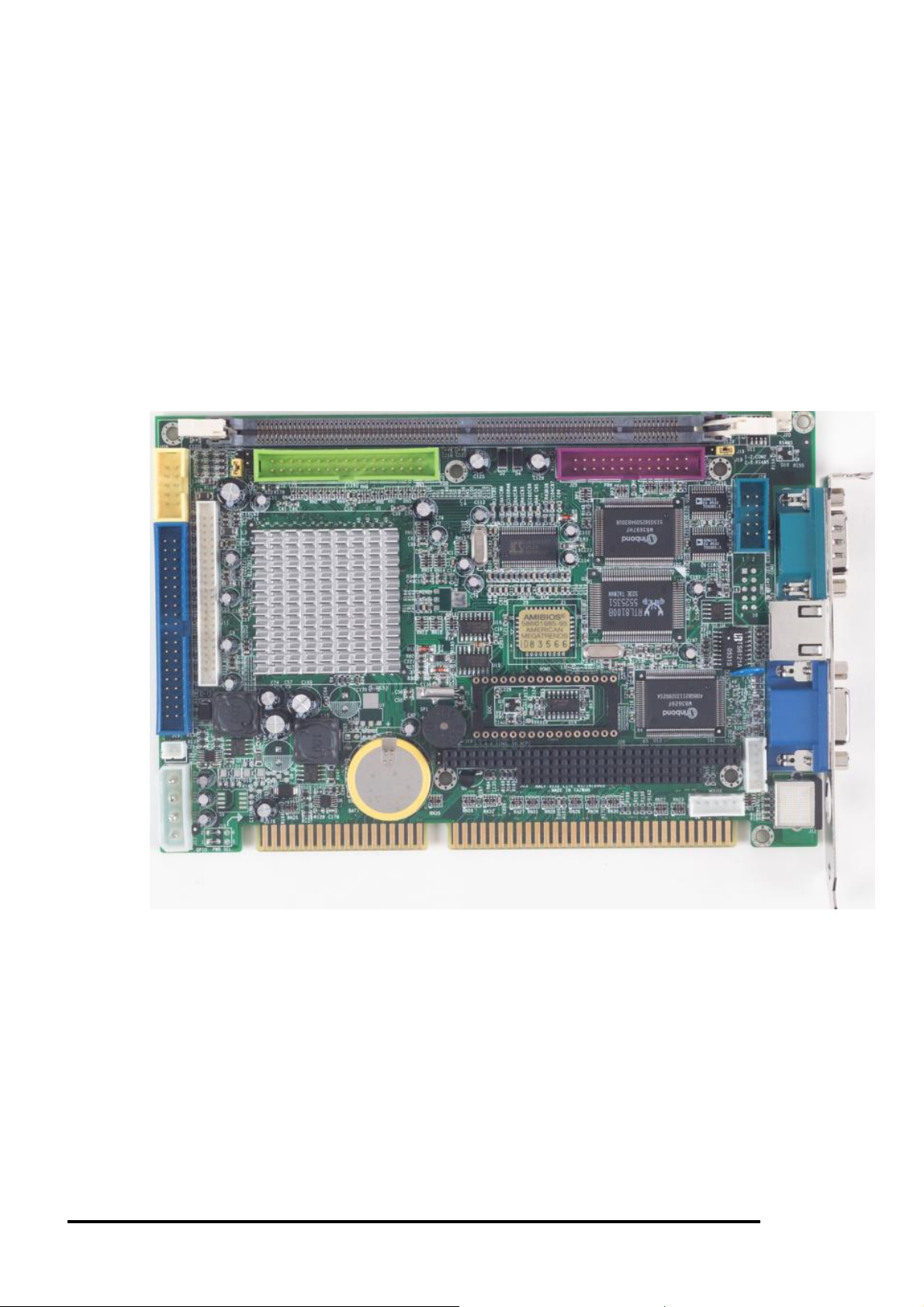
2.1 Board Outline
PCA-6042 : Embedded Half-Size SBC 8
Page 13
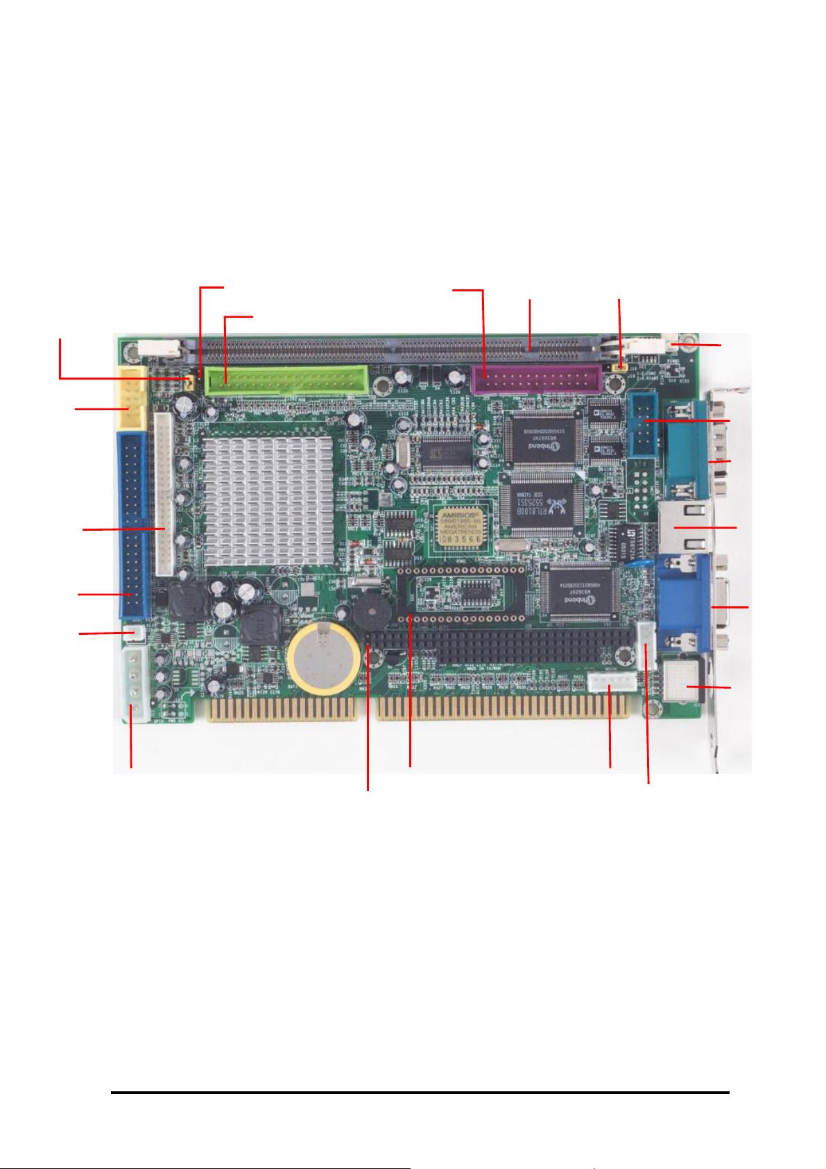
2.2 Connectors & Jumpers Location
J10:LC
D VOL SEL
J14: IDE LED DIMM1 J25: PRN J19: RS485/232 SEL
J21: FDD
J20: RS485
J6: USB
J11: LCD
J15: IDE
J17: PWR-IN
J5: RESET
J24: COM2
J22: COM1
J13. LAN
J1: VGA
J12:PS/2
J9: MOUSE ROM1: DOC
J8: KB
PCA-6042 : Embedded Half-Size SBC 9
Page 14

2.3 Board Dimension
PCA-6042 : Embedded Half-Size SBC 10
Page 15

2.4 Connectors & Jumpers Summary
Summary Table
Nbr Description Type of Connections Pin nbrs.
J1: VGA Connector D-Sub Connector 15-pin
J5: RESET Pin Header 2-pin
J6: USB Box Header, 5x2 10-pin
J8: PS/2 Keyboard
J9: PS/2 Mouse
J10: LCD Volts Sel. Pin Header 3-pin
J11: LCD Connector
J12: PS/2 Keyboard & Mouse Mini-Din Connector 6-pin
J13: 10/100Base-T Ethernet LAN RJ45 Connector 12-pin
J14: IDE LED Pin Header 2-pin
J15: IDE Connector Box Header, 20x2 40-pin
J17: Power Connector
J19: RS232/RS485 Select Pin Header 3-pin
J20: RS485
J21: FDD Connector Box Header, 17x2 34-pin
J22 COM1 D-Sub Connector 9-pin
J24: COM2 Box Header, 5x2 10-pin
J25: Printer Connector Box Header, 13x2 26-pin
J30: FAN Connector Pin Header 2-pin
ROM1 DOC Connector (DiskOnChip) DIP Socket, Grid hole 32-pin
Box Header, 2.0∅ Molex
Box Header, 2.0∅ Molex
Box Header, 2.0∅ , 22x2
Box Header, 5.0∅ Molex
Pin Header, 2.54∅ Molex
5-pin
5-pin
44-pin
4-pin
2-pin
PCA-6042 : Embedded Half-Size SBC 11
Page 16

2.5 Pin Assignments & Jumper Settings
J1 :VGA Connector – 15-pin D-Sub Connector (female)
Pin #
1 MR 6 GND 11 NC
2 MG 7 GND 12 VCC
3 MB 8 GND 13 HYSYNC
4 NC 9 NC 14 VSYNC
5 GND 10 GND 15 VCC
Signal
Name
Pin #
J5: RESET- 2-pin Header
Pin # Status
1-2 Close RESET
J6: USB Connector - 10-pin Box Header
Signal
Name
Pin #
Signal
Name
Pin #
1 VCC 2 VCC
3 -DATA1 4 -DATA0
5 +DATA1 6 +DATA0
7 GND 8 GND
9 GND 10 GND
Signal
Name
J8 : PS/2 Keyboard - 5-pin Header
Pin # Signal Name
1 KBCLK
2 KBDAT
3 NC
4 GND
5 +5V (VCC)
Pin #
Signal
Name
PCA-6042 : Embedded Half-Size SBC 12
Page 17

J9 : PS/2 Mouse - 5-pin Header
G4
G5
G6
G7
G2
G3
Pin # Signal Name
1 PMCLK
2 PMDAT
3 NC
4 GND
5 + 5V (VCC)
J10: LCD Volts Sel. - 3-pin Header
Pin #
Signal
Name
1 VCC
2 LCDVCC
3 3.3V
J11: LCD Connector - 2.0 ∅ pitch 44-pin Box Header
Pin #
1 LCDVCC
3 VAD0 4 VAD1 VAD1 LD1 G3
5 VAD2 6 VAD3 VAD2 LD2 G4
7 VAD4 8 VAD5 VAD3 LD3 G5
9 VAD6 10 VAD7 VAD4 LD4 R0
11 VAD8 12 VAD9 VAD5 LD5 R1
13 VAD10 14 VAD11 VAD6 LD6 R0 R2
15 GND 16 UD4 VAD7 LD7 R1 R3
17 UD5 18 UD6 VAD8 UD0 R2 R4
19 UD7 20 GND VAD9 UD1 R3 R5
21 VBD0 22 VBD1 VAD10 UD2 R4 R6
23 VBD2 24 VBD3 VAD11 UD3 R5 R7
25 VBD4 26 VBD5
27 VBD6 28 VBD7
29 VBD8 30 VBD9
31 VBD10 32 VBD11
33 GND 34 GND VBD3 B1 B3
35 PLDXCLK
37 VADE 38 VBDE VBD5 B3 B5
39 AHSYNC
41 AVSYNC
43 DISPOFF
VBD11 G1
Signal
Name
Pin #
2 LCDVCC
36 VBGCLK
40 VBHSYNC
42 VBVSYNC
44 VDDEN
Signal
Name
SISSED
CONN.
VAD0 LD0 G2
VBD0 B0
VBD1 B1
VBD2 B0 B2
VBD4 B2 B4
VBD6 B4 B6
VBD7 B5 B7
VBD8 G0
VBD9 G1
VBD10
DSTN
DIGIT AL
18-BIT
G0
RGB
24-BIT
PCA-6042 : Embedded Half-Size SBC 13
Page 18

VBDE
UD7 UD7
UD4 UD4
UD5 UD5
UD6 UD6
VADE
PLDXCLK SHFCLK
MOD/LDE
VAHSYNC LP/HYSNC
VHVSYNC
DISOFF ENBT
VBGCLK
VBHSYNC
VBVSYNC
VDDEN VDDEN VDDEN VDDEN
FLM/VYSNC
XCLK XCLK
DEN DEN
HSYNC HSYNC
VSYNC VSYNC
J12 : PS/2 Keyboard & Mouse - 6-pin Mini Din Connector
Pin # Signal Name
1 KBCLK
2 PMCLK
3 GND
4 KBDAT
J13 : 10/100Base-T Ethernet LAN – 12-pin RJ45 Connector
Pin #
10 PLED0 12 PLED1
5 PMDAT
6 + 5V (VCC)
Signal
Signal
Pin #
Name
Name
1 TD+ 2 TD3 R0+ 4 NC
5 NC 6 R07 NC 8 NC
9 VCC 10 VCC
PCA-6042 : Embedded Half-Size SBC 14
Page 19

J14: IDE LED - 2-pin Header
Pin #
1 VCC
2 DASP
Signal
Name
J15: IDE Connector - 40-pin Box Header
Pin #
1 IDERST3 IDED7
5 IDED6
7 IDED5
9 IDED4
11 IDED3
13 IDED2
15 IDED1
17 IDED0
19 GND 20 NC
21 IDEREQ
23 IDEIOW25 IDEIOR27 ICHRDY
29 IDACK31 IDEIRQ
33 IDESA1
35 IDESA0
37 IDECS-0
39 DASP
Signal
Pin #
Name
2 GND
4 IDED8
6 IDED9
8 IDED10
10 IDED11
12 IDED12
14 IDED13
16 IDED14
18 IDED15
22 GND
24 GND
26 GND
28 GND
30 GND
32 NC
34 CBLID
36 IDESA2
38 IDECS-1
40 GND
Signal
Name
J17: Power Connector – 4-pin H eader (P4 Molex 5mm)
Pin #
1 +5V
2 GND
3 GND
4 +12V
Signal
Name
PCA-6042 : Embedded Half-Size SBC 15
Page 20

J19: RS232/RS485 Select - 3-pin Header
Pin # Signal Name
1-2 COM2 / RS232
2-3 RS485
J20: RS485 - 2.54 ∅, 2-pin Mole x Header
Pin # Signal Name
1 RS485+
2 RS485-
J21 : FDD Connector - 34-pin Box Header (17x2)
Pin #
Name
Pin #
1 GND 2 DENSEL
3 GND 4 NC
5 GND 6 NC
7 GND 8 INDEX\
9 GND 10 MTRO\
Signal
11 GND
13 GND
15 GND
17 GND
19 GND
21 GND
23 GND
25 GND
27 GND
29 GND
31 GND
33 GND
12
14
16
18
20
22
24
26
28
30
32
34
Signal
Name
DS1\
DS0\
MTR1\
DIR\
STEP\
WD\
WG\
TR0\
WP\
RD\
HDSEL\
DSKCHG\
PCA-6042 : Embedded Half-Size SBC 16
Page 21

J22 : COM1 – 9-pin D-Sub Connector
Pin #
1 DCD1
3 TXD1
5 GND 6 DSR1
7 RTS1
9 RI1 10-11
Signal
Name
J24 : COM2 - 10-pin Box Header
Pin #
1 DCD2
3 TXD2
5 GND 6 DSR2
Signal
Name
7 RTS2
9
RI2
Pin #
Signal
Name
2 RXD1
4 DTR1
8 CTS1
GGND
Signal
Pin #
Name
2 RXD2
4 DTR2
8 CTS2
10 VCC
J25 : Printer Connector - 26-pin Box Header
Pin #
1 STB3 PD1 4 PD2
5 PD3 6 PD4
7 PD5 8 PD6
9 PD7 10 ACK11 BISY 12 PE
13 SLCT
15 ERR- 16 PRINIT17 SLIN19 GND 20 GND
21 GND 22 GND
23 GND 24 GND
25 GND 26 NC
Signal
Pin #
Name
2 PD0
14 AFD18 GND
Signal
Name
PCA-6042 : Embedded Half-Size SBC 17
Page 22
J30: FAN - 2.54 ∅, 2-pin Pin Header
Pin # Signal Name
1 GND
2 +5v
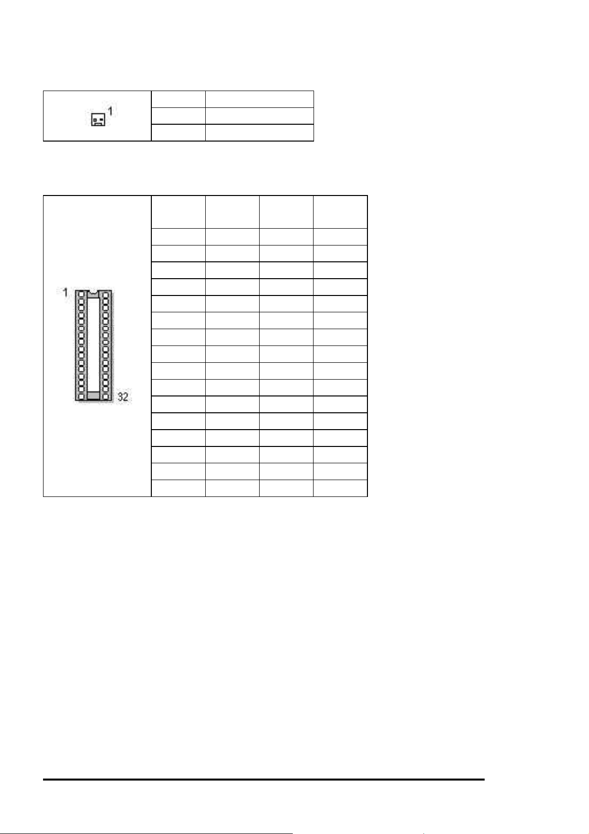
ROM1 : (DiskOnChip) DOC Connector – 32-pin Grid hole DIP Socket
Pin #
1 NC 2 NC
3 NC 4 XA12
5 XA7 6 XA6
7 XA5 8 XA4
9 XA3 10 XA2
11 XA1 12 XA0
13 XD0 14 XD1
15 XD2 16 GND
17 XD3 18 XD4
19 XD5 20 XD6
21 XD7 22 ROMCS1
23 XA1 24 MDRCL
25 XA11 26 XA9
27 XA8 28 NC
29 NC 30 NC
31 MWTCL 32 VCC
Signal
Name
Pin #
Signal
Name
PCA-6042 : Embedded Half-Size SBC 18
Page 23

2.6 DiskOnChip Flash Disk
2.6.1 Setup a DiskO nChip
® 2000 Flash Disk
Installation Instructions
1. Make sure the power of PCA-6042 is turned OFF.
2. Plug the DiskOnChip 2000 device into its socket. Verify the mounting orientation of the
DiskOnChip 2000 is correct (DiskOnChip 2000 pin 1 must be aligned with pin 1 of the
socket).
3. Turn on the power of the system, and you may observe the messages displayed by
the DiskOnChip 2000 when its drivers are automatically loaded into system’s memory.
Start Address is assigned and fixed at “0E0000 HEX”.
4. If the DiskOnChip 2000 is the only disk in the system, it will appear as the first disk
(drive C: in DOS).
5. If there are more disks besides the DiskOnChip 2000, the DiskOnChip 2000 will
appear by default as the last drive.
6. If you want the DiskOnChip 2000 to be bootable: a - copy the operating sys tem files
into the DiskOnChip by using the standard DOS command (for example: sys d:) b The DiskOnChip should be the only disk in the systems or should be configured as the
first disk in the system (c: ) using the DUPDATE utility
For more information on DiskOnChip2000 technology, visit M-Systems Web site –
http:// www.m-sys.com
where you can find Utilities Manual, Data Sheets and Application
Notes. In addition, you can find the lasted DiskOnChip 2000 S/W Utilities.
PCA-6042 : Embedded Half-Size SBC 19
Page 24

2.7 Watchdog Timer
The watchdog timer work flow of Vo rtex86 is: If the watchdog timer expires the first time,
the expired event will set SFTMR0_STS and timer will reload its inital value and count
again. If the timer expire the second time, the expired event will set SFTMR1_STS.
Software Watchdog Timer Initial Value: Default Value: FFh
I/O
Address
84Ah 7:0 R/W Software Watchdog Timer Initial Value
Bit Access Description
Writing to this register will reload the software watchdog
timer with the value specified in this register. If the software
watchdog timer expires the first time, the expired event will
set the SFTMR0_STS and the timer will reload its initial
value and count again. If the timer expire the second time,
the expired event will set the SFTMR1_STS. The timer
value can't be read from this field.
Software Watchdog Timer Control Register: Default Value: 00h
I/O
Address
84Bh
Bit Access Description
7 R/W Software Watchdog Timer Counting Enable
The software watchdog timer will start to count when this bit
is set to one.
6 RO Reserved
5:4 R/W Software Watchdog Timer Clock Select
00 : 4 ms
01 : 1 second
10 : 1 minute
11 : 1 hour
3:2 R/W Software Watchdog Timer Expiration Event 1 Routing Select
When SFTMR1_STS is set to one, an
SMI#/SFTIRQ/PCIRST# will be generated according to the
following combination.
00 : No effect
01 : SMI#
10 : SFTIRQ
11 : PCIRST#
PCA-6042 : Embedded Half-Size SBC 20
Page 25

1:0 R/W Software Watchdog Timer Expiration Event 0 Routing Select
When SFTMR0_STS is set to one, an
SMI#/SFTIRQ/PCIRST# will be generated according to the
following combination.
00 : No effect
01 : SMI#
10 : SFTIRQ
11 : PCIRST#
Legacy Event Status Register: Default Value: 00h
I/O
Address
841h
Bit Access Description
7 R/WC Software Watch Dog Timer Event 1 Status (SFTMR1_STS)
This bit is set when the software watchdog timer expires the
second time. This status bit does not have its corresponding
enable bit and can survive under PCIRST#.
6 R/WC Software Watch Dog Timer Event 0 Status (SFTMR0_STS)
This bit is set when the software watchdog timer expires the
second time. This status bit does not have its corresponding
enable bit and can survive under PCIRST#.
C Example
Those C code for DOS will show you more: (Download C source code for
DOS and execute file)
#include <conio.h>
#include <stdio.h>
#include <time.h>
void main()
{
clock_t clk;
int nTime = 5;
/* set time out */
outp(0x84a, nTime);
/* set timer clock to 1 second and "Timer Expiration Event 0/1" to reset system.
*/
outp(0x84b, 0x9c);
PCA-6042 : Embedded Half-Size SBC 21
Page 26

printf("Press any key to stop clearing watchdog timer status...\n");
while(!kbhit())
{
/* clear "Timer Expiration Event 0/1" bit */
outp(0x841, 0xc0);
}
getch();
printf("System will be reset after %d seconds.\n", nTime * 4);
clk = clock();
while(!kbhit())
printf("%2.2f\r", (clock() - clk) / CLK_TCK);
}
Assembler Example code
mov dx,84ah ; set timeout = 20 second
mov al,5
out dx,al
mov dx,84bh ; set timer clock to 1 second and "Timer Expiration Event 0/1" to
reset system.
mov al,9ch
out dx,al
; clearing watchdog timer status
mov dx,841h
mov al,0c0h
out dx,al
PCA-6042 : Embedded Half-Size SBC 22
Page 27

C h a p t e r 3
SVGA Setup
3.1 Introduction
The PCA-6042 offers high performance/low cost Vortex™ SoC (System on Chip) solution
that. integrates a x86 compatible processor, high performance North Bridge, advanced
hardware GUI engine and Super-South bridge into a single chipset – this SoC design
supports the now PC technology, USB, Legacy Removal, CIR, Memory Stick, Smart Card
and Slotless Design for a variety of IA (Information Appliance) applications. It also has a
built-in VGA controller.
3.1.1 SoC Chipset
The embedded video uses the integrated Ultra-AGP™ VGA controller for Hardware
2D/video/Graphics Accelerators, this board supports conventional analog CRT monitor or
flat panel. It is both AGP 4X / Fully DirectX 8 Compliant. It also provides Monitor /
Secondary CRT Monitor output. This video SVGA controller supports conventional analog
CRT monitor or flat panel. In addition, it also supports interlaced a nd non-interlac ed analog
monitors (color and monochrome VGA) in high-resolution modes while maintaining
complete IBM VGA compatibility. Multiple freque ncy (multi-sync) monito rs are handled as if
they were analog monitors.
3.1.2 Display memory
The VGA controller can drive CRT displays or color panel displays with resolutions up to
1920 x 1440 at 256 colors (True colors). It supports Shared System Memory up to 128
MB.
PCA-6042 : Embedded Half-Size SBC 23
Page 28
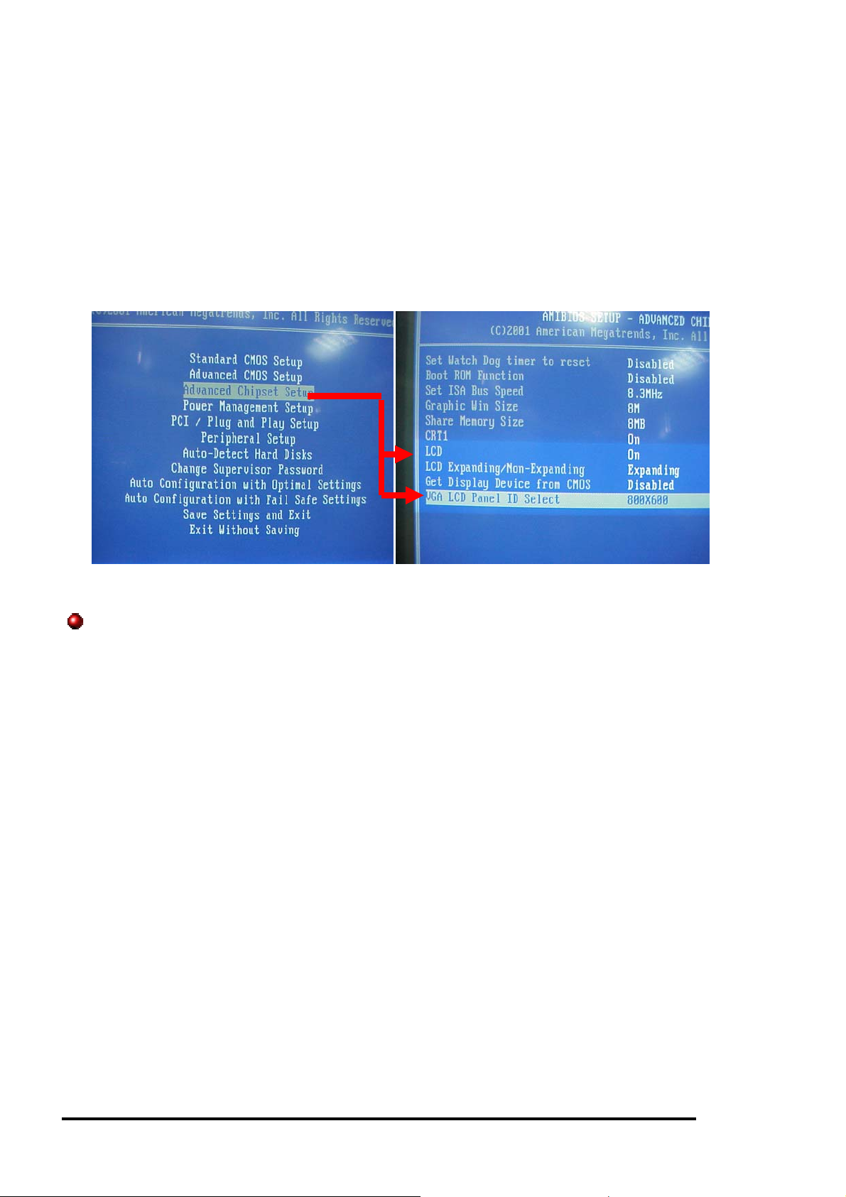
3.2 Flat Panel BIOS Setting
The VORTEX86-6042 offers the option in the BIOS Setting to ON/OFF the LCD Fl at Panel.
Before you connect the LCD Flat Panel to CPU Board, please go to BIOS Æ Advanced
Chipset Setup, to turn “ON” the “LCD”, and select the corresponding resolution on “ VGA
LCD Panel ID Select”.
Supporte d Fl at Pa ne l s:
- PVI 6.4” TFT LCD panel P/N: V16C6448AC
- SHARP 6.4” TFT LCD panel P/N: LQ64D341 (HIROSE DF9BA-31P-1V)
- NEC 6.5” TFT Color LCD panel P/N: NL6448BC20-08 (HIROSE DF9B-31P-1V)
For more Flat Panels information, please contact your regional sales.
3.3 Flat Panel Wiring
Before you connect the LCD Flat Panel with PCA-6042, please make the your LCD
Flat Panel is 3.3V or 5V, then place the J10 (J10, see page 13) on the correct position.
For the Wiring, please refer to page 13, J11 , LCD connector. Or email support@emacinc.com
if you have any question.
PCA-6042 : Embedded Half-Size SBC 24
Page 29

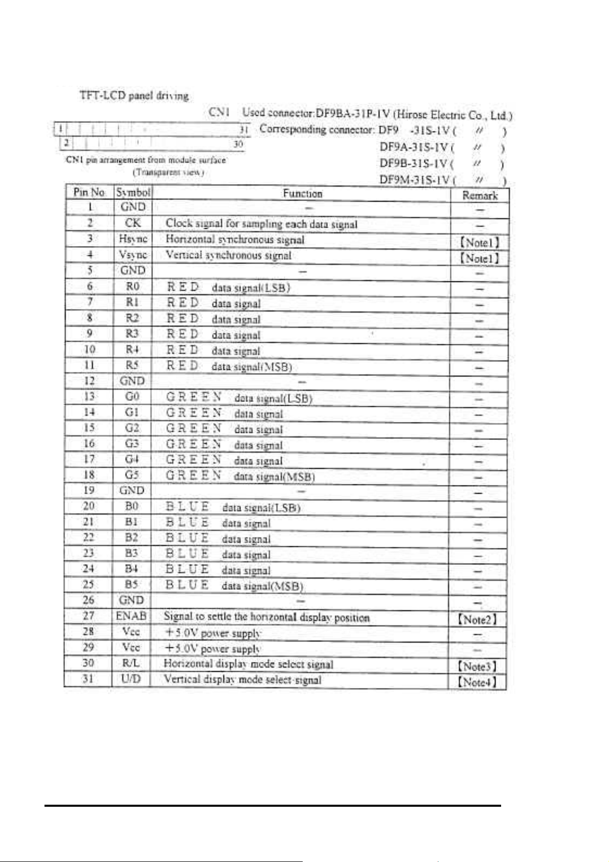
- PVI 6.4” TFT LCD panel P/N: V16C6448AC
TFT-LCD Panel Driving
Note: The TFT-LCD panel display is compatible with four kinds of timing. They are
VGA-480, VGA-400, VGA-350 and freedom mode. The polarization of Hsync and
Vsync determine the timings.
PCA-6042 : Embedded Half-Size SBC 25
Page 30
- SHARP 6.4” TFT LCD panel P/N: LQ64D341 (HIROSE DF9BA-31P-1V)
PCA-6042 : Embedded Half-Size SBC 26
Page 31

- NEC 6.5” TFT Color LCD panel P/N: NL6448BC20-08 (HIROSE DF9B-31P-1V)
PCA-6042 : Embedded Half-Size SBC 27
Page 32

C h a p t e r 4
Network Interface
4.1 Introduction
The Realtek RTL-8100B 10/100Mbps Ethernet controller board supports both
10/100BASE-T and Coax 10Base-2 ‘BNC’ connectors, and allows direct connection to your
10/100Mbps Ethernet based Local Area Network for full interaction with local servers, wide
area networks such as the Internet.
I/O and IRQ settings can be done by software with the supplied utility software, or it can be
set for Plug and Play compatibility. The controller supports : Full- Duplex Ethernet function
to double channel bandwidth, auto media detection.
4.2 Software Support
On-board EEPROM (93C46) programming
Setup/Diagnostic program for DOS
Help utility for easy installation
RPL boot ROM for Novell Netware, Microsoft NT
NDIS2 (DOS,OS/2,Lantastic,WFW3.1¡K¡K)
NDIS3,NDIS4,NDIS5 for WIN95,98,NT3.51,4.0,5.0,WFW3.11
Netware 16-bit ODI driver for DOS,OS/2 and 32-bit ODI driver for Netware
3.x,4.x,5.0 Server
Packet driver for UNIX Client
SCO Unix driver
Linux driver
Board Support Package for Windows CE.NET 4.2 , Windows CE 5.0
All operating systems that support standard NE2000
PCA-6042 : Embedded Half-Size SBC 28
Page 33

Warranty
This product is warranted to be in good working order for a period of one year from the date of
purchase. Should this product fail to be in good working order at any time during this period, we will,
at our option, replace or repair it at no additional charge except as set forth in th e following terms.
This warranty does not app ly to products damaged by misuse, modifications, accident or disaster.
Vendor assumes no liability for any damages, lost profits, lost savings or any other incidental or
consequential damage resul ting from the use, misuse of, originality to use this product. Vendor will
not be liable for any claim made by any other related party. Return authorization must be obtained
from the vendor before returned merchandise will be accepted. Authorization can be obtained by
calling or faxing the vendor and requesting a Return Merchandise Authorization (RMA) number.
Returned goods should always be accompanied by a clear problem description.
PCA-6042 : Embedded Half-Size SBC 29
 Loading...