

Page 1

IPPC-9151 Series
Rugged Industrial Panel PC with
Intel® Pentium® 4 or Celeron®
and 15" LCD Display
Users Manual
Page 2

Copyright notice
This document is copyrighted 2005, by Advantech Co. Ltd. All rights are
reserved. Advantech Co., Ltd. reserves the right to alter the products
described in this manual at any time without notice. No part of this manual may be reproduced, copied, translated or transmitted in any form or
by any means without the prior written permission of Advantech. Information provided in this manual is intended to be accurate and reliable.
However, Advantech assumes no responsibility for use of this manual,
nor for any infringements upon the rights of third parties which may
result from such use. All brand and product names mentioned herein are
trademarks or registered trademarks of their respective holders.
Acknowledgments
IBM and PC are trademarks of International Business Machines Corporation.
For more information on this and other Advantech products, please visit
our website at: http://www.advantech.com
For technical support and service, please visit our support website at:
http://www.advantech.com.tw/support/
Part No. 2003915101
Edition 1.3
June 2007
IPPC-9151 Series Users Manual ii
Page 3

FCC Class A
Note: This equipment has been tested and found to comply with the limits
for a Class A digital device, pursuant to part 15 of the FCC Rules. These
limits are designed to provide reasonable protection against harmful
interference when the equipment is operated in a commercial environment. This equipment generates, uses, and can radiate radio frequency
energy and, if not installed and used in accordance with the instruction
manual, may cause harmful interference to radio communications. Operation of this equipment in a residential area is likely to cause harmful interference in which case the user will be required to correct the interference
at his own expense.
Warning! Any changes or modifications made to the
equipment which are not expressly approved by
the relevant standards authority could void your
authority to operate the equipment.
iii
Page 4

Packing List
Before setting up the system, check that the item is among those listed
below and is in good condition. If your Panel PC does not match any of
those below, please contact your dealer immediately.
1 x IPPC-9151 Panel PC
1 x Accessory pack, with:
• DESKTOP BRACKET(L)
• DESKTOP BRACKET(R)
• FIX Bracket x 4
• COMPRESSION SPRING x 4
• THERMAL GREASE
• Registration and 1 year Warranty card
• CD ROM for IPPC Series DRV
• Urethane Seal (UP/DOWN)
• Urethane Seal (L/R)
• Screw Bag
S/S D=5 H=1 + M3*5L ST Ni x 6
1/4R/S D=8.1 H=2.2 + #6-32*3/16"L ST Ni x 6
1/4R/S D=6.6 H=1.5 + M3*5L ST Ni x 8
ROUND M6*25 x 4
SP/S D=8 H=1.5 - M4*6L ST Ni x 8
The IPPC-9151 Series of Industrial Panel PCs includes the following
models:
IPPC-9151G-XAE
Rugged Pentium 4 Industrial Panel PC with 15" LCD,180W AC power
supply, Stainless steel chassis and aluminum front panel
IPPC-9151G-RAE
IPPC-9151G-XAE with resistive touchscreen
IPPC-9151 Series Users Manual iv
Page 5

IPPC-9151F-XAE
Rugged Pentium 4 Industrial Panel PC with 15" LCD,180W AC power
supply, Stainless steel chassis and flat-sealed aluminum front panel
IPPC-9151F-RAE
IPPC-9151F-XAE with resistive touchscreen
Additional Information and Assistance
Step 1. Visit the Advantech web site at www.advantech.com where you
can find the latest information about the product.
Step 2. Contact your distributor, sales representative, or Advantech's
customer service center for technical support if you need additional assistance. Please have the following information ready
before you call:
• Product name and serial number
• Description of your peripheral attachments
• Description of your software (operating system, version, application
software, etc.)
• A complete description of the problem
• The exact wording of any error messages
v
Page 6

Sa fety I ns tr uc ti ons
1. Read these safety instructions carefully.
2. Keep this User's Manual for later reference.
3. Disconnect this equipment from any AC outlet before cleaning. Use a damp
cloth. Do not use liquid or spray detergents for cleaning.
4. For plug-in equipment, the power outlet socket must be located near the
equipment and must be easily accessible.
5. Keep this equipment away from humidity.
6. Put this equipment on a reliable surface during installation. Dropping it or let-
ting it fall may cause damage.
7. The openings on the enclosure are for air convection. Protect the equipment
from overheating. DO NOT COVER THE OPENINGS.
8. Make sure the voltage of the power source is correct before connecting the
equipment to the power outlet.
9. Position the power cord so that people cannot step on it. Do not place anything
over the power cord.
10. All cautions and warnings on the equipment should be noted.
11. If the equipment is not used for a long time, disconnect it from the power
source to avoid damage by transient overvoltage.
12. Never pour any liquid into an opening. This may cause fire or electrical shock.
13. Never open the equipment. For safety reasons, the equipment should be
opened only by qualified service personnel.
14. If one of the following situations arises, get the equipment checked by service
personnel:
a. The power cord or plug is damaged.
b. Liquid has penetrated into the equipment.
c. The equipment has been exposed to moisture.
d. The equipment does not work well, or you cannot get it to work according
to the user's manual.
e. The equipment has been dropped and damaged.
f. The equipment has obvious signs of breakage.
15. DO NOT LEAVE THIS EQUIPMENT IN AN ENVIRONMENT WHERE
THE STORAGE TEMPERATURE MAY GO BELOW -20° C (-4° F) OR
ABOVE 60° C (140° F). THIS COULD DAMAGE THE EQUIPMENT. THE
EQUIPMENT SHOULD BE IN A CONTROLLED ENVIRONMENT.
16. CAUTION: DANGER OF EXPLOSION IF BATTERY IS INCORRECTLY
REPLACED. REPLACE ONLY WITH THE SAME OR EQUIVALENT
TYPE RECOMMENDED BY THE MANUFACTURER, DISCARD USED
BATTERIES ACCORDING TO THE MANUFACTURER'S INSTRUCTIONS.
The sound pressure level at the operator's position according to IEC 704-1:1982 is
no more than 70 dB (A).
DISCLAIMER: This set of instructions is given according to IEC 704-1. Advantech disclaims all responsibility for the accuracy of any statements contained
herein.
IPPC-9151 Series Users Manual vi
Page 7

W ic ht i ge Si c he rh e is hi n we is e
1. Bitte lesen sie Sich diese Hinweise sorgfältig durch.
2. Heben Sie diese Anleitung für den späteren Gebrauch auf.
3. Vor jedem Reinigen ist das Gerät vom Stromnetz zu trennen. Verwenden Sie
Keine Flüssig-oder Aerosolreiniger. Am besten dient ein angefeuchtetes Tuch
zur Reinigung.
4. Die NetzanschluBsteckdose soll nahe dem Gerät angebracht und leicht
zugänglich sein.
5. Das Gerät ist vor Feuchtigkeit zu schützen.
6. Bei der Aufstellung des Gerätes ist auf sicheren Stand zu achten. Ein Kippen
oder Fallen könnte Verletzungen hervorrufen.
7. Die Belüftungsöffnungen dienen zur Luftzirkulation die das Gerät vor überhitzung schützt. Sorgen Sie dafür, daB diese Öffnungen nicht abgedeckt werden.
8. Beachten Sie beim. AnschluB an das Stromnetz die AnschluBwerte.
9. Verlegen Sie die NetzanschluBleitung so, daB niemand darüber fallen kann.
Es sollte auch nichts auf der Leitung abgestellt werden.
10. Alle Hinweise und Warnungen die sich am Geräten befinden sind zu
beachten.
11. Wird das Gerät über einen längeren Zeitraum nicht benutzt, sollten Sie es vom
Stromnetz trennen. Somit wird im Falle einer Überspannung eine Beschädigung vermieden.
12. Durch die Lüftungsöffnungen dürfen niemals Gegenstände oder Flüssigkeiten
in das Gerät gelangen. Dies könnte einen Brand bzw. elektrischen Schlag auslösen.
13. Öffnen Sie niemals das Gerät. Das Gerät darf aus Gründen der elektrischen
Sicherheit nur von authorisiertem Servicepersonal geöffnet werden.
14. Wenn folgende Situationen auftreten ist das Gerät vom Stromnetz zu trennen
und von einer qualifizierten Servicestelle zu überprüfen:
a - Netzkabel oder Netzstecker sind beschädigt.
b - Flüssigkeit ist in das Gerät eingedrungen.
c - Das Gerät war Feuchtigkeit ausgesetzt.
d - Wenn das Gerät nicht der Bedienungsanleitung entsprechend funktioniert
oder Sie mit Hilfe dieser Anleitung keine Verbesserung erzielen.
e - Das Gerät ist gefallen und/oder das Gehäuse ist beschädigt.
f - Wenn das Gerät deutliche Anzeichen eines Defektes aufweist.
15. VOSICHT: Explisionsgefahr bei unsachgemaben Austausch der Batterie.Ersatz nur durch densellben order einem vom Hersteller empfohlenemahnlichen Typ. Entsorgung gebrauchter Batterien navh Angaben des
Herstellers.
16. ACHTUNG: Es besteht die Explosionsgefahr, falls die Batterie auf nicht fachmännische Weise gewechselt wird. Verfangen Sie die Batterie nur gleicher
oder entsprechender Type, wie vom Hersteller empfohlen. Entsorgen Sie Batterien nach Anweisung des Herstellers.
vii
Page 8

Der arbeitsplatzbezogene Schalldruckpegel nach DIN 45 635 Teil 1000
beträgt 70dB(A) oder weiger.
Haftungsausschluss: Die Bedienungsanleitungen wurden entsprechend
der IEC-704-1 erstellt. Advantech lehnt jegliche Verantwortung für die
Richtigkeit der in diesem Zusammenhang getätigten Aussagen ab.
IPPC-9151 Series Users Manual viii
Page 9

Contents
Chapter 1 General Information ........................................2
1.1 Introduction ....................................................................... 2
1.2 Specifications .................................................................... 3
1.2.1 General............................................................................ 3
1.2.2 Standard PC Functions.................................................... 3
1.2.3 AGP SVGA/Flat Panel Interface .................................... 4
1.2.4 Audio Function ............................................................... 4
1.2.5 PCI bus Ethernet Interface.............................................. 5
1.2.6 PCMCIA interface .......................................................... 5
1.2.7 Analog Resistive Touchscreen (optional)....................... 5
1.2.8 Optional Accessories ...................................................... 5
1.2.9 Environmental................................................................. 5
1.3 Dimensions........................................................................ 6
Figure 1.1:IPPC-9151FA Dimensions............................ 6
Figure 1.2:IPPC-9151GA Dimensions ........................... 6
Chapter 2 System Setup.....................................................8
2.1 A Quick Tour of IPPC-9151 ............................................. 8
Figure 2.1:Side View ...................................................... 9
Figure 2.2:Bottom View ................................................. 9
2.1.1 PS/2 Mouse and Keyboard ........................................... 10
2.1.2 Parallel Port................................................................... 10
2.1.3 VGA port ...................................................................... 10
2.1.4 Serial COM ports .......................................................... 11
2.1.5 USB ports...................................................................... 11
2.1.6 Audio Interface ............................................................. 11
2.1.7 Ethernet......................................................................... 12
2.1.8 Adjusting the LCD brightness ...................................... 12
2.1.9 System turn ON/OFF .................................................... 12
2.2 Installing SDRAM.......................................................... 13
2.3 Installing a CPU .............................................................. 15
2.4 Installing a 3.5" HDD...................................................... 16
2.5 Installing Add-on Cards ................................................ 18
2.6 Mounting Instructions .................................................... 18
2.6.1 Panel Mounting............................................................. 18
2.6.2 Rack Mounting ............................................................. 18
Chapter 3 Jumper Settings &
Connectors 20
3.1 Jumpers and Connectors.................................................. 20
3.1.1 Setting jumpers ............................................................. 20
3.1.2 Jumpers and switches.................................................... 21
ix
Page 10

Table 3.1:Jumpers, switches and their functions.......... 21
3.1.3 Jumper Locations .......................................................... 21
Figure 3.1:Jumpers on the IPPC-9151 motherboard .... 21
3.1.4 Connectors .................................................................... 22
Table 3.2:Panel PC connectors ..................................... 22
3.1.5 Locating connectors...................................................... 23
Figure 3.2:Connectors on IPPC-9151 motherboard .....23
3.2 CPU Installation .............................................................. 24
3.3 CMOS Clear for External RTC (JP3) ............................. 24
Table 3.4:CMOS clear (JP3)......................................... 24
3.4 COM-port interface (JP4, JP5)........................................ 25
3.4.1 COM2 RS-232/422/485 setting (JP4)........................... 25
Table 3.5:COM2 RS-232/422/485 setting (JP4)........... 25
Table 3.6:COM 1/2 Pin 9 setting (JP5)......................... 26
3.5 VGA interface ................................................................. 26
3.5.1 LCD panel power setting .............................................. 26
Table 3.7:LCD Panel Power Setting (JP2) ................... 26
Chapter 4 Intel Chipset....................................................28
4.1 Introduction ..................................................................... 28
4.2 Driver Installation ........................................................... 28
4.2.1 Installation for Windows 98/NT/ME/2000/XP............. 29
4.3 Further Information......................................................... 30
Chapter 5 PCI Bus Ethernet Interface...........................32
5.1 Introduction ..................................................................... 32
5.2 Installation of Ethernet Driver......................................... 32
5.2.1 Installation for Windows 98/NT/ME/2000................... 33
5.3 Further Information......................................................... 35
Chapter 6 VGA Setup ......................................................38
6.1 Introduction ..................................................................... 38
6.1.1 Chipset .......................................................................... 38
6.1.2 Display memory............................................................ 38
6.1.3 Display types................................................................. 38
6.2 Installation of the VGA Driver........................................ 39
6.2.1 Installation for Windows 95/98/ME ............................. 39
6.3 Further Information......................................................... 40
Chapter 7 Audio Setup.....................................................42
7.1 Introduction ..................................................................... 42
7.2 Installation of the Audio Driver ...................................... 42
7.2.1 Installation for Windows 98/ME/2000/XP................... 43
Chapter 8 Touchscreen ................................................... 46
8.1 Introduction ..................................................................... 46
8.2 Touchscreen Specifications............................................. 46
IPPC-9151 Series Users Manual x
Page 11

8.3 Installing Driver for Windows 2000/XP ......................... 47
8.4 Configuring PenMount Windows 2000/XP Driver......... 52
8.4.1 PenMount Control Panel ............................................. 52
8.4.2 PenMount Monitor Menu Icon .................................... 62
8.4.3 PenMount Rotating Functions ..................................... 63
8.5 Uninstall the PenMount Windows 2000/XP driver......... 64
Chapter 9 PCMCIA .........................................................66
9.1 Introduction ..................................................................... 66
9.2 Installation of PCMCIA Driver....................................... 66
9.2.1 Installation for Windows .............................................. 67
Chapter 10 Award BIOS Setup.........................................70
10.1 Award BIOS Setup.......................................................... 70
10.2 CMOS Setup Utility ........................................................ 70
10.2.1 Standard CMOS Setup.................................................. 71
Figure 10.1:Standard CMOS features........................... 71
Figure 10.2:Standard CMOS features........................... 72
10.3 Advanced BIOS Features................................................ 74
10.4 Advanced Chipset Features............................................. 78
10.5 Integrated Peripherals...................................................... 81
10.6 Power Management Setup............................................... 85
10.7 PnP/PCI Configuration.................................................... 89
10.8 PC Health Status.............................................................. 91
10.9 Frequency/Voltage Control............................................. 92
10.10 Load Optimized Defaults ................................................ 92
10.11 Set Password ................................................................... 93
10.12 Save & Exit Setup ........................................................... 94
10.13 Exit Without Saving........................................................ 94
Appendix A LCD Specifications.........................................96
Appendix B Pin Assignments .............................................98
B.1 ATX Power connector 1 (CN1) .................................... 98
Table B.1:AT Power connector 1 (CN1)...................... 98
B.2 ATX power connector 2 (CN2)....................................... 99
Table B.2:ATX power connector 2 (CN2) ...................99
B.3 LVDS connector 1(CN4) ................................................ 99
Table B.3:LVDS connector 1(CN4) ............................. 99
B.4 LVDS connector 2(CN6) .............................................. 100
Table B.4:Table B.4: LVDS connector 2 (CN6) ........ 100
B.5 Inverter power connector (CN5) ................................... 100
Table B.5:Inverter power connector (CN5)................ 100
B.6 FDD connector (CN9)................................................... 101
Table B.6:FDD connector (CN9)................................ 101
B.7 Internal speaker connector (CN15) ............................... 102
xi
Page 12

Table B.7:Internal speaker connector (CN15)............ 102
B.8 IR connector (CN24)..................................................... 102
Table B.8:IR connector (CN24).................................. 102
B.9 Fan power connector (FAN1 & FAN2) ........................ 102
IPPC-9151 Series Users Manual xii
Page 13

CHAPTER
General Information
This chapter gives background
information on the IPPC-9151 series
Sections include:
• Introduction
• Specifications
• Dimensions
1
Page 14

Chapter 1 General Information
1.1 Introduction
The IPPC-9151 seriesof industrial panel PCs is especially designed to fit
in space-limited environments where expansion is restricted. Its solid
structure enables systems to operate under harsh industrial conditions.
Sturdy structure
The whole system is protected by a firm solid structure. The front panel is
made of sturdy aluminum and has strengthened glass. It is shock resistant,
and complies with NEMA4/IP65. The stainless steel case (SUS304) on
the rear side is rugged and corrosion resistant, and enables the system to
operate reliably in even the harshest of environments.
Easy maintenance
A back door with lock is located right above the motherboard. Thus users
can easily maintain the CPU, HDD, SDRAM and CD-ROM drive. Jumpers can be easily set without removing a single screw. The lock protects
the system from intruders.
Economical
The PCM-9683 motherboard has Socket 478 architecture. It supports
Pentium 4 up to 2.8 GHz and Celeron up to 2.4 GHz. Socket 478 is an
economical yet powerful system. Its reliability enables the system to
operate faultlessly in industrial environments.
Friendly HMI
Systems in the IPPC-9151 series are equipped with a 15" LCD screen,
which provides high resolution display quality. The result is vivid, bright,
and sharp quality images. The panel PC is perfectly suited for Windows
OS. The touschscreen version enables simple operation, making the Panel
PC a solid industrial digital controller interface. In addtion, the rugged
design of the IPPC-9151 series offers 3 front panel options with aluminum/stainless/flat-seal for various requirements.
IPPC-9151 Series Users Manual 2
Page 15

1.2 Specifications
1.2.1 General
• Dimensions (W x H x D):
Front Panel: 428 x 310 x 8 mm (16.85" x 12.2" x 0.31")
Cabinet: 402 x 290 x 162 mm (15.82" x 11.41"x 6.37")
Cut out dimension: 406 x 294 mm (15.98" x 11.57")
• Weight: 13 kg (28 lb)
• Power supply: 180 W
• Input voltage: 100 V AC ~ 240 V AC @ 50 ~ 60 Hz, 2A
• Output voltage: +5 V @ 15 A, +12 V @ 5 A, -12V @ 0.5A
• Disk drive housing:
Supports one 3.5" HDD, one slim size CD-ROM and FDD drive.
• Chassis:
Aluminum front frame complies with NEMA4/IP65. SUS304 stainless
steel back case
1.2.2 Standard PC Functions
• CPU:
Socket 478 Pentium 4 up to 2.8 GHz.
Celeron up to 2.4 GHz
• BIOS: Award 4 MB Flash BIOS, supports Plug & Play, APCI
• Chipset: Intel 845GV / ICH4
• 2nd level cache: On-die 256 or 512 KB
• RAM:
Two 184-pin DDR DIMM sockets up to 2GB DDR SDRAM
• PCI bus master IDE interface:
Supports two connectors. Each connector has one channel and supports
two IDE devices. Each channel supports PIO modes 0 ~ 4, DMA
modes 0 ~ 2, and Ultra DMA 33 simultaneously. The secondary connector is designated for the CD-ROM drive. BIOS supports IDE CDROM boot-up.
• Parallel port:
One parallel port, supports SPP/EPP/ECP parallel mode.BIOS configurable to LPT1, LPT2, LPT3 or disabled
3 Chapter 1
Page 16

• Serial ports:
Two serial ports with one RS-232 port (COM1) and one RS-232/422/
485 port (COM2). Both ports are compatible with 16C550 UARTs
• Universal serial bus (USB) port: Supports up to 4 USB (version 2.0)
ports.
• PCI bus expansion slots:
Two expansion slots for two PCI cards.
• Watchdog timer:
62-level, interval 1 ~ 62 seconds. Automatically generates system reset
or IRQ11 when the system stops due to a program error or EMI.
Jumperless selection and software enabled/disabled
• Battery: 3.0 V @ 195 mA lithium battery
1.2.3 AGP SVGA/Flat Panel Interface
• Chipset: Intel 845GV chipset with integrated Intel Extreme Graphics 2
for 2D/3D video accelerator
• Display memory: 8 MB share main memory
• Display type:
Simultaneously supports CRT and flat panel displays (TFT)
• Display resolution:
Supports LCD displays up to 1024 x 768 @ 262K in colors
1.2.4 Audio Function
• Chipset: Integrated in Intel 845GV ICH4 South Bridge
• Audio controller:
AC97 Ver.2.0 compliant interface, Multi stream, Direct sound and
Direct Sound 3D acceleration
• Stereo sound:
18-bit full-duplex codec
• Audio interface:
Microphone-in, line-in, line-out, and game ports MPU-401.
IPPC-9151 Series Users Manual 4
Page 17

1.2.5 PCI bus Ethernet Interface
• Chipset: Intel RC82540Em local bus.
• Ethernet Interface:
Fully complies with IEEE 802.3u 100Base-T and 10 Base-T specifications. Includes software drivers and boot ROM
• 100/10Base-T auto-sensing capability
1.2.6 PCMCIA interface
• Chipset: RICOH R5C554
• Cardbus controller: A PC card controller offers a single chip solution as
a bridge between the PCI bus and the Cardbus
1.2.7 Analog Resistive Touchscreen (optional)
• Type: Analog resistive
• Resolution: 1024 x 1024
• Light Transmission:
75% (Gouge Hardness is greater than 4H per ASTM D3363-92 for
HCC01, HCG10 and HCG12)
• Controller: RS-232 interface
• Power Consumption: +5 V @ 200 mA
• Software Driver:
Supports DOS, Windows 3.1, Windows 98/ME/2000/XP and Windows NT 4.0
1.2.8 Optional Accessories
• IPPC-9151G-RMKE
19" rack mounting kit for IPPC-9151 series.
1.2.9 Environmental
• Operating temperature: 0 ~ 50° C (32 ~ 122° F)
• Storage temperature: -20 ~ 60° C (-4 ~ 140° F)
• Relative humidity: 10 ~ 90% @ 40° C (non-condensing)
• Shock: 30 G peak acceleration (11 ms duration)
• Power MTBF: 100,000 hrs
• Certifications: CE, CCC, FCC Class, UL, BSMI
5 Chapter 1
Page 18
1.3 Dimensions
Figure 1.1: IPPC-9151FA Dimensions
”
7
1
7
1
Figure 1.2: IPPC-9151GA Dimensions
IPPC-9151 Series Users Manual 6
”
Page 19

System Setup
This chapter details system setup for
the IPPC-9151 Series.
Sections include:
• General
• Installing SDRAM
• Installing a CPU
• Installing a 2.5" HDD
• Installing a CD-ROM Drive
• Installing Add-on Cards
• Mounting Instructions
2
CHAPTER
Page 20

Chapter 2 System Setup
2.1 A Quick Tour of IPPC-9151
Before you start the computer, please follow these procedures to set up
the system.
1. Check and adjust jumpers on the motherboard (see Chapter 3)
2. Install SDRAM
3. Install a CPU
4. Install add-on cards
5. Connect the wires, cables and accessories
6. Mount the computer
7. Program the BIOS settings
8. Install an operating system
Warnings 1. Switch off and unplug the computer every time
you access its interior.
2. The motherboard inside the system is composed
of many delicate ICs, chips and other integrated
circuit components. These components are easily
damaged by static shock. When you begin to
install components, please:
- Avoid touching metal parts of the motherboard.
- Wear an anti-static ring when handling a CPU or
SDRAM module.
- Put SDRAM modules and the CPU inside an
anti-static bag or a similar place before
installation.
.
IPPC-9151 Series Users Manual 8
Page 21
Figure 2.1: Side View
•
•
•
•
Figure 2.2: Bottom View
9 Chapter 2
Page 22

2.1.1 PS/2 Mouse and Keyboard
If you wish to use a full-size desktop keyboard and PS/2 mouse with your
panel PC, follow these instructions:
1. Be sure the panel PC is turned off.
2. Attach the keyboard adapter to the 5-pin green port on the rear bottom
side of the rear cover.
3. Attach the mouse adapter to the 5-pin purple port on the rear bottom
side of the rear cover.
2.1.2 Parallel Port
The panel PC supports the latest EPP and ECP parallel port protocols for
improved performance and versatility with compatible printers or other
devices.
To connect the panel PC to a printer or other devices:
1. Make sure both the panel PC and the printer/devices are turned off.
2. Connect the 25-pin male connector of the printer cable to the 25-pin
female port on the panel PC labelled "parallel port."
3. If necessary, attach the other end of your printer cable to your printer,
and fasten any retaining screws.
4. Turn on the printer and any other peripheral devices you may have connected to the panel PC. Then turn on the panel PC.
5. If necessary, run the panel PC's BIOS setup program to configure the
parallel port to respond as required by your printer and software operating
environment.
2.1.3 VGA port
An external VGA-compatible device may be connected to the system via
the 15-pin external port located on the rear of the system unit. The panel
PC simultaneously supports an external CRT monitor in addition to its
own LCD display.
IPPC-9151 Series Users Manual 10
Page 23

2.1.4 Serial COM ports
There are two serial COM ports on the bottom of the rear cover. You can
easily attach a serial device to the panel PC, such as an external modem or
mouse. Follow these instructions:
1. Make sure the panel PC and any other peripherial devices you may
have connected to the panel PC are turned off.
2. Attach the interface cable of the serial device to the panel PC's serial
port. (See Fig. 2-2.) If necessary, attach the other end of the interface
cable to your serial device. Fasten any retaining screws.
3. Turn on any other peripheral devices you may have connected to the
panel PC, and then turn on the panel PC.
4. Refer to the manual(s) which accompanied your serial device(s) for
instructions on configuring your operating environment to recognize the
device(s).
5. Run the BIOS setup program to set the I/O address and IRQ, and con-
figure the jumper settings to change the mode of the COM ports (refer to
section 3.3).
2.1.5 USB ports
An external USB device may be connected to the system via the 4-pin
USB ports located on the rear side of the system unit.
1. Connect the external device to the system.
2. The USB ports support hot plug-in connection. You should install the
device driver before you use the device.
2.1.6 Audio Interface
The audio interface includes three jacks: microphone-in, line-out and
line-in. Their functions are:
Microphone-in: Use an external microphone to record voice and sound.
Line-out:Output audio to external devices such as speakers or earphones.
The built-in speaker will not be disabled when the line-out jack is connected to external audio devices.
Line-in: Input audio from an external CD player or radio.
1. Connect the audio device to the system.
2. Install the driver before you use the device.
11 Chapter 2
Page 24

2.1.7 Ethernet
To install Ethernet for your system:
1. Connect the Ethernet cable.
2. Turn on the panel PC.
3. Under DOS, run \IPPC-9151\LAN\RSET8139.EXE to check hardware network status before installing the Ethernet driver.
4. Run the Ethernet driver to connect up to the network.
2.1.8 Adjusting the LCD brightness
The brightness control key on the front panel allows you to adjust the
brightness of the LCD display panel. Its setting procedure is as follows.
1. If you want to extend the brightness, please press the OSD key until the
LED stops blinking. (See Pic. #1)
2. If you want to lower down the brightness, please press the OSD key
until the LED stops blinking. (See Pic. #2)
2.1.9 System turn ON/OFF
The IPPC-9151 series offers 2 system on/off options, which are:
1. Front Panel system on/off, which is the default setting.(pic)
2. Rear Cover system on/off. If you choose this one, you need to reconnect the cable. Please refer to the following procedures.
IPPC-9151 Series Users Manual 12
Page 25

2.2 Installing SDRAM
You can install from 64 MB to 2 GB (x2) of DDR SDRAM memory. The
Panel PC system provides one 184-pin DIMM (Double Inline Memory
Module) socket, and supports 2.5 V DDR SDRAM.
1. Unlock the back cover and open it.
2. Disconnect the FDD and CD-ROM cable.
3. Unscrew the screws of the FDD and CD-ROM module and take off the
FDD and CD-ROM.
13 Chapter 2
Page 26
4. Disconnect the HDD cable.
5. Undo the seven screws of the HDD Module so you can install the
SDRAM.
IPPC-9151 Series Users Manual 14
Page 27

6. Push the two white eject levers on each side of the DIMM outward
until they are separated from the black vertical posts.
7. Insert the memory module into the socket at an angle of 90 degrees.
8. Push the two eject levers toward the vertical posts at each end of the
socket until the module is upright.
2.3 Installing a CPU
The CPU can be upgraded to improve system performance. The system
provides Socket 478 architecture which supports Pentium 4 CPU up to
2.8 GHz, and Celeron up to 2.4 GHz.
Warnings Always disconnect the power cord from your panel
PC when you are working on it. Do not make connections while the power is on, because sensitive
electronic components can be damaged by the
sudden rush of power. Only experienced electronics personnel should open the panel PC.
1. Remove the HDD, FDD and CD-ROM module. The removal proce-
dure is the same as the SDRAM.
2. The CPU board will auto-detect CPU's voltage and frequency; there
are no jumper settings.
3. Open the CPU socket by pulling up the lever sideways from the socket,
then upwards at an angle of 90 degrees.
4. Insert the CPU with the correct orientation. The notched corner of the
CPU (with the white dot) should point toward the end of the lever. The
end of the lever is the blank area where one hole is missing from the corner of the square array of pin holes. An arrowhead printed on the motherboard points to the end of the lever.
5. Slide the CPU in gently. It should insert easily. If not, pull the lever up
a little more and make sure the pins of the CPU correspond with the holes
of the socket. DO NOT USE EXCESSIVE FORCE!
6. Press the lever down. The plate will slide forward.
7. Place the heat sink on top of the CPU, and secure with heat sink clip.
8. Connect the CPU's cooling fan power connector.
9. Push the HDD, FDD and CD-ROM module bracket into the chassis.
.
15 Chapter 2
Page 28
2.4 Installing a 3.5" HDD
You can attach one enhanced Integrated Device Electronics (IDE) hard
disk drive to IPPC-9151's internal controller which uses PCI local bus
interface. The following instructions are for installation:
1. Unlock the back cover and open it.
2. Remove the two screws and take off FDD, CD-ROM Module.
3. Remove four screws and take off HDD bracket.
4. Insert the HDD into the bracket (see figure 2.4.3)
5. Put the HDD bracket into the Chassis and fasten the four screws.
Then attach the HDD flat cable and power cable.
IPPC-9151 Series Users Manual 16
Page 29
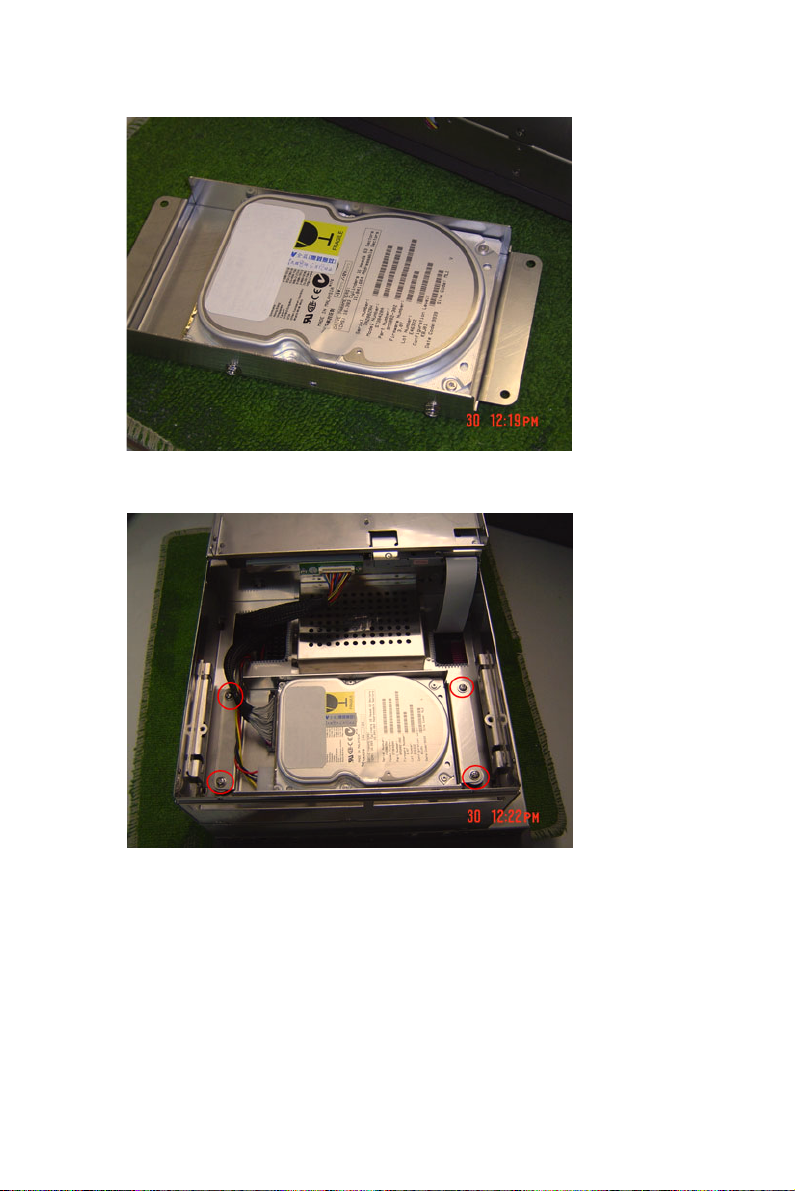
6. Insert the FDD, CD-ROM Module and fix the back cover.
17 Chapter 2
Page 30
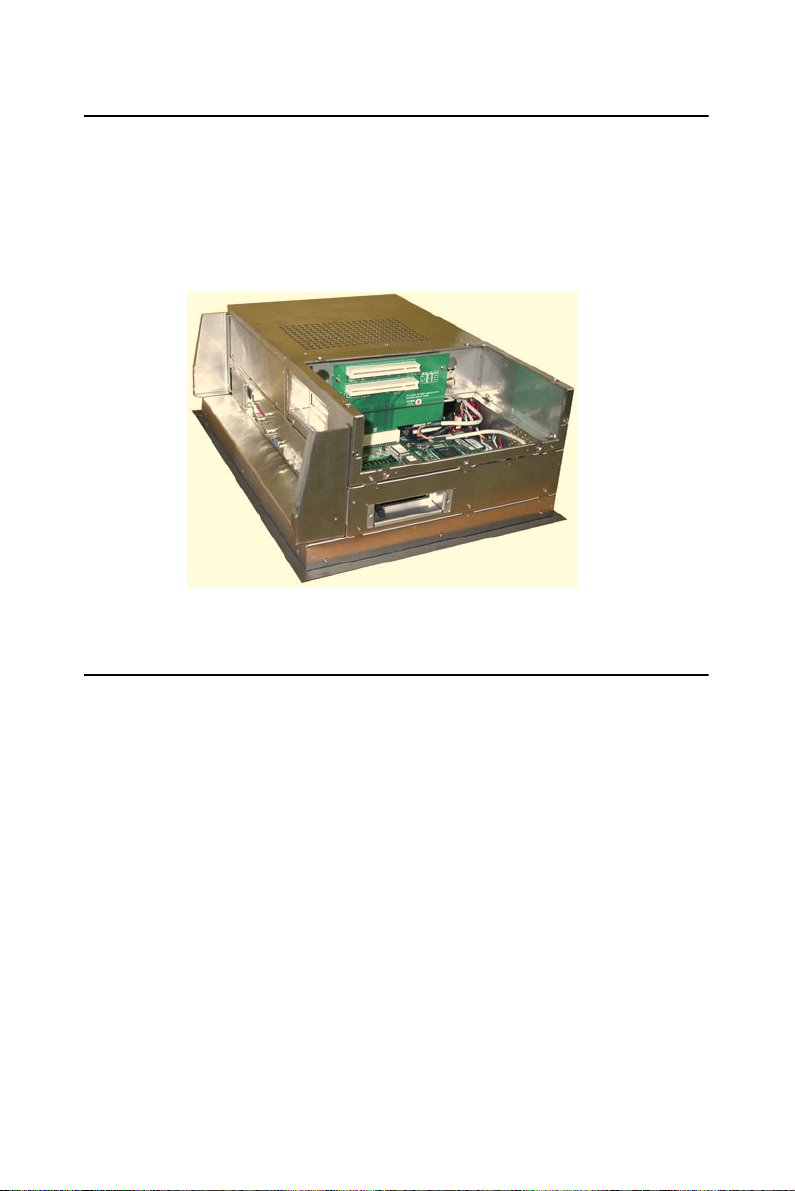
2.5 Installing Add-on Cards
This system supports two PCI expansion cards.
1. Detach the five screws on the back to open the lid.
2. Take away the slot bracket.
3. Insert the add-on card, and put on the lid.
2.6 Mounting Instructions
There are two ways to mount the system: panel mounting or rack mounting.
2.6.1 Panel Mounting
1. Take the four mounting brackets out of the accessory box.
2. Attach the four mounting brackets by inserting the screws into the
keyhole slots on the cover of the monitor.
3. Use the screws to secure the brackets to the cover. Tighten the screws
to secure the monitor to the back panel.
2.6.2 Rack Mounting
The monitor can be mounted to a 19" industrial rack with an optional
bracket.
IPPC-9151 Series Users Manual 18
Page 31

Jumper Settings
and Connectors
This chapter tells how to set up the
panel PC hardware, including instructions on setting jumpers and connecting
peripherals, switches and indicators. Be
sure to read all the safety precautions
before you begin the installation procedures.
Sections include:
• Jumpers and Connectors
• CPU Installation
• CMOS Clear for External RTC (JP8)
• COM-port Interface
• Internal -12 V Source Selection Setting (JP1)
• VGA Interface
• Watchdog Timer Configuration
3
CHAPTER
Page 32

Chapter 3 Jumper Settings &
Connectors
3.1 Jumpers and Connectors
3.1.1 Setting jumpers
You can configure your panel PC to match the needs of your application
by setting jumpers. A jumper is the simplest kind of electrical switch. It
consists of two metal pins and a small metal clip (often protected by a
plastic cover) that slides over the pins to connect them. To “close” a
jumper, you connect the pins with the clip. To “open” a jumper you
remove the clip. Sometimes a jumper will have three pins, labeled 1, 2,
and 3. In this case, you would connect either pins 1 and 2 or pins 2 and 3.
open closed closed 2-3
The jumper settings are schematically depicted in this manual as follows:.
12
open closed closed 2-3
A pair of needle-nose pliers may be helpful when working with jumpers.
If you have any doubts about the best hardware configuration for your
application, contact your local distributor or sales representative before
you make any changes.
PPC-154 User’s Manual 20
12
1 23
Page 33

3.1.2 Jumpers and switches
The motherboard of the IPPC-9151 has a number of jumpers that allow
you to configure your system to suit your applications. The table below
lists the function of each of the board’s jumpers.
Table 3.1: Jumpers, switches and their functions
Label Function
JP1 FSB (Front Side Bus) Setting
JP2 LCD Power Setting
JP3 Clear CMOS
JP4 COM2 RS232/422/485 jumper setting
JP5 COM1/COM2 pin 9 output type setting
JP6 PS2 Interface for touchscreen
SW1 Panel type setting
1
3.1.3 Jumper Locations
Figure 3.1: Jumpers on the IPPC-9151 motherboard
21 Chapter 3
Page 34

3.1.4 Connectors
Onboard connectors link the panel PC to external devices such as hard
disk drives or floppy drives. The table below lists the function of each of
the board’s connectors.
Table 3.2: Panel PC connectors
Label Function
CN1 ATX 20 pin power connector
CN2 ATX 12V Power connector
CN4 LVDS connector 1
CN5 Invertor Power connector 2
CN6 LVDS connector 2
CN9 FDD Connector
CN15 Internal Speaker Connector
CN16 EIDE HDD connector
CN17 CD-ROM Connector
CN24 IR connector
CN25 USB4/5 connector
FAN1 CPU fan power connector
FAN2 System fan power connector
PCI1 PCI1 PCI bus expansion slot
PPC-154 User’s Manual 22
Page 35

3.1.5 Locating connectors
Figure 3.2: Connectors on IPPC-9151 motherboard
23 Chapter 3
Page 36

3.2 CPU Installation
You can install an Intel Pentium 4 or Celeron CPU without setting any
frequency ratio or voltage.
Warning! To avoid damaging the computer, always turn off
the power supply before setting “Clear CMOS”.
Set the jumper back to “Normal operation” before
turning on the power supply.
Table 3.3: Front Side Bus Setting (JP1)
*Decided by CPU Select 100 MHz Select 133 MHz
123 1231 23 123
1 23
*Default setting
3.3 CMOS Clear for External RTC (JP3)
This jumper is used to erase CMOS data and reset system BIOS information.
The procedure for clearing CMOS is:
1. Turn off system.
2. Short pin 2 and pin 3.
3. Return jumper to pins 1 and 2.
4. Turn on the system. The BIOS is now reset to its default setting.
Table 3.4: CMOS clear (JP3)
*Normal operation Clear CMOS
123 1231 23
* default setting
PPC-154 User’s Manual 24
Page 37

3.4 COM-port interface (JP4, JP5)
The panel PC provides two serial ports. COM1 (RS-232) and COM2 (RS232/422/485) in one COM port connector.
3.4.1 COM2 RS-232/422/485 setting (JP4)
COM2 can be configured to operate in RS-232, RS-422, or RS-485 mode.
This is done via JP6.
Table 3.5: COM2 RS-232/422/485 setting (JP4)
*RS-232
17
978531
1115 13
141618
13579131517 11
246810141618 12
6421012
RS-422
17
978531
1115 13
141618
13579131517 11
246810141618 12
6421012
RS-485
978531
17
1115 13
141618
6421012
* default setting
The IRQ and the address ranges for COM 1 and 2 are fixed. However, if
you wish to disable the port or change these parameters later you can do
this in the system BIOS setup. The table overleaf shows the default settings for the panel PC’s serial ports.
25 Chapter 3
Page 38

Table 3.6: COM 1/2 Pin 9 setting (JP5)
Select 5 V *Select Ring
123 1231 23
* default setting
3.5 VGA interface
The panel PC's AGP VGA interface can drive conventional CRT displays. It is also capable of driving a wide range of flat panel displays,
including electroluminescent (EL), gas plasma, passive LCD and active
LCD displays.
3.5.1 LCD panel power setting
The panel PC's AGP SVGA interface supports 5 V and 3.3 V LCD displays. The LCD cable already has a built-in default setting. You do not
need to adjust any jumper or switch to select the panel power.
.
Table 3.7: LCD Panel Power Setting (JP2)
* Se le ct 5 V S el ec t 3. 3V
123 1231 23
*Default setting
PPC-154 User’s Manual 26
Page 39

Intel Chipset
This chapter provides information on
the Intel chipset configuration.
Sections include:
• Introduction
• Installation of chipset driver for
Windows 98/NT/ME/2000/XP
• Further Information
4
CHAPTER
Page 40

Chapter 4 Intel Chipset
4.1 Introduction
IPPC-9151 uses the 845GV chipset from Intel., with built-in high performance 2D/3D Intel Extreme Graphics 2, flexible 100/133MHz system
bus settings, support for DDR266 SDRAM and multiple power saving
modes. This makes Intel 845GV the ideal integrated SMA chipset for the
Intel Pentium 4 and Intel Celeron processors.
The VIA VT82C686B PSIPC (PCI Super-I/O Integrated Peripheral Controller) can support Intel and non-Intel based processor to PCI bus bridge
functionality to make a complete Microsoft PC99-compliant PCI/ISA
system, moreover, it also supports master mode enhanced IDE controller
with dual channel DMA engine (includes UltraDMA-33/66/100) and
interlaced dual channel commands.
4.2 Driver Installation
Before installing the driver, note the procedures below. You must know
which operating system you are using in your IPPC-9151, and then refer
to the corresponding installation flow chart. Then just follow the steps
described in the flow chart. You will quickly and successfully complete
the installation, even if you are not familiar with instructions for Win-
dows..
Important: 1. The following windows illustrations are exam-
ples only. You must follow the flow chart instructions and pay attention to the instructions which
then appear on your screen.
Notes: 1. The CD-ROM drive is designated as "D"
throughout this chapter.
2. <Enter> means pressing the "Enter" key on
the keyboard.
IPPC-9151 Series Users Manual 28
Page 41

4.2.1 Installation for Windows 98/NT/ME/2000/XP
1. a. Select "Start", "Run”.
b. Enter the driver path "D:\IPPC-9151G& 9171G_DRV&Utility
\Chipset Software\IAA Driver\2.3\iaa23_multi.exe".
c. Click “OK”.
2. Press "Next" to continue the installation.
3. When you finish the IAA driver installation. Please continue to install
the INF driver. The driver path "E:\IPPC-9151G&
9171G_DRV&Utility\Chipset Software\INF
Driver\4.30.1006\infinst_autol.exe"
29 Chapter 4
Page 42

4.3 Further Information
For further information about the AGP/VGA installation in your IPPC9151, including driver updates, troubleshooting guides and FAQ lists,
visit the following web resources:
Intel website: www.intel.com
Advantech website: www.advantech.com
If you need to know more details about installation, please refer to
\IPPC-9151G& 9171G_DRV&Utility\Chipset Software
IPPC-9151 Series Users Manual 30
Page 43

5
CHAPTER
PCI Bus Ethernet Interface
This chapter provides information on
Ethernet configuration.
Sections include:
• Introduction
• Installation of Ethernet Driver for
Windows 98/NT/ME/2000/XP
• Further Information
Page 44

Chapter 5 PCI Bus Ethernet Interface
5.1 Introduction
The IPPC-9151series is equipped with a high performance 32-bit Ethernet chipset, which is fully compliant with IEEE 802.3 100 Mbps CSMA/
CD standards. It is supported by major network operating systems, and is
also both 100Base-T and 10Base-T compatible.
The Ethernet port provides a standard RJ-45 jack. The network boot feature can be utilized by incorporating the boot ROM image files for the
appropriate network operating system. The boot ROM BIOS files are
combined with system BIOS, which can be enabled/disabled in the BIOS
setup.
5.2 Installation of Ethernet Driver
Before installing the Ethernet driver, note the procedures below. You
must know which operating system you are using in your IPPC-9151, and
then refer to the corresponding installation flow chart. Then just follow
the steps described in the flow chart. You will quickly and successfully
complete the installation, even if you are not familiar with instructions for
Windows.
Important: The following Windows illustrations are examples only. You
must follow the flow chart instructions and pay attention to the instruc-
tions which then appear on your screen.
Note 1: The CD-ROM drive is designated as "D" through-
out this chapter.
Note 2: <Enter> means pressing the "Enter" key on the
keyboard.
IPPC-9151 Series Users Manual 32
Page 45

5.2.1 Installation for Windows 98/NT/ME/2000
1. a. Select "Start", "Run"
b. Enter the path, "D:\IPPC-9151G& 9171G_DRV&Utility
\Intel Lan 6.2\Setup.exe"
c. Click "OK"
2. a. Click "Next”
3. Read the license agreement and click "Yes" if you accept the terms
and wish to continue.
b. Click "Next"
33 Chapter 5
Page 46
4. a. Click "Next"
5. a. Click "Install"
IPPC-9151 Series Users Manual 34
Page 47
6. a. Click "Finish"
5.3 Further Information
Intel website: www.intel.com
Advantech website: www.advantech.com
35 Chapter 5
Page 48

IPPC-9151 Series Users Manual 36
Page 49

2
6
CHAPTER
VGA Setup
This chapter provides information on
the VGA setup.
Sections include:
• Introduction
• Installation of VGA Drivers
- for Windows 98/2000/ME
- for Windows NT
- for Windows XP
• Further Information
Page 50

Chapter 6 VGA Setup
6.1 Introduction
The IPPC-9151 has an onboard AGP flat panel/VGA interface. The specifications and features are described as follows:
6.1.1 Chipset
IPPC-9151 uses a 845G chipset from Intel for its controller. It supports
many popular LCDs, and LVDS LCD displays and conventional analog
CRT monitors. The 845G VGA BIOS supports color TFT and DSTN
LCD flat panel displays. In addition, it also supports interlaced and noninterlaced analog monitors (color and monochrome VGA) in high-resolution modes while
maintaining complete IBM VGA compatibility. Digital monitors
(i.e. MDA, CGA, and EGA) are NOT supported. Multiple frequency
(multisync) monitors are handled as if they were analog monitors.
6.1.2 Display memory
The 845G chip can support 8MB frame buffer shared with system memory; the VGA controller can drive CRT displays or color panel displays
with resolutions up to 1024 x 768 @ 256K colors.
6.1.3 Display types
CRT and panel displays can be used simultaneously. The IPPC-9151 can
be set in one of three configurations: on a CRT, on a flat panel display, or
on both simultaneously. The system is initially set to simultaneous display mode. If you want to enable the CRT display only or the flat panel
display only, please contact Intel, or our sales representative for detailed
information.
IPPC-9151 Series Users Manual 38
Page 51

6.2 Installation of the VGA Driver
Complete the following steps to install the VGA driver. Follow the procedures in the flow chart that apply to the operating system that you are
using within your IPPC-9151.
6.2.1 Installation for Windows 95/98/ME
1. a. Select "Start", "Run"
b. Enter the path "D:\IPPC-9151G& 9171G_DRV&Utility
\VGA\WIN9X_ME\SETUP.EXE”
Notes: 1. Installation for Windows 2000, please type
the path "D:\IPPC-9151G& 9171G_DRV&Utility
\VGA\Win2K_XP\Setup.exe"
2. Installation for Win NT, please type the path
"D:\IPPC-9151G& 9171G_DRV&Utility
\VGA\WinNT4\winnt4m1141.exe"
2. Click "Next" on the Welcome screen.
39 Chapter 6
Page 52

3. Read the license agreement and click "Yes" if you accept the terms
and wish to continue.
4. The driver files will now be installed. When the install finishes,
choose the "Yes." option to restart, and click "Finish" to restart
your computer. The driver will now be loaded.
6.3 Further Information
For further information about the AGP/VGA installation in your IPPC9151, including driver updates, troubleshooting guides and FAQ lists,
visit the following web resources:
Intel website: www.intel.com
Advantech website: www.advantech.com
IPPC-9151 Series Users Manual 40
Page 53

Audio Setup
This chapter provides information on
the Audio setup.
Sections include:
• Introduction
• Installation of Audio Driver
- for Windows 98/2000/ME
- for Windows NT
- for Windows XP
7
CHAPTER
Page 54

Chapter 7 Audio Setup
7.1 Introduction
The IPPC-9151's on-board audio interface provides high-quality stereo
sound and FM music synthesis (ESFM) by using the VIA VT82C686
audio controller from VIA. The audio interface can record, compress, and
play back voice, sound, and music with built-in mixer control.
The IPPC-9151 on board audio interface also supports the Plug & Play
(PnP) standard and provides PnP configuration for the audio, FM, and
MPU-104 logical devices. It is compatible with Sound Blaster™; Sound
Blaster Pro™ version 3.01, voice and music functions. The ESFM synthesizer is register compatible with the OPL3 and has extended capabilities.
7.2 Installation of the Audio Driver
Before installing the audio driver, please take note of the procedures
detailed below. You must know which operating system you are using in
your IPPC-9151, and then refer to the corresponding installation flow
chart. Just follow the steps in the flow chart. You can quickly and successfully complete the installation, even though you are not familiar with
instructions for Windows.
Notes: 1. The windows illustrations in this chapter are
intended as examples only. Please follow the
listed steps, and pay attention to the instructions
which appear on your screen.
2. For convenience, the CD-ROM drive is designated as "D" throughout this chapter.
3. <Enter> means pressing the “Enter” key on
the keyboard.
IPPC-9151 Series Users Manual 42
Page 55

7.2.1 Installation for Windows 98/ME/2000/XP
1. a. Select "Start", "Run"
b. Enter the path "D:\IPPC-9151G& 9171G_DRV&Utility
\ALC202\WinXP_2K_Me_9X\Setup.exe"
Notes: 1. Installation for Windows 95, please Type the
path "D:\IPPC-9151G& 9171G_DRV&Utility
\ALC202\win95\Setup.exe"
2. Installation for Windows NT, please Type the
path "D:\IPPC-9151G& 9171G_DRV&Utility
\ALC202\winnt\Setup.exe"
2. Click "Finish"
43 Chapter 7
Page 56

IPPC-9151 Series Users Manual 44
Page 57

2
8
CHAPTER
Touchscreen
This chapter contains information on
the touchscreen, its installation and
configuration.
Page 58

Chapter 8 Touchscreen
8.1 Introduction
The IPPC-9151 Series’ optional touchscreen uses advanced 8-wire resistive technology. It provides more accurate sensing capacity than other
technologies. The touchscreen is specially designed for tough industrial
environments, and has been approved to FCC Class B standards.
8.2 Touchscreen Specifications
Electrical
• Contact bounce: < 10 ms
• Operating voltage: 5 V (typical)
• Sheet Resistance: 350 +/- 22% per Square.
• Linearity: <1.5% full scale linearity error in either direction.
• Insulation Resistance: >20 M @ 25VDC
Durability
• Test conditions: 4 H hardness, 0.04" stylus pen, 350 gram load
• Point activation:
1 Million activations on a single point with a 5/8" diameter silicone
finger with a 350g load at 2 Hz
• Character Activation Life:
>100,000 characters written within a 20 mm x 20 mm area on the touch
screen.
• Chemical resistance:
Hard coating is highly resistant to most solvents and chemicals
Optical
IPPC-9151 Series Users Manual 46
Page 59

• Visible light transmission: 75% typical (>74% @ 550 nm test)
• Clarity: Clear Finish - 25%, Antiglare Finish - 15%
Sensor board
• Chemical strengthened glass with 4 H hardness standard.
(Test condition: ASTM D3363-92A)
Ball drop test
• Able to bear a 225 g steel ball dropped from 660 mm elevation without
breaking
Environmental Specifications
• Operating Temperature Range: -20° C ~ +50° C, 2 weeks at 50° C /
90% RH.
• Storage Temperature High: +70° C, 240 hours at ambient humidity.
• Storage Temperature Low: -40° C, continuous at ambient humidity.
• Accelerated Aging: 100 hours at 60° C / 95% RH.
• Thermal Shock: 25 cycles (one cycle is 30 min. dwell alternating from
-40 to +85° C with less than 10 min. transfer time.
8.3 Installing Driver for Windows 2000/XP
The touchscreen has drivers for Windows 2000 and Windows XP. You
should read the instructions in this chapter carefully before you attempt
installation.
Note 1: The following windows illustrations are examples
only. You must follow the flow chart instructions
and pay attention to the instructions which then
appear on your screen.
Note 2: Install the HMI CD Driver into the system
CD-ROM (D:\ means CD-ROM)
Before installing the Windows 2000/XP driver software, you must have
the Windows 2000/XP system installed and running on your computer.
47 Appendix 8
Page 60

You must also have one of the following PenMount Serial Interface controller boards installed: 90A4, 9026B, 9036 or 9084. Contents of the PenMount Windows 2000/XP driver folder are listed below.
DMC9000.inf
DMC9000.sys
DMC9000.cat
SETUP.EXE
If you have an older version of the PenMount Windows 2000/XP driver
installed in your system, please remove it first. Follow the steps below to
install the PenMount Windows 2000/XP driver.
1. When the system first detects the controller board, a screen appears
that shows “Unknown Device.” Do not use this hardware wizard.
Press Cancel.
IPPC-9151 Series Users Manual 48
Page 61
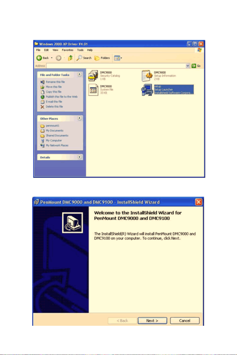
2. Insert the PenMount Driver CD-ROM. Go to the Windows 2000XP Driver folder. Click setup.exe.
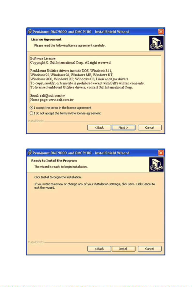
3. The screen displays the installation wizard for the PenMount software. Click “Next”.
49 Appendix 8
Page 62
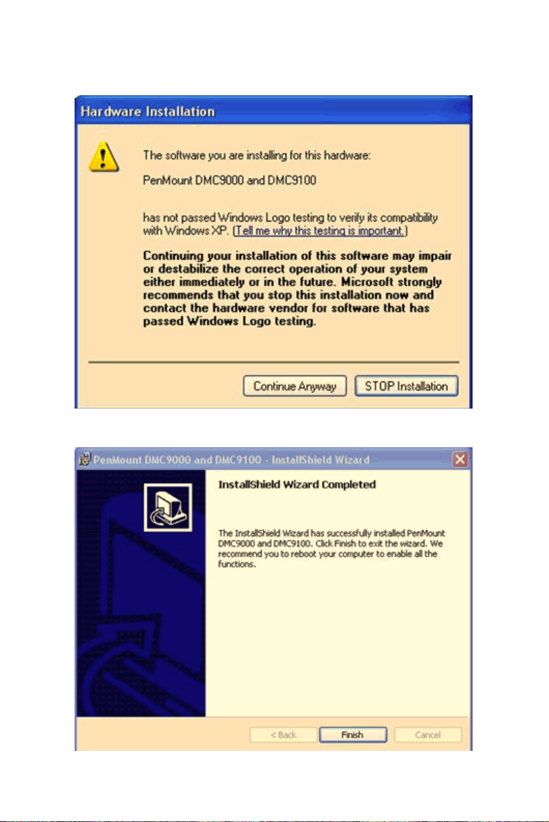
4. A License Agreement appears. Click “I accept…” and “Next”
5. The “Ready to Install the Program” screen appears. Select “Install.”
IPPC-9151 Series Users Manual 50
Page 63
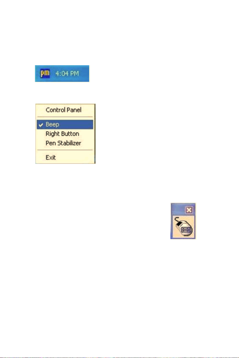
6. The next screen is “Hardware Installation.” Select “Continue Anyway.”
7. The “InstallShield Wizard Completed” appears. Click “Finish.”
51 Appendix 8
Page 64

8.4 Configuring PenMount Windows 2000/XP Driver
Upon rebooting, the computer automatically finds the new 9000 controller board. The touch screen is connected but not calibrated. Follow the
procedures below to carry out calibration.
1. After installation, click the PenMount Monitor icon “PM” in the
menu bar.
2. When the PenMount Control Panel appears, click “Calibrate.”
8.4.1 PenMount Control Panel
The functions of the PenMount Control Panel are Calibrate, Draw, Multiple Monitors, Option, and About, which are explained in the following
sections.
Calibrate
This function offers two ways to calibrate your touch screen. ‘Standard
Calibration’ adjusts most touch screens. ‘Advanced Calibration’ adjusts
aging touch screens.
Standard
Calibration
Advanced
Calibration
IPPC-9151 Series Users Manual 52
Click this button and arrows appear pointing to red
squares. Use your finger or stylus to touch the red
squares in sequence. After the fifth red point calibration
is complete. To skip, press ‘ESC’.
Advanced Calibration uses 4, 9, 16 or 25 points to effectively calibrate touch panel linearity of aged touch
screens. Click this button and touch the red squares in
sequence with a stylus. To skip, press ‘ESC’.
Page 65

NOTE: The older the touch screen, the more
Advanced Mode calibration points you need for
an accurate calibration. Use a stylus during
Advanced Calibration for greater accuracy.
53 Appendix 8
Page 66

IPPC-9151 Series Users Manual 54
Page 67

Plot Calibration Data
Check this function and a touch panel linearity comparison graph appears when you have finished
Advanced Calibration. The blue lines show linearity
before calibration and black lines show linearity after
calibration.
55 Appendix 8
Page 68

Draw
Tests or demonstrates the PenMount touch screen operation. The display
shows touch location. Click Draw to start. Touch the screen with your
finger or a stylus and the drawing screen registers touch activity such left,
right, up, down, pen up, and pen down.
Touch the screen with your finger or a stylus and the drawing screen registers touch activity such left, right, up, down, pen up, and pen down.
Click Clear Screen to clear the drawing.
IPPC-9151 Series Users Manual 56
Page 69

Multiple Monitors
Multiple Monitors supports from two to six touch screen displays for one
system. The PenMount drivers for Windows 2000/XP support Multiple
Monitors. This function supports from two to six touch screen displays
for one system. Each monitor requires its own PenMount touch screen
control board, either installed inside the display or in a central unit. The
PenMount control boards must be connected to the computer COM ports
via the RS-232 interface. Driver installation procedures are the same as
for a single monitor. Multiple Monitors supports the following modes:
Windows Extend Monitor Function
Matrox DualHead Multi-Screen Function
nVidia nView Function
NOTE: The Multiple Monitors function is for use with
multiple displays only. Do not use this function
if you have only one touch screen display.
Please note once you turn on this function the
Rotating function is disabled.
Enable the multiple display function as follows:
1. Check the Enable Multiple Monitor Support box; then click
Map Touch Screens to assign touch controllers to displays.
57 Appendix 8
Page 70

2. When the mapping screen message appears, click OK.
3. Touch each screen as it displays “Please touch this monitor.” Following this sequence and touching each screen is called mapping
the touch screens.
IPPC-9151 Series Users Manual 58
Page 71

4. Touching all screens completes the mapping and the desktop reappears on the monitors.
5. Select a display and execute the ‘Calibration’ function. A message
to start calibration appears. Click OK.
6. “Touch this screen to start its calibration” appears on one of the
screens. Touch the screen.
7. “Touch the red square” messages appear. Touch the red squares in
sequence.
8. Continue calibration for each monitor by clicking Standard Cali-
bration and touching the red squares.
59 Appendix 8
Page 72

NOTE: 1. If you used a single VGA output for multiple
monitors, please do not use the Multiple Monitors
function. Just follow the regular procedure for
calibration on each of your desktop monitors.
2. The Rotating function is disabled if you use the
Multiple Monitors function.
3. If you change the resolution of display or
screen address, you have to redo Map Touch
Screens so the system understands where the
displays are.
Option
This panel function supports two modes—Operation Mode and Beep
Sound Mode—which allow configuration for specific touch screen applications, such as point-of-sales (POS) terminals.
Operation
Mode
Beep
Sound
Mode
IPPC-9151 Series Users Manual 60
This mode enables and disables the mouse’s ability to
drag on-screen icons—useful for configuring POS terminals.
Stream Mode – Select this mode and the mouse functions as normal and allows dragging of icons.
Point Mode – Select this mode and the mouse only provides a click function, and dragging is disabled.
Enable Beep Sound – turns beep function on and off
Beep on Pen Down – beep occurs when pen comes
down
Beep on Pen Up – beep occurs when pen is lifted up
Beep on both of Pen Down/Up – beep occurs on both
Beep Frequency – modifies sound frequency
Beep Duration – modifies sound duration
Page 73

About
This panel displays information about the PenMount controller and driver
version.
61 Appendix 8
Page 74
8.4.2 PenMount Monitor Menu Icon
The PenMount monitor icon (PM) appears in the menu bar of Windows
2000/XP system when you turn on PenMount Monitor in PenMount Utilities.
PenMount Monitor has the following functions.
Beep Turns beep on or off.
Right
Button
Pen Stabilizer
Exit Exits the PenMount Monitor function.
IPPC-9151 Series Users Manual 62
When you select this function, a mouse
icon appears in the right-bottom of the
screen. Click this icon to switch between
Right and Left Button functions.
Check this function to reduce cursor vibration for relatively
unstable touch screens, or where there may be excess
vibration. Normally this function is not checked.
Page 75

8.4.3 PenMount Rotating Functions
The PenMount driver for Windows 2000/XP supports several display
rotating software packages. Please see Chapter 5 for more information.
The PenMount drivers for Windows 95, Windows 98/Me, Windows
2000/XP, as well as Windows 98 USB and Windows Me/2000/XP support display rotating software packages such as:
• Portrait’s Pivot Screen Rotation Software
• ATI Display Driver Rotate Function
• nVidia Display Driver Rotate Function
• SMI Display Driver Rotate Function
• Intel 845G/GE Display Driver Rotate Function
Configuring the Rotate Function
1. Install the rotation software package.
2. Choose the rotate function (0°, 90°, 180°, 270°) in the 3
software. The calibration screen appears automatically. Touch this
point and rotation is mapped.
rd
party
NOTE: The Rotate function is disabled if you use Monitor
Mapping
63 Appendix 8
Page 76

8.5 Uninstall the PenMount Windows 2000/XP driver
1. Exit the PenMount monitor (PM) in the menu bar.
2. Go to Settings, then Control Panel, and then click Add/Remove
program. Select PenMount DMC9000 and click the Add/Remove
button.
3. Select PenMount DMC9000 and DMC9100. Click the Remove
button.
4. Select ‘Yes’ and “Close” to remove the PenMount Windows 2000/
XP driver, and reboot the system.
IPPC-9151 Series Users Manual 64
Page 77

CHAPTER
PCMCIA
Sections include:
• Introduction
• Installation of PCMCIA driver for Windows
9
Page 78

Chapter 9 PCMCIA
9.1 Introduction
The IPPC-9151 is equipped with a high performance PCMCIA interface
which complies with the 1995 PCMCIA card standard by using the
RICOH Cardbus controller. The panel PC supports two PCMCIA card/
cardbus slots. Two sockets support both a 16-bit PCMCIA card and a 32bit Cardbus simultaneously, with hot insertion and removal.
9.2 Installation of PCMCIA Driver
The PCMCIA driver for Windows 95 is included in the "Drivers and Utilities" CD-ROM included with your IPPC-9151. The installation procedure is shown in the next section in this chapter.
Other operating systems such as Windows 98 and Windows NT also support PCMCIA drivers. However, the drivers for these operating systems
are not included in the "Drivers and Utilities" CD-ROM. Installation for
these operating systems is not explained in this manual..
Important: 1. The following windows illustrations are exam-
ples only. You must follow the flow chart instructions and pay attention to the instructions which
then appear on your screen.
Notes: 1. The CD-ROM drive is designated as "D"
throughout this chapter.
2. <Enter> means pressing the "Enter" key on
the keyboard.
IPPC-9151 Series Users Manual 66
Page 79
9.2.1 Installation for Windows
1. a. In "Start", "Run", type the path:
"D:\IPPC-9151G& 9171G_DRV&Utility\CardReader
\Drivers\Windows\Setup.exe"
2. a. Click "Next" to continue the installation.
3. a. Click "Yes".
67 Chapter 9
Page 80

IPPC-9151 Series Users Manual 68
Page 81

CHAPTER
Award BIOS Setup
This chapter describes how to set BIOS configuration data
10
Page 82

Chapter 10 Award BIOS Setup
10.1 Award BIOS Setup
The IPPC-9151 comes with an Award BIOS chip that contains the ROM
setup for your system. This chip serves as an interface between the processor and the rest of the mainboard's components. This chapter explains
the information contained in the setup program and tells you how to modify the settings according to your system configuration. Some setup items
will not be explained, because it is recommended that users do not change
such items.
Note: Values for the various setup items that appear on
your own screen (including default values) may
not be the same as the values shown on the
screen figures in this chapter. This is because
the BIOS is revised and updated from time to
time. If in doubt, check Advantech's website for
the latest BIOS versions and related information.
10.2 CMOS Setup Utility
A setup program, built into the system BIOS, is stored in the CMOS
RAM that allows the configuration settings to be changed. This program
is executed when the user changes the system configuration; when the
user changes the system backup battery; or when the system detects a
configuration error and asks the user to run the setup program. At poweron RAM testing, the message "Press DEL to enter Setup" appears. After
pressing the "DEL" key, the CMOS setup utility screen will appear as
shown in followings. Use the arrow keys to select and press "Enter" to
run the selected program.
IPPC-9151 Series Users Manual 70
Page 83

Standard CMOS Features
Advanced BIOS Features
Advanced Chipset Features
Integrated Peripherals
Power Management Setup
PnP/PCI Configurations
Frequency/Voltage Control
Load Optimized Defaults
Set Password
Save & Exit Setup
Exit without Saving
Esc : Quit
F10 : Save & Exit Setup
Time, Date, hard disk Type…
↑↓→← : Select Item
10.2.1 Standard CMOS Setup
Standard CMOS Setup records some basic system hardware configuration and sets the system clock and error handling. You only need to modify the configuration values of this option if you want to change your
system hardware configuration or when the data stored in the CMOS
memory gets lost or damaged.
Run the STANDARD CMOS SETUP as follows:
1. Choose “STANDARD CMOS SETUP” from the Main Menu and a
screen with a list of options will appear:
Date (mm:dd:yy) Mon, January 1 2001 Item Help
Time (hh:mm:ss)
IDE Primary Master
IDE Primary Slave
IDE Secondary Master
IDE Secondary Slave
Drive A
Drive B
Video
Halt On
Select Display Device
TV Type
Base Memory
Extended Memory
Total Memory
12 : 05 : 55
None
None
None
None
1.44M, 3.5 in.
None
EGA/VGA
All Errors
Auto
NTSC
640K
31744K
32768K
Menu Level
Figure 10.1: Standard CMOS features
71 Chapter 10
Page 84

2. Use one of the arrow keys to move between options and modify the
selected options by using PgUp / PgDn / + / - keys.
Date (mm:dd:yy)
The BIOS determines the day of the week from the other date information. This field is for information only. Press the left or right arrow key to
move to the desired field (date, month, year). Press the PgUp or PgDn key
to increment the setting, or type the desired value into the field.
Time (hh:mm:ss)
The time format is based on the 24-hour military-time clock. For example, 1 p.m. is 13:00:00. Press the left or right arrow key to move to
desired field. Press the PgUp or PgDn key to increment the setting, or
type the desired value into the field.
Primary / Secondary & Master / Slave
This field records the specifications for all non-SCSI hard disk drives
installed in your system. Refer to the respective documentation on how to
install the drives.
IDE HDD Auto-Detection Press Enter Item Help
IDE Primary Master
Access mode
Capacity
Cylinder
Head
Percomp
Landing Zone
Sector
Auto
Auto
13022 MB
25232
16
0
25231
63
Figure 10.2: Standard CMOS features
IPPC-9151 Series Users Manual 72
Menu Level
Page 85

Drive A / Drive B
Select this field to the type(s) of floppy disk drive(s) installed in your system. The choices are:
360 KB, 5.25 in;
1.2 MB, 5.25 in;
720 KB, 3.5 in;
1.44 MB, 3.5 in;
2.88 MB, 3.5 in;
None.
Video
Select the type of primary video subsystem in your computer. The BIOS
usually detects the correct video type automatically. The BIOS supports a
secondary video subsystem, but you do not select it in setup.
Halt On
During the power-on self-test (POST), the computer stops if the BIOS
detects a hardware error. You can tell the BIOS to ignore certain errors
during POST and continue the boot-up process.
Select Display Device
Select this field to the display device. The choices are:
Auto
CRT
LCD
CRT+LCD
TV
CRT+TV
TV Type
Select this field to the type of TV. The choices are:
NTSC
PAL
73 Chapter 10
Page 86

Base Memory
Typically 640KB. Also called conventional memory. The DOS operating
system and conventional applications use this area.
Extended Memory
Above the 1MB boundary. Early IBM personal computers could not use
memory above 1MB, but current PCs and their software can use extended
memory.
Total Memory
This option shows system memory capacity.
3. Press <ESC> to return to the Main Menu when you finish setting
up all items.
10.3 Advanced BIOS Features
Advanced BIOS Features improves your system performance or sets up
system features according to your preference.
Run the ADVANCED BIOS FEATURES as follows:
1. Choose“Advanced BIOS Features”from the Main Menu and a
screen with a list of options will appear.
2. Use one of the arrow keys to move between options and modify the
selected options by using PgUp / PgDn / + / - keys.
IPPC-9151 Series Users Manual 74
Page 87

Virus Warning Disabled Item Help
CPU Internal Cache
External Cache
CPU L2 Cache ECC Checking
Processor Number Feature
Quick Power On Self Test
First Boot Device
Second Boot Device
Third Boot Device
Boot Other Device
Swap Floppy Drive
Boot Up Floppy Seek
Boot Up NumLock Status
Gate A20 Option
Typematic Rate Setting
Typematic Rate (Chars/Sec)
Typematic Delay (Msec)
Security Option
PS/2 Mouse Function
OS Select For DRAM > 64MB
Reports No FDD For Win95
Video BIOS Shadow
C8000-CBFFF Shadow
CC000-CFFFF Shadow
D0000-D3FFF Shadow
D4000-D7FFF Shadow
D8000-DBFFF Shadow
DC000-DFFFF Shadow
Small Logo (EPA) Show
Enabled
Enabled
Enabled
Enabled
Enabled
Floppy
HDD-0
CDROM
Enabled
Disabled
Enabled
On
Fast
Disabled
6
250
Setup
Non-OS2
Enabled
Disabled
Disabled
Disabled
Disabled
Disabled
Disabled
Menu Level
Virus Warning
When enabled, you receive a warning message if a program (specifically,
a virus) attempts to write to the boot sector or the partition table of the
hard disk drive.
You should then run an antivirus program. Keep in mind that this feature
protects only the boot sector, not the entire hard drive.
Note: Many disk diagnostic programs that access the boot
sector table can trigger the virus warning message. If
you plan to run such a program, we recommend that
you disable the virus warning.
75 Chapter 10
Page 88

CPU Internal Cache/External Cache
Cache memory is additional memory that is much faster than conventional DRAM (system memory). CPUs from 486-type up contain internal
cache memory, and most, but not all, modern PCs have additional (external) cache memory. When the CPU requests data, the system transfers the
requested data from the main DRAM into cache memory, for faster
access by the CPU.
CPU L2 Cache ECC Checking
When you select Enabled, it will speed up memory checking when the
external cache contains ECC SRAMs. The choices: Enabled; Disabled.
Processor Number Feature
Choose Disabled or Enabled. When enabled, the processor serial number
will display during the boot up screen.
Quick Power On Self Test
Select Enabled to reduce the amount of time required to run the power-on
self-test (POST). A quick POST skips certain steps. We recommend that
you normally enable quick POST.
First/Second/Third/Other Boot Device
The BIOS attempts to load the operating system from the devices in the
sequence selected in these items. The choices: Floppy; LS/ZIP; HDD;
SCSI; CDROM; Disabled.
Swap Floppy Drive
When enabled, floppy drives A and B will be exchanging without any
physical connection and modification on the cables.
Boot Up Floppy Seek
When enabled, the BIOS tests (seeks) floppy drives to determine whether
they have 40 or 80 tracks. Only 360-KB floppy drives have 40 tracks;
drives with 270KB, 1.2MB, and 1.44MB capacity all have 80 tracks.
Because very few modern PCs have 40-track floppy drives, we recommend that you set this field to disabled to save time.
Boot Up NumLock Status
Toggle between On or Off to control the state of the NumLock key when
the system boots. If On, the numeric keypad is in numeric mode. If off,
the numeric keypad is in cursor control mode.
IPPC-9151 Series Users Manual 76
Page 89

Gate A20 Option
Gate A20 refers to the way the system addresses memory above 1 MB
(extended memory). When set to Fast, the system chipset controls Gate
A20. When set to Normal, a pin in the keyboard controller controls Gate
A20. Setting Gate A20 to Fast improves system speed, particularly with
OS/2 and Windows.
Typematic Rate Setting
When Disabled, the following two items (Typematic Rate and Typematic
Delay) are irrelevant. Keystroke repeats at a rate determined by the keyboard controller in your system. When Enabled, you can select a typematic rate and typematic delay.
Typematic Rate (Chars / Sec)
When the typematic rate setting is enabled, you can select a typematic
rate (the rate at which character repeats when you hold down a key) of 6,
8, 10, 12, 15, 20, 24, or 30 characters per second.
Typematic Delay (Msec)
Choices: 250; 500; 750; 1000. This option sets the time interval for displaying the first and the second characters. If enabled, the time interval is
optional.
Security Option
If you have set a password, select whether the password is required every
time the System boots, or only when you enter setup. The choices: system; setup.
PS/2 Mouse Function
Disabled: Prevents any installed PS/2 mouse from functioning but free up
occupied IRQ.
Enabled: Allows the operating system to determine whether to enable or
disable the mouse.
OS Select For DRAM > 64MB
Select OS2 only if you are running OS/2 operating system with greater
than 64MB of RAM on your system.
Reports No FDD For Win95
Video BIOS Shadow
Performance will be improved by copying Video BIOS to Shadow RAM.
77 Chapter 10
Page 90

C8000-CBFFF to DC000-DFFFF Shadow
These options are used to shadow other expansion card ROMs.
Small Logo (EPA) show
3. Press <ESC> to return to the Main Menu when you finish setting
up all items.
10.4 Advanced Chipset Features
Advanced Chipset Features is used to modify the values of chipset buffers. These buffers control the system options.
Run the Advanced Chipset Features as follows:
1. Choose “Advanced Chipset Features” from the Main Menu and a list of
options will appear.
DRAM Timing by SPD Enabled Item Help
DRAM Clock
SDRAM Cycle Length
B a nk Inte r le a ve
Memory Hole
P 2C /C 2P C o ncurre ncy
System B IOS C acheable
Video RAM Cacheable
Frame Buffer Size
AGP Aperture Size
APG-4X Mode
AGP Driving Control
AG P D riving Value
Boot De vice Select
OnC hip USB
USB Keyboard Support
OnChip Sound
C P U to P C I Wr ite Buffer
P C I D ynam ic B u rsti ng
PCI Master 0 WS Write
PC I D elay Transaction
PC I#2 Access #1 Retry
AGP Master 1 WS Write
AGP M aster 1 WS Read
Host CLK
3
Disabled
Enabled
Enabled
Enabled
Enabled
16M
64M
Enabled
Auto
DA
Both
Enabled
Disabled
Enabled
Enabled
Enabled
Enabled
Enabled
Disabled
Disabled
Disabled
Menu Level
Use one of the arrow keys to move between options and modify the
selected options by using PgUp / PgDn / + / - keys.
DRAM Timing by SPD
When this item is Enabled, DRAM Timing is set by SPD. SPD (Serial
Presence Detect) is located on the memory modules, BIOS reads information coded in SPD during system boot up.
IPPC-9151 Series Users Manual 78
Page 91

DRAM Clock
This item allows you to control the DRAM speed.
The choices are : Host Clock, HCLK+33M.
SDRAM Cycle Length
Select CAS latency time in HCLKs of 2 or 3. The system designer
already set the values. Do not change the default value unless you change
specifications of the installed DRAM or the installed CPU.
Bank Interleave
Please use default setting. The choices: Disabled; 2 Bank; 4 Bank.
Memory Hole
In order to improve performance, certain space in memory is reserved for
ISA cards. This memory must be mapped into the memory space below
16 MB. The choices: 15M-16M; Disabled.
P2C/C2P Concurrency
This item allows you to enable/disable the PCI to CPU, CPU to PCI concurrency. The choices: Enabled; Disabled.
System BIOS Cacheable
selecting Enabled allows caching of the system BIOS ROM at F0000hFFFFFh, resulting in better system performance.
Video RAM Cacheable
Selecting Enabled allows caching of the video memory (RAM) at
A0000h to AFFFFh, resulting in better video performance. However,
check your AGP manual to find out if any compatibility problem exists.
Frame Buffer size
This option allows you select memory size shared to on-chip graphics.
AGP Aperture Size
Series of options are available: 4, 8, 16, 32, 64, 128 or 256 MB. Memory
mapped and graphics data structures can reside in a Graphics Aperture.
This area is like a linear buffer. BIOS will automatically report the starting address of this buffer to the O.S. The default setting is 64 MB.
AGP– 4X Mode
This item allows you to enable AGP-4X mode. The choices are: Disabled, Enabled
79 Chapter 10
Page 92

AGP Driving Control
This item allows you to adjust the AGP driving force. Choose Manual to
key in a AGP Driving Value in the next selection. This field is recommended to set in Auto for avoiding any error in your system. The choice:
Manual, Auto.
AGP Driving Value
This item allows you to adjust the AGP driving force.
The choice: Min=0000 ~ Max=00FF.
Boot Device Select
This item allows you to select your boot display device. The choices are:
Both, Auto
OnChip USB
This should be enabled if our system has a USB installed on the system
board and you wish to use it. Even when so equipped, if you add a higher
performance controller, you will need to disable this feature.
The choices: Enabled; Disabled.
USB Keyboard Support
Enable function when the USB keyboard is being used. When the AT
keyboard is being used, choose disabled. The choices:Enabled; Disabled.
OnChip Sound
Select Enabled to use the on-chip Audio capability of your system. Most
of the following field do not appear when this field is Disabled. For user
who wants to use another sound card, this field must be Disabled.
CPU to PCI Write Buffer
When this field is Enabled, writes from the CPU to the PCI bus are buffered, to compensate for the speed differences between the CPU and the
PCI bus. When Disabled, the writes are not buffered and the CPU must
wait until the write is complete before starting another write cycle.
The choices: Enabled; Disabled.
PCI Dynamic Bursting
When Enabled, every write transaction goes to the write buffer. Bursting
transactions then burst on the PCI bus and non-bursting transactions
don’t. The choices: Enabled; Disabled.
IPPC-9151 Series Users Manual 80
Page 93

PCI Delay Transaction
Leave this field at default. The choice: Enabled, Disabled.
PCI Master 0 WS Write
When Enabled, writes to the PCI bus are executed with zero wait states.
The choice: Enabled, Disabled.
PCI # 2 Access # 1 Retry
Leave this field at default. The choice: Enabled, Disabled(default).
AGP Master 1 WS Write
Leave this field at default. The choice: Enabled, Disabled(default).
AGP Master 1 WS Read
Leave this field at default. The choice: Enabled, Disabled(default).
Press <ESC> to return to the Main Menu when you finish setting up all
items.
10.5 Integrated Peripherals
Integrated Peripherals option allows you to get some information inside
your system when it is working.
Run the INTEGRATED PERIPHERALS as follows:
1. Choose“Integrated Peripherals”from the Main Menu and a list of
options will appear.
2. Use one of the arrow keys to move between options and modify the
selected options by using PgUp / PgDn / + / - keys.
81 Chapter 10
Page 94

On-Chip IDE Channel 0 Enabled Item Help
On-Chip IDE Channel 1
IDE Prefetch Mode
Primary Master PIO
Primary Slave PIO
Secondary Master P IO
Secondary Slave P IO
Primary Master UDMA
Primary Slave UDMA
Secondary Master UD MA
Secondary Slave UDMA
Init Display First
IDE HDD Block Mode
Onboard FDD Controller
Onboard Serial Port 1
Onboard Serial Port 2
UART 2 Mode
IR Function D uple x
TX, RX invert ing ena ble
Onboard Parallel Port
Onboard Parallel Mode
ECP Mode Use DMA
Parallel Port EPP Type
Onboard Serial Port 3
Serial Port 3 use IRQ
Onboard Serial Port 4
Serial Port 4 Use IRQ
Onboard Legacy Audio
Sound Blaster
Enabled
Enabled
Auto
Auto
Auto
Auto
Auto
Auto
Auto
Auto
PCI Slot
Enabled
Enabled
Auto
Auto
Standard
Half
No, Yes
378/IRQ 7
Norm al
3
EPP1.9
Enabled
Disabled
Menu Level
OnChip IDE Channel 0/1
The chipset contains a PCI IDE interface with support from two IDE
channels. Select Enabled to activate the first and/or the second IDE interface. Select Disabled to inactivate an interface if you install a primary
and/or second add-on IDE interface. The choices: Enabled; Disabled.
IDE Prefetch Mode
The on-board IDE drive supports IDE prefetching for faster drive
accesses. If the IDE device doesn’t support prefetching, set this field to
Disabled. The choices: Enabled; Disabled.
IPPC-9151 Series Users Manual 82
Page 95

Primary Master / Slave PIO & Secondary Master / Slave PIO
Choose Auto or Mode 0~4. The BIOS will detect the HDD mode type
automatically when you choose Auto. You need to set to a lower mode
than Auto when your hard disk becomes unstable.
The choices: Auto; Mode 0; Mode 1; Mode 2; Mode 3; Mode 4.
Primary Master / Slave UDMA & Secondary Master / Slave UDMA
Ultra DMA33/66/100 implementation is possible only if your IDE hard
drive supports it, if the operating environment includes a DMA drive, and
if your system software both support Ultra DMA33/66/100. Select
“Auto” to enable BIOS support. The choices: Auto; Disabled.
Init Display First
Initialize the AGP video display before initializing any other display
device on the system. Thus the AGP display becomes the primary display. The choices: PCI Slot; AGP.
IDE HDD Block Mode
Block mode is also called block transfer, multiple commands, or multiple
sector read/write. If your IDE hard drive supports block mode (most new
drives do), select Enabled for automatic detection of the optimal number
of block read/write per sector the drive can support.
The choices: Enabled; Disabled.
Onboard FDD Controller
Select Enabled if your system has a floppy drive controller (FDC) installing in the system board and you want to use it. If you install add-in FDC
or the system has no floppy drive, select Disabled in this field. The
choices: Enabled; Disabled.
Onboard Serial Port 1 / Port2
Select an address and corresponding interrupt for the first and second
serial ports.
The choices: 3F8/IRQ4; 2E8/IRQ3; 3E8/IRQ4; 2F8/IRQ3; Disabled;
Auto.
UART 2 Mode
The second serial port on your system may offer a variety of infrared port
modes. Click here for a description of various modes. (Click your
browser’s Back button, or your right mouse button, to return to this page.)
The choices: Standard; HPSIR; ASKIR.
83 Chapter 10
Page 96

IR Function Duplex
This item allows you to select the IR half / full duplex function.
The choices: Half; Full.
TX, RX inverting enable
This item allows you to enable the TX, RX inverting which depends on
different H/W requirement. This field is not recommended to change its
default setting.
The choices: “No, No”; “No, Yes”; “Yes, No”; “Yes, Yes”.
Onboard Parallel Port
Select a logical LPT port name and matching address for the physical parallel (printer) port.
The choices: 378H/IRQ7; 278H/IRQ5; 3BC/IRQ7; Disabled.
Onboard Paralle Mode
Select an operating mode for the onboard parallel (printer) port. Select
Normal, Compatible, or SPP unless you are certain your hardware and
software both support one of the other available modes. The choices:
SPP; EPP; ECP; ECP + EPP.
ECP Mode Use DMA
Select a DMA channel for the parallel port for use during ECP mode.
The choices: 3; 1.
Parallel Port EPP Type
Select EPP port type 1.7 or 1.9. The choices: EPP1.7; 1.9.
Onboard Legacy Audio
This field controls the on-board audio.
• Sound Blaster
• SB I/O Base Address
• SB IRQ Select
• SB DMA Select
• MPU-401
• MPU-401 I/O Address
• Game Port (200-207H)
3. Press <ESC> to return to the Main Menu when you finish setting
up all items.
IPPC-9151 Series Users Manual 84
Page 97

10.6 Power Management Setup
POWER MANAGEMENT SETUP allows you to set the system’s power
saving functions.
Run the POWER MANAGEMENT SETUP as follows:
1. Choose“Integrated Peripherals”from the Main Menu and a list of
options will appear.
2. Use one of the arrow keys to move between options and modify the
selected options by using PgUp / PgDn / + / - keys.
ACPI Function Disabled Item Help
Power Management
PM Control by APM
Video Off Optio n
Video Off Method
MODEM Use IRQ
Soft-Off by PW RBTN
W a ke Up E ve nts
Press Enter
Ye s
Suspend --> Off
V/H SYNC +Blank
3
Ins ta n d -O ff
Press Enter
Menu Level
ACPI Function
Select Enabled only if your computer’s operating system supports the
Advanced Configuration and Power Interface (ACPI) specification. Currently, Windows NT 5.0 supports ACPI.
Power Management
When this opinion is chosen, the following item appears for user’s configuration.
P ower M a nagement User D efine Item H e lp
HDD Power Down
D oze M ode
S uspend M ode
D isable
D isable
D isable
M enu Level
85 Chapter 10
Page 98

• Power Management: This option allows you to select the type (or
degree) of power saving for Doze, Standby, and Suspend modes. This
table describes the power management modes for your reference:
Max Saving
User Define
Min Saving
Maximum power savings. Only Available for SL CPUs.
Inactivity period is 1 minute in each mode.
Set each mode individually. Select time-out peri od in
the section for each mode stated bel ow.
Minimum power savings. Inactivity period is 1 hour in
each mode (except the hard drive).
• HDD Power Down: When enabled and after the set time of system
inactivity, the hard disk drive will be powered down while all other
devices remain active.
• Suspend Mode: After the selected period of system inactivity, the
chipset enters a hardware suspend mode, stopping the CPU clock and
possibly causing other system devices to enter power management
modes.
• Doze Mode: After the selected period of system inactivity, the CPU
clock runs at slower speed while all other devices still operate at full
speed.
PM Control by APM
If Advanced Power Management (APM) is installed on your system,
selecting “Yes” gives better power savings. The Choices: Yes; No.
Video Off Option
When enabled, this feature allows the VGA adapter to operate in a power
saving mode.
Always On
Suspend ! Off
All Modes ! Off
Monitor will remain on during power saving modes.
Monitor blanked w hen the systems e nters the
Monitor blanked when the system enters either
Suspend mode.
Suspend or Standby modes.
IPPC-9151 Series Users Manual 86
Page 99

Video Off Method
This determines the manner in which the monitor is blanked.
This selection will cause the system to turn off the vertical
V/H SYNC + Blank
Blank Screen
DPMS Supports
and horizontal synchronization ports and write blanks to
This option only writes blanks to the vid eo buffer.
Select this option if you monitor supports th e Display Power
Management Signaling ( DPMS) standard of the Vide o Electronics
Standards to select video power management values.
video buffer.
MODEM Use IRQ
This determines the IRQ which the MODEM can use.
The choices: 3; 4; 5; 7; 9; 10; 11; NA.
Soft-Off by PWRBTN
When Enabled, turning the system off with the on/ off button places the
system in a very low-powerusage state, with only enough circuitry receiving power to detect power button activity or Resume by Ring activity.
WAKE UP EVENTS
When this option is chosen, the following item appears for user’s configuration.
V G A O ff Ite m H e lp
LPT & C OM
HDD & FDD
PCI Master
IR Q s A cti vit y
M o nitoring
LPT/COM
On
Off
Press Enter
Menu Level
• VGA: When Enabled, you can set the VGA awakens the system.
• LPT & COM: When LPT & COM is ON, any activity from one of the
listed system peripheral devices or IRQs wakes up the system.
• HDD & FDD: When HDD & FDD is ON, any activity from one of the
listed system peripheral devices wakes up the system.
• PCI Master: When PCI Master is ON, any activity from one of the
listed system peripheral devices wakes up the system.
87 Chapter 10
Page 100

• Primary INTR: When set to on, any event occurring at will awaken a
system which has been powered down.
On(default):The system can not enter the power saving mode when
I/O ports or IRQ# is activated. Off:The system still can enter the
power saving mode when I/O ports or IRQ# is activated.
• IRQ Activity Monitoring: The following is a list of IRQ’s (Interrupt
Requests), which can be exempted much as the COM ports and LPT
ports above can. When an I/O device wants to gain the attention of the
operating system, it signals this by causing an IRQ to occur. When the
operating system is ready to respond to the request, it interrupts itself
and performs the service. When set On, activity will neither prevent the
system from going into a power management mode nor awaken it.
When this option is chosen, the following item appears for user’s configuration.
IRQ-3 (COM2) Enabled Item Help
IRQ-4 (COM1)
IRQ-5 (LPT2)
IRQ-6 (Floppy Disk)
IRQ-7 (LPT1)
IRQ-8 (RTC Alarm)
IRQ-9 (IRQ2 Redir)
IRQ-10 (Reserved)
IRQ-11 (Reserved)
IRQ-12 (PS/2 Mouse)
IRQ 13 (Coprocessor)
IRQ 14 (Hard Disk)
IRQ 15 (Reserved)
Enabled
Enabled
Enabled
Enabled
Disabled
Disabled
Disabled
Disabled
Enabled
Disabled
Enabled
Disabled
Menu Level
3. Press <ESC> to return to the Main Menu when you finish setting
up all items.
IPPC-9151 Series Users Manual 88
 Loading...