

Page 1

IPPC-9120/9150 Series
Rugged Pentium®III/Celeron™
Industrial panel PC with
12.1"/15" LCD display
User’s Manual
Page 2
Copyright notice
This document is copyrighted 2001, by Advantech Co. Ltd. All rights are
reserved. Advantech Co., Ltd. reserves the right to alter the products described in this manual at any time without notice.
No part of this manual may be reproduced, copied, translated or
transmitted in any form or by any means without the prior written
permission of Advantech. Information provided in this manual is intended to
be accurate and reliable. However, Advantech assumes no responsibility for use
of this manual, nor for any infringements upon the rights of third parties
which may result from such use.
All brand and product names mentioned herein are trademarks or
registered trademarks of their respective holders.
Acknowledgments
ADAM is a trademark of Advantech Co., Ltd.
IBM and PC are trademarks of International Business Machines Corporation.
Part No. 2002000100
1st Edition Printed in Taiwan January 2001
Page 3

FCC Class B
This equipment has been tested and found to comply with the limits for a
Class B digital device, pursuant to Part 15 of the FCC Rules. These limits are
designed to provide reasonable protection against harmful interference when
the equipment is operated in a residential environment. This equipment
generates, uses and can radiate radio frequency energy. If not installed and
used in accordance with this user's manual, it may cause harmful interference
to radio communications. Note that even when this equipment is installed and
used in accordance with this user’s manual, there is still no guarantee that
interference will not occur. If this equipment is believed to be causing
harmful interference to radio or television reception, this can be determined
by turning the equipment on and off. If interference is occuring, the user is
encouraged to try to correct the interference by one or more of the following
measures:
• Reorient or relocate the receiving antenna
• Increase the separation between the equipment and the receiver
• Connect the equipment to a power outlet on a circuit different from that to
which the receiver is connected
• Consult a dealer or an experienced radio/TV technician for help
Warning: Any changes or modifications made to the equipment
which are not expressly approv ed by the relevant standards authority could void your authority to operate the
equipment.
Page 4

Packing List
Before setting up the system, check that the items listed below are included
and in good condition. If any item does not accord with the table, please
contact our dealer immediately.
The IPPC-9120/9150 Series industrial panel PCs include the following models:
1. IPPC-9120T
Rugged Pentium
®
III/Celeron™ industrial panel PC with 12.1” TFT LCD
2. IPPC-9120T-T
IPPC-9120T with resistive type touchscreen
3. IPPC-9150T
Rugged Pentium®III/Celeron™ industrial panel PC with 15” TFT LCD
4. IPPC-9150T-T
IPPC-9150T with resistive type touchscreen
5. IPPC-9150T-N
IPPC-9150T with NFI touchscreen
Page 5

Packing List
Item IPPC-9120T IPPC-9150T
Description
Rugged Pentium® III/Celeron™
industrial panel PC with LCD display
LCD type 12.1" TFT SVGA 15" TFT XGA
Display
resolution
800 x 600 1024 x 768
Motherboard PCM-9571B
Floppy disk
drive
Power supply 80 W; 100 ~ 250 V
3.5" slim type
AC
One utility CD-ROM
Items in
One CPU fan with heat sink
accessory box
One Y-shaped adapter for PS/2 mouse
and PS/2 keyboard
Optional Devices
Touchscreen Resistive Resistive or NFI
24X slim type CD-ROM
Slim type CD-
ROM drive
One floppy disk with CD-ROM drive
Page 6

Additional Information and Assistance
1. Visit the Advantech websites at www.advantech.com or
www.advantech.com.tw, where you can find the latest information about
the product.
2. Contact your distributor, sales representative, or Advantech's customer
service center for technical support if you need additional assistance.
Please have the following information ready before you call:
• Product name and serial number
• Description of your peripheral attachments
• Description of your software (operating system, version, application
software, etc.)
• A complete description of the problem
• The exact wording of any error messages
Page 7

Safety Instructions
1. Read these safety instructions carefully.
2. Keep this User's Manual for later reference.
3. Disconnect this equipment from any AC outlet before cleaning. Use a damp cloth. Do not
use liquid or spray detergents for cleaning.
4. For plug-in equipment, the power outlet socket must be located near the
equipment and must be easily accessible.
5. Keep this equipment away from humidity.
6. Put this equipment on a reliable surface during installation. Dropping it or letting it fall
may cause damage.
7. The openings on the enclosure are for air convection. Protect the equipment from
overheating. DO NOT COVER THE OPENINGS.
8. Make sure the voltage of the power source is correct before connecting the equipment to
the power outlet.
9. Position the power cord so that people cannot step on it. Do not place anything over the
power cord.
10. All cautions and warnings on the equipment should be noted.
11. If the equipment is not used for a long time, disconnect it from the power source to avoid
damage by transient overvoltage.
12. Never pour any liquid into an opening. This may cause fire or electrical shock.
13. Never open the equipment. For safety reasons, the equipment should be opened only by
qualified service personnel.
14. If one of the following situations arises, get the equipment checked by service personnel:
a. The power cord or plug is damaged.
b. Liquid has penetrated into the equipment.
c. The equipment has been exposed to moisture.
d. The equipment does not work well, or you cannot get it to work according to the
user's manual.
e. The equipment has been dropped and damaged.
f. The equipment has obvious signs of breakage.
15. DO NOT LEAVE THIS EQUIPMENT IN AN UNCONTROLLED
ENVIRONMENT WHERE THE STORAGE TEMPERATURE IS BELOW
-20° C (-4° F) OR ABOVE 60° C (140° F). THIS MAY DAMAGE THE EQUIPMENT.
The sound pressure level at the operator's position according to IEC 704-1:1982 is no
more than 70dB(A).
DISCLAIMER: This set of instructions is given according to IEC 704-1. Advantech
disclaims all responsibility for the accuracy of any statements contained herein.
Page 8

Wichtige Sicherheishinweise
1. Bitte lesen sie Sich diese Hinweise sorgfältig durch.
2. Heben Sie diese Anleitung für den späteren Gebrauch auf.
3. Vor jedem Reinigen ist das Gerät vom Stromnetz zu trennen. Verwenden Sie Keine
Flüssig-oder Aerosolreiniger. Am besten dient ein angefeuchtetes Tuch zur Reinigung.
4. Die NetzanschluBsteckdose soll nahe dem Gerät angebracht und leicht zugänglich sein.
5. Das Gerät ist vor Feuchtigkeit zu schützen.
6. Bei der Aufstellung des Gerätes ist auf sicheren Stand zu achten. Ein Kippen oder Fallen
könnte Verletzungen hervorrufen.
7. Die Belüftungsöffnungen dienen zur Luftzirkulation die das Gerät vor überhitzung
schützt. Sorgen Sie dafür, daB diese Öffnungen nicht abgedeckt werden.
8. Beachten Sie beim. AnschluB an das Stromnetz die AnschluBwerte.
9. Verlegen Sie die NetzanschluBleitung so, daB niemand darüber fallen kann. Es sollte
auch nichts auf der Leitung abgestellt werden.
10. Alle Hinweise und Warnungen die sich am Geräten befinden sind zu beachten.
11. Wird das Gerät über einen längeren Zeitraum nicht benutzt, sollten Sie es vom Stromnetz
trennen. Somit wird im Falle einer Überspannung eine
Beschädigung vermieden.
12. Durch die Lüftungsöffnungen dürfen niemals Gegenstände oder Flüssigkeiten in das
Gerät gelangen. Dies könnte einen Brand bzw. elektrischen Schlag auslösen.
13. Öffnen Sie niemals das Gerät. Das Gerät darf aus Gründen der elektrischen Sicherheit nur
von authorisiertem Servicepersonal geöffnet werden.
14. Wenn folgende Situationen auftreten ist das Gerät vom Stromnetz zu trennen und von
einer qualifizierten Servicestelle zu überprüfen:
a - Netzkabel oder Netzstecker sind beschädigt.
b - Flüssigkeit ist in das Gerät eingedrungen.
c - Das Gerät war Feuchtigkeit ausgesetzt.
d - Wenn das Gerät nicht der Bedienungsanleitung entsprechend funktioni ert oder
Sie mit Hilfe dieser Anleitung keine Verbesserung erzielen.
e - Das Gerät ist gefallen und/oder das Gehäuse ist beschädigt.
f - Wenn das Gerät deutliche Anzeichen eines Defektes aufweist.
15. Bitte lassen Sie das Gerät nicht unbehehrt hinten unter -20° C (-4° F) oder oben 60° C
(140° F), weil diesen Temperaturen das Gerät zerstören könten.
Der arbeitsplatzbezogene Schalldruckpegel nach DIN 45 635 Teil 1000 beträgt 70dB(A)
oder weiger.
DISCLAIMER: This set of instructions is given according to IEC704-1. Advantech
disclaims all responsibility for the accuracy of any statements contained herein.
Page 9

Contents
Chapter 1 General Information 1
1.1 Introduction............................................................................2
1.2 Specifications .......................................................................3
General .................................................................................... 3
Standard PC functions ............................................................... 3
PCI SVGA/flat panel interface..................................................... 4
Audio function ........................................................................... 4
PCI bus Ethernet interface .......................................................... 5
Analog Resistive Touchscreen (optional) ...................................... 5
NFI Touchscreen (optional) ......................................................... 5
Optional modules ...................................................................... 5
1.3 Dimensions ...........................................................................7
Chapter 2 System Setup 9
2.1 A Quick Tour of the IPPC-9120/9150 Series ..................10
2.1.1 PS/2 mouse and keyboard ................................................12
2.1.2 Parallel port ..................................................................... 12
2.1.3 Serial COM ports ............................................................. 13
2.1.4 VGA port ......................................................................... 13
2.1.5 USB ports ....................................................................... 14
2.1.6 Audio interface................................................................. 14
2.1.7 Ethernet .......................................................................... 14
2.1.8 Adjusting the LCD brightness ............................................ 14
2.2 Installing SDRAM ...............................................................15
2.3 Installing a CPU..................................................................16
2.4 Installing a 2.5" HDD..........................................................18
2.5 Installing a CD-ROM Drive ................................................21
2.6 Installing Add-on Cards .....................................................23
2.7 Mounting Instructions..........................................................24
2.7.1 Panel mounting ................................................................24
Page 10

2.7.2 Rack mounting................................................................. 26
Chapter 3 Jumper Settings and Connectors 29
3.1 Jumpers and Connectors ..................................................30
3.1.1 Setting jumpers ................................................................30
3.1.2 Jumpers and switch ..........................................................31
3.1.3 Locating jumpers and switch .............................................32
3.1.4 Connectors ...................................................................... 33
3.1.5 Locating connectors ......................................................... 34
3.2 CPU Installation..................................................................35
3.3 COM-port Interface.............................................................35
3.3.1 COM2 RS-232/422/485 setting (JP3, JP4, JP5)................... 35
3.3.2 COM1 / COM2 pin 9 output type setting (JP9) .................... 36
3.3.3 COM3 / COM4 pin 9 output type setting (JP6) .................... 37
3.4 CMOS Clear for External RTC (JP8) ...............................37
3.5 Internal -12 V Source Enable Setting (JP1) ....................38
3.6 VGA Interface .....................................................................38
3.6.1 LCD panel power setting ................................................... 38
3.6.2 Panel type select (SW3) ...................................................38
3.7 Watchdog Timer Configuration.........................................39
3.7.1 Watchdog activity selection (JP7) ...................................... 39
Chapter 4 PCI Bus Ethernet Interface 41
4.1 Introduction..........................................................................42
4.2 Installation of Ethernet Driver ............................................42
4.2.1 Installation for Windows 95................................................ 43
4.2.2 Installation for Windows 98................................................ 46
4.2.3 Installation for Windows NT ...............................................49
4.3 Further Information .............................................................52
Chapter 5 PCI SVGA Setup 53
5.1 Introduction..........................................................................54
5.1.1 Chipset ...........................................................................54
5.1.2 Display memory ............................................................... 54
5.1.3 Display types ...................................................................54
Page 11

5.2 Installation of SVGA Driver................................................54
5.2.1 Installation for Windows 95................................................ 56
5.2.2 Installation for Windows 98................................................ 59
5.2.3 Installation for Windows NT ...............................................62
5.3 Further Information .............................................................65
Chapter 6 Audio 67
6.1 Introduction..........................................................................68
6.2 Installation of Audio Driver.................................................68
6.2.1 Installation for Windows 95/98 ........................................... 69
6.2.2 Installation for Windows NT ...............................................71
Chapter 7 PCMCIA 75
7.1 Introduction..........................................................................76
7.2 Installation of PCMCIA Driver ...........................................76
7.2.1 Installation for Windows 95................................................ 77
Chapter 8 Touchscreen 79
8.1 Introduction..........................................................................80
8.1.1 General information .......................................................... 80
8.1.2 Analog Resistive Touchscreen Specifications ...................... 80
8.1.3 NFI Touchscreen Specifications ......................................... 81
8.2 Installation of Resistive-type Touchscreen Driver............82
8.2.1 Installation for Windows 95/98 ........................................... 83
8.2.2 Installation for Windows NT ...............................................87
8.3 Installation of NFI touchscreen driver................................90
9.3.1 Installation for Windows 95/98 ........................................... 90
8.3.2 Installation for Windows NT ...............................................96
Chapter 9 Award BIOS Setup 105
9.1 Award BIOS Setup .......................................................... 106
9.2 CMOS Setup Utility.........................................................106
9.3 Standard CMOS Setup ..................................................107
9.3.1 Hard disk configurations .................................................. 108
Page 12

9.4 BIOS Features Setup......................................................109
9.5 Chipset Features Setup ..................................................113
9.6 Power Management Setup .............................................115
9.7 PNP/PCI Configuration Setup ........................................118
9.8 Load BIOS Defaults .........................................................119
9.9 Load Setup Defaults ....................................................... 120
9.10 Integrated Peripherals .................................................... 120
9.11 Password Setting ............................................................ 122
9.12 IDE HDD Auto Detection................................................ 123
9.13 Save and Exit Setup ....................................................... 124
9.14 Exit Without Saving ......................................................... 124
Appendix A LCD Specifications and Selection Settings125
Appendix B Programming the Watchdog Timer 127
B.1 Programming the Watchdog Timer ............................... 128
Appendix C Pin Assignments 131
C.1 AT Power Connector (J1)...............................................132
C.2 TV Output Connector (J2) (*Reserved).........................132
C.3 Inverter Power Connector (J4) ....................................... 133
C.4 Internal Speaker Connector (J6) (*Reserved)..............133
C.5 Front Panel Control Connector (J8) (*Reserved)......... 134
C.6 IR Connector (J9) (*Reserved)....................................... 134
C.7 Flat Panel Display Connector (CN2)............................. 135
C.8 Flat Panel Display Connector (CN3)............................. 136
C.9 PanelLink Interface (CN4) (*Reserved) ........................ 137
C.10 Floppy Drive Connector (CN10)....................................138
C.11 Internal COM4, mouse and touch screen power
connector (CN23)............................................................139
C.12 EIDE Hard Disk Drive Connector (CN16)....................140
C.13 CD-ROM Connector (CN18).......................................... 141
Page 13

C.14 CPU Fan Power Connector (FAN1).............................. 142
C.15 System Fan Power Connector (FAN2) ......................... 142
C.16 PCI/ISA Bus Expansion Connector (SLOT1)...............143
C.17 COM2 ............................................................................... 148
Page 14

Figures
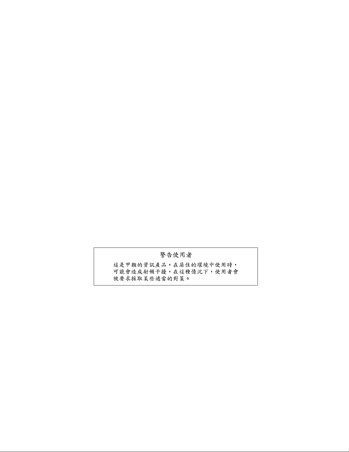
Figure 1-1: IPPC-9120 front view ...............................................................7
Figure 1-2: IPPC-9150 front view ...............................................................7
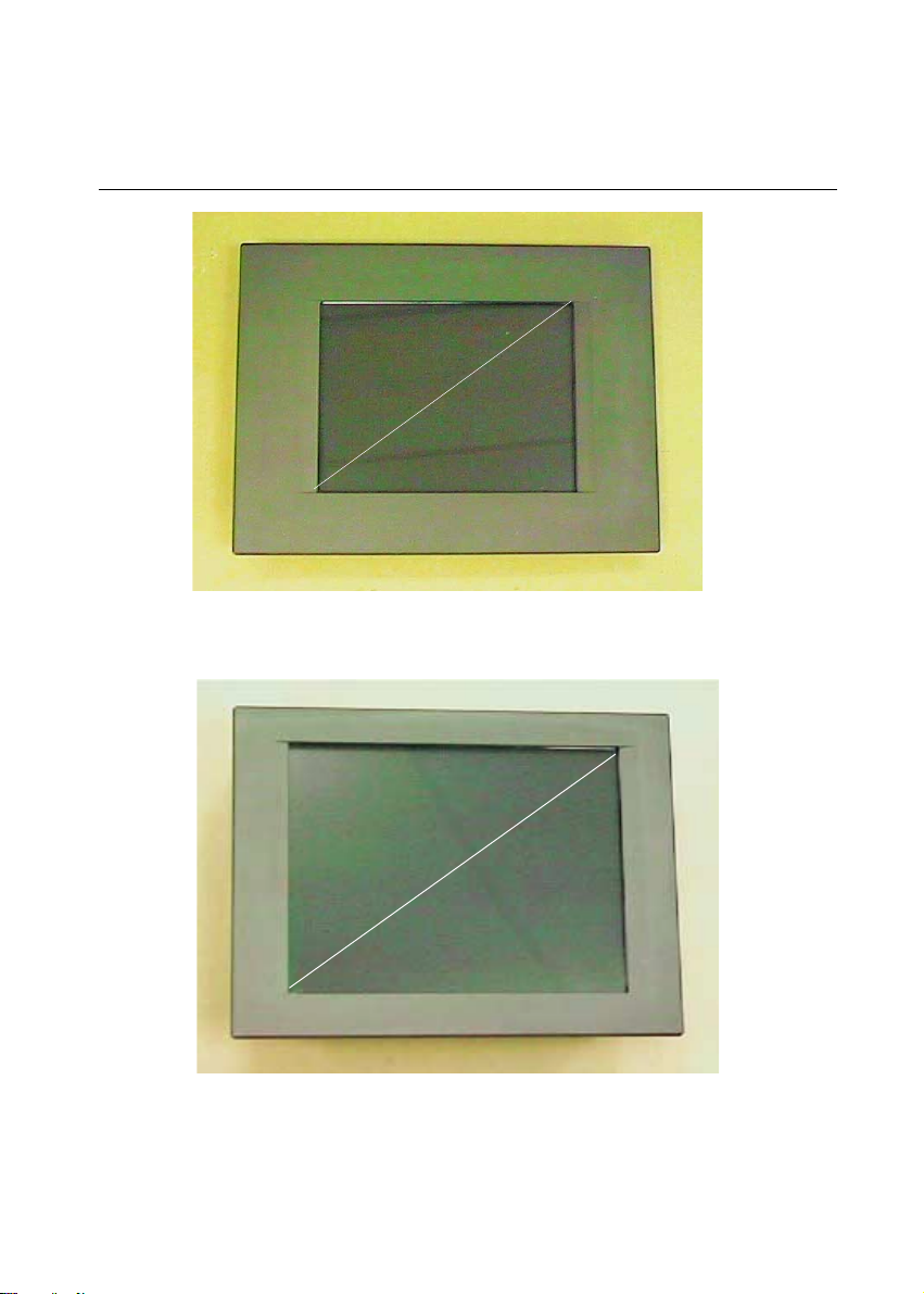
Figure 1-3: IPPC-9120/9150 Series dimensions .........................................8
Figure 2-1: Side view .............................................................................. 11
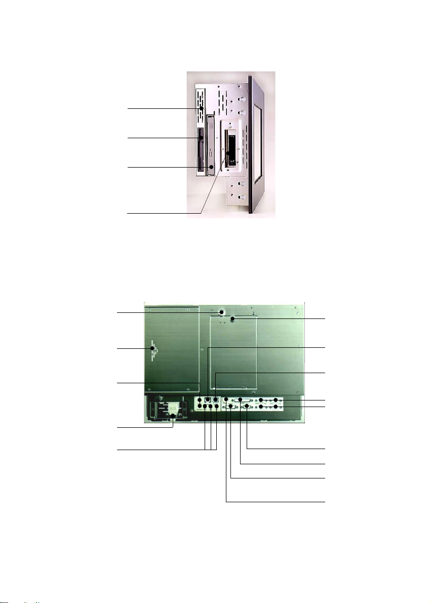
Figure 2-2: Rear view ..............................................................................11
Figure 2-3: Installing SDRAM ................................................................. 15
Figure 2-4: Installing a CPU ................................................................... 17
Figure 2-5: Removing the back case screws ............................................ 19
Figure 2-6: Removing the HDD/FDD bracket screws ................................. 20
Figure 2-7: Assembling the HDD ............................................................ 21
Figure 2-8: Removing the back case screws ............................................ 22
Figure 2-9: Attaching the connector to the CD-ROM ................................. 22
Figure 2-10: Installing an add-on card...................................................... 23
Figure 2-11: Panel mounting................................................................... 25
Figure 2-12: Mounting the IPPC-9120/9150 Series into a frame ................. 26
Figure 2-13: Mounting the IPPC-9120/9150 Series and
frame assembly into a rack ................................................ 27
Figure 3-1: Locating jumpers on the IPPC-9120/9150 motherboard ............ 32
Figure 3-2: Locating connectors on the IPPC-9120/9150 motherboard ........ 34
Figure 9-1: Setup program initial screen ................................................. 106
Figure 9-2: CMOS setup screen ............................................................ 107
Figure 9-3: BIOS features setup screen.................................................. 109
Figure 9-4: Chipset features setup screen ..............................................113
Figure 9-5: Power management setup screen .........................................115
Figure 9-6: PNP/PCI configuration setup screen......................................118
Figure 9-7: Load BIOS defaults screen ................................................... 119
Figure 9-8: Integrated peripherals screen ................................................120
Figure 9-9: IDE HDD auto detection screen ............................................ 123
Figure 9-10: Save and exit setup screen................................................. 124
Page 15

Tables
Table 3-1: Jumpers and their functions .................................................31
Table 3-2: Panel PC connectors ..........................................................33
Table 3-3: COM2 RS-232/422/485 setting (JP3, JP4) .............................35
Table 3-4: COM2 RS-232/422/485 setting (JP5) .................................... 35
Table 3-5: Serial port default settings ...................................................36
Table 3-6: COM1 / COM2 pin 9 output type setting (JP9) ....................... 36
Table 3-7: COM3/RI pin setting (JP6) ................................................... 37
Table 3-8: Clear CMOS / External RTC (JP8) ........................................ 37
Table 3-9: Internal -12 V source enable setting (JP1) ............................. 38
Table 1: Panel type select (SW3) ........................................................ 39
Table 3-11: Watchdog activity selection (JP7) ....................................... 39
Table A-1: IPPC-9120/9150 Series LCD specifications .........................126
TableCD-1: AT power connector (J1)...................................................132
Table C-2: TV output connector (J2) ...................................................132
Table C-3: Inverter power connector (J4) .............................................133
Table C-4: Internal speaker connector (J6) ..........................................133
Table C-5: Front panel control connector (J8) (*Reserved).....................134
Table C-6: IR connector (J9) (Reserved) .............................................. 134
Table C-7: Flat panel display connector (CN2).....................................135
Table C-8: Flat panel display connector (CN3).....................................136
Table C-9: PanelLink Interface (CN4) (*Reserved) ................................137
Table C-10: Floppy drive connector (CN10) .........................................138
Table C-11: Internal COM4, mouse and touch screen................................
power connector (CN23) ................................................139
Table C-12: EIDE hard disk drive connector (CN16) .............................140
Table C-13: CD-ROM connector (CN18)..............................................141
Table C-14: CPU fan power connector (FAN1) .....................................142
Table C-15: Fan power connector (FAN2)............................................142
Table C-16: PCI/ISA slot pin assignments (Pins A and B) .................... 144
Table C-17: PCI/ISA slot pin assignments (Pins C and D) ....................145
Table C-18: PCI/ISA slot pin assignments (Pins E and F) ....................146
Table C-19: PCI/ISA slot pin assignments (Pins G and H) .................... 147
Table C-20: COM2.............................................................................148
Page 16

CHAPTER
General Information
• Introduction
• Specifications
• Dimensions
1
Page 17

1.1 Introduction
The IPPC-9120/9150 series industrial panel PC is specially designed to fit in
space-limited environments where expansion is restricted. Its solid structure
enables the system to operate under harsh industrial conditions.
Sturdy structure
The whole system is protected by a firm solid structure. The front panel is
made of sturdy aluminum and has strengthened glass. It is shock resistant,
and complies with NEMA4/IP65. The stainless steel case (SUS304) on the
rear side is rugged and corrosion resistant, and enables the system to operate
reliably in even the harshest of environments.
Easy maintenance
A back door with lock is located right above the motherboard. Thus users can
easily maintain the CPU, HDD, SDRAM, FDD and CD-ROM drive. Jumpers
can be easily set without removing a single screw. The lock protects the
system from intruders.
Economical system
The PCM-9571B motherboard has Socket 370 architecture. It supports
Pentium® III up to 850 MHz and Celeron™ up to 700MHz. Socket 370 is an
economical yet powerful system. Its reliability enables the system to operate
faultlessly in industrial environments.
Friendly HMI
The IPPC-9120/9150 Series is equipped with a 12.1"/15" LCD, which
provides high resolution display quality (IPPC-9120: 800 x 600; IPPC-9150:
1024 x 768). The result is vivid, bright, and sharp quality images. The IPPC9120/9150 Series is perfectly suited for "Windows" OSs. The touschscreen
version enables simple operation, making the IPPC-9120/9150 Series the
premier industrial digital controller interface.
2
IPPC-9120/9150 Series User's Manual
Page 18

1.2 Specifications
General
• Dimensions (W x H x D):
405 x 302 x 127 mm (15.94" x 11.88" x 5")
• Weight: 10 kg (22 lb)
• Power supply: 80 watts
Input voltage: 115 V AC / 3 A ~ 230 V AC / 1.5 A @ 47 ~ 63 Hz
Output voltage: +5 V @ 12 A, +12 V @ 1 A
• Cooling fan dimensions (W x H x D):
60 x 60 x 10 mm (2.36" x 2.36" x 0.39")
• Disk drive housing: Supports one 2.5" HDD, one slim size CD-ROM
drive, and one slim type FDD
• Chassis: Aluminum front frame complies with NEMA4/IP65. SUS304
stainless steel back case
Standard PC functions
• CPU: Socket 370 Pentium® III up to 850 MHz;
Celeron™ up to 700 MHz
• BIOS: Award 256 KB Flash BIOS
• Chipset: 82443BX/82371EB
• 2nd level cache: 256 KB CPU full-speed cache
• RAM:
One 168-pin DIMM socket accepts 32 ~ 256 MB SDRAM (3.3 V)
• PCI bus master IDE interface: Supports two connectors. Each connector
has one channel and supports two IDE devices. Each channel supports PIO
modes 0 ~ 4, DMA modes 0 ~ 2, and Ultra DMA 33 simultaneously. The
secondary connector is designated for the CD-ROM drive. BIOS supports
IDE CD-ROM boot-up.
• Parallel port: One parallel port, supports SPP/EPP/ECP parallel mode.
BIOS configurable to LPT1, LPT2, LPT3 or disabled
Chapter 1 General Information
3
Page 19

• Serial ports: Four serial ports with three RS-232 ports (COM1, COM3, and
*COM4) and one RS-232/422/485 port (COM2). All ports are compatible
with 16C550 UARTs
• Universal serial bus (USB) port: Supports up to two USB ports
• PCI/ISA bus expansion slot:
Accepts either two PCI cards or one ISA/one PCI bus card
• Watchdog timer: 63-level, interval 1 ~ 63 seconds.
Automatically generates system reset or IRQ11 when the system stops due
to a program error or EMI. Jumperless selection and software enabled/
disabled
• Battery: 3.0 V @ 195 mA lithium battery
PCI SVGA/flat panel interface
• Chipset: Silicon Motion® Lynx3DM8
• Display memory: 8 MB on-die memory
• Display type: Simultaneously supports CRT and flat panel displays (TFT
and DSTN)
• Display resolution: Supports non-interlaced CRT and LCD displays up to
1600x 1200
Audio function
• Chipset: ESS 1946S
• Audio controller:
16-bit codec, full-duplex stereo single-chip audio solution
• Stereo sound: 100% DOS game compatible (Sound Blaster or Sound
Blaster Pro)
• Audio interface: Microphone-in, line-in, line-out, and game ports
* Warning: COM port 4 on the IPPC-9120T-T, IPPC-9150T-T and
IPPC-9150T-N models is reserved for a touchscreen only.
Improper use of this COM port will cause system failure.
4
IPPC-9120/9150 Series User's Manual
Page 20

PCI bus Ethernet interface
• Chipset: Realtek RTL 8139 PCI local bus Ethernet controller
• Ethernet interface: Fully complies with IEEE 802.3u 100Base-T and 10 Base-
T specifications. Includes software drivers and boot ROM
• 100/10Base-T auto-sensing capability
Analog Resistive Touchscreen (optional)
• Type: Analog resistive
• Resolution: Continuous
• Light transmission:
72% (surface meets ASTM-D-3363-92A standard, Taber abrasion test)
• Controller: RS-232 interface (uses COM4)
• Power consumption: +5 V @ 200 mA
• Software driver: Supports DOS, Windows 3.1, Windows 95/98/2000/ME
and Windows NT 4.0
NFI Touchscreen (optional)
• Resolution: 1024 per axis
• Light transmission: >82%
• Controller: RS-232 interface (uses COM4)
• Power consumption: +5 V @ 150 mA
• Software driver: Supports DOS, Windows 3.1, Windows 95/98, Windows
NT 4.0
Optional modules
• IPPC-9150 Stand: stand kit for IPPC-9150/9120 series products
• IPPC-9150 S-ARM: swing arm for IPPC-9150/9120 series
• IPPC-9150 Rack-MT: 19" rank mounint kit for IPPC-9150/9120 series
• CDR-9150-24X: 24x CD-ROM kit for IPPC-9150/9120 series
Chapter 1 General Information
5
Page 21

Environmental
• Operating temperature: 0° ~ 50° C (32° ~ 122° F)
• Storage temperature: -20° ~ 60° C (-4° ~ 140° F)
• Relative humidity: 10 ~ 90% @ 40°
C (non-condensing)
• Shock: 30 G peak acceleration (11 ms duration)
• Power MTBF: 100,000 hrs
• Certification: CE, FCC Class A; meets UL, BSMI
6
IPPC-9120/9150 Series User's Manual
Page 22
1.3 Dimensions
Figure 1-1: IPPC-9120 front view
12"
15"
Figure 1-2: IPPC-9150 front view
Chapter 1 General Information
7
Page 23
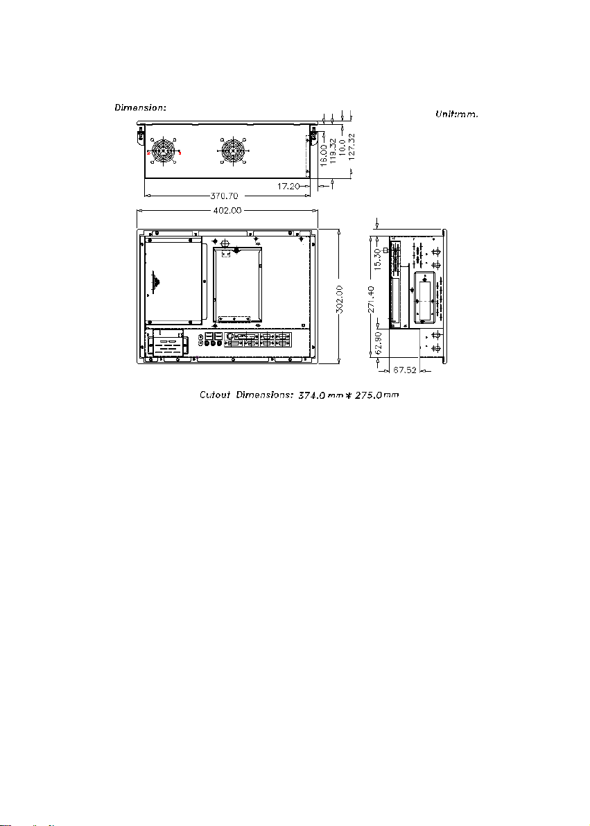
Figure 1-3: IPPC-9120/9150 Series dimensions
8
IPPC-9120/9150 Series User's Manual
Page 24

System Setup
• General
• Installing SDRAM
• Installing a CPU
• Installing a 2.5" HDD
• Installing a CD-ROM Drive
• Installing Add-on Cards
• Mounting Instructions
CHAPTER
2
Page 25

2.1 A Quick Tour of the IPPC-9120/9150 Series
Before you start the computer, please follow these procedures to set up the
system.
1. Check and adjusting jumpers on the motherboard (refer to Chapter 3)
2. Installing SDRAM
3. Installing a CPU
4. Installing add-on cards
5. Connect the wires, cables and accessories
6. Mounting the computer
7. Programming BIOS settings
8. Installing an operating system
Warnings: 1. Every time you access the interior of the computer,
please switch it off and unplug it.
2. The motherboard inside the system is composed of man y
delicate ICs, chips and other integrated circuit components.
These components are easily damaged by static shock.
When you begin to install components, please:
Av oid touching metal parts of the motherboard.
Wear an anti-static ring when handling a CPU or SDRAM
module.
Put SDRAM modules and the CPU inside an anti-static bag
or similar place before installation.
10
IPPC-9120/9150 Series User's Manual
Page 26
2.5" HDD
Slim type
1.44 MB FDD
Slim type 24X
CD-ROM
drive
PCMICA
Figure 2-1: Side view
Back door lock
Add-on card
bay cover
Brightness control
Power cord
security clamp
Audio ports
Figure 2-2: Rear view
Back door knob
Ethernet
Two USB
ports
Four COM
ports
VGA port
Parallel port
Game port
PS/2 keyboard
connector
Chapter 2 System Setup
11
Page 27

2.1.1 PS/2 mouse and keyboard
If you wish to use a full-size desktop keyboard and PS/2 mouse with your
panel PC, follow these instructions:
1. Be sure the panel PC is turned off.
2. Connect the Y-shaped adapter to the PS/2 mouse and keyboard port on
the rear bottom side of the rear cover.
3. Attach the keyboard to the 5-pin port of the Y-shaped adapter.
4. Attach the PS/2 mouse to the 6-pin female PS/2 port of the Y-shaped
adapter.
5. Turn on the panel PC.
2.1.2 Parallel port
The panel PC supports the latest EPP and ECP parallel port protocols for
improved performance and versatility with compatible printers or other
devices.
To connect the panel PC to a printer or other devices:
1. Make sure both the panel PC and the printer/devices are turned off.
2. Connect the 25-pin male connector of the printer cable to the 25-pin female
port on the panel PC labelled "parallel port."
3. If necessary, attach the other end of your printer cable to your printer, and
fasten any retaining screws.
4. Turn on the printer and any other peripheral devices you may have
connected to the panel PC. Then turn on the panel PC.
5. If necessary, run the panel PC's BIOS setup program to configure the
parallel port to respond as required by your printer and software operating
environment.
12
IPPC-9120/9150 Series User's Manual
Page 28

2.1.3 Serial COM ports
There are four serial COM ports on the bottom of the rear cover. You can
easily attach a serial device to the panel PC, such as an external modem or
mouse. Follow these instructions:
1. Make sure the panel PC and any other peripherial devices you may have
connected to the panel PC are turned off.
2. Attach the interface cable of the serial device to the panel PC's serial port.
(See Fig. 2-2.) If necessary, attach the other end of the interface cable to
your serial device. Fasten any retaining screws.
3. Turn on any other peripheral devices you may have connected to the
panel PC, and then turn on the panel PC.
4. Refer to the manual(s) which accompanied your serial device(s) for
instructions on configuring your operating environment to recognize the
device(s).
5. Run the BIOS setup program to set the I/O address and IRQ, and configure the jumper settings to change the mode of the COM ports (refer to
section 3.3).
2.1.4 VGA port
An external VGA-compatible device may be connected to the system via the
15-pin external port located on the rear of the system unit. The panel PC
simultaneously supports an external CRT monitor in addition to its own LCD
display.
1. Make sure the panel PC is turned off.
2. Connect the external monitor to the system.
3. Turn on the panel PC and the external monitor.
Chapter 2 System Setup
13
Page 29

2.1.5 USB ports
An external USB device may be connected to the system via the 4-pin USB
ports located on the rear side of the system unit.
1. Connect the external device to the system.
2. The USB ports support hot plug-in connection. You should install the
device driver before you use the device.
2.1.6 Audio interface
The audio interface includes three jacks: microphone-in, line-out and line-in.
Their functions are:
Microphone-in: Use an external microphone to record voice and sound.
Line-out: Output audio to external devices such as speakers or earphones.
The built-in speaker will not be disabled when the line-out jack is connected
to external audio devices.
Line-in: Input audio from an external CD player or radio.
1. Connect the audio device to the system.
2. Install the driver before you use the device.
2.1.7 Ethernet
To install the Ethernet to your system:
1. Make sure the panel PC is turned off.
2. Connect the Ethernet cable.
3. Turn on the panel PC.
4. Under DOS,run D:\IPPC9150&9120\LAN\RSET8139.EXE to
check hardware network status before installing the Ethernet driver.
5. Run the Ethernet driver to connect up to the network.
2.1.8 Adjusting the LCD brightness
The brightness control knob allows you to adjust the brightness of the LCD
display panel.
14
IPPC-9120/9150 Series User's Manual
Page 30
2.2 Installing SDRAM
You can install from 32 to 256 MB of SDRAM memory. The panel PC system
provides one 168-pin DIMM (Double Inline Memory Module) socket, and
supports 3.3 V SDRAM with a minimum speed of 12 ns.
1. Unlock the back door and open it.
2. Push the two white eject levers on each side of the DIMM outward until
they are separated from the black vertical posts.
3. Insert the memory module into the socket at an angle of 90 degrees.
4. Push the two eject levers toward the vertical posts at each end of the
socket until the module is upright.
Figure 2-3: Installing SDRAM
Chapter 2 System Setup
15
Page 31

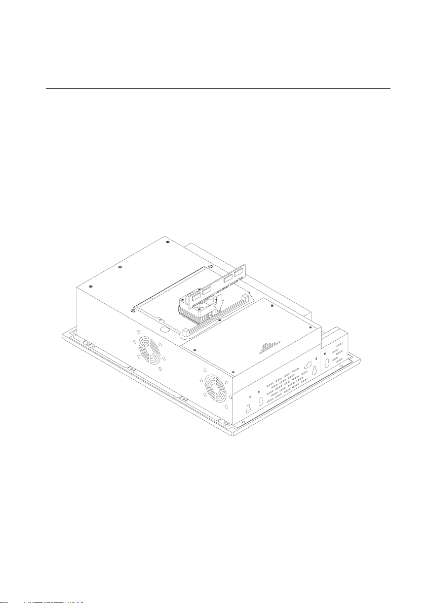
2.3 Installing a CPU
The CPU can be upgraded to improve system performance. The system
provides Socket 370 architecture which supports Pentium® III CPU up to 850
MHz, Celeron™ up to 700 MHz.
Warning: Always disconnect the power cord from your panel PC
when you are working on it. Do not make connections while
the power is on, because sensitive electronic components
can be damaged by the sudden rush of power . Only e xperienced electronics personnel should open the panel PC.
1. Unlock the back door and open it.
2. The CPU board will auto-detect CPU's voltage and frequency; there are no
jumper settings.
3. Open the CPU socket by pulling up the lever sideways from the socket,
then upwards at an angle of 90 degrees.
4. Insert the CPU with the correct orientation. The notched corner of the
CPU (with the white dot) should point toward the end of the lever. The
end of the lever is the blank area where one hole is missing from the corner
of the square array of pin holes. An arrowhead printed on the motherboard points to the end of the lever.
5. Slide the CPU in gently. It should insert easily. If not, pull the lever up a
little more and make sure the pins of the CPU correspond with the holes of
the socket. DO NOT USE EXCESSIVE FORCE!
6. Press the lever down. The plate will slide forward.
7. Place the heat sink on top of the CPU, and secure it with the heat sink clip.
8. Connect the CPU's cooling fan power connector.
16
IPPC-9120/9150 Series User's Manual
Page 32

Figure 2-4: Installing a CPU
Chapter 2 System Setup
17
Page 33

2.4 Installing a 2.5" HDD
The system supports one 2.5" slim type IDE HDD. The IDE controller, which
uses a PCI local bus interface, allows the HDD to exceed 528 MB.
When installing an HDD, follow these steps:
1. Unlock the back door and open it.
2. Unscrew the bolt in the center of the HDD-FDD bracket.
3. Detach the FDD flat cable.
4. Remove the five screws on the back case (see Fig. 2-5).
5. Take out the HDD-FDD bracket.
6. Remove the four screws in the bottom of the HDD-FDD bracket (see Fig.
2-6).
7. There are two HDD support assemblies. Unscrew the two screws on the
side of each HDD support assembly.
8. Mount the HDD support assemblies, one on each side of the HDD.
9. Fasten the four screws in the bottom of the HDD-FDD bracket (see Fig. 2-
6).
10. Put in the HDD-FDD bracket.
11. Fasten the five screws on the back case (see Fig. 2-5).
12. Attach the FDD flat cable.
13. Fasten the bolt in the center of the HDD-FDD bracket.
14. Close the back door and lock it.
18
IPPC-9120/9150 Series User's Manual
Page 34

Figure 2-5: Removing the back case screws
Chapter 2 System Setup
19
Page 35

Figure 2-6: Removing the HDD/FDD bracket screws
20
IPPC-9120/9150 Series User's Manual
Page 36

Figure 2-7: Assembling the HDD
2.5 Installing a CD-ROM Drive
One slim type CD-ROM drive can be installed in the system. Before installing
the CD-ROM drive, take out the FDD-HDD bay. (Refer to Section 2.4)
1. Remove the three screws on the bottom of back case (see Fig. 2-8).
2. Pull out the drive bay cage, and attach the CD-ROM drive's cable to
connector CN18 on the motherboard.
3. Install "CDR-9150-24X" into the drive bay by inserting it directly into the
end. Then attach the cable to the CD-ROM drive.
4. The securing ("fix") clip is located on back of the CDR-9150-24X. Move
the short arm of the clip so that the lug at its end engages into the hole in
the long arm of the clip. Then press the connector tightly onto the CDROM. (See Fig. 2-9.)
Chapter 2 System Setup
21
Page 37

Figure 2-8: Removing the back case screws
Figure 2-9: Attaching the connector to the CD-ROM
22
IPPC-9120/9150 Series User's Manual
Page 38

2.6 Installing Add-on Cards
This system supports two PCI cards or one PCI and one ISA expansion card.
1. Detach the five screws on the back to open the lid.
2. Take away the adapter bracket by detaching the screw which is mounted
in the little box (see Fig. 2-10).
3. Insert the add-on card, and put on the lid.
Figure 2-10: Installing an add-on card
Chapter 2 System Setup
23
Page 39

2.7 Mounting Instructions
There are two ways to mount the system: panel mounting or rack mounting.
2.7.1 Panel mounting
1. Take the four mounting brackets out of the accessory box.
2. Attach the four mounting brackets by inserting the screws into the
keyhole slots on the cover of the monitor.
3. Use the screws to secure the brackets to the cover. Tighten the screws to
secure the monitor to the back panel.
24
IPPC-9120/9150 Series User's Manual
Page 40

Figure 2-11: Panel mounting
Chapter 2 System Setup
25
Page 41

2.7.2 Rack mounting
The monitor can be mounted to a 19" industrial rack. Please order the optional
bracket "IPPC-9150 Rack-MT".
Mount the monitor to the bracket by following the instructions in Section
2.7.1 on the previous page. Then attach the bracket with the monitor to the
19" industrial rack. (See Fig. 2-12.)
Figure 2-12: Mounting the IPPC-9120/9150 Series into a frame
26
IPPC-9120/9150 Series User's Manual
Page 42

Figure 2-13: Mounting the IPPC-9120/9150 Series and frame assembly into a
rack
Chapter 2 System Setup
27
Page 43

28
IPPC-9120/9150 Series User's Manual
Page 44

CHAPTER
3
Jumper Settings and
Connectors
This chapter tells how to set up the panel
PC hardware, including instructions on
setting jumpers and connecting peripherals,
switches and indicators. Be sure to read
all the safety precautions before you
begin the installation procedures.
• Jumpers and Connectors
• CPU Installation
• CMOS Clear for External RTC (JP8)
• COM-port Interface
• Internal -12 V Source Selection Setting
(JP1)
• VGA Interface
• Watchdog Timer Configuration
Page 45

3.1 Jumpers and Connectors
3.1.1 Setting jumpers
You can configure your panel PC to match the needs of your application by setting jumpers. A jumper is the simplest kind of electrical
switch. It consists of two metal pins and a small metal clip (often
protected by a plastic cover) that slides over the pins to connect them.
To “close” a jumper, you connect the pins with the clip. To “open” a
jumper you remove the clip. Sometimes a jumper will have three pins,
labeled 1, 2, and 3. In this case, you would connect either pins 1 and 2
or pins 2 and 3.
2
1
3
OpenOpen
Open
OpenOpen
ClosedClosed
Closed
ClosedClosed
Closed 2 - 3Closed 2 - 3
Closed 2 - 3
Closed 2 - 3Closed 2 - 3
The jumper settings are schematically depicted in this manual as
follows:
1
OpenOpen
Open
OpenOpen
ClosedClosed
Closed
ClosedClosed
Closed 2 - 3Closed 2 - 3
Closed 2 - 3
Closed 2 - 3Closed 2 - 3
A pair of needle-nose pliers may be helpful when working with
jumpers.
If you have any doubts about the best hardware configuration for
your application, contact your local distributor or sales representative
before you make any changes.
30
IPPC-9120/9150 Series User's Manual
Page 46

3.1.2 Jumpers and switch
The motherboard of the IPPC-9120/9150 has a number of jumpers that
allow you to configure your system to suit your applications. The
table below lists the function of each of the board’s jumpers.
Table 3-1: Jumpers and their functions
Label Function
JP1 Internal -12 V source selection setting
JP2 Wake on LAN (not used for IPPC-9120/9150)
JP3 COM2 RS-232/422/485 setting
JP4 COM2 RS-232/422/485 setting
JP5 COM2 RS-232/422/485 setting
JP6 COM3 / COM4 Pin 9 output type setting
JP7 Watchdog timer action
JP8 CMOS clear for external RTC
JP9 COM1 / COM2 Pin 9 output type setting
SW3 Panel type setting
Chapter 3 Jumper Settings and Connectors
31
Page 47

JP2: Wake on LAN
(Reserved)
3.1.3 Locating jumpers and switch
JP7: Watchdog
timer action
JP8: CMOS clear
for external RTC
JP1: Internal -12 V
source enable
setting
SW3: Panel type
setting
JP6: COM3 / COM4
Pin 9 output type
JP9: COM1 / COM2
Pin 9 output type
setting
setting
Figure 3-1: Locating jumpers on the IPPC-9120/9150 motherboard
32
IPPC-9120/9150 Series User's Manual
JP3: COM2
RS-232/422/485
setting
JP4: COM2
RS-232/422/485
setting
JP5: COM2
RS-232/422/485
setting
Page 48

3.1.4 Connectors
Onboard connectors link the panel PC to external devices such as hard
disk drives or floppy drives. The table below lists the function of each
of the board’s connectors.
Table 3-2: Panel PC connectors
Label Function
J1 AT power connector
J4 Inverter power connector
J6 Internal speaker connector (Reserved)
J8 Front panel control connector (Reserved)
J9 IR connector (Reserved)
CN2 Flat panel display connector
CN3 Flat panel display connector
CN4 PanelLink interface (Reserved)
CN10 FDD connector
CN23 Internal COM4, mouse and touchscreen
power connector
CN16 EIDE hard disk drive connector
CN18 CD-ROM connector
FAN1 CPU fan power connector
FAN2 System fan power connector
SLOT1 PCI/ISA bus expansion connector
Chapter 3 Jumper Settings and Connectors
33
Page 49

3.1.5 Locating connectors
FAN2: System fan
power connector
J4: Inverter power
connector
J6: Internal
speaker connector
(Reserved)
FAN1: CPU fan
power connector
CN10: Floppy
drive connector
J9: IR connector
(Reserved)
CN23: Internal COM4,
mouse, and touchscreen
power connector
J8: Front panel
control connector
(Reserved)
J1: AT power
connector
SLOT1: PCI/ISA
expansion
connector
CN16: EIDE
hard disk drive
connector
CN18: CD-ROM
connector
CN4: PanelLink
interface
(Reserved)
CN2: Flat panel
display
connector
CN3: Flat panel
display
connector
Figure 3-2: Locating connectors on the IPPC-9120/9150 motherboard
34
IPPC-9120/9150 Series User's Manual
Page 50

3.2 CPU Installation
You can install a Pentium® III CPU up to 850 MHz or Celeron ™ CPU
up to 700 without setting any frequency ratio or voltage.
3.3 COM-port Interface
The IPPC-9120/9150 provides four serial ports (COM1, 3, 4: RS-232;
COM2: RS-232/422/485) in one COM port connector.
3.3.1 COM2 RS-232/422/485 setting (JP3, JP4, JP5)
COM2 can be configured to operate in RS-232, RS-422, or RS-485
mode. This is done via JP3, JP4 and JP5.
Table 3-3: COM2 RS-232/422/485 setting (JP3, JP4)
*RS-232 RS-422/485
26
JP4
15
26
JP3
15
JP4
JP3
26
15
26
15
* default setting
Table 3-4: COM2 RS-232/422/485 setting (JP5)
*RS-232 RS-422 RS-485
246
135
246
135
246
135
* default setting
The IRQ and the address ranges for COM1, 2, 3, and 4 are fixed.
Chapter 3 Jumper Settings and Connectors
35
Page 51

However, if you wish to disable the port or change these parameters
later you can do this in the system BIOS setup. The table overleaf
shows the default settings for the panel PC’s serial ports.
COM1 and COM2 are one set. You can exchange the address range
and interrupt IRQ of COM1 for the address range and interrupt IRQ of
COM2. After exchanging, COM1's address range is 2F8 ~ 2FF and its
request IRQ is IRQ3: and COM2's address range is 3F8 ~ 3FF and its
interrupt IRQ is IRQ4.
COM3 and COM4 are another set. Their selectable function is the
same as the COM1/COM2 set.
Table 3-5: Serial port default settings
Port Address Range Interrupt
COM1 3F8 ~ 3FF IRQ4
COM2 2F8 ~ 2FF IRQ3
COM3 3E8 ~ 3EF IRQ10
COM4 2E8 ~ 2EF IRQ5
3.3.2 COM1 / COM2 pin 9 output type setting (JP9)
Table 3-6: COM1 / COM2 pin 9 output type setting (JP9)
*Normal operation +5 V output +12 V output
6
4
2
5
3
1
6
4
2
* default setting
Note: Pins 1, 3 and 5 are for COM1.
Pins 2, 4 and 6 are for COM2.
36
IPPC-9120/9150 Series User's Manual
5
3
1
6
4
2
5
3
1
Page 52

3.3.3 COM3 / COM4 pin 9 output type setting (JP6)
Table 3-7: COM3/RI pin setting (JP6)
*Normal operation +5 V output +12 V output
6
4
2
5
3
1
6
4
2
5
3
1
6
4
2
5
3
1
* default setting
Note: Pins 1, 3 and 5 are for COM3.
Pins 2, 4 and 6 are for COM4.
3.4 CMOS Clear for External RTC (JP8)
Warning: To avoid damaging the computer , alwa ys turn off the
power supply before setting “Clear CMOS”. Set the
jumper back to “Normal operation” before turning on
the power supply.
Table 3-8: Clear CMOS / External RTC (JP8)
*Normal operation Clear CMOS
12 12
* default setting
Chapter 3 Jumper Settings and Connectors
37
Page 53

3.5 Internal -12 V Source Enable Setting
(JP1)
The panel PC provides an internal -12 V source to the expansion slots.
Table 3-9: Internal -12 V source enable setting (JP1)
* Enable -12 V support Disable -12 V support
1 2 1 2
* default setting
3.6 VGA Interface
The Panel PC's AGP VGA interface can drive conventional CRT
displays. It is also capable of driving TFT and DSTN LCD displays.
The board has two connectors to support these displays simultaneously: one for standard CRT VGA monitors, and one for flat panel
displays.
CRT display port information can be found in Section 2.1.4.
Pin assignments for the flat panel display connector, backlight
connector and other related connectors are shown in Appendix C.
3.6.1 LCD panel power setting
The panel PC's AGP SVGA interface supports 5 V and 3.3 V LCD
displays. The LCD cable already has a built-in default setting. You do
not need to adjust any jumper or switch to select the panel power.
3.6.2 Panel type select (SW3)
SW3 is an 8-pin dip switch for selecting panel type and display mode.
The 800 x 600 and 1024 x 768 TFT LCDs are used in the IPPC-9120
and IPPC-9150 respectively, so the switch is preset according to the
table below. The switch is already defaulted for the IPPC-9120 and
IPPC-9150’s LCDs, so it should not be modified. If you require modifi-
38 IPPC-9120/9150 Series User's Manual
Page 54

cation for a special purpose, we recommend that you consult your
distributor or our sales representative for detailed information.
Table 3-10: Panel type select (SW3)
Panel type Pin1 Pin2 Pin3 Pin4 Pin5 Pin6 Pin7 Pin8
800 x 600 ON ON OFF ON ON OFF ON ON
1024 x 768
(36-bit) ON ON ON OFF ON OFF OFF ON
1024 x 768
(48-bit) ON ON ON OFF OFF OFF OFF ON
3.7 Watchdog Timer Configuration
An onboard watchdog timer reduces the chance of disruptions which
EMP (electromagnetic pulse) interference can cause. This is an
invaluable protective device for standalone or unmanned applications.
Setup involves one jumper and running the control software. (Refer to
Appendix B.)
3.7.1 Watchdog activity selection (JP7)
When the watchdog timer activates (i.e. CPU processing has come to a
halt), it can reset the system or generate an interrupt on IRQ11. This
can be set via jumper JP7 as shown below:
Table 3-11: Watchdog activity selection (JP7)
*System reset IRQ11
1
* default setting
Chapter 3 Jumper Settings and Connectors 39
1
Page 55

40
IPPC-9120/9150 Series User's Manual
Page 56

CHAPTER
4
PCI Bus Ethernet
Interface
This chapter provides information on
Ethernet configuration.
• Introduction
• Installation of Ethernet Driver
- for Windows 95
- for Windows 98
- for Windows NT
• Further Information
Page 57

4.1 Introduction
The IPPC-9120/9150 is equipped with a high performance 32-bit
Ethernet chipset which is fully compliant with IEEE 802.3 100 Mbps
CSMA/CD standards. It is supported by major network operating
systems. It is also both 100Base-T and 10Base-T compatible. The
medium type can be configured via the RSET8139.exe program
included on the utility disk.
The Ethernet port provides a standard RJ-45 jack. The network boot
feature can be utilized by incorporating the boot ROM image files for
the appropriate network operating system. The boot ROM BIOS files
are combined with system BIOS, which can be enabled/disabled in
the BIOS setup.
4.2 Installation of Ethernet Driver
Before installing the Ethernet driver, note the procedures below. You
must know which operating system you are using in your IPPC-9120/
9150, and then refer to the corresponding installation flow chart. Then
just follow the steps described in the flow chart. You will quickly and
successfully complete the installation, even if you are not familiar with
instructions for Windows.
Imp ortant : The following windows illustrations are examples
only. You must follow the flow chart instructions
and pay attention to the instructions which then
appear on your screen.
Note 1 : The CD-ROM drive is designated as "D" through-
out this chapter.
Note 2: <Enter> means pressing the "Enter" key on the
keyboard.
42
IPPC-9120/9150 Series User's Manual
Page 58

4.2.1 Installation for Windows 95
1. a. Select "Start," "Settings," "Control Panel," "System"
b. Click "Device Manager" and "Other Devices"
c. Remove "PCI Ethernet Controller" item
2. a. Select "Start," "Settings," "Control Panel" and "Network"
b. Click "Add"
Chapter 4 PCI Bus Ethernet Interface
43
Page 59

3. Select "Adapter" and then "Add"
4. Press the "Have Disk..." button
5. a. Type path "D:\IPPC9150&9120T\Lan\W95OSR2"
b. Click "OK"
44
IPPC-9120/9150 Series User's Manual
Page 60

6. a. Choose "Realtek RTL8139(A/B/C/8130)PCI Fast Ethernet"
b. Press "OK"
7. a. Press "Add..." to select suitable services or protocol
b. Press "OK" to finish network configuration
8. Press "Yes" to reboot your system
Chapter 4 PCI Bus Ethernet Interface
45
Page 61

4.2.2 Installation for Windows 98
1. a. Select "Start," "Settings," "Control Panel," "System"
b. Click "Device Manager" and "Other Devices"
c. Remove "PCI Ethernet Controller" item
2. a. Select "Start," "Settings," "Control Panel" and "Network"
b. Click "Add"
46
IPPC-9120/9150 Series User's Manual
Page 62

3. Select "Adapter" and then "Add"
4. Press the "Have Disk..." button
5. a. Type path "D:\IPPC950&9120T\LAN\WIN98"
b. Click "OK"
Chapter 4 PCI Bus Ethernet Interface
47
Page 63

6. a. Choose "Realtek RTL8139(A/B/C/8130)PCI Fast Ethernet"
b. Press "OK"
7. a. Press "Add..." to select suitable services or protocol
b. Press "OK" to finish network configuration
8. Press "Yes" to reboot your system
48
IPPC-9120/9150 Series User's Manual
Page 64

4.2.3 Installation for Windows NT
1. a. Select "Start," "Settings," "Control Panel" and double click the
"Network" icon
b. Choose "Adapters" tab
c. Click "Add"
2. Press "Have Disk..."
Chapter 4 PCI Bus Ethernet Interface
49
Page 65

3. a. Enter the path "D:\IPPC9150&9120T\LAN\Winnt4"
b. Press "OK"
4. a. Choose "Realtek RTL8139(A/B/C/8130)PCI Fast Ethernet"
b. Press "OK"
5. Choose a suitable RTL8139 Duplex mode for your application
50
IPPC-9120/9150 Series User's Manual
Page 66

6. Finish network configuration and click "OK"
Chapter 4 PCI Bus Ethernet Interface
51
Page 67

4.3 Further Information
Realtek website: www.realtek.com.tw
Advantech websites: www.advantech.com
www.advantech.com.tw
52
IPPC-9120/9150 Series User's Manual
Page 68

PCI SVGA Setup
• Introduction
• Installation of SVGA Driver
- for Windows 95
- for Windows 98
- for Windows NT
• Further Information
CHAPTER
5
Page 69

5.1 Introduction
The IPPC-9120/9150 has an onboard AGP flat panel/VGA interface.
The specifications and features are described as follows:
5.1.1 Chipset
The IPPC-9120/9150 uses a Lynx3DM chipset from Silicon Motion
Inc. for its AGP/SVGA controller. It supports TFT, DSTN flat panel
dispays and conventional analog CRT monitors. The SMI 710 VGA
BIOS supports monochrome LCD, EL, color TFT and STN LCD flat
panel displays. In addition, it also supports interlaced and noninterlaced analog monitors (color and monochrome VGA) in highresolution modes while
maintaining complete IBM VGA compatibility. Digital monitors
(i.e. MDA, CGA, and EGA) are NOT supported. Multiple frequency
(multisync) monitors are handled as if they were analog monitors.
5.1.2 Display memory
With onboard 4 MB display memory, the VGA controller can drive
CRT displays or color panel displays with resolutions up to 1024 x
768 at 16 M colors.
5.1.3 Display types
CRT and panel displays can be used simultaneously. The IPPC-9120/
9150 can be set in one of three configurations: on a CRT, on a flat
panel display, or on both simultaneously. The system is initially set to
simultaneous display mode. If you want to enable the CRT display
only or the flat panel display only, contact Silicon Motion Inc. or our
sales representative for detailed information.
5.2 Installation of SVGA Driver
Complete the following steps to install the SVGA driver. Follow the
procedures in the flow chart that apply to the operating system that
you you are using within your IPPC-9120/9150.
54
IPPC-9120/9150 Series User's Manual
Page 70

Important: The following windows illustrations are examples
only. You must follow the flow chart instructions and
pay attention to the instructions which then appear
on your screen.
Note 1: The CD-ROM drive is designated as "D" throughout
this chapter.
Note 2: <Enter> means pressing the "Enter" key on the
keyboard.
Chapter 5 PCI SVGA Setup
55
Page 71

5.2.1 Installation for Windows 95
1. a. Select "Start," " Settings," "Control Panel," "Display" and
"Settings"
b. Press "Advanced Properties"
2. a. Choose "Adapter" tab
b. Press "Change"
56
IPPC-9120/9150 Series User's Manual
Page 72

3. Press "Have Disk..."
4. Enter the path "D:\IPPC9150&9120T\VGA\Win9x"
5. a. Select highlighted item
b. Click "OK"
Chapter 5 PCI SVGA Setup
57
Page 73

6. a. "Silicon Motion Lynx3DM" appears in the adapter label
b. Click "Apply"
c. Clikc "OK"
7. Press "Yes" to reboot your system
58
IPPC-9120/9150 Series User's Manual
Page 74

5.2.2 Installation for Windows 98
1. a. Select "Start," " Settings," "Control Panel," "Display" and
"Settings"
b. Press "Advanced Properties"
2. a. Choose "Adapter" tab
b. Press "Change
Chapter 5 PCI SVGA Setup
59
Page 75

3. Choose the second option; "Display..."
4. Press "Have Disk..."
5. a. Insert the disk into the CD-ROM drive
b. Enter the path "D:\IPPC9150&9120T\VGA\Win9x"
c. Press "OK"
60
IPPC-9120/9150 Series User's Manual
Page 76

6. a. Select highlighted item
b. Click "OK"
7. a. "Silicon Motion Lynx3DM" appears in the adapter label
b. Click "Apply"
c. Clikc "OK"
7. Press "Yes" to reboot your system
Chapter 5 PCI SVGA Setup
61
Page 77

5.2.3 Installation for Windows NT
Note: Service Pack X (X = 3, 4, 5, 6, ...) must be installed
first before you install the Windows NT VGA driver.
1. a. Select "Start," " Settings," "Control Panel
b. Double click "Display"
2. a. Choose "Settings" tab
b. Press "Display Type"
62
IPPC-9120/9150 Series User's Manual
Page 78

3. Press "Change..."
4. Press "Have Disk..."
5. a. Enter the path "D:\IPPC9150&9120T\VGA\nt4"
b. Press "OK"
Chapter 5 PCI SVGA Setup
63
Page 79

6. a. Select highlighted item
b. Click "OK"
7. Press "Yes" to proceed
8. Press "OK" to reboot
64
IPPC-9120/9150 Series User's Manual
Page 80

5.3 Further Information
For further information about the AGP/SVGA installation in your
IPPC-9120/9150, including driver updates, troubleshooting guides
and FAQ lists, visit the following web resources:
Silicon Motion website: www.siliconmotion.com
Advantech websites: www.advantech.com
www.advantech.com.tw
Chapter 5 PCI SVGA Setup
65
Page 81

66
IPPC-9120/9150 Series User's Manual
Page 82

Audio
• Introduction
• Installation of Audio Driver
- for Windows 95/98
- for Windows NT
CHAPTER
6
Page 83

6.1 Introduction
The IPPC-9120/9150's onboard audio interface provides high-quality
stereo sound and FM music synthesis (ESFM) by using the ES1946S
audio controller from ESS Technology, Inc. The audio interface can
record, compress, and play back voice, sound, and music with a builtin mixer control. The IPPC 9120/9150's onboard audio interface also
supports the Plug and Play (PnP) standard and provides PnP configuration for audio, FM, and MPU-104 logical devices. It is compatible
with Sound Blaster, Sound Blaster Pro version 3.01, voice, and music
functions. The ESFM synthesizer is register compatible with the
OPL3 and has extended capabilities.
6.2 Installation of Audio Driver
Before installing the audio driver, please take note of the procedures
detailed below. You must know which operating system you are using
in your IPPC-9120/9150, and then refer to the corresponding installation flow chart. Just follow the steps in the flow chart. You can
quickly and successfully complete the installation, even though you
are not familiar with instructions for Windows.
Important: The following windows illustrations are examples
only. You must follow the flow chart instructions and
pay attention to the instructions which then appear
on your screen.
Note 1: The CD-ROM drive is designated as "D" throughout
this chapter.
Note 2: <Enter> means pressing the "Enter" key on the
keyboard.
68
IPPC-9120/9150 Series User's Manual
Page 84

6.2.1 Installation for Windows 95/98
1. a. Select "Start" and "Run"
b. Enter the driver path
"D:\IPPC9150&9120T\Audio\Win9x(only)\setup.exe
2. Click "Next" to continue
3. a. Select "Upgrade Drivers"
b. Click "Next"
Chapter 6 Audio
69
Page 85

4. Click "Finish" to restart your computer
5. a. After installation, select "Start," "Settings," "Control Panel" and
"System"
b. Click "Device Manager" tab to confirm installation
70
IPPC-9120/9150 Series User's Manual
Page 86
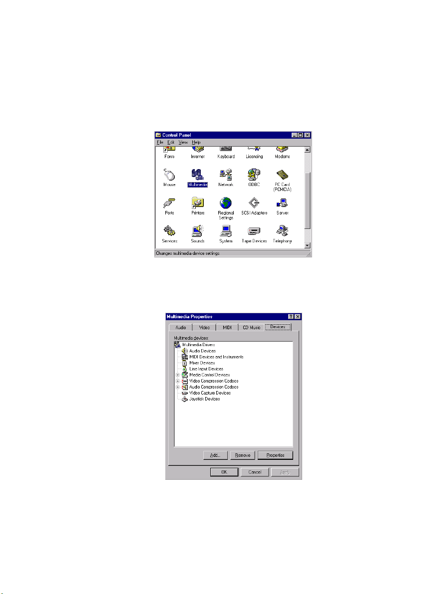
6.2.2 Installation for Windows NT
1. a. Select "Start," "Settings" and "Control Panel"
b. Double click "Multimedia" icon
2. a. Select "Devices" tab
b. Click "Add..."
Chapter 6 Audio
71
Page 87

3. a. Choose "Unlisted or Updated Driver" item
b. Click "OK"
4. a. Enter the path "D:\IPPC9150&9120T\Audio\NT40"
b. Click "OK"
5. a. Select the highlighted item
b. Press "OK"
72
IPPC-9120/9150 Series User's Manual
Page 88

6. Press "Restart Now" to reboot your computer.
Chapter 6 Audio
73
Page 89

74
IPPC-9120/9150 Series User's Manual
Page 90

CHAPTER
PCMCIA
• Introduction
• Installation of PCMCIA Driver
- for Windows 95
7
Page 91

7.1 Introduction
The IPPC-9120/9150 is equipped with a high performance PCMCIA
interface which complies with the 1995 PCMCIA card standard by
using the RICOH Cardbus controller. The panel PC supports two
PCMCIA card/cardbus slots. Two sockets support both a 16-bit
PCMCIA card and a 32-bit Cardbus simultaneously, with hot insertion
and removal.
7.2 Installation of PCMCIA Driver
The PCMCIA driver for Windows 95 is included in the "Drivers and
Utilities" CD-ROM included with your IPPC-9120/9150. The installation
procedure is shown in the next section in this chapter.
Other operating systems such as Windows 98 and Windows NT also
support PCMCIA drivers. However, the drivers for these operating
systems are not included in the "Drivers and Utilities" CD-ROM.
Installation for these operating systems is not explained in this
manual.
Important: The following windows illustrations are examples
only. You must follow the flow chart instructions and
pay attention to the instructions which then appear
on your screen.
Note 1: The CD-ROM drive is designated as "D" throughout
this chapter.
Note 2: <Enter> means pressing the "Enter" key on the
keyboard.
76
IPPC-9120/9150 Series User's Manual
Page 92

7.2.1 Installation for Windows 95
1. a. Select "Start" and "Run"
b. Enter the path
"D:\IPPC9150&9120T\Cardbus\Win95osr2\setup.exe"
2. Click "Next"
Chapter 7 PCMCIA
77
Page 93

3. Click "Yes"
4. Click "Finish" to reboot your system
78
IPPC-9120/9150 Series User's Manual
Page 94

CHAPTER
8
Touchscreen
• Introduction
• Installation of Touchscreen Driver
- for Windows 95
- for Windows 98
- for Windows NT
Page 95

8.1 Introduction
8.1.1 General information
The IPPC-9120/9150 supports analog resistive-type and NFI-type touchscreens. Analog resistive touchscreens are popular and affordable. NFI
offers advantages in exceptional brightness, clarity and readability.
8.1.2 Analog Resistive Touchscreen Specifications
Electrical
• Contact bounce: < 10 ms
• Operating voltage: 5 V (typical)
• Contact current: 20 mA (maximum)
• Circuit resistance (open): > 30 mohms
• Circuit resistance (closed): < 2000 mohms
• Sheet resistance variation: Within one screen: ± 5% nominal
From screen to screen: ± 20% of nominal
Durability
• Test conditions: 4 H hardness, 0.04" stylus pen, 350 gram load
• Point activation:
Single point, position of stylus controlled to ± 0.0005"
Result: > 1 million activations
• Linear activation:
2" diagonal line, position of stylus controlled to ± 0.0005"
Result: > 250,000 cycles
• Chemical resistance:
Hard coating is highly resistant to most solvents and chemicals
Optical
• Visible light transmission: 72% (typical)
• Reflection: > 25% @ 550 nm
Sensor board
• Chemical strengthened glass with 4 H hardness standard.
(Test condition: ASTM D3363-92A)
Ball drop test
• Able to bear a 225 g steel ball dropped from 660 mm elevation without
breaking
Environmental specifications
• Operating pressure: 30 ~ 45 grams for finger; 10 grams for stylus pen
80
IPPC-9120/9150 Series User's Manual
Page 96

• Operating temperature: 0 ~ 50° C (humidity 20 ~ 90% RH)
• Storage temperature: -25 ~ 70° C (humidity 20 ~ 95% RH)
8.1.3 NFI Touchscreen Specifications
Performance
• Touch inputs: gloved hand or bare finger; conductive stylus
• Touch speed: < 20ms nominal controller response time
• Resolution: minimum 1024 points per axis
• Touch positional accuracy: +/- 1.0% in one direction and +/- 2.0% in the
other direction
• Drift: none
Sensor
• Optical Transmissivity: > 83% standard product
• Construction: laminated layers of chemically strengthened glass
• Touch surface: anti-glare glass
Controller
• Communications: RS-232
• Power requirements: 5V +/- 5%, 4.75V minimum ; 150mA average, peaks
to 300mA
• Excitation signal on sensor: 50 to 60Khz 12V p-p
Software
• Dynapro drivers for: MS-DOS, Windows 3.1, Windows 95/98, Windows
NT4.0; support for other operating systems available
• Utilities: set-up and diagnostic utility included
Environmental
• Operating temperature: -20ºC to +70ºC for sensor 0ºC to +70ºC for
controller
• Storage temperature: -40ºC to +85ºC
• Humidity: 95% RH non-condensing
• ESD: exceeds EN 61000-4-2; 8kV air discharge, 4kV contact discharge
• EMI: unaffected by EMI from nearby CRT’s and displays, environmental
EMI; complies with ENV 50140
Reliability
• Touch life: tested to more than 100 million touches in one location
without failure
• Surface durability: equivalent to soda lime glass, Mohs hardness rating
of 6
Chapter 8 Touchscreen
81
Page 97

• Sealing capability: unit can be sealed to protect against splashed
liquids, dirt, and dust; will not prevent NEMA12 and NEMA 4X
• Chemical resistance: resistant to all chemicals that do not affect soda
lime glass; highly resistant to corrosives in accordance with ASTM-D-
1038.
• Impact resistance: meets UL-1950 and CSA C22.2 No. 950 ball drop test;
5kg 50mm diameter ball dropped from height of 1.3m
8.2 Installation of Resistive-type Touchscreen
Driver
The touchscreen built into the IPPC-9120/9150 Series uses a driver for
operating Windows 95, Windows 98, or Windows NT 4.0.
To facilitate installation of the touchscreen driver, you should read the
instructions in this chapter carefully before you attempt installation.
Note 1: The following windo ws illustrations are examples only.
You must follow the flow chart instructions and pay
attention to the instructions which then appear on your
screen.
Note 2: The CD-ROM drive is designated as "D" throughout this
chapter.
82
IPPC-9120/9150 Series User's Manual
Page 98

8.2.1 Installation for Windows 95/98
1. a. Select "Start" and "Run"
b. Enter path
"D:\IPPC9150&9120T\TouchDrv\PenMount\Win9xv3.3\setup.exe"
c. Press OK
2. Select "Advance"
Chapter 8 Touchscreen
83
Page 99

3. Select "I know, I wanna find PenMount right now"
4. After COM4 is found, press "OK" to restart the system
84
IPPC-9120/9150 Series User's Manual
Page 100

5. a.. After system reboot, select "Start," "Programs, "PenMount Utilities"
and "PenMount Control Panel"
b. Press "Calibrate" tab
c. Press "Calibrate" button on the right side
6. a. Use a soft stylus to press the little red dot located above the pointer
b. Repeat the process at the specified locations
Chapter 8 Touchscreen
85
 Loading...