

Page 1

User Manual
FPM-8192V/8232V
19”/23” Marine Grade Monitors
Page 2

Copyright
The documentation and the software included with this product are copyrighted 2008
by Advantech Co., Ltd. All rights are reserved. Advantech Co., Ltd. reserves the right
to make improvements in the products described in this manual at any time without
notice. No part of this manual may be reproduced, copied, translated or transmitted
in any form or by any means without the prior written permission of Advantech Co.,
Ltd. Information provided in this manual is intended to be accurate and reliable. However, Advantech Co., Ltd. assumes no responsibility for its use, nor for any infringements of the rights of third parties, which may result from its use.
Acknowledgements
Intel and Pentium are trademarks of Intel Corporation.
Microsoft Windows and MS-DOS are registered trademarks of Microsoft Corp.
All other product names or trademarks are properties of their respective owners.
Product Warranty (2 years)
Advantech warrants to you, the original purchaser, that each of its products will be
free from defects in materials and workmanship for two years from the date of purchase.
This warranty does not apply to any products which have been repaired or altered by
persons other than repair personnel authorized by Advantech, or which have been
subject to misuse, abuse, accident or improper installation. Advantech assumes no
liability under the terms of this warranty as a consequence of such events.
Because of Advantech’s high quality-control standards and rigorous testing, most of
our customers never need to use our repair service. If an Advantech product is defective, it will be repaired or replaced at no charge during the warranty period. For outof-warranty repairs, you will be billed according to the cost of replacement materials,
service time and freight. Please consult your dealer for more details.
If you think you have a defective product, follow these steps:
1. Collect all the information about the problem encountered. (For example, CPU
speed, Advantech products used, other hardware and software used, etc.) Note
anything abnormal and list any onscreen messages you get when the problem
occurs.
2. Call your dealer and describe the problem. Please have your manual, product,
and any helpful information readily available.
3. If your product is diagnosed as defective, obtain an RMA (return merchandize
authorization) number from your dealer. This allows us to process your return
more quickly.
4. Carefully pack the defective product, a fully-completed Repair and Replacement
Order Card and a photocopy proof of purchase date (such as your sales receipt)
in a shippable container. A product returned without proof of the purchase date
is not eligible for warranty service.
5. Write the RMA number visibly on the outside of the package and ship it prepaid
to your dealer.
Part No.2003819200 Edition 1
Printed in Taiwan December 2008
FPM-8192V/8232V User Manual ii
Page 3

Declaration of Conformity
CE
This product has passed the CE test for environmental specifications when shielded
cables are used for external wiring. We recommend the use of shielded cables. This
kind of cable is available from Advantech. Please contact your local supplier for
ordering information.
CE
This product has passed the CE test for environmental specifications. Test conditions
for passing included the equipment being operated within an industrial enclosure. In
order to protect the product from being damaged by ESD (Electrostatic Discharge)
and EMI leakage, we strongly recommend the use of CE-compliant industrial enclosure products.
FCC Class A
Note: This equipment has been tested and found to comply with the limits for a Class
A digital device, pursuant to part 15 of the FCC Rules. These limits are designed to
provide reasonable protection against harmful interference when the equipment is
operated in a commercial environment. This equipment generates, uses, and can
radiate radio frequency energy and, if not installed and used in accordance with the
instruction manual, may cause harmful interference to radio communications. Operation of this equipment in a residential area is likely to cause harmful interference in
which case the user will be required to correct the interference at his own expense.
FCC Class B
Note: This equipment has been tested and found to comply with the limits for a Class
B digital device, pursuant to part 15 of the FCC Rules. These limits are designed to
provide reasonable protection against harmful interference in a residential installation. This equipment generates, uses and can radiate radio frequency energy and, if
not installed and used in accordance with the instructions, may cause harmful interference to radio communications. However, there is no guarantee that interference
will not occur in a particular installation. If this equipment does cause harmful interference to radio or television reception, which can be determined by turning the equipment off and on, the user is encouraged to try to correct the interference by one or
more of the following measures:
Reorient or relocate the receiving antenna.
Increase the separation between the equipment and receiver.
Connect the equipment into an outlet on a circuit different from that to which the
receiver is connected.
Consult the dealer or an experienced radio/TV technician for help.
FM
This equipment has passed the FM certification. According to the National Fire Protection Association, work sites are classified into different classes, divisions and
groups, based on hazard considerations. This equipment is compliant with the specifications of Class I, Division 2, Groups A, B, C and D indoor hazards.
iii FPM-8192V/8232V User Manual
Page 4
Technical Support and Assistance
1. Visit the Advantech web site at www.advantech.com/support where you can find
the latest information about the product.
2. Contact your distributor, sales representative, or Advantech's customer service
center for technical support if you need additional assistance. Please have the
following information ready before you call:
– Product name and serial number
– Description of your peripheral attachments
– Description of your software (operating system, version, application software,
etc.)
– A complete description of the problem
– The exact wording of any error messages
Warnings, Cautions and Notes
Safety Precaution - Static Electricity
Warning! Warnings indicate conditions, which if not observed, can cause personal
injury!
Caution! Cautions are included to help you avoid damaging hardware or losing
data. e.g.
There is a danger of a new battery exploding if it is incorrectly installed.
Do not attempt to recharge, force open, or heat the battery. Replace the
battery only with the same or equivalent type recommended by the manufacturer. Discard used batteries according to the manufacturer's
instructions.
Note! Notes provide optional additional information.
Follow these simple precautions to protect yourself from harm and the products from
damage.
To avoid electrical shock, always disconnect the power from your PC chassis
before you work on it. Don't touch any components on the CPU card or other
cards while the PC is on.
Disconnect power before making any configuration changes. The sudden rush of
power as you connect a jumper or install a card may damage sensitive electronic
components.
FPM-8192V/8232V User Manual iv
Page 5

Safety Instructions
1. Read these safety instructions carefully.
2. Keep this User Manual for later reference.
3. Disconnect this equipment from any AC outlet before cleaning. Use a damp
cloth. Do not use liquid or spray detergents for cleaning.
4. For plug-in equipment, the power outlet socket must be located near the equip-
ment and must be easily accessible.
5. Keep this equipment away from humidity.
6. Put this equipment on a reliable surface during installation. Dropping it or letting
it fall may cause damage.
7. The openings on the enclosure are for air convection. Protect the equipment
from overheating. DO NOT COVER THE OPENINGS.
8. Make sure the voltage of the power source is correct before connecting the
equipment to the power outlet.
9. Position the power cord so that people cannot step on it. Do not place anything
over the power cord.
10. All cautions and warnings on the equipment should be noted.
11. If the equipment is not used for a long time, disconnect it from the power source
to avoid damage by transient overvoltage.
12. Never pour any liquid into an opening. This may cause fire or electrical shock.
13. Never open the equipment. For safety reasons, the equipment should be
opened only by qualified service personnel.
14. If one of the following situations arises, get the equipment checked by service
personnel:
15. The power cord or plug is damaged.
16. Liquid has penetrated into the equipment.
17. The equipment has been exposed to moisture.
18. The equipment does not work well, or you cannot get it to work according to the
user's manual.
19. The equipment has been dropped and damaged.
20. The equipment has obvious signs of breakage.
21. DO NOT LEAVE THIS EQUIPMENT IN AN ENVIRONMENT WHERE THE
STORAGE TEMPERATURE MAY GO BELOW -20° C (-4° F) OR ABOVE 60° C
(140° F). THIS COULD DAMAGE THE EQUIPMENT. THE EQUIPMENT
SHOULD BE IN A CONTROLLED ENVIRONMENT.
22. CAUTION: DANGER OF EXPLOSION IF BATTERY IS INCORRECTLY
REPLACED. REPLACE ONLY WITH THE SAME OR EQUIVALENT TYPE
RECOMMENDED BY THE MANUFACTURER, DISCARD USED BATTERIES
ACCORDING TO THE MANUFACTURER'S INSTRUCTIONS.
23. The sound pressure level at the operator's position according to IEC 704-1:1982
is no more than 70 dB (A).
DISCLAIMER: This set of instructions is given according to IEC 704-1. Advantech
disclaims all responsibility for the accuracy of any statements contained herein.
v FPM-8192V/8232V User Manual
Page 6

FPM-8192V/8232V User Manual vi
Page 7

Chapter 1 General Information ............................1
1.1 Introduction ............................................................................................... 2
1.1.1 Features ....................................................................................... 2
1.1.2 Basic Construction of Marine Bridge System Display .................. 3
Figure 1.1 Basic Construction...................................................... 3
1.2 Touchscreen Solution (Optional)............................................................... 4
1.2.1 Five-Wire Resistive Touchscreen (Optional 1) ............................. 4
1.2.2 SecureTouch Surface Wave Touchscreen (Optional 2) ............... 5
Chapter 2 Installation............................................7
2.1 General Installation .................................................................................. 8
2.2 Installation Notice .................................................................................... 11
2.2.1 Brightness Control Knob Precaution........................................... 11
2.2.2 Cable Connection Precaution ..................................................... 11
Chapter 3 Operating the LCD Display ...............13
3.1 OSD User Controls ................................................................................. 14
Figure 3.1 OSD User Controls................................................... 14
3.2 PIP (Picture in Picture) Function ............................................................. 15
3.3 Auto Adjustment Function ....................................................................... 15
3.4 Source Function ...................................................................................... 15
3.5 OSD Menu Function................................................................................ 15
Figure 3.2 OSD Menu................................................................ 16
3.6 Display Item Menu .................................................................................. 17
Figure 3.3 Display Item Menu.................................................... 17
3.7 Image Item Menu .................................................................................... 18
Figure 3.4 Image Item Menu (VGA)........................................... 18
Figure 3.5 Image Item Menu (DVI) ............................................ 18
Figure 3.6 Image Item Menu (Composite, S-Video) .................. 19
3.7.1 Position Item Menu ..................................................................... 20
Figure 3.7 Position Item Menu (VGA)........................................ 20
Figure 3.8 Position Item Menu (DVI, Composite, S-Video) ....... 20
3.7.2 Color Item Menu ......................................................................... 21
Figure 3.9 Color Item Menu (VGA) ............................................ 21
Figure 3.10Color Item Menu (DVI, Composite, S-Video)............ 22
3.7.3 PIP Control Item Menu................................................................ 23
Figure 3.11PIP Control Item Menu ............................................. 23
3.7.4 Main Display Item Menu ............................................................. 24
Figure 3.12Main Display Item Menu ........................................... 24
3.7.5 PIP Display Item Menu ............................................................... 24
Figure 3.13PIP Display Item Menu ............................................. 24
3.7.6 Audio Item Menu (Optional) ........................................................ 25
Figure 3.14Audio Item Menu ...................................................... 25
3.7.7 Reset Item Menu......................................................................... 26
Figure 3.15Reset Item Menu ...................................................... 26
Appendix A Cleaning the Monitor.........................27
A.1 Cleaning the Monitor ............................................................................... 28
Appendix B Troubleshooting ................................29
B.1 Disclaimer ............................................................................................... 30
vii FPM-8192V/8232V User Manual
Page 8

B.2 Troubleshooting ...................................................................................... 30
Appendix C Supported Modes.............................. 31
C.1 Graphics.................................................................................................. 32
C.2 Video....................................................................................................... 32
Appendix D RS-232 Command Code (Optional) .33
D.1 RS-232 Command Code......................................................................... 34
Appendix E Transflective Display (Optional) ...... 35
E.1 Transflective Display............................................................................... 36
E.2 Features.................................................................................................. 36
E.3 Transflective Brightness Testing............................................................. 37
E.3.1 Dark Room Testing Instructions ................................................. 37
E.3.2 Environment: Outdoor Readability Measure............................... 38
E.4 Caution on Handling Transflective LCD.................................................. 38
E.4.1 Operation & Storage Temperature Caution ................................ 38
E.4.2 Contrast Ratio to Ambient Light Caution .................................... 38
E.4.3 Protection Glass Selection.......................................................... 38
E.5 Touchscreen Selection ........................................................................... 39
FPM-8192V/8232V User Manual viii
Page 9

Chapter 1
1 General Information
Page 10

1.1 Introduction
The Marine Bridge System Displays are an extraordinary display design with sunlight
readable high quality panel, dimming brightness, ease of use OSD front panel control, IP65 proof, multi-scan video function, high quality touchscreen, wide voltage
range power input acceptable, and anti-corrosion protection. Born to the demands of
maritime applications such as navigation, ship automation and surveillance.
All product designs follow IEC-60945 Maritime Navigation and Radio-communication
Equipment and Systems requirements.
1.1.1 Features
Full-range durable displays
The Marine Bridge System Displays use high quality branding TFT LCD displays with
high resolution and wide temperature range panels. From 8.4 inch to 23.1 inch, we
offer a wide range choice fulfilling any demand in Marine market.
Hyper Dimming
Our displays use hyper dimming technology that can control backlight brightness linearly from nearly 0% to 100% by a dimming knob. In the night vision it’s very suitable
for marine applications.
Sunlight Readable (Optional)
Our extraordinary transflective film technology enhances visibility for Marine outdoor
or bright ambience environment. (Outdoor readability please take reference to
Appendix E)
Anti-corrosion IP Proof (Optional)
The Marine displays design with panel (flush) mount IP65 aluminum housing with
powder coating design (IP54 rear) achieve the anti-corrosion proof in harsh conditions.
Touchscreen / Anti-reflection Protection Glass
We develop highly compatible mechanical design for each type. Customers can
choose high quality SAW touchscreen, 5 wire resistive touchscreen, or even antireflection protection glass for option.
Multi-scan Function
The display can accept multi-video inputs as DVI, VGA, S-Video or Composite for
example. From 10.4 inch to 23.1 inch displays, our outstanding scaling board design
also support PIP (picture in picture) function for special marine applications.
FPM-8192V/8232V User Manual 2
Page 11
IP65 OSD Front Panel Design
With IP65 water-dust front bezel proof, the Marine Bridge System Displays use easy
to use front panel OSD control. It’s very convenience and intelligent design for all
maritime users.
Anti-Shock and Vibration
Base on our well-experience modulized competence, we can do very flexible and tailor-made design fulfilling any of customer’s solution. For different panel characteristics, mechanical design, and electronic component, we can make it for you.
Approved Marine Displays
Advantech’s Marine Bridge System Display design are all followed IEC-60945 Mari-
time Navigation and Radio-communication Equipment and Systems requirements.
The Marine Bridge System Display series consists wide range sizes from 8.4 inches
to 23.1 inches. By testing for usability in a ship’s wheelhouse during different ambient light conditions. All these models can fulfill most of the demands in maritime
applications especially for navigation, ship automation and maritime surveillance.
Chapter 1 General Information
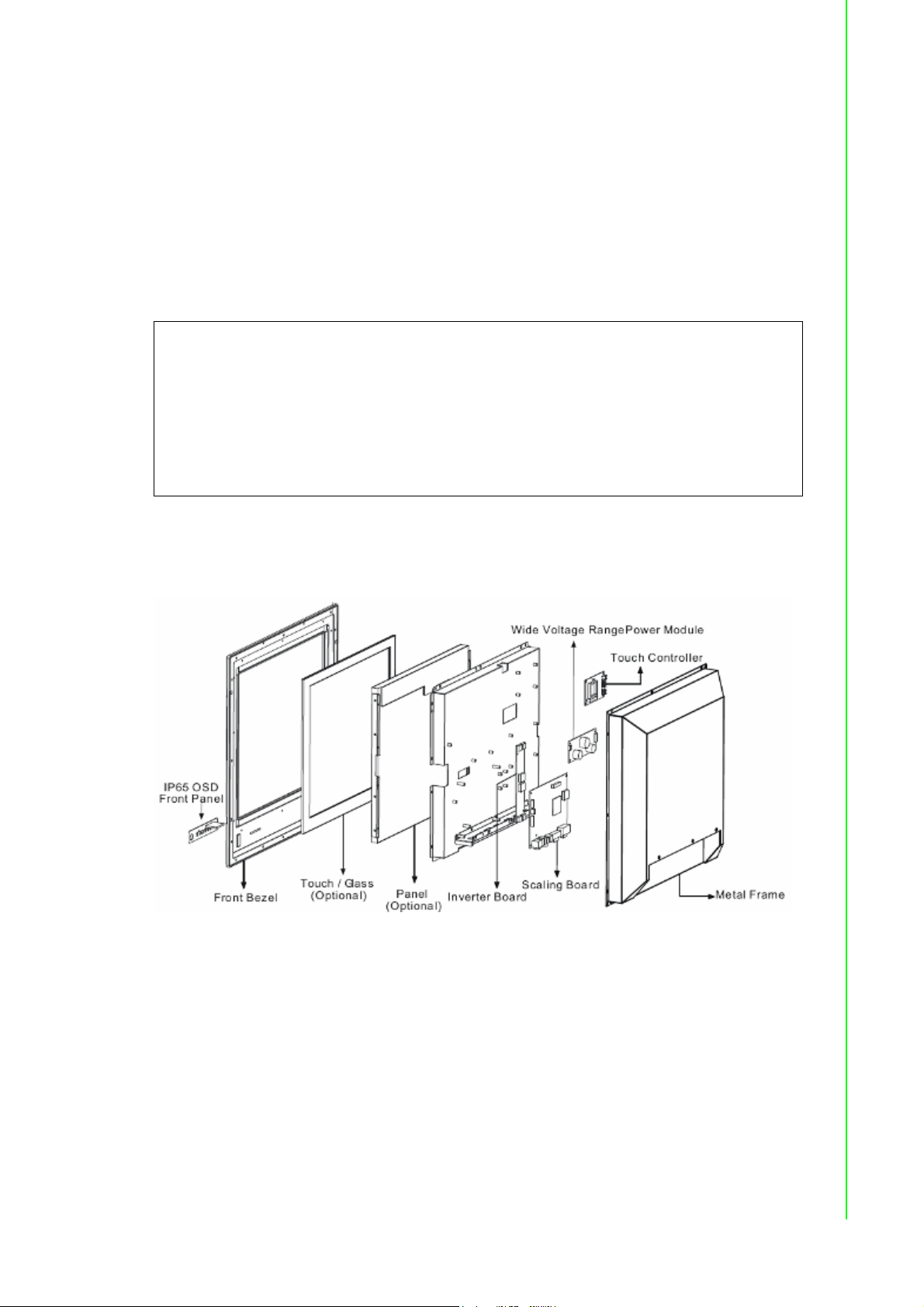
1.1.2 Basic Construction of Marine Bridge System Display
Figure 1.1 Basic Construction
3 FPM-8192V/8232V User Manual
Page 12
1.2 Touchscreen Solution (Optional)
1.2.1 Five-Wire Resistive Touchscreen (Optional 1)
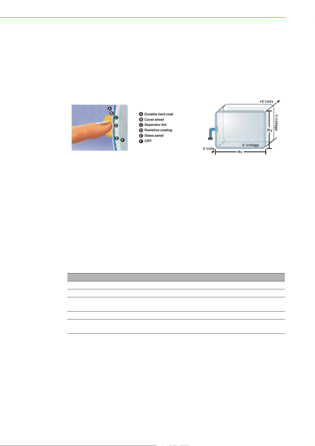
Introduction to Five-Wire Resistive Touchscreen
The five-wire resistive touchscreens use a glass panel with a uniform resistive coating. A thick polyester coversheet is tightly suspended over the top of the glass, separated by small, transparent insulating dots. The coversheet has a hard, durable
coating on the outer side and a conductive coating on the inner side.
When the screen is touched, the conductive coating makes electrical contact with the
coating on the glass. The voltages produced are the analog representation of the
position touched. The controller digitizes these voltages and transmits them to the
computer for processing. The five-wire technology utilizes the bottom substrate for
both X and Y-axis measurements. The flexible coversheet acts only as a voltagemeasuring probe. This means the touchscreen will continue working properly even
with non-uniformity in the cover sheet's conductive coating. The result is an accurate,
durable and reliable touchscreen that offers drift free operation. The touchscreens
are sealed against contamination and moisture. The coversheet is sealed to the
glass substrate with an industrial grade caulk. This prevents wicking of fluid between
the coversheet and glass. Also, the touchscreens are not air vented, thereby preventing fluid ingress through an air vent.
Brief Specifications
Subject Details
Input Method Finger, gloved hand, or stylus activation
Positional Accuracy Standard deviation error is less than 0.080 (2 mm)
Resolution Touchpoint density is based on controller resolution of 4096 x
4096
Touch Activation Force Typically less than 4 ounces (113 grams)
Light Transmission HL products: 80% +/–5% at 550 nm wavelength
Enhanced products: 60% +/–5% at 550 nm wavelength
FPM-8192V/8232V User Manual 4
Page 13

1.2.2 SecureTouch Surface Wave Touchscreen (Optional 2)
Introduction to SAW Touchscreen
The surface wave is the optical standard of touch. Its pure glass construction provides superior optical performance and makes it the most scratch-resistant technology available. It's nearly impossible to physically "wear out" this touchscreen.
The touch have a glass overlay with transmitting and receiving piezoelectric transducers for both the X and Y axes. The touchscreen controller sends a five-megahertz
electrical signal to the transmitting transducer, which converts the signal into ultrasonic waves within the glass. These waves are directed across the front surface of
the touchscreen by an array of reflectors. Reflectors on the opposite side gather and
direct the waves to the receiving transducer, which reconverts them into an electrical
signal—a digital map of the touchscreen surface.
Chapter 1 General Information
When you touch the screen, you absorb a portion of the wave traveling across it. The
received signal is then compared to the stored digital map, the change recognized,
and a coordinate calculated. This process happens independently for both the X and
Y axes. By measuring the amount of the signal that is absorbed, a Z-axis is also
determined. The digitized coordinates are transmitted to the computer for processing.
Brief Specifications
Subject Details
Input Method Finger or gloved hand (cloth, leather, or rubber) activation
Positional Accuracy Standard deviation of error is less than 0.080 in. (2 mm)
Resolution Touchpoint density is based on controller resolution of 4096 x
4096, plus 255 levels corresponding to touch pressure
Touch Activation Force Typically 2 to 3 ounces (55 to 85 grams)
Light Transmission Up to 90% per ASTM D1003-92
5 FPM-8192V/8232V User Manual
Page 14

FPM-8192V/8232V User Manual 6
Page 15

Chapter 2
2 Installation
Page 16

2.1 General Installation
The Marine Bridge System Display can be applied for several different installation
methods. Including panel (flush) mounting, bracket mounting, ceiling / wall mounting…etc. For panel (flush) mounting is normally for a ship’s wheelhouse use, it’s easy
to follow few steps to fix the display product in customer’s fixture.
Check the mechanical and mounting concept as below first. The fixture cut-out
dimension and mounting holes based on drawing.
1. Put the marine product on the fixture (console) from the front, and screw by four
M6 x 30 mm black bolts with nuts.
FPM-8192V/8232V User Manual 8
Page 17

Chapter 2 Installation
2. Use M4x 15mm bolts to drill through the fixture into the mounting holes on the
rear side of IP65 front bezel.(The quantity of mounting screws based on drawing)
3. Check the finished mounting concept.
9 FPM-8192V/8232V User Manual
Page 18

Note! VESA and wall mount with mounting kit by special request.
FPM-8192V/8232V User Manual 10
Page 19

2.2 Installation Notice
2.2.1 Brightness Control Knob Precaution
The dimming brightness control knob may be damaged by wrong placement. Please
make sure the right way to protect the knob.
2.2.2 Cable Connection Precaution
Make sure to use qualified shielded signal cable to connect to Marine products.
These cables including RGB, DVI, RS232, LAN, and USB cable should be connected
inside the area as marked below. For DC power connection, please make sure the
power cable is tightly connected by two screws of the terminal block.
Chapter 2 Installation
11 FPM-8192V/8232V User Manual
Page 20

FPM-8192V/8232V User Manual 12
Page 21

Chapter 3
3 Operating the LCD
Display
Page 22

3.1 OSD User Controls
The compact OSD in front control is a user-friendly interface both to remote the display function and dimming VR knob. The on screen display (OSD) contains several
functions that will let the user to adjust or set up the display to their preferred setting.
It also supplies special Hot Keys of clicking two keys together for easy flipping image
and auto adjusting color balance
Figure 3.1 OSD User Controls
The Dimming Knob
The TFT LCD display support hyper dimming function to adjust brightness from
nearly 0% to 100% via a easy to use VR knob.
Power On/ Off
Press the Power On/Off button to switch the TFT LCD display power.
Display Status LED indicator
When the TFT LCD display are normally operated, the LED indicator turns
to green light. And the LED turns to red light when the TFT LCD display
going to sleep.
Refer to the OSD Single Key Function as below and understand how to use the display functions step by step.
Single Key Function
FPM-8192V/8232V User Manual 14
Page 23

3.2 PIP (Picture in Picture) Function
When OSD Menu is disabled, it cycles through the available PIP display modes.
Repeated keystrokes will change the size of the PIP display to side-by-side (PAP)
display, and then back to normal display.
When OSD Menu is enabled, press“ ” returns to the previous menu level or
closes the OSD if pressed at the Menu level.
3.3 Auto Adjustment Function
When OSD Menu and PIP is disabled, press“ ” will perform the screen Auto
Adjustment.
When PIP is enabled, it switches the image in the Main Display to the PIP Display
and vice versa by pressing again. When image side-by-side (PAP mode) is active,
Chapter 3 Operating the LCD Display
the SWAP key ( ) exchanges the left and right displays.
3.4 Source Function
When OSD Menu is disabled, press “ ” will cycle through the available input
sources for the Main Display.
When OSD Menu is enabled, it moves right when navigating the Menu and Sub
Menu and increments a slider bar.
3.5 OSD Menu Function
After the power on, press” ” to enter OSD Menu.
15 FPM-8192V/8232V User Manual
Page 24

Figure 3.2 OSD Menu
There are 9 functions for in the OSD Menu for selection. For each function, it is very
easy to select by the other navigation keys to adjust. Following the direction as
below:
1. Press “ ” (Up) and “ ” (Down) to select each function.
2. Press “ ” to enter the sub menu, and press “ ” to exit.
3. Press “ ” (Up) and “ ” (Down) to select the sub-function.
4. When enter to each sub-function, press “ ” (Left) and “ ” (Right) to decrease
/ increase the bar value.
FPM-8192V/8232V User Manual 16
Page 25

3.6 Display Item Menu
Figure 3.3 Display Item Menu
Chapter 3 Operating the LCD Display
Display Item Menu
Menu Input Source Description and Usage
Brightness VGA
DVI
Contrast
Note! The Brightness control from OSD is removed for dimming knob tuning.
Composite SVideo
Adjust brightness only used in brightness knob. Adjustment is
no response here.
Press “ ” / “ ” to adjust contrast.
17 FPM-8192V/8232V User Manual
Page 26

3.7 Image Item Menu
Figure 3.4 Image Item Menu (VGA)
Figure 3.5 Image Item Menu (DVI)
FPM-8192V/8232V User Manual 18
Page 27

Figure 3.6 Image Item Menu (Composite, S-Video)
Chapter 3 Operating the LCD Display
Image Item Menu
Menu Input Source Description and Usage
Scaling** VGA
DVI
Composite SVideo
Flip Type
Auto-Adjust** VGA Only Initiate this to have the monitor logic to choose the
Phase Adjust Phase to optimize the display quality by
Clock Select Clock to adjust the horizontal screen size by
Hue Composite
and S-Video
Only
Saturation
Noise Reduction
Sharpness The Sharpness of the image may be optimized by
Change the scaling mode by using the“ ” / “ ”
buttons to select 1:1, Fill or aspect. Press “ “ to
activate the selected Scaling mode.
Using “ ” / “ ” and “ “ to select the display flip
for Normal, HFlip, VFlip, or HVFlip mode.
best settings for the current input signal.
using “ ” / “ ” to change the value.
using “ ” / “ ” to change the value.
Press “ ” / “ ” to select Hue to obtain the
desired color settings.
Press “ ” / “” to select Saturation to adjust
the optimal color degree level.
Using “ ” / “ ” and “ “ to select the Noise
Reduction for Off, Low, Mid, and High mode.
using “ ” / “ ” to change the value of the slider
bar.
19 FPM-8192V/8232V User Manual
Page 28

Note! For Scaling:
1. In 1:1 mode, the input image is centered on the screen. In Fill mode,
the input image is stretched / compressed to fill the available display
area.
2. In Aspect mode, the input image is stretched / compressed by the
same horizontal and vertical factor.
Note! For Auto-Adjust:
The only button available is “SELECT”. Note this may change the values
of Phase and Clock, and there is no ‘undo’ feature.
3.7.1 Position Item Menu
Figure 3.7 Position Item Menu (VGA)
Figure 3.8 Position Item Menu (DVI, Composite, S-Video)
FPM-8192V/8232V User Manual 20
Page 29

Position Item Menu
Menu Input Source Description and Usage
Zoom VGA
DVI
Composite SVideo
Zoom
Horizontal
Zoom
Vertica l
Vertica l VGA
Horizontal
Change the current Zoom setting only to the Main Display,
using “ ” / “ ” to select either In or Out. Zoom is at a temporary setting and will be lost at power down.
Zoom Horizontal is unavailable until the user performs a
Zoom In action. Using “ ” / “ ” to select either Left or
Right to change the current Horizontal Pan setting. Pan settings will be lost at power down.
Zoom Vertical is unavailable until the user performs a Zoom
In action. Using “ ” / “ ” to select either Up or Down to
change the current Vertical Pan setting and. Pan settings will
be lost at power down.
Move the screen up or down by using “ ” / “ ” to change
the vertical position value.
Move the screen left or right by using “ ” / “ ” to change
the horizontal position value.
Chapter 3 Operating the LCD Display
3.7.2 Color Item Menu
Figure 3.9 Color Item Menu (VGA)
21 FPM-8192V/8232V User Manual
Page 30

Figure 3.10 Color Item Menu (DVI, Composite, S-Video)
Color Item Menu
Menu Input Source Description and Usage
Temperature VGA
DVI
Composite SVideo
R
G
B
Internal Brightness
To configure color temperature, use “ ” / “ ” to
change the value to User Preset, 6500K, or 9300 K to set
a color temperature to suit your own preference. When
User Preset is selected, the values of the Red, Green,
and Blue sliders below are used to determine color settings.
Press “ ” / “ ” to adjust the Red color to obtain the
desired color settings.
Press “ ” / “ ” to adjust the Green color to obtain the
desired color settings.
Press “ ” / “ ” to adjust the Blue color to obtain the
desired color settings.
Press “ ” / “ ” to adjust the Red color to obtain the
desired color settings.
White Balance VGA Only When in “VGA” mode, press “Select” to adjust White Bal-
ance for the display setting.
FPM-8192V/8232V User Manual 22
Page 31

3.7.3 PIP Control Item Menu
Figure 3.11 PIP Control Item Menu
Chapter 3 Operating the LCD Display
PIP Control Item Menu
Menu Input Source Description and Usage
Mode VGA
DVI
Composite SVideo
Size PIP Size can be altered only when Single PIP mode is
Vertical** Both vertical and horizontal PIP position can be altered only
Horizontal
Use “ ” / “ ” to change the Mode value to be Off, Single,
or PAP **.
In Off mode, the Main display fills the entire screen.
In Single mode, a PIP display floats over the screen.
In PAP mode, the screen is divided into two side-by-side display areas.
selected. To configure the PIP display size, use “ ” / “ ” to
change the value to Small, Medium or Large.
when Single PIP mode is selected. Configure the PIP Vertical
and Horizontal Position, by using “ ” / “ ” to change the
value using the slider bar.
Note! For PAP mode:
When selecting “PAP” mode, the display area is now divided into two
parts. The left window displays the Main output, while the right window
displays the PIP output. Each window is half size of the total display
area. Each input is scaled down to fit the window.
Note! For PIP mode:
Note that the PIP screen can have any position on the screen. This can
be achieved by adjusting both Horizontal and Vertical positions.
23 FPM-8192V/8232V User Manual
Page 32

3.7.4 Main Display Item Menu
Figure 3.12 Main Display Item Menu
Press “ ” and “ ” to select the Main Display main source, including VGA, DVI,
Composite, and S-Video mode.
Press “ ” to choose “Select”.
3.7.5 PIP Display Item Menu
Figure 3.13 PIP Display Item Menu
FPM-8192V/8232V User Manual 24
Page 33

Press “ ” and “ ” to select the PIP Display main source, including VGA, DVI,
Composite, and S-Video mode.
Press “ ” to choose “Select”.
3.7.6 Audio Item Menu (Optional)
Chapter 3 Operating the LCD Display
Figure 3.14 Audio Item Menu
Audio Item Menu
Menu Input Source Description and Usage
Volume VGA
DVI
Composite S-
Balance
Treble
Bass
Mute To turn mute off/on, select either On/Off for Mute. By default,
Video
To adjust the volume, use “ ” / “ ” to change the value of
the slider bar to increase or decrease the volume.
To configure the audio balance, either left or right, use “ ” /
“ ” to change the value of the slider bar to change the value.
Increase or decrease the audio treble by using “ ” / “ ” to
change the value.
To configure the bass, use “ ” / “ ” to change the bass
value.
mute is set to No, or turned off.
25 FPM-8192V/8232V User Manual
Page 34

3.7.7 Reset Item Menu
Figure 3.15 Reset Item Menu
Factory Reset Item Menu
Menu Input Source Description and Usage
Factory
Reset
VGA
DVI
Composite SVideo
To reset all settings to factory defaults, open the Factory Reset
Item. Use “ ” / “ ” to select the “Yes” option, and press
“”.
WARNING: All user adjustments will be lost. Press “EXIT“
( )to return to the Main Menu without making changes.
FPM-8192V/8232V User Manual 26
Page 35

Appendix A
A Cleaning the Monitor
Page 36

A.1 Cleaning the Monitor
1. Make sure the monitor is turned off.
2. Never spray or pour any liquid directly on the screen or case.
3. Wipe the screen with a clean, soft, lint-free cloth. This removes dust and other particles.
4. The display area is highly prone to scratching. Do not use ketone type material (ex. Ace-
tone), Ethyl alcohol, toluene, ethyl acid or Methyl chloride to clear the panel. It may
permanently damage the panel and void the warranty.
5. If it is still not clean enough, apply a small amount of non-ammonia, non-alcohol based
glass cleaner onto a clean, soft, lint-free cloth, and wipe the screen.
6. Don’t use water or oil directly on the monitor. If droplets are allowed to drop on the
monitor permanent staining or discoloration may occur.
FPM-8192V/8232V User Manual 28
Page 37

Appendix B
B Troubleshooting
Page 38

B.1 Disclaimer
We do not recommend using any ammonia or alcohol-based cleaners on the monitor
screen or case. Some chemical cleaners have been reported to damage the screen
and/or case of the monitor. Seller will not be liable for damage resulting from the use
of any ammonia or alcohol-based cleaner.
B.2 Troubleshooting
If your monitor fails to operate correctly, consult the following chart for possible solution before calling for repairs:
Condition Check Point
The picture does not
appear
Check if the signal cable is firmly seated in the socket.
Check if the Power is ON at the computer
Check if the brightness control is at the appropriate position, not at
the minimum.
The screen is not
synchronized
The position of the
screen is not in the
center
The screen is too
bright (too dark).
The screen is shaking or waving
Check if the signal cable is firmly seated in the socket.
Check if the output level matches the input level of your computer.
Make sure the signal timings of the computer system are within the
specification of the monitor.
If your computer was working with a CRT monitor, you should check
the current signal timing and turn off your computer before you connect the VGA Cable to this monitor.
Adjust the H-position, and V-position, or Perform the Auto adjustment.
Check if the brightness or contrast control is at the appropriate position, not at the Maximum (Minimum).
Perform the Auto adjustment..
Moving all objects which emit a magnetic field such as motor or
transformer, away from the monitor.
Check if the specific voltage is applied.
Check if the signal timing of the computer system is within the specification of monitor.
If you are unable to correct the fault by using this chart, stop using your monitor and
contact your distributor or dealer for further assistance.
FPM-8192V/8232V User Manual 30
Page 39

Appendix C
C Supported Modes
Page 40

C.1 Graphics
No. Resolution Frequency (Hz) Note
1 640x350 70 IBM
2 640x400 70 IBM
3 640x480 60 VESA
4 640x480 72 VESA
5 640x480 75 VESA
6 720x400 70 IBM
7 800x600 56 VESA
8 800x600 60 VESA
9 800x600 72 VESA
10 800x600 75 VESA
11 1024x768 60 VESA
12 1024x768 70 VESA
13 1024x768 75 VESA
14 1280x768 60
15 1152x864 75
16 1280x960 60 VESA
17 1280x1024 60 VESA
18 1280x1024 60 HP
19 1280x1024 70 NCD
20 1280x1024 72 HP
21 1280x1024 75 VESA
22 1600x1200 60 VESA
23 1920x1200 60 VESA
24 1360x768 60
C.2 Video
No.
1 NTSC / 480I / 525I 720 x 240 x 60I
2 PAL / 576I /625I 720 x 288 x 50I
3 480P 720 x 480 x 60P
4 (HDTV) 720P 1280 x 720 x 50P
5 (HDTV) 720P 1280 x 720 x 60P
6 (HDTV) 1080I 1920 x 1080 x 50I
7 (HDTV) 1080P 1920 x 1080 x 60I
Not all modes will be supported, due to different panel brands
FPM-8192V/8232V User Manual 32
Page 41

Appendix D
D RS-232 Command
Code (Optional)
Page 42

D.1 RS-232 Command Code
01 DOWN 0x04, 0x12, 0x02, 0xE8, 0x00
02 UP 0x04, 0x12, 0x03, 0xE7, 0x00
03 LEFT 0x04, 0x12, 0x05, 0xE5, 0x00
04 RIGHT 0x04, 0x12, 0x06, 0xE4, 0x00
05 ENTER 0x04, 0x12, 0x07, 0xE3, 0x00
06 EXIT 0x04, 0x12, 0x08, 0xE2, 0x00
07 SWAP 0x04, 0x12, 0x0A, 0xE0, 0x00
08 SOURCE 0x04, 0x12, 0x0E, 0xDC, 0x00
09 POWER 0x04, 0x12, 0x0F, 0xDB, 0x00
10 AUTO ADJUST 0x04, 0x12, 0x11, 0xD9, 0x00
11 ASPECT 0x04, 0x12, 0x14, 0xD6, 0x00
12 MENU 0x04, 0x12, 0x15, 0xD5, 0x00
13 PIP 0x04, 0x12, 0x16, 0xD4, 0x00
14 VolDown 0x04, 0x12, 0x19, 0xD1, 0x00
15 VolUp 0x04, 0x12, 0x1A, 0xD0, 0x00
16 RESET 0x04, 0x12, 0x23, 0xC7, 0x00
17 AUTO COLOR 0x04, 0x12, 0x29, 0xC1, 0x00
18 FLIP 0x04, 0x12, 0x2C, 0xBE, 0x00
19 MUTE 0x04, 0x12, 0x2D, 0xBD, 0x00
20 ACK 0x03, 0x0C, 0xF1
Description: ex. DOWN 0x04, 0x12, 0x02, 0xE8,
Function par1, par2, par3, par4
Function: DOWNÎdown key
Par1: 0x04Îlength (cannot be modified by user)
Par2: 0x12Îinquiry code (cannot be modified by user)
Par3: 0x02Îcommand code (can be modified by user)
Par4: 0xE8Îcheck sum (cannot be modified by user)
FPM-8192V/8232V User Manual 34
Page 43

Appendix E
E Transflective Display
(Optional)
Page 44

E.1 Transflective Display
Transflective LCD technology can be applied to certain selected regular TFT LCD to
introduce the LCD with a reflective function. With the imposed reflective function, the
modified LCD can reflect the ambient light passing the LCD cell and utilize the
reflected light beams as its illumination. The stronger the ambient light is, the brighter
the LCD will appear. As a result, the modified LCD is viewable under lighting conditions including direct sunlight.
E.2 Features
1. Readable under all lighting conditions including direct sunlight.
2. Enhanced contrast ratio for both indoor and outdoor conditions.
3. Ultimate indoor color saturation, brightness, and viewing angle.
4. Full mechanical and electrical are compliant with the existent system.
5. Power saving and backlight life preserving in outdoor applications.
No extra heat generation even it is viewed at higher brightness.
The following table shows the outdoor readability for the Marine Bridge System Display models.
Outdoor Readability
Model Number
Ambient light(nit)
Brightness gain (nit)
Reflectance(net)(%)
R08T200MRT1TR
10,000 10,000 10,000 10,000 10,000 10,000
30,000 30,000 30,000 30,000 30,000 30,000
80,000 80,000 80,000 80,000 80,000 80,000
432.7 437.5 680 490 500 312.5
620 670 870 630 630 456
1,180 1,150 1,320 900 830 680
1.20% 1.20% 1% 0.83% 0.50% 0.70%
1.15% 1.15% 0.98% 0.70% 0.65% 0.68%
1.16% 1.10% 0.90% 0.45% 0.40% 0.45%
R10L100MRM2TR
R15T600MRA1TR
R17L500MRA2TR
R19L300MRA1TR
R20L100MRA2TR
FPM-8192V/8232V User Manual 36
Page 45

E.3 Transflective Brightness Testing
E.3.1 Dark Room Testing Instructions
1. Put the panel on table and plug the inverter, adjust the screen to white color
background.
2. Open the brightness testing equipment and make the zero value on the Equip-
ment.
3. Put the brightness detection sensor on the front of the LCD panel to measure
the value.
4. Make sure that brightness on the OSD is adjusted to the maximum value.
5. After each time measure the brightness lamp level change, it is necessary to
wait for 30 minutes at least to ensure the brightness in the labs room in homogeneous or consistent.
6. All testing are applied to naked LCD without any glass or sensor on the front
side.
Brightness Inspection:
The brightness inspection is based on Picture 2 to measure sample:
Appendix E Transflective Display (Optional)
Sample
Panel
Panel A 221 317 43.4 --- 20,000nit
Panel B 210 315 50 0.67(test
**Our Labs ambient light is just for 10,000 nits, 20,000nit, 30,000nit, 40,000 nit or
more ambient light value can be calculated by formula to estimate the brightness
level of LCD panel
Original
Brightness(nits)
Finished Brightness(nit)
Increase
Proportion (%)
Reflection
Rate (%)
nits:20,000 )
Ambient
Light
20,000 nit
37 FPM-8192V/8232V User Manual
Page 46

E.3.2 Environment: Outdoor Readability Measure
The following tables are our samples for outdoor readability measure.
8.4” R08T200-T1TR, 800x600@60Hz, 75Hz
Ambient light View degree 10,000 nit 30,000nit 80,000nit
Brightness gain(BL ON) 35° 437.5 nit 620 nit 1180 nit
Reflectance(net) 1.2% 1.15% 1.16%
10.4” R10L600-P1TR, 800x600@60Hz, 75Hz
Ambient light View degree 10,000 nit 30,000nit 80,000nit
Brightness gain(BL ON) 35° 437.5 nit 670 nit 1150 nit
Reflectance(net) 1.2% 1.15% 1.1%
15” R15T600-A1TR, 1024x768@60Hz, 75Hz
Ambient light View degree 10,000 nit 30,000nit 80,000nit
Brightness gain(BL ON) 35° 680 nit 870 nit 1100 nit
Reflectance(net) 1% 0.98% 0.8%
E.4 Caution on Handling Transflective LCD
E.4.1 Operation & Storage Temperature Caution
Although transflective LCD is mainly used in outdoor environment and can increase
the effective lights under sunlight, it is suggested that you should keep the LCD in
appropriate temperature for operation and storage. To ensure the transflective LCD
work stably, 0~50°C (32-121°F) operation and storage temperature is suitable.
Suggestion: Temperature 0~50°C (32-121°F) is appropriate for operation and storage on transflective LCD.
E.4.2 Contrast Ratio to Ambient Light Caution
Contrast ratio is a factor that can influence the readability. It is possible that we get
pretty high brightness measurement but the panel is not sunlight readable. For example, the LCD is in 80,000 nits outside ambient light level, even we have very high
brightness but the contrast to the ambient light is too low, we might not be able to see
the clear LCD screen image. In order to be sunlight readable, both brightness and
contrast ratio to the ambient light are needed to be in proper range.
Suggestion: It should make the proper contrast ratio to the ambient light condition to
ensure that LCD screen image is clear.
E.4.3 Protection Glass Selection
If you demand for built-in protection glass, it is needed to use the material whose
reflectance rate is less than 1%. It should be careful when using protection glass.
Generally, the reflectance rate of protection glass can be as high as 4~6%, but we
can provide the reflectance ration glass which is less 0.6%, so that the sunlight readability performance can work very well.
Suggestion: Select an appropriate glass if you need to built-in protection glass. In
addition, please feel free to inquire us for any protection glass information.
FPM-8192V/8232V User Manual 38
Page 47

Appendix E Transflective Display (Optional)
E.5 Touchscreen Selection
Due to using pure glass instead of the coating, ELO SAW and IR touch are ideal
selection for touch solution on transflective LCD, they have lower reflectance rate
than traditional resistive and capacitive touchscreen that have coating on them.
Since our technology is based on transflective principle, the glass or sensor will
reduce the sunlight reflect out. It would have problem to use high reflectance sensor
or glass on transflective LCD.
Suggestion: ELO SAW and IR touch are recommended for touch screen solution on
transflective LCD.
39 FPM-8192V/8232V User Manual
Page 48

www.advantech.com
Please verify specifications before quoting. This guide is intended for reference
purposes only.
All product specifications are subject to change without notice.
No part of this publication may be reproduced in any form or by any means,
electronic, photocopying, recording or otherwise, without prior written permission of the publisher.
All brand and product names are trademarks or registered trademarks of their
respective companies.
© Advantech Co., Ltd. 2007
 Loading...