

Advantech EKI-9516-C0IDW10E, EKI-9516P-LV, EKI-9512P-HV, EKI-9512-P0IDH10E, EKI-9512-P0IDL10E User Manual
...Page 1

User Manual
EKI-9500 Series
Full Managed Ethernet Switches
Page 2

Copyright
Part No. XXXXXXXXXX Edition 1
Printed in Taiwan September 2016
The documentation and the software included with this product are copyrighted 2016
by Advantech Co., Ltd. All rights are reserved. Advantech Co., Ltd. reserves the right
to make improvements in the products described in this manual at any time without
notice. No part of this manual may be reproduced, copied, translated or transmitted
in any form or by any means without the prior written permission of Advantech Co.,
Ltd. Information provided in this manual is intended to be accurat e and reliable. However, Advantech Co., Ltd. assumes no responsibility for its use, nor for any infringements of the rights of third parties, which may result from its use.
Acknowledgements
Intel and Pentium are trademarks of Intel Corporation.
Microsoft Windows and MS-DOS are registered trademarks of Microsoft Corp.
All other product names or trademarks are properties of their respective owners.
Product Warranty (5 years)
Advantech warrants to you, the original purchaser, that each of its products will be
free from defects in materials and workmanship for five years from the date of purchase.
This warranty does not apply to any products which have been repaired or altered by
persons other than repair personnel authorized by Advantech, or which have been
subject to misuse, abuse, accident or improper installation. Advantech assumes no
liability under the terms of this warranty as a consequence of such events.
Because of Advantech’s high quality-control standards and rigorous testing, most of
our customers never need to use our repair service. If an Advantech product is defective, it will be repaired or replaced at no charge during the warranty pe riod. For out ofwarranty repairs, you will be billed according to the cost of replacement materials,
service time and freight. Please consult your dealer for more details.
If you think you have a defective product, follow these steps:
1. Collect all the information about the problem encountered. (For example, CPU
speed, Advantech products used, other hardware and software used, etc.) Note
anything abnormal and list any on screen messages you get when the problem
occurs.
2. Call your dealer and describe the problem. Please have your manual, product,
and any helpful information readily available.
3. If your product is diagnosed as defective, obtain an RMA (return merchandize
authorization) number from your dealer. This allows us to process your return
more quickly.
4. Carefully pack the defective product, a fully-completed Repair and Replacement
Order Card and a photocopy proof of purchase date (such as your sales receipt)
in a shippable container. A product returned without proof of the purchase date
is not eligible for warranty service.
5. Write the RMA number visibly on the outside of the package and ship it prepaid
to your dealer.
EKI-9500 Series User Manual ii
Page 3

Declaration of Conformity
CE
This product has passed the CE test for environmental specifications when shielded
cables are used for external wiring. We recommend the use of shielded cables. This
kind of cable is available from Advantech. Please contact your local supplier for
ordering information.
This product has passed the CE test for environmental specifications. Test conditions
for passing included the equipment being operated within an industrial enclosure. In
order to protect the product from being damaged by ESD (Electrostatic Discharge)
and EMI leakage, we strongly recommend the use of CE-compliant industrial enclosure products.
FCC Class A
Note: This equipment has been tested and found to comply with the limit s for a Class
A digital device, pursuant to part 15 of the FCC Rules. These limits are designed to
provide reasonable protection against harmful interference when the equipment is
operated in a commercial environment. This equipment generates, uses, and can
radiate radio frequency energy and, if not installed and used in accordance with the
instruction manual, may cause harmful interference to radio communications. Operation of this equipment in a residential area is likely to cause harmful interference in
which case the user will be required to correct the interference at his own expense.
FCC Class B
Note: This equipment has been tested and found to comply with the limit s for a Class
B digital device, pursuant to part 15 of the FCC Rules. These limits are designed to
provide reasonable protection against harmful interference in a residential installation. This equipment generates, uses and can radiate radio frequency energy and, if
not installed and used in accordance with the instructions, may cause harmful interference to radio communications. However, there is no guarantee that interference
will not occur in a particular installation. If this equipment does cause harmful interference to radio or television reception, which can be determined by turning the equipment off and on, the user is encouraged to try to correct the interference by one or
more of the following measures:
Reorient or relocate the receiving antenna.
Increase the separation between the equipment and receiver.
Connect the equipment into an outlet on a circuit different from that to which the
receiver is connected.
Consult the dealer or an experienced radio/TV technician for help.
FM
This equipment has passed the FM certification. According to the National Fire Protection Association, work sites are classified into different classes, divisions and
groups, based on hazard considerations. This equipment is compliant with the specifications of Class I, Division 2, Groups A, B, C and D indoor hazards.
iii EKI-9500 Series User Manual
Page 4
Technical Support and Assistance
1. Visit the Advantech web site at www .advantech.com/support where you can find
the latest information about the product.
2. Contact your distributor, sales representative, or Advantech's customer service
center for technical support if you need additional assistance. Please have the
following information ready before you call:
– Product name and serial number
– Description of your peripheral attachments
– Description of your software (operating system, version, application software,
etc.)
– A complete description of the problem
– The exact wording of any error messages
Warnings, Cautions and Notes
Warning! Warnings indicate conditions, which if not observed, can cause personal
injury!
Caution! Cautions are included to help you avoid damaging hardware or losing
data. e.g.
There is a danger of a new battery exploding if it is incorrectly installed.
Do not attempt to recharge, force open, or heat the battery. Replace the
battery only with the same or equivalent type recommended by the manufacturer. Discard used batteries according to the manufacturer's
instructions.
Note! Notes provide optional additional information.
Document Feedback
To assist us in making improvements to this manual, we would welcome comments
and constructive criticism. Please send all such - in writing to: support@advantech.com
Packing List
Before setting up the system, check that the items listed below are included and in
good condition. If any item does not accord with the table, please contact your dealer
immediately.
1 x Full Managed Ethernet Switch
1 x Startup Manual
EKI-9500 Series User Manual iv
Page 5

Safety Instructions
1. Read these safety instructions carefully.
2. Keep this User Manual for later reference.
3. Disconnect this equipment from any AC outlet before cleaning. Use a damp
cloth. Do not use liquid or spray detergents for cleaning.
4. For plug-in equipment, the power outlet socket must be located near the equip-
ment and must be easily accessible.
5. Keep this equipment away from humidity.
6. Put this equipment on a reliable surface during installation. Dro pping it or letting
it fall may cause damage.
7. The openings on the enclosure are for air convection. Protect the equipment
from overheating. DO NOT COVER THE OPENINGS.
8. Make sure the voltage of the power source is correct before connecting the
equipment to the power outlet.
9. Position the power cord so that people cannot step on it. Do not place anything
over the power cord.
10. All cautions and warnings on the equipment should be noted.
11. If the equipment is not used for a long time, disconnect it from the power source
to avoid damage by transient overvoltage.
12. Never pour any liquid into an opening. This may cause fire or electrical shock.
13. Never open the equipment. For safety reasons, the equipment should be
opened only by qualified service personnel.
14. If one of the following situations arises, get the equipment checked by service
personnel:
15. The power cord or plug is damaged.
16. Liquid has penetrated into the equipment.
17. The equipment has been exposed to moisture.
18. The equipment does not work well, or you cannot get it to work according to the
user's manual.
19. The equipment has been dropped and damaged.
20. The equipment has obvious signs of breakage.
21. DO NOT LEAVE THIS EQUIPMENT IN AN ENVIRONMENT WHERE THE
STORAGE TEMPERA TURE MAY GO BELOW -20° C (-4° F) OR ABOVE 60° C
(140° F). THIS COULD DAMAGE THE EQUIPMENT. THE EQUIPMENT
SHOULD BE IN A CONTROLLED ENVIRONMENT.
22. CAUTION: DANGER OF EXPLOSION IF BATTERY IS INCORRECTLY
REPLACED. REPLACE ONLY WITH THE SAME OR EQUIVALENT TYPE
RECOMMENDED BY THE MANUFACTURER, DISCARD USED BATTERIES
ACCORDING TO THE MANUFACTURER'S INSTRUCTIONS.
23. The sound pressure level at the operator's position according to IEC 704-1:198 2
is no more than 70 dB (A).
DISCLAIMER: This set of instructions is given according to IEC 704-1. Advantech
disclaims all responsibility for the accuracy of any statements contained herein.
v EKI-9500 Series User Manual
Page 6

Wichtige Sicherheishinweise
1. Bitte lesen sie Sich diese Hinweise sorgfältig durch.
2. Heben Sie diese Anleitung für den späteren Gebrauch auf.
3. Vor jedem Reinigen ist das Gerät vom Stromnetz zu trennen. Verwenden Sie
Keine Flüssig-oder Aerosolreiniger. Am besten dient ein angefeuchtetes Tuch
zur Reinigung.
4. Die NetzanschluBsteckdose soll nahe dem Gerät angebracht und leicht zugän-
glich sein.
5. Das Gerät ist vor Feuchtigkeit zu schützen.
6. Bei der Aufstellung des Gerätes ist auf sicheren Stand zu achten. Ein Kippen
oder Fallen könnte Verletzungen hervorrufen.
7. Die Belüftungsöffnungen dienen zur Luftzirkulation die das Gerät vor überhit-
zung schützt. Sorgen Sie dafür, daB diese Öffnungen nicht abgedeckt werden.
8. Beachten Sie beim. AnschluB an das Stromnetz die AnschluBwerte.
9. Verlegen Sie die Netza nschluBleitung so , daB niemand darüber fallen kann. Es
sollte auch nichts auf der Leitung abgestellt werden.
10. Alle Hinweise und Warnungen die sich am Geräten befinden sind zu beachten.
11. Wird das Gerät über einen längeren Zeitraum nicht benutzt, sollten Sie es vom
Stromnetz trennen. Somit wird im Falle einer Übersp annung eine Beschädigung
vermieden.
12. Durch die Lüftungsöffnungen dürfen niemals Gegenstände oder Flü ssigkeiten in
das Gerät gelangen. Dies könnte einen Brand bzw. elektrischen Schlag auslösen.
13. Öffnen Sie niemals das Gerät. Das Gerät darf aus Gründen der elektrischen
Sicherheit nur von authorisiertem Servicepersonal geöffnet werden.
14. Wenn folgende Situationen auftreten ist das Gerät vom Stromnetz zu trennen
und von einer qualifizierten Servicestelle zu überprüfen:
15. Netzkabel oder Netzstecker sind beschädigt.
16. Flüssigkeit ist in das Gerät eingedrungen.
17. Das Gerät war Feuchtigkeit ausgesetzt.
18. Wenn das Gerät nicht der Bedienungsanleitung entsprechend funktioniert oder
Sie mit Hilfe dieser Anleitung keine Verbesserung erzielen.
19. Das Gerät ist gefallen und/oder das Gehäuse ist beschädigt.
20. Wenn das Gerät deutliche Anzeichen eines Defektes aufweist.
21. VOSICHT: Explisionsgefahr bei unsachgemaben Austausch der Batterie.Ersatz
nur durch densellben order einem vom Hersteller empfohlene-mahnlichen Typ.
Entsorgung gebrauchter Batterien navh Angaben des Herstellers.
22. ACHTUNG: Es besteht die Explosionsgefahr, falls die Batterie auf nicht fach-
männische Weise gewechselt wird. Verfangen Sie die Batterie nur gleicher oder
entsprechender Type, wie vom Hersteller empfohlen. Entsorgen Sie Batterien
nach Anweisung des Herstellers.
23. Der arbeitsplatzbezogene Schalldruckpegel nach DIN 45 635 Teil 1000 beträgt
70dB(A) oder weiger.
Haftungsausschluss: Die Bedienungsanleitungen wurden entsprechend der IEC704-1 erstellt. Advantech lehnt jegliche Verantwortung für die Richtigkeit der in diesem Zusammenhang getätigten Aussagen ab.
EKI-9500 Series User Manual vi
Page 7

Safety Precaution - Static Electricity
Follow these simple precautions to protect yourself from harm and the products from
damage.
To avoid electrical shock, always disconnect the power from your PC chassis
before you work on it. Don't touch any components on the CPU card or other
cards while the PC is on.
Disconnect power before making any configuration changes. The sudden rush
of power as you connect a jumper or install a card may damage sensitive electronic components.
vii EKI-9500 Series User Manual
Page 8
Technical Support and Assistance
1. Visit the Advantech web site at www .advantech.com/support where you can find
the latest information about the product.
2. Contract your distributor , sales represent ative, or Advantech's customer service
center for technical support if you need additional assistance. Please have the
following information ready before you call:
– Product name and serial number
– Description of your peripheral attachment
– Description of your sof tware (operating system, version, application sof tware,
etc.)
– A complete description of the problem
– The exact wording of any error messages
About This Manual
This user manual is intended to guide professional installers in installing and configuring the serial device server. It includes technical specifications, as well as procedures for the management of the devices.
EKI-9500 Series User Manual viii
Page 9

Contents
Chapter 1 Product Overview................................1
1.1 Supported Models.................................... ... .... ... ... ... ................................. 2
1.2 Specifications............................................................................................ 2
1.3 Hardware Views........................................................................................4
1.3.1 Front View . ...................................... .... ... ... ... ... .... ... ....................... 4
Figure 1.1 Front View ................................................................ 4
Figure 1.2 Front View ................................................................ 5
Figure 1.3 Front View ................................................................ 6
Figure 1.4 Front View ................................................................ 7
Figure 1.5 System LED Panel ...................................................8
Chapter 2 Switch Installation...............................9
2.1 Installation Guidelines.............................................................................10
2.1.1 Connecting Hardware.................. ... .... ... ... ... ............................... 10
2.2 Verifying Switch Operation...................................................................... 10
2.3 Installing the Switch ................................................................................ 10
2.3.1 Wall-Mounting.............................................................................10
Figure 2.1 Securing Wall Mounting Screws............................. 11
Figure 2.2 Switch Installation................................................... 11
2.4 Power Supply Installation........................................................................ 12
2.4.1 Overview.....................................................................................12
Figure 2.3 Power Wiring for EKI-9500 Series.......................... 12
2.4.2 Considerations............................................................................ 12
2.4.3 Grounding the Device..................... .... ... ... ... ... ............................ 13
Figure 2.4 Grounding Connection, Chassis Left Side View.....14
2.4.4 Wiring the Power Inputs.............................................................. 14
Figure 2.5 Removing the Protection Cap................................. 15
Figure 2.6 Installing the Power Cable...................................... 15
Figure 2.7 Standard M23 6-Pin Male DC Power Input
Connector............................................................... 15
2.5 Connecting the Ethernet Media............................................................... 16
2.5.1 Connecting the 10/100/1000BaseT(X)............................. ... ... ... .. 16
Figure 2.8 10/100/1000BaseT(X) Pin Assignment.......... ... ... .. 16
Figure 2.9 10/100BaseT(X) Pin Assignment ...........................16
2.6 Alarm Contact for Monitoring Internal Power ..........................................17
Figure 2.10 Alarm Contact Pin Assignment...............................17
2.7 Connecting the Console Terminal...................... ... ... ... .... ... ... ... .... ... ........17
Figure 2.11 M12 Console Pin Assignment ................................17
2.8 Connecting the USB Terminal................................................................. 18
Figure 2.12 M12 Console Pin Assignment ................................18
Chapter 3 Configuration Utility..........................19
3.1 First Time Setup...................................................................................... 20
3.1.1 Overview.....................................................................................20
3.1.2 Introduction................................................................................. 20
3.1.3 Administrative Interface Access.................................................. 20
3.1.4 Using the Graphical (Web) Interface......................... ... .... ... ... ... .. 21
3.1.5 Configuring the Switch for Network Access................................ 21
3.1.6 Configuring the Ethernet Ports........................ .... ... ... ... .... ...........22
3.2 Command Line Interface Configuration ..................................................22
3.2.1 Introduction to Command-Line Interface (CLI)....................... ... .. 22
ix EKI-9500 Series User Manual
Page 10

3.2.2 Accessing the CLI................................. .... ... ... ... .... ... ... ... ... .... ... .. 23
3.3 Web Browser Configuration.................................................................... 23
3.3.1 Preparing for Web Configuration................................................ 23
3.3.2 System Login.............................................................................. 23
Chapter 4 Managing Switch............................... 24
4.1 Log In...................................................................................................... 25
Figure 4.1 Login Screen..................................... ... ... ... ... .... ... .. 25
4.2 Recommended Practices........................................................................ 25
4.2.1 Changing Default Password....................................................... 25
Figure 4.2 System > Users > Accounts.......... .... ... ... ... ... .... ... .. 25
Figure 4.3 Changing a Default Password................................ 26
4.3 System.................................................................................................... 26
4.3.1 AAA............................................................................................. 26
Figure 4.4 System > AAA > Authentication List....................... 26
Figure 4.5 System > AAA > Authentication List > Add............ 28
Figure 4.6 System > AAA > Authentication Selection .............28
Figure 4.7 System > AAA > Accounting List............................ 29
Figure 4.8 System > AAA > Accounting List > Add................. 30
Figure 4.9 System > AAA > Accounting Selection ......... .... ... .. 31
4.3.2 Advanced Configuration ............................................................. 32
Figure 4.10 System > Advanced Configuratio n > DHCP
Server > Global ...................................................... 32
Figure 4.11 System > Advanced Configuratio n > DHCP
Server > Excluded Addresses................................ 32
Figure 4.12 System > Advanced Configuratio n > DHCP
Server > Excluded Addresses > Add ..................... 33
Figure 4.13 System > Advanced Configuratio n > DHCP
Server > Pool Summary......................................... 33
Figure 4.14 System > Advanced Configuratio n > DHCP
Server > Pool Summary > Add............................... 34
Figure 4.15 System > Advanced Configuratio n > DHCP
Server > Pool Configuration................................... 36
Figure 4.16 System > Advanced Configuratio n > DHCP
Server > Pool Options............................................ 38
Figure 4.17 System > Advanced Configuratio n > DHCP
Server > Pool Options > Add Vendor Option ......... 39
Figure 4.18 System > Advanced Configuratio n > DHCP
Server > Pool Options > Configure Vendor
Option..................................................................... 39
Figure 4.19 System > Advanced Configuratio n > DHCP
Server > Bindings................................................... 40
Figure 4.20 System > Advanced Configuratio n > DHCP
Server > Statistics .................................................. 40
Figure 4.21 System > Advanced Configuratio n > DHCP
Server > Conflicts................................................... 42
Figure 4.22 System > Advanced Configuration > DNS >
Configuration.......................................................... 42
Figure 4.23 System > Advanced Configuration > DNS >
IP Mapping.................... ... .... ... ... ... .... ... ... ... ... .... ... .. 43
Figure 4.24 System > Advanced Configuration > DNS >
IP Mapping > Add............. .... ... ... ... .... ... ... ... ... .... ... .. 44
Figure 4.25 System > Advanced Configuration > DNS >
Source Interface Configuration............................... 45
Figure 4.26 System > Advanced Configuratio n > Email
Alerts > Global........................................................ 45
Figure 4.27 System > Advanced Configuratio n > Email
Alerts > Test........................................................... 46
EKI-9500 Series User Manual x
Page 11

Figure 4.28 System > Advanced Configuration > Email
Alerts > Server............ .... ... ... .................................. 46
Figure 4.29 System > Advanced Configuration > Email
Alerts > Server > Add............................................. 47
Figure 4.30 System > Advanced Configuration > Email
Alerts > Statistics............ ... ... ... ... ............................ 47
Figure 4.31 System > Advanced Configuration > Email
Alerts > Subject....... ... ....................................... ... .. 48
Figure 4.32 System > Advanced Configuration > Email
Alerts > Address.......................................... ... ... ... .. 48
Figure 4.33 System > Advanced Configuration > Email
Alerts > Address > Add...................................... ... .. 49
Figure 4.34 System > Advanced Configuration > ISDP >
Global.....................................................................49
Figure 4.35 System > Advanced Configuration > ISDP >
Cache Table...........................................................50
Figure 4.36 System > Advanced Configuration > ISDP >
Interface.................................................................. 51
Figure 4.37 System > Advanced Configuration > ISDP >
Statistics.................................................................51
Figure 4.38 System > Advanced Configuration > Link
Dependency > Group .............................................52
Figure 4.39 System > Advanced Configuration > Link
Dependency > Group > Add...................................53
Figure 4.40 System > Advanced Configuration > Protection >
Denial of Service .................................................... 54
Figure 4.41 System > Advanced Configuration > sFlow >
Agent......................................................................55
Figure 4.42 System > Advanced Configuration > sFlow >
Receiver .................................................................56
Figure 4.43 System > Advanced Configuration > sFlow >
Poller ......................................................................56
Figure 4.44 System > Advanced Configuration > sFlow >
Poller > Add....................... ... ... ... .... ... ... ... .... ...........57
Figure 4.45 System > Advanced Configuration > sFlow >
Sampler..................................................................58
Figure 4.46 System > Advanced Configuration > sFlow >
Sampler > Add........................................................58
Figure 4.47 System > Advanced Configuration > sFlow >
Source Interface Configuration............................... 59
Figure 4.48 System > Advanced Configuration > SNMP >
Community .............................................................59
Figure 4.49 System > Advanced Configuration > SNMP >
Community > Add Community................................ 60
Figure 4.50 System > Advanced Configuration > SNMP >
Community > Add Community Group..................... 61
Figure 4.51 System > Advanced Configuration > SNMP >
Trap Receiver v1/v2 ............................................... 61
Figure 4.52 System > Advanced Configuration > SNMP >
Trap Receiver v1/v2 > Add..................................... 62
Figure 4.53 System > Advanced Configuration > SNMP >
Trap Receiver v3....................................................63
Figure 4.54 System > Advanced Configuration > SNMP >
Trap Receiver v3 > Add..........................................64
Figure 4.55 System > Advanced Configuration > SNMP >
Supported MIBs.............................. ... ... ... .... ... ... ... .. 65
Figure 4.56 System > Advanced Configuration > SNMP >
Access Control Group ............................................ 66
Figure 4.57 System > Advanced Configuration > SNMP >
Access Control Group > Add.................................. 67
xi EKI-9500 Series User Manual
Page 12

Figure 4.58 System > Advanced Configuration > SNMP >
User Security Model............................................... 68
Figure 4.59 System > Advanced Configuration > SNMP >
User Security Model > Add .................................... 69
Figure 4.60 System > Advanced Configuration > SNMP >
Source Interface Configuration............................... 70
Figure 4.61 System > Advanced Configuration > SNMP >
Server Configuration .............................................. 71
Figure 4.62 System > Advanced Configuration > SNTP >
Global Configuration.......................... ..................... 71
Figure 4.63 System > Advanced Configuration > SNTP >
Global Status.............................. ... .... ... ... ... ... .... ... .. 72
Figure 4.64 System > Advanced Configuration > SNTP >
Server Configuration .............................................. 73
Figure 4.65 System > Advanced Configuration > SNTP >
Server Configuration > Add.................................... 74
Figure 4.66 System > Advanced Configuration > SNTP >
Server Status.......................................................... 75
Figure 4.67 System > Advanced Configuration > SNTP >
Source Interface Configuration............................... 76
Figure 4.68 System > Advanced Configuratio n > Time
Ranges > Configuration ......................................... 76
Figure 4.69 System > Advanced Configuratio n > Time
Ranges > Configuration > Add............................... 77
Figure 4.70 System > Advanced Configuratio n > Time
Ranges > Entry Configuration................................ 78
Figure 4.71 System > Advanced Configuratio n > Time
Ranges > Entry Configuration > Add Absolute....... 78
Figure 4.72 System > Advanced Configuratio n > Time
Ranges > Entry Configuration > Add Periodic........ 79
Figure 4.73 System > Advanced Configuratio n > Time
Zone > Summary.................................................... 80
Figure 4.74 System > Advanced Configuratio n > Time
Zone > Time Zone.................................................. 82
Figure 4.75 System > Advanced Configuratio n > Time
Zone > Summer Time ............................................ 82
Figure 4.76 System > Advanced Configuration > Event
Manager > Alarm Status ........................................ 84
Figure 4.77 System > Advanced Configuration > Event
Manager > Trap Log............................................... 84
Figure 4.78 System > Advanced Configuration > Event
Manager > Policy List............................................. 85
Figure 4.79 System > Advanced Configuration > Event
Manager > Policy List > Add .................................. 86
Figure 4.80 System > Advanced Configuration > Event
Manager > Policy Selection.................................... 86
Figure 4.81 System > Advanced Configuration > Event
Manager > Severity Configuration.......................... 87
4.3.3 Basic Configuration...................................... ... ... .... ... .................. 88
Figure 4.82 System > Basic Configuration > Switch ................. 88
4.3.4 Configuration Storage................................................................. 88
Figure 4.83 System > Configuration Storage > Save................ 88
Figure 4.84 System > Configuration Storage > Reset............... 89
Figure 4.85 System > Configuration Storage > Erase Startup.. 89
Figure 4.86 System > Configuration Storage > Copy................ 90
4.3.5 Connectivity................................................................................ 90
Figure 4.87 System > Connectivity > IPv4 ................................ 90
Figure 4.88 System > Connectivity > IPv6 ................................ 92
Figure 4.89 System > Connectivity > IPv6 Neighbors............... 93
Figure 4.90 System > Connectivity > IPv6 Neighbors > Add ....94
EKI-9500 Series User Manual xii
Page 13

Figure 4.91 System > Connectivity > Service Port IPv4............94
Figure 4.92 System > Connectivity > Service Port IPv6............95
Figure 4.93 System > Connectivity > Service Port IPv6
Neighbors...............................................................96
Figure 4.94 System > Connectivity > Service Port IPv6
Neighbors List > Add..............................................97
Figure 4.95 System > Connectivity > DHCP Client Options...... 98
4.3.6 Firmware.....................................................................................98
Figure 4.96 System > Firmware > Status..................................98
Figure 4.97 System > Firmware > Configuration and Upgrade.99
4.3.7 Logs............................................................................................ 99
Figure 4.98 System > Logs > Buffered Log............................. 100
Figure 4.99 System > Logs > Event Log .................................101
Figure 4.100System > Logs > Persistent Log...........................101
Figure 4.101System > Logs > Hosts ........................................ 102
Figure 4.102System > Logs > Hosts > Add.............................. 103
Figure 4.103System > Logs > Configuration............................103
Figure 4.104System > Logs > Source Interface
Configuration........................................................ 104
Figure 4.105System > Logs > Statistics................................... 105
4.3.8 Management Access ................................................................106
Figure 4.106System > Management Access > System............ 106
Figure 4.107System > Management Access > Telnet.............. 107
Figure 4.108System > Management Access > Serial............... 107
Figure 4.109System > Management Access > CLI Banner...... 108
Figure 4.110System > Management Access > HTTP ..............109
Figure 4.111System > Management Access > HTTPS............109
Figure 4.112System > Management Access > SSH ................111
4.3.9 Passwords ................................................................................ 112
Figure 4.113System > Passwords > Line Password ................112
Figure 4.114System > Passwords > Enable Password............ 112
Figure 4.115System > Passwords > Password Rules.............. 113
Figure 4.116System > Passwords > Last Password ................114
Figure 4.117System > Passwords > Reset Passwords............ 115
4.3.10 PoE ...........................................................................................115
Figure 4.118System > PoE > PoE Configuration and Status ...115
Figure 4.119System > PoE > PoE Port Configuration and
Status ................................................................... 116
Figure 4.120System > PoE > PoE Port Statistics..................... 117
4.3.11 Port ...........................................................................................118
Figure 4.121System > Port > Summary ...................................118
Figure 4.122System > Port > Description.................................119
Figure 4.123System > Port > Cable Test ................................. 120
Figure 4.124System > Port > Mirroring.....................................121
Figure 4.125System > Port > Transceiver Brief.................. ... ... 122
4.3.12 Statistics.................................................................................... 123
Figure 4.126System > Statistics > System > Switch ................123
Figure 4.127System > Statistics > System > Port Summary....124
Figure 4.128System > Statistics > System > Port Detailed...... 125
Figure 4.129System > Statistics > System > Network DHC
Pv6 .......................................................................126
Figure 4.130System > Statistics > Time Based > Group..........127
Figure 4.131System > Statistics > Time Based > Group >
Add.......................................................................128
Figure 4.132System > Statistics > Time Based > Flow
Based ...................................................................130
Figure 4.133System > Statistics > Time Based > Flow
Based > Add.........................................................131
Figure 4.134System > Statistics > Time Based > Statistics ..... 132
4.3.13 Status........................................................................................ 132
xiii EKI-9500 Series User Manual
Page 14

Figure 4.135System > Status > ARP Cache ............................ 132
Figure 4.136System > Status > Resourc e Status .................... 133
Figure 4.137System > Status > Resource Configuration .........134
4.3.14 Summary .................................................................................. 134
Figure 4.138System > Summary > Dashboard........................ 134
Figure 4.139System > Summary > Description........................ 136
Figure 4.140System > Summary > Inventory........................... 136
Figure 4.141System > Summary > MAC Address Table.......... 137
4.3.15 Users ........................................................................................ 138
Figure 4.142System > Users > Accounts.................... ... ... .... ... 138
Figure 4.143System > Users > Accounts > Add ...................... 139
Figure 4.144System > Users > Auth Server Users .................. 140
Figure 4.145System > Users > Auth Server Users > Add........ 140
Figure 4.146System > Users > Sessions ................................. 141
4.3.16 Utilities...................................................................................... 141
Figure 4.147System > Utilities > System Reset ....................... 141
Figure 4.148System > Utilities > Ping ...................................... 142
Figure 4.149System > Utilities > Ping IPv6.............................. 143
Figure 4.150System > Utilities > TraceRoute........................... 144
Figure 4.151System > Utilities > TraceRoute IPv6................... 146
Figure 4.152System > Utilities > IP Address Conflict............... 147
Figure 4.153System > Utilities > Transfer................................ 148
4.4 Switching............................................................................................... 151
4.4.1 Class of Service........................................................................ 151
Figure 4.154Switching > Class of Service > 802.1p....... ... .... ... 152
4.4.2 DHCP Snooping ....................................................................... 152
Figure 4.155Switching > DHCP Snooping > Base > Global..... 152
Figure 4.156Switching > DHCP Snooping > Base > VLAN
Configuration........................................................ 153
Figure 4.157Switching > DHCP Snooping > Base > VLAN
Configuration > Add ............................................. 153
Figure 4.158Switching > DHCP Snooping > Base > Interface
Configuration........................................................ 154
Figure 4.159Switching > DHCP Snooping > Base > Static
Bindings................................................................ 155
Figure 4.160Switching > DHCP Snooping > Base > Static
Bindings > Add..................................................... 155
Figure 4.161Switching > DHCP Snooping > Base > Dynamic
Bindings................................................................ 156
Figure 4.162Switching > DHCP Snooping > Base >
Persistent ............................................................. 157
Figure 4.163Switching > DHCP Snooping > Base >
Statistics............................................................... 157
Figure 4.164Switching > DHCP Snooping > L2 Relay >
Global................................................................... 158
Figure 4.165Switching > DHCP Snooping > L2 Relay >
Interface Configuration......................................... 158
Figure 4.166Switching > DHCP Snooping > L2 Relay > VLAN
Configuration........................................................ 159
Figure 4.167Switching > DHCP Snooping > L2 Relay > VLAN
Configuration > Add ............................................. 160
Figure 4.168Switching > DHCP Snooping > L2 Relay >
Statistics............................................................... 161
4.4.3 IPv6 DHCP Snooping........................ ... .... ... ... ... ....................... 161
Figure 4.169Switching > IPv6 DHCP Snooping > Base >
Global................................................................... 161
Figure 4.170Switching > IPv6 DHCP Snooping > Base >
VLAN Configuration.............................................. 162
Figure 4.171Switching > IPv6 DHCP Snooping > Base >
VLAN Configuration > Add................................... 163
EKI-9500 Series User Manual xiv
Page 15

Figure 4.172Switching > IPv6 DHCP Snooping > Base >
Interface Configuration......................................... 163
Figure 4.173Switching > IPv6 DHCP Snooping > Base >
Static Bindings...................................... ................164
Figure 4.174Switching > IPv6 DHCP Snooping > Base >
Static Bindings > Add........ ... ... ... .... ... ... ... .... ... ... ... 165
Figure 4.175Switching > IPv6 DHCP Snooping > Base >
Dynamic Bindings.................................................166
Figure 4.176Switching > IPv6 DHCP Snooping > Base >
Persistent.............................................................. 166
Figure 4.177Switching > IPv6 DHCP Snooping > Base >
Statistics...............................................................167
4.4.4 DVLAN......................................................................................167
Figure 4.178Switching > DVLAN > Configuration.....................168
Figure 4.179Switching > DVLAN > Summary...........................168
Figure 4.180Switching > DVLAN > Interface Summary............ 169
4.4.5 Dynamic ARP Inspection..........................................................170
Figure 4.181Switching > Dynamic ARP Inspection > Global.... 170
Figure 4.182Switching > Dynamic ARP Inspection > VLAN..... 171
Figure 4.183Switching > Dynamic ARP Inspection > VLAN >
Add.......................................................................171
Figure 4.184Switching > Dynamic ARP Inspection >
Interface................................................................ 172
Figure 4.185Switching > Dynamic ARP Inspection > ACL .......173
Figure 4.186Switching > Dynamic ARP Inspection > ACL >
Add ACL...............................................................173
Figure 4.187Switching > Dynamic ARP Inspection > ACL >
Add Rule............................................................... 174
Figure 4.188Switching > Dynamic ARP Inspection >
Statistics...............................................................174
4.4.6 Filters........................................................................................ 175
Figure 4.189Switching > Filters > MAC Filters .........................176
Figure 4.190Switching > Filters > MAC Filters > Add...............177
4.4.7 GARP........................................................................................ 177
Figure 4.191Switching > GARP > Switch ................................. 178
Figure 4.192Switching > GARP > Port..................................... 178
4.4.8 IGMP Snooping............................ ... ....................................... ... 179
Figure 4.193Switching > IGMP Snooping > Configuration ....... 180
Figure 4.194Switching > IGMP Snooping > Interface
Configuration........................................................ 180
Figure 4.195Switching > IGMP Snooping > VLAN Status........181
Figure 4.196Switching > IGMP Snooping > VLAN Status >
Add.......................................................................182
Figure 4.197Switching > IGMP Snooping > Multicast Router
Configuration........................................................ 183
Figure 4.198Switching > IGMP Snooping > Multicast Router
VLAN Status......................................................... 184
Figure 4.199Switching > IGMP Snooping > Multicast Router
VLAN Configuration..............................................184
4.4.9 IGMP Snooping Querier............................... ... .... ... ................... 185
Figure 4.200Switching > IGMP Snooping Querier >
Configuration........................................................ 185
Figure 4.201Switching > IGMP Snooping Querier > VLAN
Configuration........................................................ 186
Figure 4.202Switching > IGMP Snooping Querier > VLAN
Configuration > Add.............. ... ... .... ... ... ... .... ... ... ... 186
Figure 4.203Switching > IGMP Snooping Querier > VLAN
Status ................................................................... 187
4.4.10 MLD Snooping.......... ... ... ....................................... ... ... .... ... ... ... 188
Figure 4.204Switching > MLD Snooping > Configuration......... 188
xv EKI-9500 Series User Manual
Page 16

Figure 4.205Switching > MLD Snooping > Interface
Configuration........................................................ 189
Figure 4.206Switching > MLD Snooping > Source Specific
Multicast............................................................... 190
Figure 4.207Switching > MLD Snooping > VLAN Status ......... 190
Figure 4.208Switching > MLD Snooping > VLAN Status >
Add....................................................................... 191
Figure 4.209Switching > MLD Snooping > Multicast Router
Configuration........................................................ 192
Figure 4.210Switching > MLD Snooping > Multicast Router
VLAN Status......................................................... 193
Figure 4.211Switching > MLD Snooping > Multicast Router
VLAN Status > Add .............................................. 193
4.4.11 MLD Snooping Querier............................................................. 194
Figure 4.212Switching > MLD Snooping Querier >
Configuration........................................................ 194
Figure 4.213Switching > MLD Snooping Querier > VLAN
Configuration........................................................ 195
Figure 4.214Switching > MLD Snooping Querier > VLAN
Configuration > Add ............................................. 195
Figure 4.215Switching > MLD Snooping Querier > VLAN
Status................................................................... 196
4.4.12 Multicast Forwarding Database................................................ 197
Figure 4.216Switching > Multicast Forwarding Database >
Summary.............................................................. 197
Figure 4.217Switching > Multicast Forwarding Database >
GMRP................................................................... 198
Figure 4.218Switching > Multicast Forwarding Database >
IGMP Snooping.................................................... 199
Figure 4.219Switching > Multicast Forwarding Database >
MLD Snooping...................................................... 200
Figure 4.220Switching > Multicast Forwarding Database >
Statistics............................................................... 200
4.4.13 MVR.......................................................................................... 200
Figure 4.221Switching > MVR > Global ................................... 201
Figure 4.222Switching > MVR > Group.................................... 202
Figure 4.223Switching > MVR > Group > Add .........................202
Figure 4.224Switching > MVR > Interface................................ 203
Figure 4.225Switching > MVR > Statistics ............................... 204
4.4.14 LLDP......................................................................................... 204
Figure 4.226Switching > LLDP > Global .................................. 204
Figure 4.227Switching > LLDP > Interface............ ... ... ... ... ....... 205
Figure 4.228Switching > LLDP > Interface > Add .................... 206
Figure 4.229Switching > LLDP > Local Devices ...................... 207
Figure 4.230Switching > LLDP > Remote Devices .................. 208
Figure 4.231Switching > LLDP > Statistics .............................. 208
4.4.15 LLDP-MED................................................................................ 209
Figure 4.232Switching > LLDP-MED > Global......................... 209
Figure 4.233Switching > LLDP-MED > Interface...................... 210
Figure 4.234Switching > LLDP-MED > Interface > Add........... 211
Figure 4.235Switching > LLDP-MED > Local Devices............. 211
Figure 4.236Switching > LLDP-MED > Remote Devices......... 212
4.4.16 Port Channel............................................................................. 212
Figure 4.237Switching > Port Channel > Summary ................. 213
Figure 4.238Switching > Port Channel > Statistics .................. 214
4.4.17 Port Security............................................................................. 215
Figure 4.239Switching > Port Security > Global.......... ... ... .... ... 215
Figure 4.240Switching > Port Security > Interface ................... 216
Figure 4.241Switching > Port Security > Static MAC ...............217
Figure 4.242Switching > Port Security > Static MAC > Add..... 218
EKI-9500 Series User Manual xvi
Page 17

Figure 4.243Switching > Port Security > Dynamic MAC ..........219
4.4.18 Protected Ports......................................................................... 219
Figure 4.244Switching > Protected Ports > Configuration........219
Figure 4.245Switching > Protected Ports > Configuration >
Add.......................................................................220
4.4.19 Spanning Tree .................................................... ... ... ... .... ... ... ... 220
Figure 4.246Switching > Spanning Tree > Switch.................... 221
Figure 4.247Switching > Spanning Tree > MST....................... 222
Figure 4.248Switching > Spanning Tree > MST Port............... 223
Figure 4.249Switching > Spanning Tree > CST.......................224
Figure 4.250Switching > Spanning Tree > CST Port................ 225
Figure 4.251Switching > Spanning Tree > Statistics................227
4.4.20 VLAN.........................................................................................227
Figure 4.252Switching > VLAN > Status .................................. 228
Figure 4.253Switching > VLAN > Status > Add........................229
Figure 4.254Switching > VLAN > Port Configuration................ 229
Figure 4.255Switching > VLAN > Port Summary...................... 230
Figure 4.256Switching > VLAN > Switchport Summary ...........232
Figure 4.257Switching > VLAN > Internal Usage.....................233
Figure 4.258Switching > VLAN > Reset................................... 233
Figure 4.259Switching > VLAN > Status .................................. 234
4.4.21 IP Subnet Based VLAN............................................................. 234
Figure 4.260Switching > IP Subnet Based VLAN > Status ......234
Figure 4.261Switching > IP Subnet Based VLAN > Status >
Add.......................................................................235
4.4.22 MAC Based VLAN .................................................................... 235
Figure 4.262Switching > MAC Based VLAN > Status ..............235
Figure 4.263Switching > MAC Based VLAN > Status > Add....236
4.4.23 Protocol Based VLAN ............................................................... 236
Figure 4.264Switching > Protocol Based VLAN > Status.........236
Figure 4.265Switching > Protocol Based VLAN > Status >
Add.......................................................................237
Figure 4.266Switching > Protocol Based VLAN >
Configuration........................................................ 238
4.4.24 Private VLAN ............................................................................ 239
Figure 4.267Switching > Private VLAN > Configuration...........240
Figure 4.268Switching > Private VLAN > Configuration >
Add VLAN............................................................. 240
Figure 4.269Switching > Private VLAN > Association..............241
Figure 4.270Switching > Private VLAN > Interface ..................241
4.4.25 X-Ring Pro ................................................................................ 243
Figure 4.271Switching > X-Ring Pro > Configuration...............243
Figure 4.272Switching > X-Ring Pro > Configuration > Add ....243
Figure 4.273Switching > X-Ring Pro > Status..........................244
4.5 Routing..................................................................................................245
4.5.1 ARP Table................................................................................. 245
Figure 4.274Routing > ARP Table > Summary........................246
Figure 4.275Routing > ARP Table > Summary > Add..............247
Figure 4.276Routing > ARP Table > Configuration.................. 247
Figure 4.277Routing > ARP Table > Statistics.........................248
4.5.2 IP............................................................................................... 248
Figure 4.278Routing > IP > Configuration................................248
Figure 4.279Routing > IP > Interface Summary.......................250
Figure 4.280Routing > IP > Interface Configuration.................251
Figure 4.281Routing > IP > Statistics....................................... 253
4.5.3 Router....................................................................................... 255
Figure 4.282Routing > Router > Route Table...........................255
Figure 4.283Routing > Router > Configured Routes................ 256
Figure 4.284Routing > Router > Configured Routes > Add......257
Figure 4.285Routing > Router > Summary............................... 258
xvii EKI-9500 Series User Manual
Page 18

4.6 Security................................................................................................. 259
4.6.1 Port Access Control.................................................................. 259
Figure 4.286Security > Port Access Control > Configuration... 259
Figure 4.287Security > Port Access Control > Port Summary . 260
Figure 4.288Security > Port Access Control > Port
Configuration........................................................ 262
Figure 4.289Security > Port Access Control > Port Details...... 264
Figure 4.290Security > Port Access Control > Statistics.......... 266
Figure 4.291Security > Port Access Control > Client
Summary.............................................................. 267
Figure 4.292Security > Port Access Control > Privileges
Summary.............................................................. 267
Figure 4.293Security > Port Access Control > History Log
Summary.............................................................. 268
4.6.2 RADIUS.................................................................................... 268
Figure 4.294Security > RADIUS > Configuration ..................... 269
Figure 4.295Security > RADIUS > Named Server ................... 269
Figure 4.296Security > RADIUS > Named Server > Add......... 270
Figure 4.297Security > RADIUS > Statistics............................ 271
Figure 4.298Security > RADIUS > Accounting Server............. 272
Figure 4.299Security > RADIUS > Accounting Server > Add... 272
Figure 4.300Security > RADIUS > Accounting Statistics ......... 273
Figure 4.301Security > RADIUS > Clear Statistics................... 274
Figure 4.302Security > RADIUS > Source Interface
Configuration........................................................ 274
4.6.3 TACACS+................................................................................. 274
Figure 4.303Security > TACACS+ > Configuration ..... ... ... .... ... 275
Figure 4.304Security > TACACS+ > Server Summary ............ 275
Figure 4.305Security > TACACS+ > Server Summary > Add.. 276
Figure 4.306Security > TACACS+ > Server Configuration ...... 276
Figure 4.307Security > TACACS+ > Source Interface
Configuration........................................................ 277
4.7 QoS....................................................................................................... 277
4.7.1 Access Control Lists................................................................. 277
Figure 4.308QoS > Access Control Lists > Summary.............. 278
Figure 4.309QoS > Access Control Lists > Summary > Add ...279
Figure 4.310QoS > Access Control Lists > Configuration........ 280
Figure 4.311QoS > Access Control Lists > Configuration >
Add Rule........................... .... ... ... ... .... ... ................ 281
Figure 4.312QoS > Access Control Lists > Interfaces.............. 286
Figure 4.313QoS > Access Control Lists > Interfaces > Add... 287
Figure 4.314QoS > Access Control Lists > VLANs ..................288
Figure 4.315QoS > Access Control Lists > VLANs > Add........ 289
4.7.2 Class of Service........................................................................ 289
Figure 4.316QoS > Class of Service > IP DSCP...................... 290
Figure 4.317QoS > Class of Service > Interface...................... 290
Figure 4.318QoS > Class of Service > Queue......................... 291
Figure 4.319QoS > Class of Service > Drop Precedence........ 292
4.7.3 Diffserv...................................................................................... 293
Figure 4.320QoS > Diffserv > Global ....................................... 293
Figure 4.321QoS > Diffserv > Class Summary ........................ 294
Figure 4.322QoS > Diffserv > Class Summary > Add.............. 295
Figure 4.323QoS > Diffserv > Class Configuration .................. 295
Figure 4.324QoS > Diffserv > Class Configuration > Add
Match Criteria....................................................... 296
Figure 4.325QoS > Diffserv > Policy Summary........ ... ... ... .... ... 299
Figure 4.326QoS > Diffserv > Policy Summary > Add .............300
Figure 4.327QoS > Diffserv > Policy Configuration.................. 300
Figure 4.328QoS > Diffserv > Policy Configuration > Add
Class .................................................................... 301
EKI-9500 Series User Manual xviii
Page 19

Figure 4.329QoS > Diffserv > Policy Configuration > Add
Attribute................................................................301
Figure 4.330QoS > Diffserv > Service Summary......................304
Figure 4.331QoS > Diffserv > Service Summary > Add........... 305
Figure 4.332QoS > Diffserv > Service Statistics.......................305
Figure 4.333QoS > Diffserv > Policy Statistics......................... 306
xix EKI-9500 Series User Manual
Page 20

Chapter 1
1Product Overview
Page 21

1.1 Supported Models
Train switch EKI-9516P-HV EKI-9516-P0IDH10E 16GE PoE wide temp High volt-
EKI-9516P-L V EKI-9516-P0IDL10E 16GE PoE wide temp Low voltage
EKI-9516-WV EKI-9516-C0IDW10E 16GE w/o PoE wide temp Wide
EKI-9512P-HV EKI-9512-P0IDH10E 12GE PoE wide temp High volt-
EKI-9512P-L V EKI-9512-P0IDL10E 12GE PoE wide temp Low voltage
EKI-9512-WV EKI-9512-C0IDW10E 12GE w/o PoE wide temp Wide
Train switch EKI-9516DP-HV EKI-9 516-PFIDH10E 16FE PoE wide temp High voltage
EKI-9516DP-LV EKI-9516-PFIDL10E 16FE PoE wide temp Low voltage
EKI-9516D-WV EKI-9516-CFIDW10E 16FE w/o PoE wide temp Wide
EKI-9512DP-HV EKI-9512-PFIDH10E 12FE PoE wide temp High voltage
EKI-9512DP-LV EKI-9512-PFIDL10E 12FE PoE wide temp Low voltage
EKI-9512D-WV EKI-9512-CFIDW10E 12FE w/o PoE wide temp Wide
age input
input
voltage input
age input
input
voltage input
input
input
voltage input
input
input
voltage input
1.2 Specifications
Specifications Description
Interface I/O Port
Power Connector M23 connector
Physical Enclosure Aluminum extrusion
Protection Class IP67
Installation Wall mount
Dimensions
(W x H x D)
LED Display System LED SYS, Power 1, Power 2, CFG, ALM
Port LED DATA, PoE (only for EKI-9516P-LV, EKI-9516P-HV,
EKI-9516, EKI-9516P-HV and EKI-9516P-LV:
16 x 10/100/1000BaseT(X)
EKI-9516D, EKI-9516DP-HV and EKI-9516D
P-LV: 16 x 10/100/1000BaseT(X)
EKI-9512, EKI-9512P-HV and EKI-9512P-LV:
12 x 10/100/1000BaseT(X)
EKI-9512D, EKI-9512DP-HV and EKI-9512D
P-LV: 12 x 10/100/1000BaseT(X)
252 x 174 x 643mm (include M23 connector)
EKI-9512P-LV, EKI-9512P-HV, EKI-9516DP-LV,
EKI-9516DP-HV, EKI-9512DP-LV and EKI-9512DPHV)
EKI-9500 Series User Manual 2
Page 22

Specifications Description
Environment Operating
Temperature
Storage
Temperature
Ambient Relative
Humidity
Switch Properties MAC Address 16K-entry
Switching
Bandwidth
-40°C ~ 70°C (-40°F ~ 158°F)
-40°C ~ 85°C (-40°F ~ 185°F)
5 ~ 95% (non-condensing)
EKI-9516: 32 Gbps
EKI-9516D: 10.4 Gbps
EKI-9512: 24 Gbps
EKI-9512D: 9.6 Gbps
Power Power
Consumption
Power Input
~ 30 W (System)
EKI-9516: 24/48/72/96/110 Vdc
EKI-9516P-HV: 72/96/110 Vdc
EKI-9516P-LV: 24/48 Vdc
EKI-9512: 24/48/72/96/110 Vdc
EKI-9512P-HV: 72/96/110 Vdc
EKI-9512P-LV: 24/48 Vdc
Certifications Safety
EN50155
EN50121-3-2
EN45545
EMI
FCC Part 15 Subpart B Class A
CE EN55022 (CISPR)
EN55024 Class A
EMS
EN61000-6-2
EN61000-6-4
EN61000-4-2 (ESD) Level 3
EN61000-4-3 (RS) Level 3
EN61000-4-4 (EFT) Level 3
EN61000-4-5 (Surge) Level 3
EN61000-4-6 (CS) Level 3
Shock IEC 61373 Cat 1 Class B
Freefall IEC 60068-2-32
Vibration IEC 61373 Cat 1 Class B
3 EKI-9500 Series User Manual
Page 23
1.3 Hardware Views
1
3
4
67
9
8
2
5
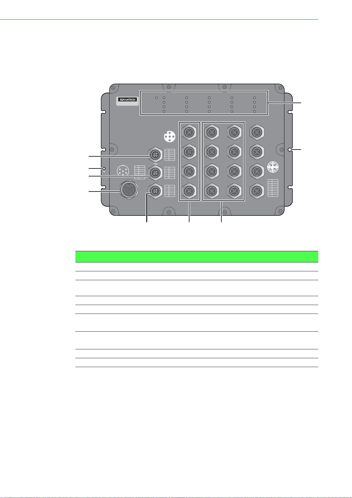
1.3.1 Front View
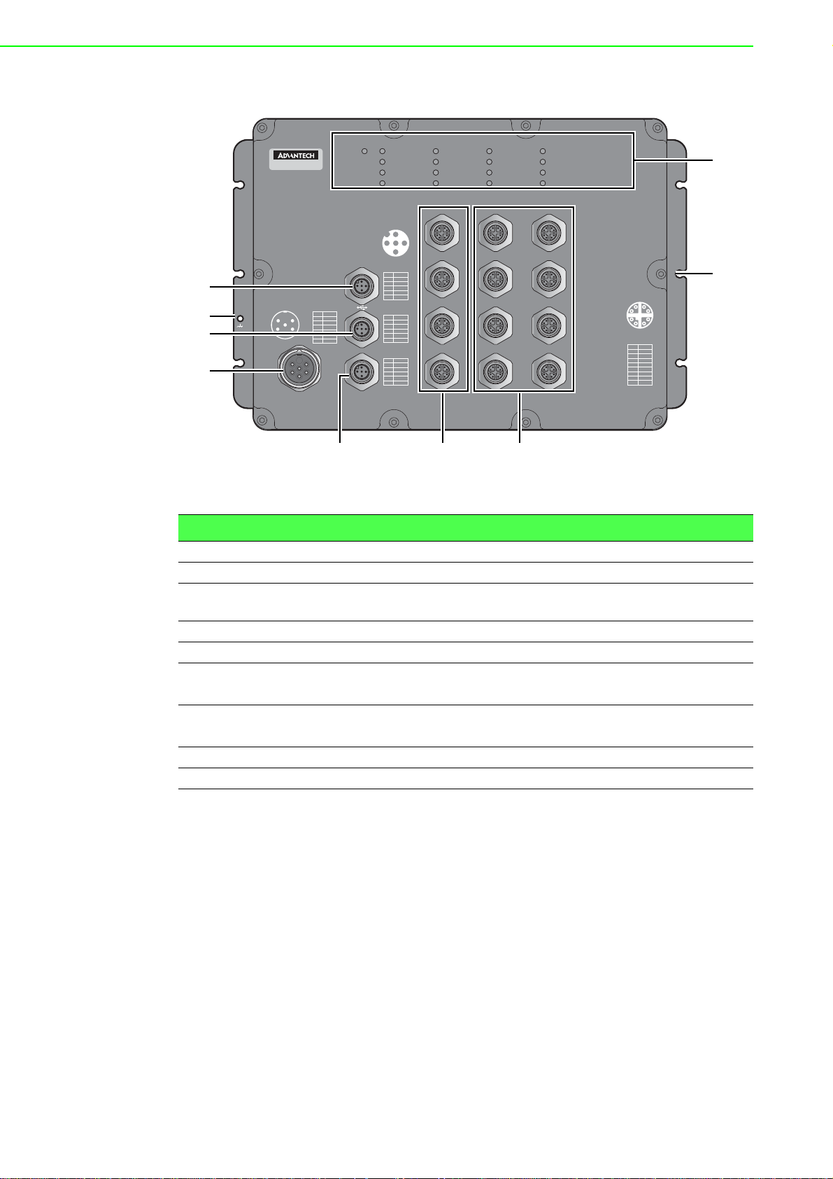
The following view applies to EKI-9516 and EKI-9516D.
DATADATADATA
1
2
3
4
5
4
6
3
7
2
1
8
Pair
Pin
+
1
DA
-
2
DA
+
DB
3
-
4
DB
+
DD
5
-
6
DD
-
7
DC
+
8
DC
EKI-9516
5
6
4
3
4
1
5
Power
PWR2
Pin PWR
+
L1
1
/
V
-
2
L1/V
2
3
GND
+
4
L2/
V
-
5
L
2/V
6
NA
3
1
6
2
3
Console
ALM
PWR1
SYS
CFG
ALM
153
Pin
1
2
3
4
5
Pin
1
2
3
4
5
Pin
1
2
3
4
5
DATA
13
14
15
16
2
4
Signal
DN
VBUS
NC
DP
GND
Signal
TX
RX
DSR
GND
DTR
Pair
P1-N
P1-P
P2-N
P2-P
NA
9
10
11
12
5
6
7
8
Figure 1.1 Front View
No. Item Description
1 USB port M12 5-pin (female) port for FW backup access.
2 Ground terminal Screw terminal used to ground chassis.
3 Console port M12 5-pin (female) port to access the managed switch's soft-
ware.
4 Power input port M23 connector 6-pin (male) DC power connector port.
5 Alarm port M12 5-pin (female) port to attach monitoring wires.
6ETH port
EKI-9516: 10/100/1000BaseT(X) x 4 (X-coding)
EKI-9516D: 10/100/1000BaseT(X) x 4 (D-coding)
7ETH port
EKI-9516: 10/100/1000BaseT(X) x 12 (X-coding)
EKI-9516D: 10/100/1000BaseT(X) x 12 (D-coding)
8 Mounting screw hole Screw holes (x6) used in the installation of a wall mounting plate
9 System LED panel See “System LED Panel” on page 8 for further details.
EKI-9500 Series User Manual 4
Page 24
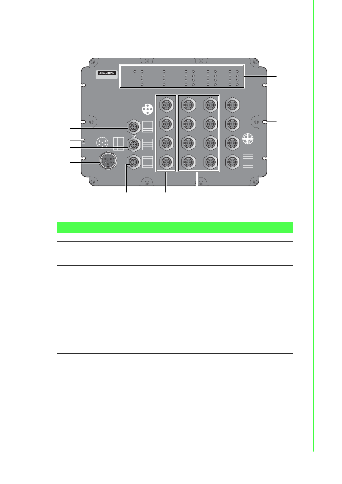
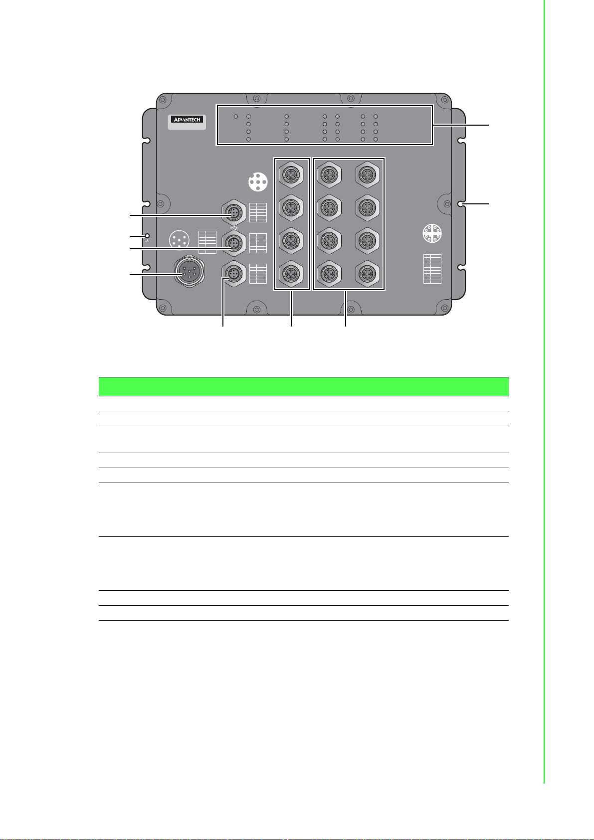
The following view applies to EKI-9516P-HV, EKI-9516P-LV, EKI-9516DP-HV and
1
3
4
67
9
8
2
5
EKI-9516DP-LV.
PoEDATAPoEDATAPoEDATA
1
2
3
4
5
4
6
3
7
2
1
8
Pair
Pin
+
1
DA
-
2
DA
+
DB
3
-
4
DB
+
DD
5
-
6
DD
-
7
DC
+
8
DC
EKI-9516P
1
5
6
4
3
5
4
Power
PWR2
Pin PWR
+
L1
1
/
V
-
2
L1/V
2
GND
3
+
4
L2/
V
-
5
L
2/V
6
NA
3
1
6
2
3
Console
ALM
PWR1
SYS
CFG
ALM
153
Pin
1
2
3
4
5
Pin
1
2
3
4
5
Pin
1
2
3
4
5
DATA
13
14
15
16
2
4
Signal
DN
VBUS
NC
DP
GND
Signal
TX
RX
DSR
GND
DTR
Pair
P1-N
P1-P
P2-N
P2-P
NA
9
10
11
12
5
6
7
8
Figure 1.2 Front View
No. Item Description
1 USB port M12 5-pin (female) port for FW backup access.
2 Ground terminal Scr ew terminal used to ground chassis.
3 Console port M12 5-pin (female) port to access the managed switch's soft-
ware.
4 Power input port M23 connector 6-pin (male) DC power connector port.
5 Alarm port M12 5-pin (female) port to attach monitoring wires.
6ETH port
EKI-9516P-HV and EKI-9516P-L V : 10/100/1000BaseT(X) x
4 (X-coding)
EKI-9516DP-HV and EKI-9516DP-LV: 10/100/
1000BaseT(X) x 4 (D-coding)
7ETH port
EKI-9516P-HV and EKI-9516P-L V : 10/100/1000BaseT(X) x
12 (X-coding)
EKI-9516DP-HV and EKI-9516DP-LV: 10/100/
1000BaseT(X) x 12 (D-coding)
8 Mounting screw hole Screw holes (x6) used in the installation of a wall mounting plate
9 System LED panel See “System LED Panel” on page 8 for further details.
5 EKI-9500 Series User Manual
Page 25
The following view applies to EKI-9512 and EKI-9512D.
1
3
4
67
9
8
2
5
EKI-9512
5
6
4
1
3
4
2
3
5
Power
PWR2
Pin PWR
+
L1
1
/
V
-
2
L1/V
3
GND
+
4
L2/
V
-
5
L
2/V
6
NA
1
6
2
3
Console
PWR1
SYS
CFG
ALM
153
Pin
1
2
3
4
5
Pin
1
2
3
4
5
Pin
1
2
3
4
5
DATA
9
10
11
12
2
4
Signal
DN
VBUS
NC
DP
GND
Signal
TX
RX
DSR
GND
DTR
Pair
P1-N
P1-P
P2-N
P2-P
NA
5
6
7
8
ALM
DATADATA
1
2
3
4
5
4
6
3
7
2
1
8
Pair
Pin
+
1
DA
-
2
DA
+
DB
3
-
4
DB
+
DD
5
-
6
DD
-
7
DC
+
8
DC
Figure 1.3 Front View
No. Item Description
1 USB port M12 5-pin (female) port for FW backup access.
2 Ground terminal Screw terminal used to ground chassis.
3 Console port M12 5-pin (female) port to access the managed switch's soft-
ware.
4 Power input port M23 connector 6-pin (male) DC power connector port.
5 Alarm port M12 5-pin (female) port to attach monitoring wires.
6ETH port
EKI-9512: 10/100/1000BaseT(X) x 4 (X-coding)
EKI-9512D: 10/100/1000BaseT(X) x 4 (D-coding)
7ETH port
EKI-9512: 10/100/1000BaseT(X) x 8 (X-coding)
EKI-9512D: 10/100/1000BaseT(X) x 8 (D-coding)
8 Mounting screw hole Screw holes (x6) used in the installation of a wall mounting plate
9 System LED panel See “System LED Panel” on page 8 for further details.
EKI-9500 Series User Manual 6
Page 26
The following view applies to EKI-9512P-HV, EKI-9512P-LV, EKI-9512DP-HV and
1
3
4
67
9
8
2
5
EKI-9512DP-LV.
EKI-9512P
1
5
6
4
3
4
2
3
5
Power
PWR2
Pin PWR
+
L1
1
/
V
-
2
L1/V
GND
3
+
4
L2/
V
-
5
L
2/V
6
NA
1
6
2
3
Console
ALM
PWR1
SYS
CFG
ALM
153
Pin
1
2
3
4
5
Pin
1
2
3
4
5
Pin
1
2
3
4
5
DATA
9
10
11
12
2
4
Signal
DN
VBUS
NC
DP
GND
Signal
TX
RX
DSR
GND
DTR
Pair
P1-N
P1-P
P2-N
P2-P
NA
5
6
7
8
PoEDATAPoEDATA
1
2
3
4
5
4
6
3
7
2
1
8
Pair
Pin
+
1
DA
-
2
DA
+
DB
3
-
4
DB
+
DD
5
-
6
DD
-
7
DC
+
8
DC
Figure 1.4 Front View
No. Item Description
1 USB port M12 5-pin (female) port for FW backup access.
2 Ground terminal Scr ew terminal used to ground chassis.
3 Console port M12 5-pin (female) port to access the managed switch's soft-
ware.
4 Power input port M23 connector 6-pin (male) DC power connector port.
5 Alarm port M12 5-pin (female) port to attach monitoring wires.
6ETH port
EKI-9512P-HV and EKI-9512P-L V : 10/100/1000BaseT(X) x
4 (X-coding)
EKI-9512DP-HV and EKI-9512DP-LV: 10/100/
1000BaseT(X) x 4 (D-coding)
7ETH port
EKI-9512P-HV and EKI-9512P-L V : 10/100/1000BaseT(X) x
8 (X-coding)
EKI-9512DP-HV and EKI-9512DP-LV: 10/100/
1000BaseT(X) x 8 (D-coding)
8 Mounting screw hole Screw holes (x6) used in the installation of a wall mounting plate
9 System LED panel See “System LED Panel” on page 8 for further details.
7 EKI-9500 Series User Manual
Page 27
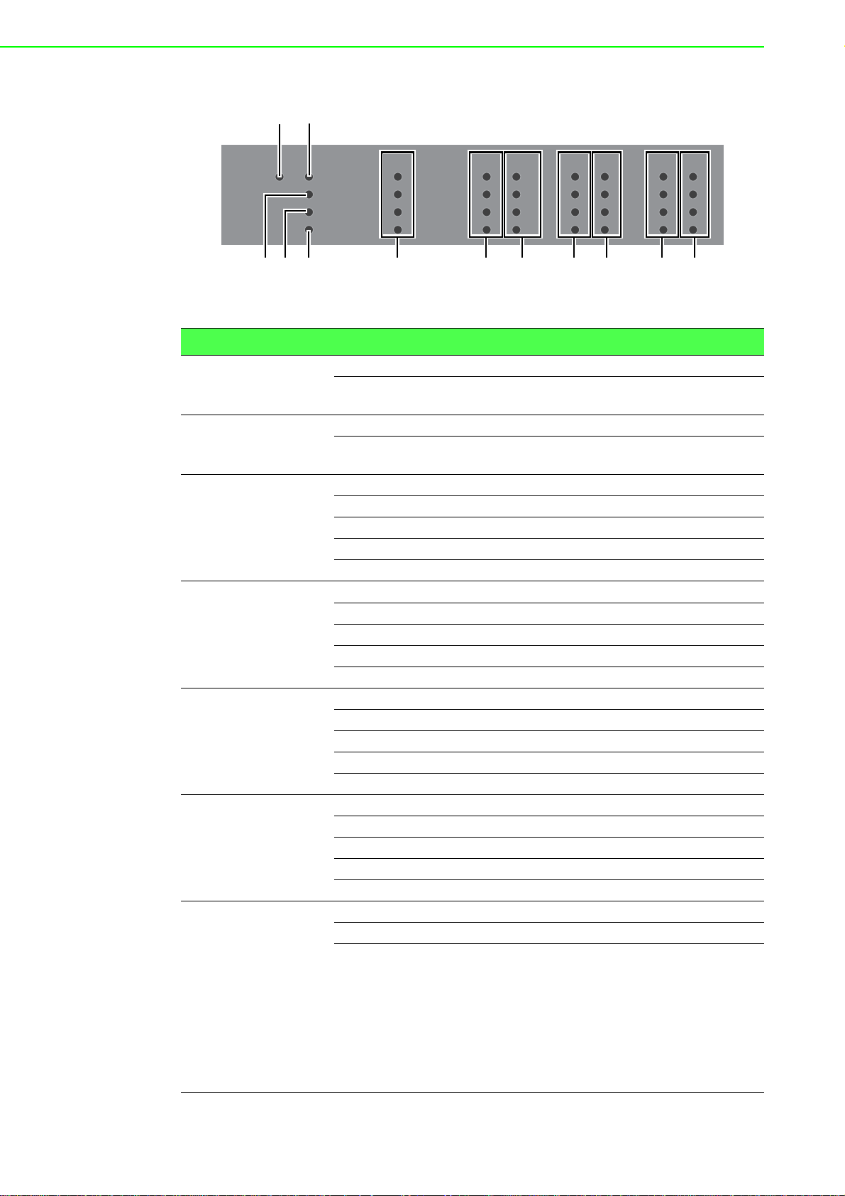
1.3.1.1 System LED Panel
3
12
45 6 6 7 6 7 6 7
PWR 2
No. LED Name LED Color Description
PWR2 Green on Power is being supplied to power input PWR2.
1
PWR1 Green on Power is being supplied to power input PWR1.
2
SYS Green on EKI switch system is ready.
3
CFG Yellow on TBD
4
ALM Red on Defined major policies are detected.
5
DATA Green on Link 1G
6
PoE
7
(only available in
EKI-9516P-LV,
EKI-9516P-HV,
EKI-9512P-LV,
EKI-9512P-HV,
EKI-9516DP-LV,
EKI-9516DP-HV,
EKI-9512DP-LV
and
EKI-9512DP-HV)
DATA DATA PoE DATA PoE DATA PoE
PWR 1
SYS
CFG
ALM
13
14
15
16
9
10
11
12
5
6
7
8
1
2
3
4
Figure 1.5 System LED Panel
Off Power is not being supplied to power input
PWR2.
Off Power is not being supplied to power input
PWR1.
Blink green (1Hz) EKI switch system is under initiating.
Blink green (3Hz) TBD
Blink green (5Hz) TBD
Off Power on processing in U-Boot mode.
Blink yellow (1Hz) Configuration changed, but unsaved.
Blink yellow (3Hz) TBD
Blink yellow (5Hz) TBD
Off Configuration saved.
Blink red (1Hz) Defined minor policies are detected.
Blink red (3Hz) TBD
Blink red (5Hz) TBD
Off Power off or system alarm is cleared or masked.
Blink green ACT 1G
Amber on Link 10/100MB
Blink amber ACT 10/100MB
Off Link down
Green on Providing power over 15. 4 W.
Blink green Pr ov idin g po we r un d er 15. 4 W.
Off User turns off PoE mode at corresponding Giga-
bit Ethernet port.
EKI-9500 Series User Manual 8
Page 28

Chapter 2
2Switch Installation
Page 29

2.1 Installation Guidelines
The following guidelines are provided to optimize the device performance. Review
the guidelines before installing the device.
Make sure cabling is away from sources of electrical noise. Radios, power lines,
and fluorescent lighting fixtures can interference with the device performance.
Make sure the cabling is positioned away from equipment that can damage the
cables.
Operating environment is within the ranges listed range, see “S pecifications” on
page 1.
Relative humidity around the switch does not exceed 95 percent (noncondens-
ing).
Altitude at the installation site is not higher than 10,000 feet.
In 10/100 and 10/100/1000 fixed port devices, the cable length from the switch
to connected devices can not exceed 100 meters (328 feet).
Make sure airflow around the switch and respective vents is unrestricted. With-
out proper airflow the switch can overheat. To prevent performance degradation
and damage to the switch, make sure there is clearance at the top and bottom
and around the exhaust vents.
2.1.1 Connecting Hardware
These instructions explain how to find a proper location for your Modbus Gateways,
and how to connect to the network, hook up the power cable, and conne ct to the EKI9500 Series.
2.2 Verifying Switch Operation
Before installing the device in a rack or on a wall, power on the switch to verify that
the switch passes the power-on self-test (POST). To connect the cabling to the power
source see “Power Supply Installation” on page 12.
At startup (POST), the System LED blinks green, while the remaining LEDs are a
solid green. Once the switch passes POST self-test, the System LED turns green.
The other LEDs turn off and return to their operating status. If the switch fails POST,
the System LED switches to an amber state.
After a successful self-test, power down the switch and disconnect the po wer cabling.
The switch is now ready for installation at its final location.
2.3 Installing the Switch
2.3.1 Wall-Mounting
Note! When installing, make sure to allow for enough space to properly install
the cabling.
1. Locate the installation site and place the switch against the wall, making sure it
is the final installation location.
EKI-9500 Series User Manual 10
Page 30
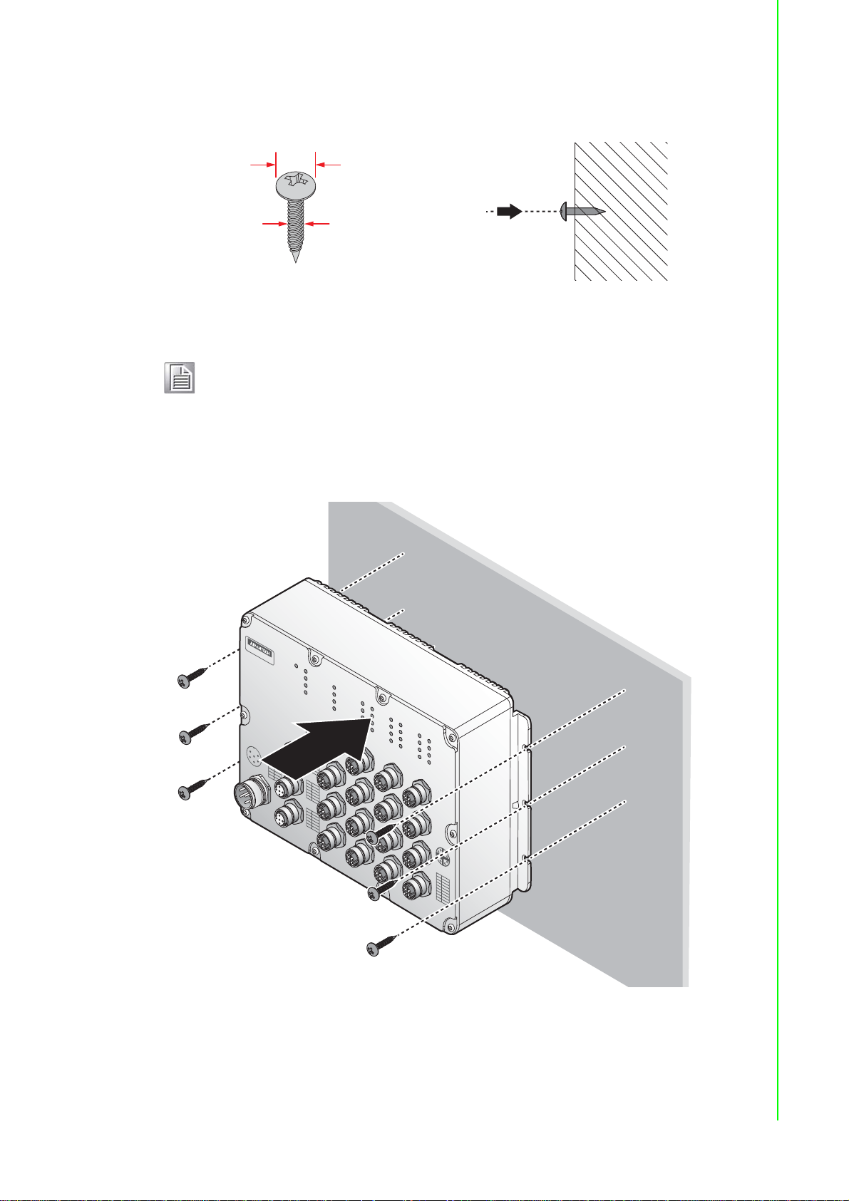
2. Insert the screws into the wall sinks. Leave a 6 mm gap between the wall and
10 mm
4.0 mm
(Max: 4.3mm)
4.0 mm
P
in
D
N
Si
gn
a
l
V
B
US
NC
D
P
G
N
D
1
2
3
4
5
P
in
TX
Si
gna
l
R
X
D
S
R
G
N
D
D
TR
1
2
3
4
5
P
in
P
1
-
N
P
1
-
P
P
2
-
N
P
2
-
P
P
a
i
r
1
2
3
4
5
N
A
P
in
P
ai
r
1
2
3
4
5
6
7
8
D
A
-
D
A
+
D
B
-
D
B
+
D
D
-
D
C
-
D
C
+
D
D
+
2
1
5
3
4
P
i
n
P
WR
G
N
D
N
A
1
2
3
4
5
6
L
1
/
V
+
L
1
/
V
-
L
2
/
V
+
L
2
/
V
-
1
2
5
4
6
3
C
o
n
s
o
le
A
L
M
PoE
D
ATA
PoED
ATA
PoE
D
A
TA
1
2
8
7
6
5
4
3
1
2
3
4
5
6
7
8
9
10
11
12
13
14
15
16
DATA
PWR1
SYS
C
FG
ALM
PWR2
EKI-9516P
P
o
wer
the screw head to allow for wall mount plate insertion.
Figure 2.1 Securing Wall Mounting Screws
Note! Make sure the screws dimensions are suitable for use with the
device.
Do not completely tighten the screws into the wall. A final adjust-
ment may be needed before fully securing the device on the wall.
3. Align the device over the screws on the wall.
4. Install the device on the screws and slide it downward to lock in place, see the
following figure.
5. Once the device is installed on the wall, tighten the screws to secure t he device.
Figure 2.2 Switch Installation
11 EKI-9500 Series User Manual
Page 31

2.4 Power Supply Installation
s
Single DC Power Redundant DC Power
2.4.1 Overview
Warning! Power down and disconnect the power cord before servicing or wiring
the switch.
Caution! Do not disconnect modules or cabling unless the power is first switched
off.
The device only supports the voltage outlined in the type plate. Do not
use any other power components except those specifically designated
for the switch device.
Caution! Disconnect the power cord before installation or cable wiring.
The switches can be powered by using the same DC source used to power other
devices. A DC voltage range of 24 to 110 VDC (PoE) must be applied between the
V1+ terminal and the V1- terminal (PW1), see the following illustrations. A Class 2
power supply is required to maintain a UL60950 panel listing. The chassis ground
screw terminal should be tied to the panel or chassis ground. A redundant power
configuration is supported through a secondary power supply unit to reduce network
down time as a result of power loss.
EKI-9500 Series support 24 to 110 VDC. Dual power inputs are supported and allow
you to connect a backup power source.
P2 P1
Chassis
GND
(pane)
One DC Supply
Figure 2.3 Power Wiring for EKI-9500 Series
2.4.2 Considerations
Take into consideration the following guidelines before wiring the device:
The Terminal Block (CN1) is suitable for 12-24 AWG (3.31 - 0.205 mm
value 7 lb-in.
The cross sectional area of the earthing conductors shall be at least 3.31 mm
Calculate the maximum possible current for each power and common wire.
Make sure the power draw is within limits of local electrical code regulations.
For best practices, route wiring for power and devices on separate paths.
P2 P1
Dual DC Supplies
Chassi
GND
(pane)
2
). Torque
2
.
EKI-9500 Series User Manual 12
Page 32

Do not bundle together wiring with similar electrical characteristics.
Make sure to separate input and output wiring.
Label all wiring and cabling to the various devices for more effective manage-
ment and servicing.
Note! Routing communications and power wiring through the same conduit
may cause signal interference. To avoid interference and signal degradation, route power and communications wires through separate conduits.
2.4.3 Grounding the Device
Caution! Do not disconnect modules or cabling unless the power is first switched
off.
The device only supports the voltage outlined in the type plate. Do not
use any other power components except those specifically designated
for the switch device.
Caution! Before connecting the device properly ground the device. Lack of a
proper grounding setup may result in a safety risk and could be hazardous.
Caution! Do not service equipment or cables during periods of lightning activity.
Caution! Do not service any components unless qualified and authorized to do
so.
Caution! Do not block air ventilation holes.
13 EKI-9500 Series User Manual
Page 33
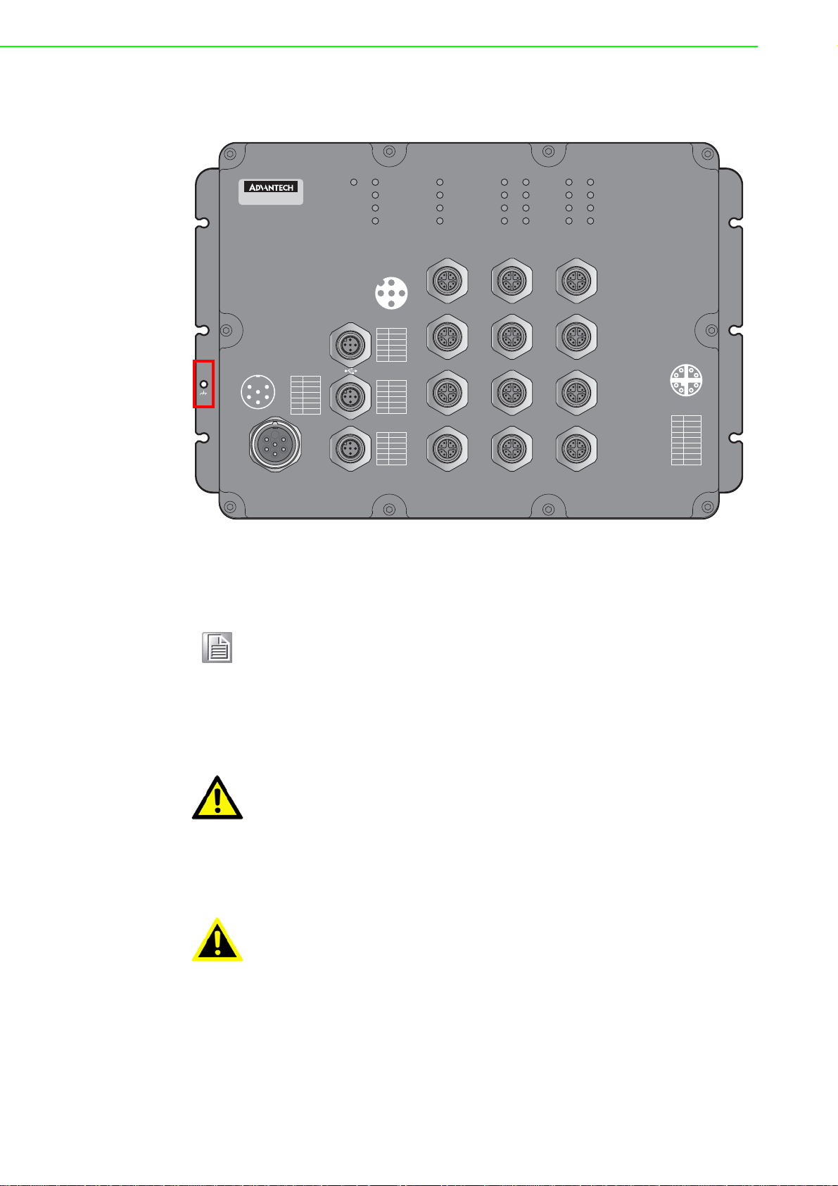
Electromagnetic Interference (EMI) affects the transmission performan ce of a device.
Pin
DN
Signal
VBUS
NC
DP
GND
1
2
3
4
5
Pin
TX
Signal
RX
DSR
GND
DTR
1
2
3
4
5
Pin
P1-N
P1-P
P2-N
P2-P
Pair
1
2
3
4
5
NA
Pin
Pair
1
2
3
4
5
6
7
8
DA
-
DA
+
DB
-
DB
+
DD
-
DC
-
DC
+
DD
+
2
153
4
Pin PWR
GND
NA
1
2
3
4
5
6
L1/V
+
L1/V
-
L2/
V
+
L
2/V
-
1
2
5
4
6
3
Console
ALM
PoEDATAPoEDATA
1
2
8
7
6
5
4
3
1
2
3
4
5
6
7
8
9
10
11
12
DATA
PWR1
SYS
CFG
ALM
PWR2
EKI-9512P
1
2
3
6
3
5
4
Power
By properly grounding the device to earth ground through a drain wire, you can setup
the best possible noise immunity and emissions.
Figure 2.4 Grounding Connection, Chassis Left Side View
By connecting the ground terminal by drain wire to earth ground the switch and chassis can be ground.
Note! Before applying power to the grounded switch, it is advisable to use a
volt meter to ensure there is no voltage difference between the power
supply’s negative output terminal and the grounding point on the switch.
2.4.4 Wiring the Power Inputs
Caution! Do not disconnect modules or cabling unless the power is first switched
off.
The device only supports the voltage outlined in the type plate. Do not
use any other power components except those specifically designated
for the switch device.
Warning! Power down and disconnect the power cord before servicing or wiring
the switch.
To wire the power inputs:
Make sure the power cable is not connected to the switch or the power converter
EKI-9500 Series User Manual 14
before proceeding.
Page 34

1. Remove the protection cap from the power input.
1
2
1
2
5
4
6
3
2
Figure 2.5 Removing the Protection Cap
2. Secure the power cable to the power input.
Figure 2.6 Installing the Power Cable
The power input is now connected to the switch. The switch can be powered on.
2.4.4.1 Standard M23 6-Pin Male Pin Assignment
This section describes the proper connection of the 12, 24, -48, 110, 125 and
250VDC to the DC power connector on the switch. The DC inpu t connector is loca ted
on the left side of the front p anel. The po wer terminals are connected as shown in the
following figure. They are electrically floating inside the unit so that either may be
grounded by the user if desired. The chassis is earthened or ground (GND).
The mating connection to the switch is created through a RD24, female connector.
Simply align the keyed female connector to the male connector and twist the
threaded to secure.
1
Figure 2.7 Standard M23 6-Pin Male DC Power Input Connector
15 EKI-9500 Series User Manual
Page 35

Pin Description
1
2
8
7
6
5
4
3
1
2
3
4
L1/V+
1
L1/V-
2
GND
3
L2/V+
4
L2/V-
5
NA
6
2.5 Connecting the Ethernet Media
2.5.1 Connecting the 10/100/1000BaseT(X)
The managed Ethernet models have four Gigabit Ethernet ports (8-pin shielded M12
connector with X coding) or Fast Ethernet ports (4-pin shielded M12 connector with D
coding) circular connectors. The 10/100/1000BaseT(X) ports located on the switch's
front side are used to connect to Ethernet-enabled devices.
2.5.1.1 M12 X-Coding Connector Pin Assignment
Figure 2.8 10/100/1000BaseT(X) Pin Assignment
Pin Description
DA+
1
DA-
2
DB+
3
DB-
4
DD+
5
DD-
6
DC-
7
DC+
8
2.5.1.2 M12 D-Coding Connector Pin Assignment
Figure 2.9 10/100BaseT(X) Pin Assignment
Pin Description
TD+
1
RD+
EKI-9500 Series User Manual 16
2
Page 36

Pin Description
2
153
4
2
153
4
TD-
3
RD-
4
2.6 Alarm Contact for Monitoring Internal Power
The Alarm Contacts feature, standard on EKI-9500 Series, provides one Form Normally Closed (NC) contact to which the user can attach one set of status monitoring
wires at the green terminal block.
The NC Alarm Contact is held closed when there is power on the mainboard inside of
the switch. This provides a “Hardware Alarm” (labeled H/W) because the NC contacts will open when internal power is lost, either from an external power down condition or by the failure of the power supply inside of the EKI-9500 Series.
2.6.0.1 Pin Assignment
Figure 2.10 Alarm Contact Pin Assignment
Pin Description
P1-N
1
P1-P
2
P2-N
3
P2-P
4
NA
5
2.7 Connecting the Console Terminal
The console port, used to access the managed switch’s software, has an 8-pin M12
(male) port. A console cable with the mating M12 (female) port and both a DB-9 and /
or a USB connector is available for purchase from Advantech.
2.7.0.1 Pin Assignment
Figure 2.11 M12 Console Pin Assignment
Pin Description
TX
1
RX
2
DSR
3
GND
4
DTR
5
17 EKI-9500 Series User Manual
Page 37

2.8 Connecting the USB Terminal
2.8.0.1 Pin Assignment
2
153
4
Figure 2.12 M12 Console Pin Assignment
Pin Description
DN
1
VBUS
2
NC
3
DP
4
GND
5
EKI-9500 Series User Manual 18
Page 38

Chapter 3
3Configuration Utility
Page 39

3.1 First Time Setup
3.1.1 Overview
The Industrial Ethernet Managed Switch is a configurable device that facilitates the
interconnection of Ethernet devices on an Ethernet network. This includes computers, operator interfaces, I/O, controllers, RTUs, PLCs, other switches/hubs or any
device that supports the standard IEEE 802.3 protocol.
This switch has all the capabilities of a store and forward Ethernet switch plus
advanced management features such as SNMP, RSTP and port mirroring. This manual details how to configure the various management parameters in this easy to use
switch.
3.1.2 Introduction
To take full advantage of all the features and resources available from the switch, it
must be configured for your network.
The switch implements Rapid Spanning Tree Protocol (RSTP) and Simple Network
Management Protocol (SNMP) to provide most of the services offered by the switch.
Rapid Spanning Tree Protocol allows managed switches to communicate with each
other to ensure that there exists only one active route between each pair of network
nodes and provides automatic failover to the next available redundant route. A brief
explanation of how RSTP works is given in the Spanning Tree section.
The switch is capable of communicating with other SNMP capable devices on the
network to exchange management information. This statistical/derived information
from the network is saved in the Management Information Base (MIB) of the switch.
The MIB is divided into several different information storage groups. These groups
will be elaborated in detail in the Management and SNMP information section of this
document. The switch implements Internet Group Management Protocol (IGMP) to
optimize the flow of multicast traffic on your network.
The switch supports both port-based and tag-based Virtual LANs for flexible integration with VLAN-aware networks with support for VLAN-unaware devices.
3.1.3 Administrative Interface Access
There are several administrative interfaces to the switch:
1. A graphical web interface accessible via the switch's built-in web server. Both
HTTP and secure HTTPS with SSL are supported.
Note! This is the recommended method for managing the switch.
2. A terminal interface via the RS232/USB port or over the network using telnet or
Secure Shell (SSH).
3. An SNMP interface can be used to read/write many settings.
4. Command Line Interface (CLI) can be used to read/write most settings. Initial
setup must be done using an Ethernet connection (recommended) or the serial
port.
EKI-9500 Series User Manual 20
Page 40

3.1.4 Using the Graphical (Web) Interface
The graphical interface is provided via a web server in the switch and can be
accessed via a web browser such as Opera, Mozilla, or Internet Explorer.
Note! JavaScript must be supported and enabled in your browser for the
graphical interface to work correctly.
HTTP and HTTPS (secure HTTP) are supported for access to the web server. By
default, both protocols are enabled. Either or both may be disabled to secure the
switch. (See the Remote Access Security topic in this section.)
To access the graphical interface, enter a URL like HTTP://192.168.1.1 in your
browser's address bar. Replace “http” with “https” to use secure http and replace
“192.168.1.1” with your switch's IP address if you've changed it from the factory
default.
The web server in the switch uses a signed security certificate. When you access the
server via https, you may see a warning dialog indicating that the certificate was
signed by an unknown authority. This is expected and to avoid this message in the
future you can choose to install the certificate on your computer.
Note! This manual describes and depicts the web user interface in detail. The
terminal interface is not specifically shown but is basically the same.
3.1.5 Configuring the Switch for Network Access
To control and monitor the switch via the network, it must be configured with basic
network settings, including an IP address and subnet mask. Refer to the quick start
guide in Section 1 for how to initially access your switch.
To configure the switch for network access, select [Add Menu Address Here] to reach
the System Settings menu. The settings in this menu control the switch's general network configuration.
DHCP Enabled/Disabled: The switch can automatically obtain an IP address
from a server using the Dynamic Host Configuration Protocol (DHCP). This can
speed up initial set up, as the network administrator does not have to find an
open IP address.
IP Address and subnet mask configuration: The IP address for the switch can
be changed to a user-defined address along with a customized subnet mask to
separate subnets.
Note! Advanced users can set the IP address to 0.0.0.0 to disable the use of
an IP address for additional security. However, any features requiring an
IP address (i.e., web interface, etc.) will no longer be available.
Default Gateway Selection: A Gateway Address is chosen to be the address of
a router that connects two different networks. This can be an IP address or a
Fully Qualified Domain Name (FQDN) such as “domainname.org”.
NTP Server: The IP address or domain name of an NTP (Network Time Proto-
col) server from which the switch may retrieve the current time at startup.
Please note that using a domain name requires that at least one domain name
server be configured.
21 EKI-9500 Series User Manual
Page 41

3.1.6 Configuring the Ethernet Ports
The switch comes with default port settings that should allow you to connect to the
Ethernet Ports with out any necessary configuration. Should there be a need to
change the name of the ports, negotiation settings or flow control settings, you can
do this in the Port Configuration menu. Access this menu by selecting Setup from the
Main menu, and then selecting Main Settings.
Port Name: Each port in the managed switch can be identified with a custom
name. Specify a name for each port here.
Admin: Ports can be enabled or disabled in the managed switch. For ports that
are disabled, they are virtually non-existent (not visible in terms of switch operation or spanning tree algorithm). Choose to enable or disab le a port by selecting
Enabled or Disabled, respectively.
Negotiation: All copper ports and gigabit fiber ports in the managed switch are
capable of autonegotiation such that the fastest bandwidth is selected. Choose
to enable auto-negotiation or use fixed settings. 100Mbps Fiber ports are Fixed
speed only.
Speed/Duplex/Flow Control: The managed switch accepts three local area net-
work Ethernet Standards. The first standard, 10BASE-T, runs 10Mbps with
twisted pair Ethernet cable between network interfaces. The second local area
network standard is 100BASE-T, which runs at 100Mbps over the same twisted
pair Ethernet cable. Lastly, there is 100BASE-F, which enables fast Ethernet
(100Mbps) over fiber.
These options are available:
10h–10 Mbps, Half Duplex
10f –10 Mbps, Full Duplex
100h–100 Mbps, Half Duplex
100f –100 Mbps, Full Duplex
1000f–1000 Mbps, Full Duplex
On managed switches with gigabit combination ports, those ports with have two
rows, a standard row of check boxes and a row labeled “SFP” with radio buttons. The
SFP setting independently sets the speed at which a transceiver will operate if one is
plugged in. Otherwise, the switch will use the fixed Ethernet port and the corresponding settings for it.
Note! When 100f is selected for the SFP of a gigabit combination port, the cor-
responding fixed Ethernet jack will be disabled unless it is changed back
to 1000F.
3.2 Command Line Interface Configuration
3.2.1 Introduction to Command-Line Interface (CLI)
The command-line interface (CLI) is constructed with an eye toward automation of
CLI-based configuration. The interaction is modeled on that used in many Internet
protocols such as Telnet, FTP, and SMTP. After each command is entered and processed, the switch will issue a reply that consists of a numeric status code and a
human-readable explanation of the status.
The general format of commands is:
section parameter [value]
where:
– section is used to group parameters.
EKI-9500 Series User Manual 22
Page 42

– parameter will specify the p arameter within the section. For example, the n et-
work section will have parameters for DHCP, IP address, subnet mask, and
default gateway.
– value is the new value of the parameter. If value is omitted, the current value
is displayed.
Please note that new values will not take effect until explicitly committed.
Sections and parameter names are case sensitive (e.g., “Network” is not the same as
“network”).
Note! Any commands in the CLI Commands section of this chapter, with the
exception of the global commands, must be prefaced with the name of
the section they are in. For example, to change the IP address of the
switch, you would type:
network address <newIP>
3.2.2 Accessing the CLI
To access the CLI interface, establish Ethernet or serial connectivity to the switch.
To connect by Ethernet, open a command prompt window and type:
telnet <switchip> (where <switchip> is the IP address of the switch)
At the login prompt, type “cli” for the username and “admin” for the password. The
switch will respond with “Managed switch configuration CLI ready”.
3.3 Web Browser Configuration
The switch has an HTML based user interface embedded in the flash memory. The
interface offers an easy to use means to manage basic and advanced switch functions. The interface allows for local or remote switch configuration anywhere on the
network. The interface is designed for use with [Internet Explorer (6.0), Chrome,
Firefox].
3.3.1 Preparing for Web Configuration
The interface requires the installation and connectio n of the switch to the existing network. A PC also connected to the network is required to connect to the switch and
access the interface through a web browser. Use this networking information:
IP address: 192.168.1.1
Subnet mask: 255.255.255.0
Default gateway: 192.168.1.254
User name: admin
Password: admin
3.3.2 System Login
Once the switch is installed and connected, power on the switch. The following information guides you through the logging in process.
1. Launch your web browser on the PC.
2. In the browser’s address bar, type the switch’s default IP address (192.168.1.1).
The login screen displays.
3. Enter the user default name and password (admin / admin).
4. Click OK on the login screen to log in.
The main interface displays.
23 EKI-9500 Series User Manual
Page 43

Chapter 4
4Managing Switch
Page 44
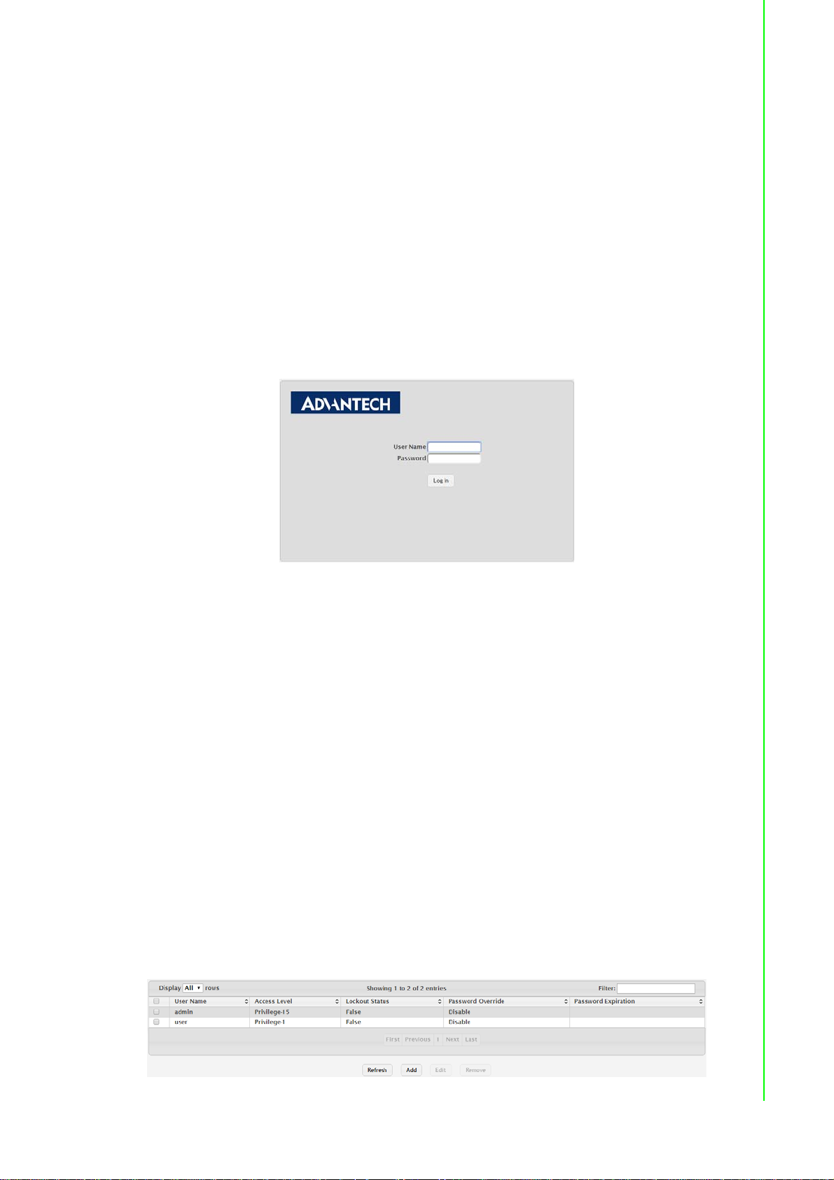
4.1 Log In
To access the login window, connect the device to the network, see “Connecting the
Ethernet Media” on page 16. Once the switch is installed and connected, power on
the switch see the following procedures to log into your switch.
When the switch is first installed, the default network configuration is set to DHCP
enabled. You will need to make sure your network environment supports the switch
setup before connecting it to the network.
1. Launch your web browser on a computer.
2. In the browser’s address bar type in the switch’s default IP address
(192.168.1.1). The login screen displays.
3. Enter the default user name and password (admin/admin) to log into the man-
agement interface. You can change the default password after you have successfully logged in.
4. Click Login to enter the management interface.
Figure 4.1 Login Screen
4.2 Recommended Practices
One of the easiest things to do to help increase the security posture of the network
infrastructure is to implement a policy and standard for secure management. This
practice is an easy way to maintain a healthy and secure network.
After you have performed the basic configurations on your switches, the following is a
recommendation which is considered best practice policy.
4.2.1 Changing Default Password
In keeping with good management and security practices, it is recommended that
you change the default password as soon as the device is functioning and setup correctly. The following details the necessary steps to change the default password.
To change the password:
1. Navigate to System > Users > Accounts.
2. From the User Name menu, select the Admin (default) account and click Edit.
3. In the User Name field, enter admin for this account. It is not necessary to
change the user name, however, a change in the default settings improves the
switch's security.
Figure 4.2 System > Users > Accounts
25 EKI-9500 Series User Manual
Page 45
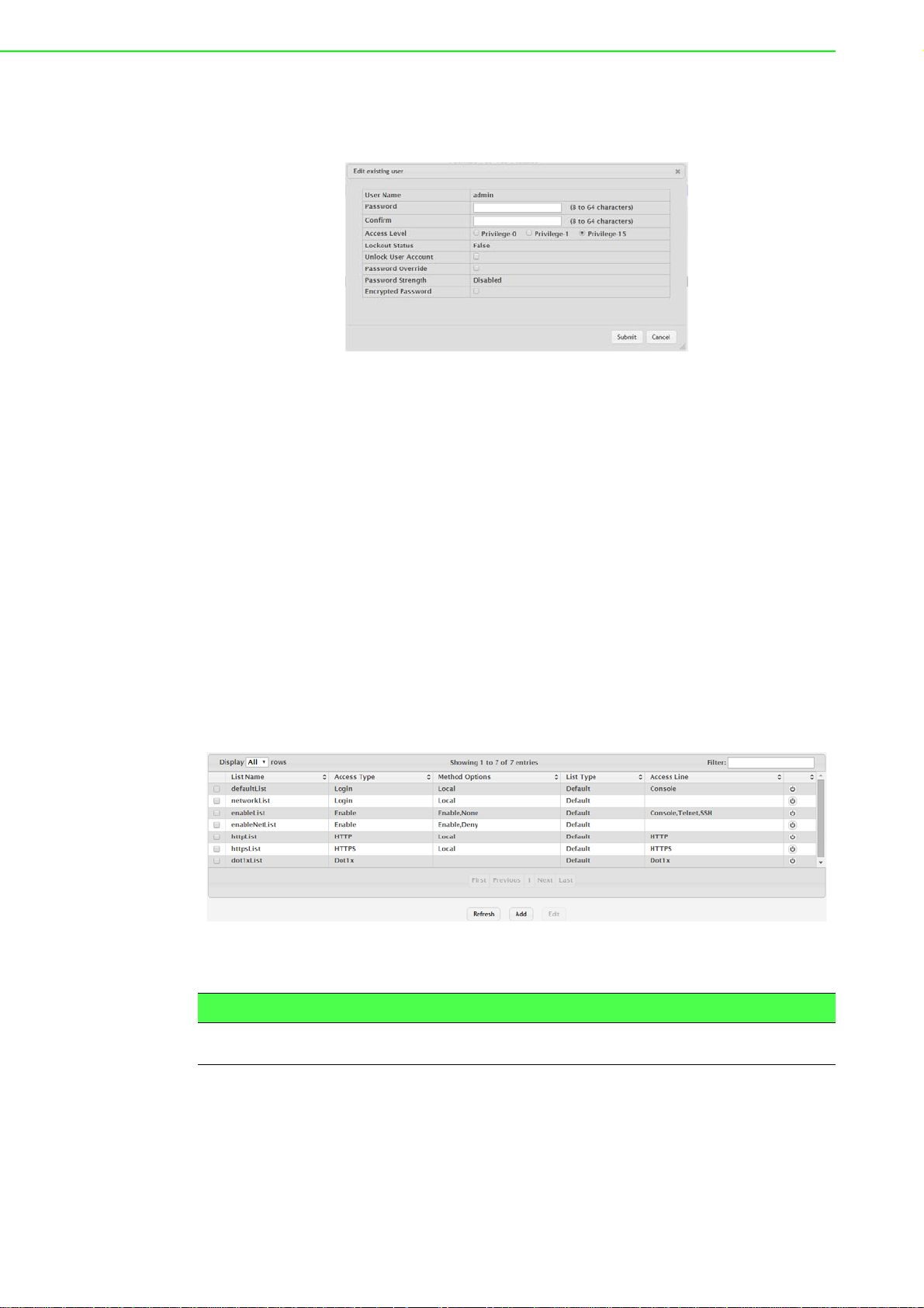
4. In the Password field, type in the new password. Re-type the same password in
the Confirm field.
5. Click Submit to change the current account settings.
After saving all the desired settings, perform a system save (Save Configuration).
The changes are saved.
4.3 System
4.3.1 AAA
Figure 4.3 Changing a Default Password
4.3.1.1 Authentication List
Use the Authentication List Configuration page to view and configure the authentication lists used for management access and port-based (IEEE 802.1X) access to the
system. An authentication list specifies which authentication method(s) to use to validate the credentials of a user who attempts to access the device. Several authentication lists are preconfigured on the system. These are default list s, and they cannot be
deleted.Additionally, the List Name and Access Type settings for the default lists cannot be changed.
To access this page, click System > AAA > Authentication List.
Figure 4.4 System > AAA > Authentication List
The following table describes the items in the previous figure.
Item Description
List Name The name of the authentication list. This field can be configured only
when adding a new authentication list.
EKI-9500 Series User Manual 26
Page 46

Item Description
Access Type The way the user accesses the system. This field ca n be con fig ur ed
only when adding a new authentication list, and only the Login and
Enable access types can be selected. The access types are as follows:
Login: User EXEC-level management access to the command-
line interface (CLI) by using a console connection or a telnet or
SSH session. Access at this level has a limited number of CLI
commands available to view or configure the system.
Enable: Privileged EXEC-level management access to the CLI
by using a console connection or a telnet or SSH session. In
Privileged EXEC mode, read-write users have access to all CLI
commands.
HTTP: Management-level access to the web-based user inter-
face by using HTTP.
Dot1x: Port-based access to the network through a switch port
that is controlled by IEEE 802.1X.
Method Options The method(s) used to authenticate a user who attempts to access
the management interface or net w ork. The possible methods are as
follows:
IAS: Uses the local Internal Authentication Server (IAS) data-
base for 802.1X port-based authentication.
Deny: Denies authentication.
Enable: Uses the locally configured Enable password to verify
the user's credentials.
Line: Uses the locally configured Line password to verify the
user's credentials.
Local: Uses the ID and password in the Local User database to
verify the user's credentials.
Radius: Sends the user's ID and password to the configured
Radius server to verify the user's credentials.
TACACS: Sends the user's ID and password to the configured
TACACS server to verify the user's credentials.
None: No authentication is used.
List Type The type of list, which is one of the following:
Default: The list is preconfigured on the system. This type of list
cannot be deleted, and only the Method Options are configurable.
Configured: The list has been added by a user.
Access Line The access method(s) that use the list for authentication. The settings
for this field are configured on the Authentication Selection page.
Refresh Click Refresh to update the screen.
Add Click Add to add a new authentication list. See the following proce-
dure.
Edit Click Edit to edit the selected entries.
27 EKI-9500 Series User Manual
Page 47

To add a new authentication list:
Click System > AAA > Authentication List > Add.
Figure 4.5 System > AAA > Authentication List > Add
The following table describes the items in the previous figure.
Item Description
Authentication Methods
Available Methods The authentication methods that can be used for the authentication
list. Not all authentication methods are available for all lists. To set the
authentication method, select the method in the Available Methods
field and click the right arrow to move it into the Selected Methods
field.
Selected Methods The authentication methods currently configured for the list. When
multiple methods are in this field, the order in which the meth od s ar e
listed is the order in which the methods will be used to authenticate a
user. If the user fails to be authenticated using the first method, the
device attempts to verify the user's credentials by using the next
method in the list. No authentication methods can be added after
None. To remove a method from this field, select it and click the left
arrow to return it to the Available Methods area.
Submit Click Submit to save the values.
Cancel Click Cancel to close the window.
4.3.1.2 Authentication Selection
Use the Authentication List Selection page to associate an authentication list with
each CLI-based access method (Console, Telnet, and SSH). Each access method
has the following two authentication lists associated with it:
Login: The authentication list to use for User EXEC-level management access
to the CLI. Access at this level has a limited number of CLI commands available
to view or configure the system. The options available in this menu include the
default Login authentication lists as well as any user-configured Login lists.
Enable: The authentication list to use for Privileged EXEC-level management
access to the CLI. In Privileged EXEC mode, read-write users have access to all
CLI commands. The options available in this menu include the default Enable
authentication lists as well as any user-configured Enable lists.
To access this page, click System > AAA > Authentication Selection.
Figure 4.6 System > AAA > Authentication Selection
EKI-9500 Series User Manual 28
Page 48

The following table describes the items in the previous figure.
Item Description
Terminal
Console The Login authentication list and the Enable authentication list to
Telnet The Login authentication list and the Enable authentication list to
SSH The Login authentication list and the Enable authentication list to
Submit Click Submit to save the values and update the screen.
Refresh Click Refresh to update the screen.
Cancel Click Cancel to restore default value.
4.3.1.3 Accounting List
Use the Accounting List Configuration page to view and configure the accounting lists
for users who access the command-line interface (CLI) to manage and monitor the
device. Accounting lists are used to record user activity on the device. The device is
preconfigured with accounting lists. These are default lists, and they cannot be
deleted. Additionally, the List Name and Accounting Type settings for the default lists
cannot be changed.
To access this page, click System > AAA > Accounting List.
apply to users who attempt to access the CLI by using a connection to
the console port.
apply to users who attempt to access the CLI by using a Telnet session.
apply to users who attempt to access the CLI by using a secure shell
(SSH) session.
Figure 4.7 System > AAA > Accounting List
The following table describes the items in the previous figure.
Item Description
Accounting Type The type of accounting list, which is one of the following:
Command: Each CLI command executed by the user , alon g with
the time the command was executed, is recorded and sent to an
external AAA server.
Exec: User login and logout times are recorded and sent to an
external AAA server.
List Name The name of the accounting list. This fie ld can be conf igu red only
when adding a new accounting list.
Record Type Indicates when to record and send information about the user activity:
Star tS top: Accounting notifica tions are sent at the beginning a nd
at the end of an exec session or a user-executed command.
User activity does not wait for the accounting notificat ion to be
recorded at the AAA server.
StopOnly: Accounting notifications are sent at the end of an
exec session or a user-executed command.
29 EKI-9500 Series User Manual
Page 49

Item Description
Method Options The method(s) used to record user activity. The possible methods are
as follows:
TACACS+: Accounting notifications are sent to the configured
TACACS+ server.
Radius: Accounting notifications are sent to the configured
RADIUS server.
List Type The type of accounting list, which is one of the following:
Default: The list is preconfigured on the system. This type of list
cannot be deleted, and only the Method Options and Record
Type settings are configurable.
Configured: The list has been added by a user.
Access Line The access method(s) that use the list for accounting user activity.
The settings for this field are configured on the Accounting Selection
page.
Refresh Click Refresh to update the screen.
Add Click Add to add a new accounting list.
Edit Click Edit to edit the selected entries.
To add a new accounting list:
Click System > AAA > Accounting List > Add.
Figure 4.8 System > AAA > Accounting List > Add
The following table describes the items in the previous figure.
Item Description
Accounting Methods
Available Methods The accounting methods that can be used for the accounting list. To
set the accounting method, select the method in the Available Meth-
ods field and click the right arrow to move it into the Selected Method s
field.
Selected Methods The accounting methods curren tly configured for the list. When multi-
ple methods are in this field, the order in which the methods are listed
is the order in which the methods will be used. If the device is unable
to send accounting notifications by using the first method, the device
attempts to send notifications by using the second metho d. To remove
a method from this field, select it and click the left arrow to return it to
the Available Methods area.
Submit Click Submit to save the values.
Cancel Click Cancel to close the window.
EKI-9500 Series User Manual 30
Page 50

4.3.1.4 Accounting Selection
Use the Accounting List Selection page to associate an accounting list with each
access method. For each access method, the following two accounting lists are associated:
Exec: The accounting list to record user login and logout times.
Commands: The accounting list to record which actions a user takes on the sys-
tem, such as page views or configuration changes. This list also records the
time when the action occurred. For Terminal access methods, this list records
the CLI commands a user executes and when each command is issued.
To access this page, click System > AAA > Accounting Selection.
Figure 4.9 System > AAA > Accounting Selection
The following table describes the items in the previous figure.
Item Description
Terminal The access methods in this section are CLI-based.
Console: The Exec accounting list and the Commands account-
ing list to apply to users who access the CLI by using a connection to the console port.
Telnet: The Exec accounting list and the Commands accounting
list to apply to users who access the CLI by using a Telnet session.
SSH: The Exec accounting list and the Commands accounting
list to apply to users who access the CLI by using a secure shell
(SSH) session.
Hypertext Transfer
Protocol
The access methods in this section are through a web browser.
HTTP: The Exec accounting list and the Commands accounting
list to apply to users who access the web-based management
interface by using HTTP.
HTTPS: The Exec accounting list and the Commands account-
ing list to apply to users who access the web-based manage-
ment interface by using secure HTTP (HTTPS).
Submit Click Submit to save the values and update the screen.
Refresh Click Refresh to update the screen.
Cancel Click Cancel to restore default value.
31 EKI-9500 Series User Manual
Page 51

4.3.2 Advanced Configuration
4.3.2.1 DHCP Server Global
Use the DHCP Server Global Configuration page to configure DHCP global parameters.
To access this page, click System > Advanced Configuration > DHCP Server >
Global.
Figure 4.10 System > Advanced Configuration > DHCP Server > Global
The following table describes the items in the previous figure.
Item Description
Admin Mode Enables or disables the DHCP server administrative mode. When
enabled, the device can be configured to automatically allocate TCP/
IP configurations for clients.
Conflict Logging
Mode
Bootp Automatic
Mode
Ping Packet Count The number of packets the server sends to a pool address to check
Submit Click Submit to save the values and update the screen.
Refresh Click Refresh to update the screen.
Cancel Click Cancel to restore default value.
Enables or disables the logging mode for IP address conflicts. When
enabled, the system stores information IP address conflicts that are
detected by the DHCP server.
Enables or disables the BOOTP automatic mode. When enabled, the
DHCP server supports the allocation of automatic addresses for
BOOTP clients. When disabled the DHCP server supports only static
addresses for BOOTP clients.
for duplication as part of a ping operation. If the server receives a
response to the ping, the address is considered to be in conflict and is
removed from the pool.
Excluded Addresses
Use the DHCP Server Excluded Addresses page to view and configure the IP
addresses the DHCP server should not assign to clients.
To access this page, click System > Advanced Configuration > DHCP Server >
Excluded Addresses.
Figure 4.11 System > Advanced Configuration > DHCP Server > Excluded
Addresses
EKI-9500 Series User Manual 32
Page 52

The following table describes the items in the previous figure.
Item Description
From The IP address to exclude. In a range of addresses, this value is the
lowest address to exclude.
To The highest address to exclude in a range of addresses. If the
excluded address is not part of a range, this field shows the same
value as the From field. When adding a single IP address to exclude,
you can enter the same address specified in the From field or leave
the field with the default value.
Refresh Click Refresh to update the screen.
Add Click Add to add a new excluded address.
Remove Click Remove to remove the selected entries.
To add a new excluded address:
Click System > Advanced Configuration > DHCP Server > Excluded Addresses
> Add.
Figure 4.12 System > Advanced Configuration > DHCP Server > Excluded
Addresses > Add
The following table describes the items in the previous figure.
Item Description
From The IP address to exclude. In a range of addresses, this value is the
lowest address to exclude.
To The highest address to exclude in a range of addresses. If the
excluded address is not part of a range, this field shows the same
value as the From field. When adding a single IP address to exclude,
you can enter the same address specified in the From field or leave
the field with the default value.
Submit Click Submit to save the values.
Cancel Click Cancel to close the window.
Pool Summary
Use the DHCP Server Pool Summary page to view the currently configured DHCP
server pools and to add and remove pools. A DHCP server pool is a set of network
configuration information available to DHCP clients that request the information.
To access this page, click System > Advanced Configuration > DHCP Server >
Pool Summary.
Figure 4.13 System > Advanced Configuration > DHCP Server > Pool Summary
33 EKI-9500 Series User Manual
Page 53

The following table describes the items in the previous figure.
Item Description
Name The name that identifies the DHCP server pool.
Type The type of binding for the pool. The options are:
Manual: The DHCP server assigns a specific IP address to the
client based on the client's MAC address. This type is also
known as Static.
Dynamic: The DHCP server can assign the client any available
IP address within the pool. This type is also known as Automatic.
Undefined: The pool has been created by using the CLI, but the
pool information has not been configured .
Network For a Manual pool, indicates the host IP address to assign the client.
For a Dynamic pool, indicates the network base address.
Lease Time The amount of time the information the DHCP server allocates is
valid.
Refresh Click Refresh to update the screen.
Add Click Add to add a new DHCP server pool.
Remove Click Remove to remove the selected entries.
To add a new DHCP server pool:
Click System > Advanced Configuration > DHCP Server > Pool Summary > Add.
Figure 4.14 System > Advanced Configuration > DHCP Server > Pool Summary
> Add
The following table describes the items in the previous figure.
Item Description
Name The name that identifies the DHCP server pool.
Type of Binding The type of binding for the pool. The options are:
Manual
Dynamic
The binding type you select determines the fields that are available to
configure.
EKI-9500 Series User Manual 34
Page 54

Item Description
Network Base
Address
Network Mask The subnet mask associated with the Network Base Address that sep-
Client Name The system name of the client. The Client Name should not include
Hardware Address
Type
Hardware Address The MAC address of the client. The function is only available for Man-
Client ID The value some DHCP clients send in the Client Identifier field of
Host IP Address The IP address to offer the client. The function is only available for
Host Mask The subnet mask to offer the client. The function is only available for
Lease Expiration
Mode
The network portion of the IP address. A DHCP client can be offered
any available IP address within the defined network as long as it has
not been configured as an excluded address (for dynamic pools only).
arates the network bits from the host bits (for dynamic pools only).
the domain name. The function is only available for Manual pools.
The protocol type (Ethernet or IEEE 802) used by the client's hard-
ware platform. This value is used in response to requests from
BOOTP clients. The function is only available for Manual pools.
ual pools.
DHCP messages. This value is typically identical to the Hardware
Address value. In some systems, such as Microsoft DHCP clients, the
client identifier is required instead of the hardware address. If the client's DHCP request includes the client identifier, the Clie nt ID fiel d on
the DHCP server must contain the same value, and the Hardware
Address Type field must be set to the app ropriate value. Otherwise,
the DHCP server will not respond to the client's request. The function
is only available for Manual pools.
Manual pools.
Manual pools.
Indicates whether the information the server provides to the client
should expire.
Enable: Allows the lease to expire. If you select this option, you
can specify the amount of time the lease is valid in the Lease
Duration field.
Disable: Sets an infinite lease time. For Dynamic bindings, an
infinite lease time implies a lease period of 60 days. For a Manual binding, an infinite lease period never expires.
Lease Duration The number of Days, Hours, and Minutes the lease is valid. This field
cannot be configured if the Lease Expiration Mode is disabled.
Default Router
Address
DNS Server Address The IP addresses of up to two DNS servers the client should use to
Submit Click Submit to save the values.
Cancel Click Cancel to close the window.
The IP address of the router to which the client should send traffic.
The default router should be in the same subnet as the client. To add
additional default routers, use the DHCP Server Pool Configuration
page.
resolve host names into IP addresses. To add additional DNS servers,
use the DHCP Server Pool Configuration page.
Pool Configuration
Use the DHCP Server Pool Configuration page to edit pool settings or to configure
additional settings for existing manual and dynamic pools. The additional settings on
this page are considered advanced parameters because they are not typically used
or configured. The fields that can be configured depend on the Type of Binding that is
selected. The fields that do not apply to the selected binding type are disabled.
35 EKI-9500 Series User Manual
Page 55

To access this page, click System > Advanced Configuration > DHCP Server >
Pool Configuration.
Figure 4.15 System > Advanced Configuration > DHCP Server > Pool
Configuration
The following table describes the items in the previous figure.
Item Description
Pool Name Select the pool to configure. The menu includes all pools that have
been configured on the device.
Type of Binding The type of binding for the pool. The options are:
Manual: The DHCP server assigns a specific IP address to the
client based on the client's MAC address. This type is also
known as Static.
Dynamic: The DHCP server can assign the client any available
IP address within the pool. This type is also known as Automatic.
Network Base
Address
Network Mask The subnet mask associated with the Network Base Address that sep-
Client Name The system name of the client. The Client Name should not include
Hardware Address
Type
Hardware Address The MAC address of the client (for manual pools only).
Client ID The value some DHCP clients send in the Client Identifier field of
Host IP Address The IP address to offer the client (for manual pools only).
Host Mask For manual bindings, this field specifies the subnet mask to be stati-
The network portion of the IP address. A DHCP client can be offered
any available IP address within the defined network as long as it has
not been configured as an excluded address (for dynamic pools only).
arates the network bits from the host bits (for dynamic pools only).
the domain name. This field is optional.
The protocol type (Ethernet or IEEE 802) used by the client's hard-
ware platform. This value is used in response to requests from
BOOTP clients (for manual pools only).
DHCP messages. This value is typically identical to the Hardware
Address value. In some systems, such as Microsoft DHCP clients, the
client identifier is required instead of the hardware address. If the cli-
ent's DHCP request includes the client identifier, the Client ID field on
the DHCP server must contain the same value, and the Hardware
Address Type field must be set to the appropriate value. Otherwise,
the DHCP server will not respond to the client's request (for manual
pools only).
cally assigned to a DHCP client. You can enter a value in Host Mask
or Prefix Length to specify the subnet mask, but do not enter a value
in both fields.
EKI-9500 Series User Manual 36
Page 56

Item Description
Lease Expiration Indicates whether the information the server provides to the client
should expire.
Enable: Allows the lease to expire. If you select this option, you
can specify the amount of time the lease is valid in the Lease
Duration field.
Disable: Sets an infinite lease time. For Dynamic bindings, an
infinite lease time implies a lease period of 60 days. For a Manual binding, an infinite lease period never expires.
Lease Duration The number of Days, Hours, and Minutes the lease is valid. This field
cannot be configured if the Lease Expiration is disabled.
Next Server Address The IP address of the next server the client should contact in th e boot
process. For example, the client might be required to contact a TFTP
server to download a new image file. To configure this field, click
button in the row . To reset the field to the default value, click the Reset
icon in the row.
To configure settings for one or mo re defau lt routers, DN S server s, or
NetBIOS servers that can be used by the client(s) in the pool, use the
buttons available in the appropriate table to perform the following
tasks:
To add an entry to the server list, click button and enter the
IP address of the server to add.
To edit the address of a configured server, click button asso-
ciated with the entry to edit and update the address.
To delete an entry from the list, click button associated with
the entry to remove.
To delete all entries from the list, click button in the heading
row.
Default Router Lists the IP address of each router to which the client(s) in the pool
should send traffic. The default router should be in the same subnet
as the client.
DNS Server Lists the IP address of each DNS server the client(s) in the pool can
contact to perform address resolution.
NetBIOS Server Lists the IP address of each NetBIOS Windows Internet Naming Ser-
vice (WINS) name server that is available for the selected pool.
Submit Click Submit to save the values and update the screen.
Refresh Click Refresh to update the screen.
Cancel Click Cancel to restore default value.
Pool Options
Use the DHCP Server Pool Options page to configure additional DHCP pool options,
including vendor-defined options. DHCP options are collections of data with type
codes that indicate how the options should be used. When a client broadcasts a
request for information, the request includes the option codes that correspond to the
information the client wants the DHCP server to supply.
37 EKI-9500 Series User Manual
Page 57

To access this page, click System > Advanced Configuration > DHCP Server >
Pool Options.
Figure 4.16 System > Advanced Configuration > DHCP Server > Pool Options
The following table describes the items in the previous figure.
Item Description
Pool Name Select the pool to configure. The menu includes all pools that have
been configured on the device.
NetBIOS Node Type The method the client should use to resolve NetBIOS names to IP
addresses. To configure this field, click the Edit icon in the row. To
reset the field to the default value, click the Reset icon in the r ow. The
options are:
B-Node Broadcast: Broadcast only
P-Node Peer-to-Peer: NetBIOS name server only
M-Node Mixed: Broadcast, then NetBIOS name server
H-Node Hybrid: NetBIOS name server, then broadcast
Domain Name The default domain name to configure for all clients in th e selected
pool.
Bootfile Name The name of the default boot image that the client should attempt to
download from a specified boot server.
Option Name Identifies whether the entry is a fixed option or a vendor-defined
option (Vendor).
Option Code The number that uniquely identifies the option.
Option Type The type of data to associate with the Option Code, which can be one
of the following:
ASCII
HEX
IP Address
Option Value The data associated with the Option Code. When adding or editing a
vendor option, the field(s) available for configuring the value depend
on the selected Option Typ e. If the value you configure contains char-
acters that are not allowed by the selected Option T ype , the configura-
tion cannot be applied.
Refresh Click Refresh to update the screen.
Add Vendor Option Click Add Vendor Option to add a new vendor option.
Edit Click Edit to edit the selected entries.
Remove Click Remove to remove the selected entries.
EKI-9500 Series User Manual 38
Page 58

To add a new vendor option:
Click System > Advanced Configuration > DHCP Server > Pool Options > Add
Vendor Option.
Figure 4.17 System > Advanced Configuration > DHCP Server > Pool Options >
Add Vendor Option
The following table describes the items in the previous figure.
Item Description
Option Code The number that uniquely identifies the option.
Option Type The type of data to associate with the Option Code, which can be one
of the following:
ASCII
HEX
IP Address
Submit Click Submit to save the values.
Cancel Click Cancel to close the window.
To edit a new vendor option:
Click System > Advanced Configuration > DHCP Server > Pool Options > Con-
figure Vendor Option.
Figure 4.18 System > Advanced Configuration > DHCP Server > Pool Options >
Configure Vendor Option
The following table describes the items in the previous figure.
Item Description
Option Code The number that uniquely identifies the option.
Option Type The type of data to associate with the Option Code, which can be one
of the following:
ASCII
HEX
IP Address
39 EKI-9500 Series User Manual
Page 59
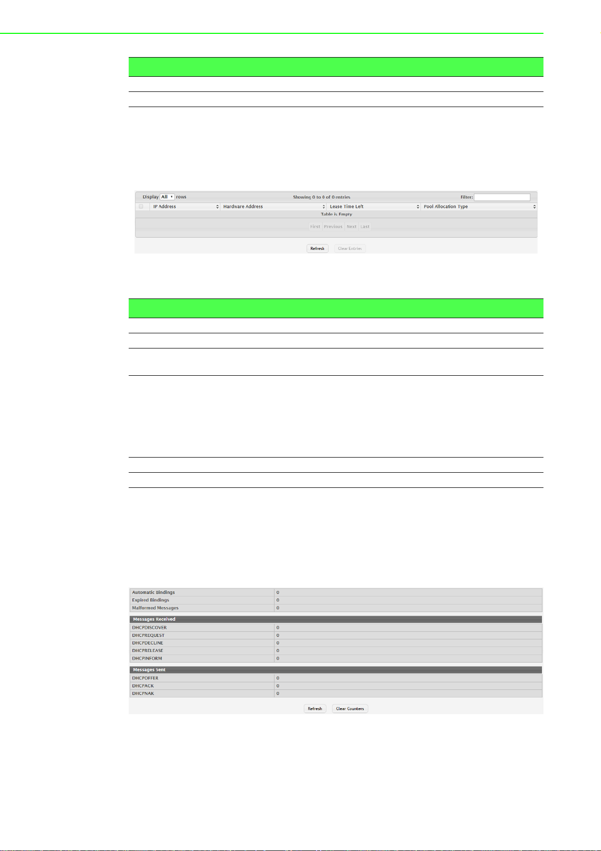
Item Description
Submit Click Submit to save the values.
Cancel Click Cancel to close the window.
Bindings
Use the DHCP Server Bindings page to view information about the IP address bindings in the DHCP server database.
To access this page, click System > Advanced Configuration > DHCP Server >
Bindings.
Figure 4.19 System > Advanced Configuration > DHCP Server > Bindings
The following table describes the items in the previous figure.
Item Description
IP Address The IP Address of the DHCP client.
Hardware Address The MAC address of the DHCP client.
Lease Time Left The amount of time left until the lease expires in days, hours, and min-
utes.
Pool Allocation Type The type of binding used:
Dynamic: The address was allocated dynamically from a pool
that includes a range of IP addresses.
Manual: A static IP address was assigned based on the MAC
address of the client.
Inactive: The pool is not in use.
Refresh Click Refresh to update the screen.
Clear Entries Click Clear Entries to remove a selected entry.
Statistics
The DHCP Server Statistics page displays the DHCP server statistics for the device,
including information about the bindings and DHCP messages. The values on this
page indicate the various counts that have a ccumulated since th ey were last cleared.
To access this page, click System > Advanced Configuration > DHCP Server >
Statistics.
Figure 4.20 System > Advanced Configuration > DHCP Server > Statistics
EKI-9500 Series User Manual 40
Page 60

The following table describes the items in the previous figure.
Item Description
Automatic Bindings The total number of IP addresses from all address pools with auto-
matic bindings that the DHCP server has assigned to DHCP clients.
Expired Bindings The number of IP addresses that the DHCP server has assigned to
DHCP clients that have exceeded the configured lease time.
Malformed Messages
Messages Received
DHCPDISCOVER The number of DHCP discovery messages the DHCP server has
DHCPREQUEST The number of DHCP request messages the DHCP server has
DHCPDECLINE The number of DHCP decline messages the DHCP server has
DHCPRELEASE The number of DHCP release messages the DHCP server has
DHCPINFORM The number of DHCP inform messages the DHCP server has
Messages Sent
DHCPOFFER The number of DHCP offer messages the DHCP server has sent to
DHCP A CK The number of DHCP acknowledgement messa ges the DHCP server
DHCPNAK The number of negative DHCP acknowledgement messages the
Refresh Click Refresh to update the screen.
Clear Counters Click Clear Counters to reset all counters to zero.
The number of messages received from one or more DHCP clients
that were improperly formatted.
received. A DHCP client broadcasts this type of message to discover
available DHCP servers.
received. A DHCP client broadcasts this type of message in response
to a DHCP offer message it received from a DHCP server.
received from clients. A client sends a decline message if the DHCP
client detects that the IP address offered by the DHCP server is
already in use on the network. The server then marks the address as
unavailable.
received from clients. This type of message indicates that a client no
longer needs the assigned address.
received from clients. A client uses this type of message to obtain
DHCP options.
DHCP clients in response to DHCP discovery messages it has
received.
has sent to DHCP clients in response to DHCP request messages it
has received. The server sends this message after the cli ent has
accepted the offer from this particular server. The DHCP acknowledgement message includes information about the lease time and
any other configuration information that the DHCP client has
requested.
DHCP server has sent to DHCP clients. A server might send this type
of message if the client requests an IP address that is already in use
or if the server refuses to renew the lease.
Conflicts
Use the DHCP Server Conflicts Information page to view information on hosts that
have address conflicts; i.e., when the same IP address is assigned to two or more
devices on the network.
41 EKI-9500 Series User Manual
Page 61

To access this page, click System > Advanced Configuration > DHCP Server >
Conflicts.
Figure 4.21 System > Advanced Configuration > DHCP Server > Conflicts
The following table describes the items in the previous figure.
Item Description
IP Address The IP address that has been detected as a duplicate.
Detection Method The method used to detect the conflict, which is one of the following:
Gratuitous ARP: The DHCP client detected the conflict by
broadcasting an ARP request to the address specified in the
DHCP offer message sent by the server. If the client receives a
reply to the ARP request, it declines the offer and reports the
conflict.
Ping: The server detected the conflict by sending an ICMP echo
message (ping) to the IP address before offer ing it to the DHCP
client. If the server receives a response to the ping, the address
is considered to be in conflict and is removed from the pool.
Host Declined: The server received a DHCPDECLINE message
from the host. A DHCPDECLINE message indicates that the
host has discovered that the IP address is already in use on the
network.
Detection Time The time when the conflict was detected in days, hours, minutes and
seconds since the system was last reset (i.e., system up time).
Refresh Click Refresh to update the screen.
Clear Entries Click Clear Entries to clear all of the address conflict entries.
4.3.2.2 DNS
You can use these pages to configure information about DNS servers the network
uses and how the switch/ router operates as a DNS client.
Global
Use the DNS Global Configuration page to configure global DNS settings and to view
DNS client status information.
To access this page, click System > Advanced Configuration > DNS > Configura-
tion.
Figure 4.22 System > Advanced Configuration > DNS > Configuration
EKI-9500 Series User Manual 42
Page 62

The following table describes the items in the previous figure.
Item Description
Admin Mode The administrative mode of the DNS client.
Default Domain
Name
Retry Number The number of times the DNS client should attempt to send DNS que-
Response Timeout
(secs)
Domain List The list of domain names that have been added to the DNS client's
DNS Server A unique IPv4 or IPv6 address used to identify a DNS server. The
Submit Click Submit to save the values and update the screen.
Refresh Click Refresh to update the screen.
Cancel Click Cancel to restore default value.
The default domain name for the DNS client to use to complete
unqualified host names. Domain names are typically composed of a
series of labels concatenated with dots. After a default domain name
is configured, if you enter a host name and do not include the domain
name information, the default domain name is automatically
appended to the host name.
ries to a DNS server on the network.
The number of seconds the DNS client should wait for a response to a
DNS query.
domain list. If a DNS query that includes the default domain name is
not resolved, the DNS client attempts to use the domain names in this
list to extend the hostname into a fully-qualified domain name. The
DNS client uses the entries in the order that they appear in the list.
order in which you add servers determines the precedence of the
server. The DNS server that you add firs t has the hig hest precedence
and will be used before other DNS servers that you add.
IP Mapping
Use the DNS IP Mapping page to configure DNS host names for hosts on the network and to view dynamic DNS entries. The host names are associated with IPv4 or
IPv6 addresses on the network, which are statically assigned to particular hosts.
To access this page, click System > Advanced Configuration > DNS > IP Map-
ping.
Figure 4.23 System > Advanced Configuration > DNS > IP Mapping
The following table describes the items in the previous figure.
Item Description
Entry Type Type of DNS entry:
Static: An en try that has been manually configure d on the
device.
Dynamic: An entry that the device has learned by using a config-
ured DNS server to resolve a hostname.
Host Name The name that identifies the system. For Static entries, specify the
Host Name after you click Add. A host name can contain up to 255
characters if it contains multiple levels in the domain hierarchy, but
each level (the portion preceding a period) can contain a maximum of
63 characters. If the host name you specify is a single level (does not
contain any periods), the maximum number of allowed characters is
63.
43 EKI-9500 Series User Manual
Page 63

Item Description
IP Address The IPv4 or IPv6 address associated with the configured Host Name.
For St atic entr ies, sp ecify th e IP Address after you click Add. You can
specify either an IPv4 or an IPv6 address.
Total Time The number of seconds that the entry will remain in the table. The
function is only available for Dynamic entries.
Elapsed Time The number of seconds that have passed since the entry was added
to the table. When the Elapsed T ime reaches the Total Time, the entry
times out and is removed from the table. The function is only available
for Dynamic entries.
Dynamic Type The type of address in the entry, for example IP or (less common)
X.121. The function is only available for Dynamic entries.
Refresh Click Refresh to update the screen.
Add Click Add to add a new DNS entry.
Remove Click Remove to remove the selected entries.
To add a new DNS entry:
Click System > Advanced Configuration > DNS > IP Mapping > Add.
Figure 4.24 System > Advanced Configuration > DNS > IP Mapping > Add
The following table describes the items in the previous figure.
Item Description
Host Name The name that identifies the system. For Static entries, specify the
Host Name after you click Add. A host name can contain up to 255
characters if it contains multiple levels in the domain hierarchy, but
each level (the portion preceding a period) can contain a maximum of
63 characters. If the host name you specify is a single level (does not
contain any periods), the maximum number of allowed characters is
63.
IP Address The IPv4 or IPv6 address associated with the configured Host Name.
For St atic entries, specify the IP Address after you click Add. You can
specify either an IPv4 or an IPv6 address.
Submit Click Submit to save the values.
Cancel Click Cancel to close the window.
Source Interface Configuration
Use the DNS Source Interface Configuration page to specify the physical or logical
interface to use as the DNS client source interface. When an IP address is configured
on the source interface, this address is used for all DNS communications between
the local DNS client and the remote DNS server. The IP address of the designated
source interface is used in the IP header of DNS management protocol packets. This
allows security devices, such as firewalls, to identify all source packets coming from a
specific device.
EKI-9500 Series User Manual 44
Page 64

To access this page, click System > Advanced Configuration > DNS > Source
Interface Configuration.
Figure 4.25 System > Advanced Configuration > DNS > Source Interface
Configuration
The following table describes the items in the previous figure.
Item Description
Type The type of interface to use as the source interface:
None: The primary IP address of the originating (outbound)
interface is used as the source address.
Interface: The primary IP address of a physical port is used as
the source address.
VLAN: The primary IP address of a VLAN routing interface is
used as the source address.
Interface When the selected T ype is Interface, select the physic al port to use as
the source interface.
VLAN When the selected T ype is VLAN, select the VLAN to use as the
source interface. The menu contains only the VLAN IDs for VLAN
routing interfaces.
Submit Click Submit to save the values and update the screen.
Refresh Click Refresh to update the screen.
Cancel Click Cancel to restore default value.
4.3.2.3 Email Alerts
With the Email alerting feature, log messages can be sent to one or more Email
addresses. You must configure information about the network Simple Mail Transport
Protocol SMTP) server for Email to be successfully sent from the switch.
The pages available from the Email Alerting folder allow you to configure information
about what type of log message are sent via Email and to what address(es) the me ssages are delivered by Email.
Global
Use the Email Alert Global Configuration page to configure the common settings for
log messages emailed by the switch.
To access this page, click System > Advanced Configuration > Email Alerts >
Global.
Figure 4.26 System > Advanced Configuration > Email Alerts > Global
The following table describes the items in the previous figure.
Item Description
Admin Mode Sets the administrative mode of the feature.
From Address Specifies the email address of the sender (the switch).
Enable: The device can send email alerts to the configured
SMTP server.
Disable: The device will not send email alerts.
45 EKI-9500 Series User Manual
Page 65

Item Description
Log Duration
(Minutes)
Submit Click Submit to save the values and update the screen.
Refresh Click Refresh to update the screen.
Cancel Click Cancel to restore default value.
Determines how frequently the non critical messages are sent to the
SMTP server.
Test
Use the Email Alert Test page to verify that the Email alert settings are configured
properly. After you specify the settings on this page and click Submit, the device will
use the configured SMTP server to send an Email to the configured Email addresses.
To access this page, click System > Advanced Configuration > Email Alerts >
Test.
Figure 4.27 System > Advanced Configuration > Email Alerts > Test
The following table describes the items in the previous figure.
Item Description
Test Message Type Specifies the type of message to test for email alert functionality.
Test Message Body Specifies the text contained in the body of the email alert test mes-
sage.
Submit Click Submit to save the values and update the screen.
Refresh Click Refresh to update the screen.
Cancel Click Cancel to restore default value.
Server
Use the Email Alert Server Configuration page to configure information about up to
three SMTP (mail) servers on the network that can handle Email alerts sent from the
switch.
To access this page, click System > Advanced Configuration > Email Alerts >
Server.
Figure 4.28 System > Advanced Configuration > Email Alerts > Server
The following table describes the items in the previous figure.
Item Description
Address Shows the IPv4/IPv6 address or host name of the SMTP server that
handles email alerts that the device sends.
Port Specifies the TCP port that email alerts are sent to on the SMTP
server.
Security Specifies the type of authentication to use with the mail server, which
can be TLSv1 (SMTP over SSL) or None (no authentication is
required).
User Name If the Security is TLSv1, this field specifies the user name required to
access the mail server.
EKI-9500 Series User Manual 46
Page 66

Item Description
Password If the Security is TLSv1, this field specifies the password associated
with the configured user name for mail server access. When adding or
editing the server, you must retype the password to confirm that it is
entered correctly.
Refresh Click Refresh to update the screen.
Add
Edit Click Edit to edit the selected entries.
Remove Click Remove to remove the selected entries.
Click Add to add a new
Email server.
To add a new Email server:
Click System > Advanced Configuration > Email Alerts > Server > Add.
Figure 4.29 System > Advanced Configuration > Email Alerts > Server > Add
The following table describes the items in the previous figure.
Item Description
Security Specifies the type of authentication to use with the mail server, which
can be TLSv1 (SMTP over SSL) or None (no authentication is
required).
Port
User Name If the Security is TLSv1, this field specifies the user name required to
Password If the Security is TLSv1, this field specifies the password associated
Submit Click Submit to save the values.
Cancel Click Cancel to close the window.
Specifies the TCP port that
server.
access the mail server.
with the configured user name for mail server access. When adding or
editing the server, you must retype the password to confirm that it is
entered correctly.
Email alerts are sent to on the SMTP
Statistics
Use the Email Alert Statistics page to view information about Email alerts sent from
the switch.
To access this page, click System > Advanced Configuration > Email Alerts > Sta-
tistics.
Figure 4.30 System > Advanced Configuration > Email Alerts > Statistics
The following table describes the items in the previous figure.
Item Description
Number of Emails
Sent
The number of email alerts that were successfully sent since the
counters were cleared or the system was reset.
47 EKI-9500 Series User Manual
Page 67
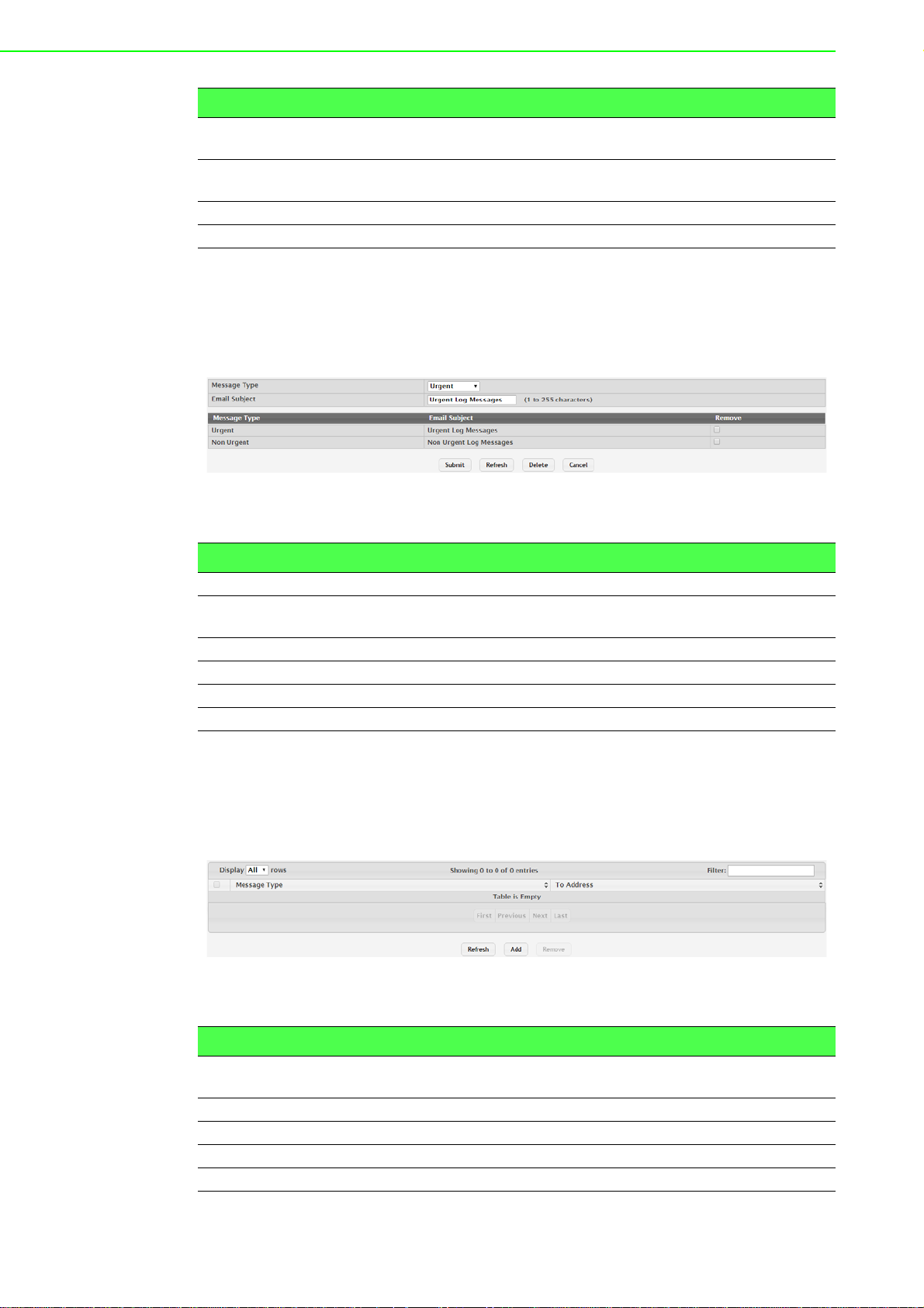
Item Description
Number of Emails
Failed
Time Since Last
Email Sent
Refresh Click Refresh to update the screen.
Clear Counters Click Clear Counters to reset all counters to zero.
The number of email alerts that failed to be sent since the counters
were cleared or system was reset.
The amount of time in days, hours, minutes, and seconds that has
passed since the last email alert was successfully sent.
Subject
Use the Email Alert Subject Configuration page to configure the subject line of the
Email alert messages sent from the switch.
To access this page, click System > Advanced Configuration > Email Alerts >
Subject.
Figure 4.31 System > Advanced Configuration > Email Alerts > Subject
The following table describes the items in the previous figure.
Item Description
Message Type Select the message type with the subject to edit.
Email Subject Specify the text to be displayed in the subject of the email alert mes-
sage for the selected message type.
Submit Click Submit to save the values and update the screen.
Refresh Click Refresh to update the screen.
Delete Click Delete to delete the selected message type.
Cancel Click Cancel to restore default value.
Address
Use the Email Alert To Address Configuration page to configure the Email addresses
to which alert messages sent.
To access this page, click System > Advanced Configuration > Email Alerts >
Address.
Figure 4.32 System > Advanced Configuration > Email Alerts > Address
The following table describes the items in the previous figure.
Item Description
Message Type Specifies whether to send urgent, non urgent, or both types of email
alert message to the associated address.
To Address The valid email address of an email alert recipient.
Refresh Click Refresh to update the screen.
Add Click Add to add a new email alert to address.
Remove Click Remove to remove the selected entries.
EKI-9500 Series User Manual 48
Page 68

To add a new Email alert to address:
Click System > Advanced Configuration > Email Alerts > Address > Add.
Figure 4.33 System > Advanced Configuration > Email Alerts > Address > Add
The following table describes the items in the previous figure.
Item Description
To Address
Message Type
Submit Click Submit to save the values.
Cancel Click Cancel to close the window.
4.3.2.4 ISDP
The Industry Standard Discovery Protocol (ISDP) is a proprietary Layer 2 network
protocol which inter-operates with Cisco devices running the Cisco Discovery Protocol (CDP). ISDP is used to share information between neighboring devices. FASTPATH software participates in the CDP protocol and is able to both discover and be
discovered by other CDP supporting devices.
Global
Use the ISDP Global Configuration page to configure global settings for the Industry
Standard Discovery Protocol (ISDP) feature. ISDP is a proprietary Layer 2 network
protocol that interoperates with the Cisco Discovery Protocol (CDP). ISDP is used to
share information between neighboring devices (routers, bridges, access servers,
and switches).
To access this page, click System > Advanced Configuration > ISDP > Global.
The valid
Specifies whether to send urgent, non urgent, or both types of
alert message to the associated address.
Email address of an Email alert recipient.
Email
Figure 4.34 System > Advanced Configuration > ISDP > Global
The following table describes the items in the previous figure.
Item Description
ISDP Mode The administrative mode of ISDP on the device. When the mode is
enabled, the device sends ISDP announcements out of each ISDPenabled network interface that has a link partner.
ISDP V2 Mode The administrative mode of ISDP version 2 on the device. When the
mode is enabled, the device sends ISDPv2 announcements out of
each ISDP-enabled network interfac e th at has a link partner.
Message Interval
(Seconds)
The number of seconds to wait between ISDP packet transmissions.
49 EKI-9500 Series User Manual
Page 69

Item Description
Hold Time Interval
(Seconds)
Device ID The identification information the device advertises to its neighbors in
Device ID Format
Capability
Device ID Format The current format of the device ID.
Submit Click Submit to save the values and update the screen.
Refresh Click Refresh to update the screen.
Cancel Click Cancel to restore default value.
The number of seconds the neighbor device should co nsider the in for-
mation it receives in an ISDP packet to be valid.
the ISDP packets.
The possible formats that the device can use for identification pur-
poses.
Cache Table
Use the ISDP Cache Table page to view information about other devices the switch
has discovered through the ISDP.
To access this page, click System > Advanced Configuration > ISDP > Cache
Table.
Figure 4.35 System > Advanced Configuration > ISDP > Cache Table
The following table describes the items in the previous figure.
Item Description
Device ID The ID of the neighbor device as advertised in the ISDP message.
The ID could be a host name, serial number, product name, MAC
address, or some other type of information that identifies the neighbor
device.
Interface The local interface that is connected to the neighbor. The ISDP mes-
sage was received on this interface.
IP Address The (first) network-layer address reported in the address TLV of the
most recently received ISDP message from the neighbor.
Version The firmware version running on the neighbor device, as advertised in
the ISDP message.
Hold Time The number of secon ds the info rmation received in an ISDP packet is
considered valid. The timer restarts each time a new ISDP packet is
received from the neighbor. If the value reaches 0, the device is con-
sidered to be disconnected, and the entry ages out.
Capability The functional capabilities advertised by the neighbor. For example, a
neighbor might advertise itself as a switch, router, or host.
Platform The hardware platform information advertised by the neighbor. The
neighbor's ISDP packet might included information such as the name
of the manufacturer or product model.
Port ID The port on the neighbor device from which the ISDP packet was
sent. This is the port that is directly connected to the loc al interf ace
identified in the Interface field.
Protocol Version The protocol version of the ISDP packet sent by the neighbor.
Last Time Changed The amount of time that has passed since the entry was last modified.
Refresh Click Refresh to update the screen.
Clear Click Clear to remove the selected entry.
EKI-9500 Series User Manual 50
Page 70

Interface
Use the ISDP Interface Configuration page to configure the ISDP settings for each
interface.
To access this page, click System > Advanced Configuration > ISDP > Interface.
Figure 4.36 System > Advanced Configuration > ISDP > Interface
The following table describes the items in the previous figure.
Item Description
Interface The interface on which ISDP can be enabled or disabled. In the Edit
ISDP Mode window, this field identifies the interfaces that are being
configured.
ISDP Mode The administrative mode of ISDP on the interface. When ISDP is
enabled globally and on an interface, the interface periodically sends
ISDP messages to its directly connected link partner.
Refresh Click Refresh to update the screen.
Edit Click Edit to edit the selected entries.
Statistics
The ISDP Statistics page displays statistical information about the ISDP packets sent
and received by the device. The transmit statistics provide information about the
ISDP packets sent by all ISDP-enabled interfaces. The receive statistics provide
information about the ISDP packets received from neighbor devices connected to
ISDP-enabled interfaces.
To access this page, click System > Advanced Configuration > ISDP > Statistics.
Figure 4.37 System > Advanced Configuration > ISDP > Statistics
The following table describes the items in the previous figure.
Item Description
Packets Received The total number of ISDP packets received by the device.
Packets Transmitted The total number of ISDP packets transmitted by the device.
ISDPv1 Packets
Received
The total number of ISDP version 1 packets received by the device.
51 EKI-9500 Series User Manual
Page 71
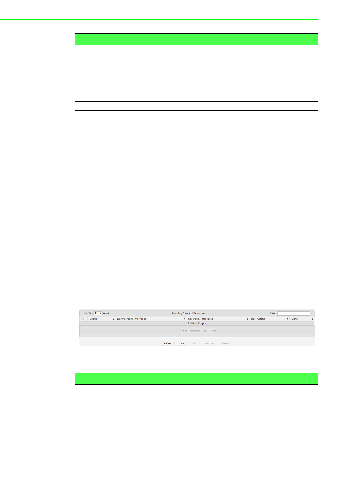
Item Description
ISDPv1 Packets
Transmitted
ISDPv2 Packets
Received
ISDPv2 Packets
Transmitted
Bad Header The total number of ISDP packets received with bad headers.
Checksum Error The total number of ISDP packets received with checksum errors.
Transmission Failure The total number of ISDP packets that the device attempted to trans-
Invalid Format Packets Received
Table Full The number of times a neighbor entry was not added to the ISDP
ISDP IP Address
Table Full
Refresh Click Refresh to update the screen.
Clear Click Clear to reset all statistic to zero.
4.3.2.5 Link Dependency
The link dependency feature provides the ability to enable or disable one or more
ports based on the link state of one or more different ports. With link dependency
enabled on a port, the link state of that port is dependent on the link state of another
port. For example, if port A is dependent on port B and the switch detects a link loss
on port B, the switch automatically brings down the link on port A. When the link is
restored to port B, the switch automatically restores the link to port A.
Group
Use the Link Dependency Group Status page to configure link dependency groups.
Link dependency allows the link status of one interface to be dependent on the link
status of another interface. Link state groups define the interface link dependency.
To access this page, click System > Advanced Configuration > Link Dependency
> Group.
The total number of ISDP version 1 p acket s transmitted b y the device.
The total number of ISDP version 2 packets received by the device.
The total number of ISDP version 2 p acket s transmitted b y the device.
mit but failed to do so.
The total number of ISDP packets received with an invalid ISDP
packet format.
cache table because the local database was full.
The number of times the IP address of a neighbor could not be added
to the neighbor entry because the IP address table was full.
Figure 4.38 System > Advanced Configuration > Link Dependency > Group
The following table describes the items in the previous figure.
Item Description
Group The unique link dependency group identifier.
Downstream Inter-
faces
Upstream Interfaces The set of interfaces that other interfaces are dependent on.
EKI-9500 Series User Manual 52
The set of interfaces dependent on other interfaces.
Page 72

Item Description
Link Action The action performed on downstream interfaces when the upstream
interfaces are down, which can be one of the following:
Up: Downstream interfaces are up when upstream interfaces
are down.
Down: Downstream interfaces go down when upstream inter-
faces are down.
State The group state, which can be one of the following:
Up: Link action is up and no upstream interfaces have their link
up, or link action is down and there are upstrea m inte rfaces tha t
have their link up.
Down: Link is down when the above conditions are not true.
Refresh Click Refresh to update the screen.
Add Click Add to add a new group.
Edit Click Edit to edit the selected entries.
Remove Click Remove to remove the selected entries.
Details Click Detail to open the Group Entry Details window.
To add a new group:
Click System > Advanced Configuration > Link Dependency > Group > Add.
Figure 4.39 System > Advanced Configuration > Link Dependency > Group >
Add
The following table describes the items in the previous figure.
Item Description
Available Interfaces The interfaces that can be added to the group. An interface defined as
an upstream interface cannot be defined as a downstream interface in
the same link state group or in a differ ent group. Similarly, an interface
defined as a downstream interface cannot be defined as an upstream
interface. To move an interface between the Available Interfaces and
Downstream Interfaces or Upstream Interfaces fields, click the inter-
face (or CTRL + click to select multiple interfaces), and then click the
appropriate arrow to move the selected interfaces to the desired field.
53 EKI-9500 Series User Manual
Page 73

Item Description
Submit Click Submit to save the values.
Cancel Click Cancel to close the window.
4.3.2.6 Protection Denial of Service
Use the Denial of Service (DoS) Configuration page to configure DoS control. FASTPATH SMB software provides support for classifying and blocking specific types of
DoS attacks. You can configure your system to monitor and block these types of
attacks:
To access this page, click System > Advanced Configuration > Protection >
Denial of Service.
Figure 4.40 System > Advanced Configuration > Protection > Denial of Service
The following table describes the items in the previous figure.
Item Description
TCP Settings
First Fragment Enable this option to allow the device to drop packets that have a TCP
header smaller than the value configured in the Min TCP Hdr Size
field.
TCP Port Enable this option to allow the device to drop packets that have the
TCP source port equal to the TCP destination port.
UDP Port Enable this option to allow the device to drop packets that have the
UDP source port equal to the UDP destination port.
SIP=DIP Enable this option to allow the device to drop packets that have a
source IP address equal to the destination IP address.
SMAC=DMAC Enable this option to allow the device to drop packets that have a
source MAC address equal to the destination MAC address.
TCP FIN and URG
and PSH
TCP Flag and
Sequence
TCP SYN Enable this option to allow the device to drop packets that have TCP
TCP SYN and FIN Enable this option to allow the device to drop packets that have TCP
Enable this option to allow the device to drop packets that have TCP
Flags FIN, URG, and PSH set and a TCP Sequence Number equal to
0.
Enable this option to allow the device to drop packets that have TCP
control flags set to 0 and the TCP sequence number set to 0.
Flags SYN set.
Flags SYN and FIN set.
EKI-9500 Series User Manual 54
Page 74

Item Description
TCP Fragment Enable this option to allow the device to drop packets that have a TCP
payload where the IP payload length minus the IP header size is less
than the minimum allowed TCP header size.
TCP Offset Enable this option to allow the device to drop packets that have a TCP
header Offset set to 1.
Min TCP Hdr Size The minimum TCP header size allowed. If First Fragment DoS pre-
vention is enabled, the device will drop packets that have a TCP
header smaller than this configured value.
ICMP Settings
ICMP Enable this option to allow the device to dr op ICMP p ackets that have
a type set to ECHO_REQ (ping) and a payload size greater than the
ICMP payload size configured in the Max ICMPv4 Size field.
Max ICMPv4 Size The maximum allowed ICMPv4 packet size. If ICMP DoS prevention
is enabled, the device will drop ICMPv4 ping packets that have a size
greater then this configured maximum ICMPv4 packet size.
ICMPv6 Enable this option to allow the device to drop ICMP packets that have
a type set to ECHO_REQ (ping) and a payload size greater than the
ICMP payload size configured in the Max ICMPv6 Size field.
Max ICMPv6 Size The maximum allowed IPv6 ICMP packet size. If ICMP DoS preven-
tion is enabled, the switch will drop IPv6 ICMP ping packets that have
a size greater than this configured maximum ICMPv6 packet size.
ICMP Fragment Enable this option to allow the device to drop fragmented ICMP pack-
ets.
Submit Click Submit to save the values and update the screen.
Refresh Click Refresh to update the screen.
Cancel Click Cancel to restore default value.
4.3.2.7 sFlow Agent
The sFlow Agent Summary page shows information about the sFlow agent on the
device. sFlow is an industry standard technology for monitoring high-speed switched
and routed networks. The sFlow agent can monitor network traffic on each port and
generate sFlow data to send to a centralized sFlow receiver (also known as a collector).
To access this page, click System > Advanced Configuration > sFlow > Agent.
The following table describes the items in the previous figure.
Item Description
Version Identifies the version and implementation of the sF low agent. Th e ver -
Agent Address The IP address associated with the sFlow agent.
Refresh Click Refresh to update the screen.
Figure 4.41 System > Advanced Configuration > sFlow > Agent
sion string has the following structure: MIB Version; Organization;
Software Version.
Receiver
Use the sFlow Receiver Configuration page to view and to edit the sFlow receiver
settings. The sFlow receiver collects and analyzes information sent by the sFlow
55 EKI-9500 Series User Manual
Page 75
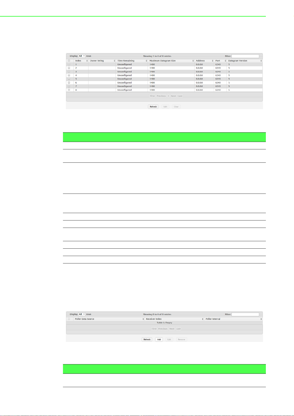
agent on the device. The sFlow agent can send packet sampling data to multiple
sFlow receivers on the network.
To access this page, click System > Advanced Configuration > sFlow > Receiver.
Figure 4.42 System > Advanced Configuration > sFlow > Receiver
The following table describes the items in the previous figure.
Item Description
Index The receiver for which data is displayed or configured.
Owner String The entity making use of this sFlow receiver table entry. If this field is
blank, the entry is currently unclaimed.
Time Remaining The time (in seconds) remaining before the sampler is released and
stops sampling. A value of 0 essentiality means the receiver is not
configured. When configuring the sFlow receiver settings, you must
select the Timeout Mode option before you can configure a Timeout
Value.
Maximum Datagram
Size
Address The IP address of the sFlow receiver.
Port The destination UDP port for sFlow datagrams.
Datagram Version The version of sFlow datagrams that the sFlow agent should send to
Refresh Click Refresh to update the screen.
Edit Click Edit to edit the selected entries.
Clear Click Clear to clear the selected entry.
The maximum number of data bytes that can be sent in a single sample datagram. The receiver should also be set to this value to avoid
fragmentation of the sFlow datagrams.
the sFlow receiver.
Poller
Use the sFlow Poller Configuration page to add, remove, or edit a counter poller
instance on a port (data source). Configuring a poller inst ance allows the sFlow agent
to perform periodic counter sampling on a specified port and efficiently export counters to an sFlow receiver.
To access this page, click System > Advanced Configuration > sFlow > Poller.
Figure 4.43 System > Advanced Configuration > sFlow > Poller
The following table describes the items in the previous figure.
Item Description
Poller Data Source The sFlowDataSource for this sFlow poller . The sFlow agent su pports
physical ports as sFlow data sources.
EKI-9500 Series User Manual 56
Page 76
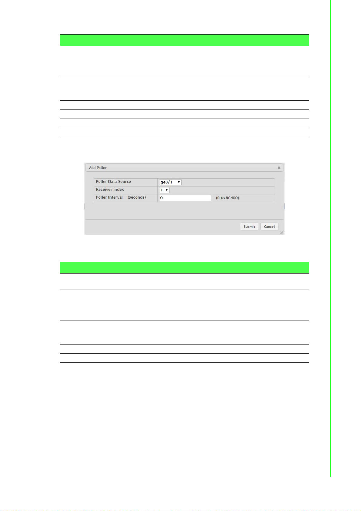
Item Description
Receiver Index The sFlowReceiver for this sFlow counter poller. The specified
Receiver Index must be associated with an active sFlow receiver. If a
receiver expires, all pollers associated with the receiver will also
expire.
Poller Interval The maximum nu m be r of seconds between successiv e samples of
the counters associated with this data source. A sampling inte rval of 0
disables counter sampling.
Refresh Click Refresh to update the screen.
Add Click Add to add a new poller data.
Edit Click Edit to edit the selected entries.
Remove Click Remove to remove the selected entries.
To add a new poller data:
Click System > Advanced Configuration > sFlow > Poller > Add.
Figure 4.44 System > Advanced Configuration > sFlow > Poller > Add
The following table describes the items in the previous figure.
Item Description
Poller Data Source The sFlowDataSource for this sFlow poller. The sFlow agent supports
physical ports as sFlow data sources.
Receiver Index The sFlowReceiver for this sFlow counter poller. The specified
Receiver Index must be associated with an active sFlow receiver. If a
receiver expires, all pollers associated with the receiver will also
expire.
Poller Interval (Sec-
onds)
Submit Click Submit to save the values.
Cancel Click Cancel to close the window.
The maximum number of seconds between successive samples of
the counters associated with this data source. A sampling inte rval of 0
disables counter sampling.
Sampler
Use the sFlow Sampler Configuration page to add, remove, or edit an sFlow sampler
instance on a port (data source). Configuring a sampler instance allows the sFlow
agent to perform statistical packet-based sampling of switched or routed packet
flows. Packet flow sampling creates a steady, but random, stream of sFlow datagrams that are sent to the sFlow receiver.
57 EKI-9500 Series User Manual
Page 77

To access this page, click System > Advanced Configuration > sFlow > Sampler.
Figure 4.45 System > Advanced Configuration > sFlow > Sampler
The following table describes the items in the previous figure.
Item Description
Sampler Data Source The sFlowDataSource for this sFlow sampler. The sFlow agent sup-
ports physical ports as sFlow data sources.
Receiver Index The sFlowReceiver for this sFlow sampler. The specified Receiver
Index must be associated with an active sFlow receiver. If a receiver
expires, all samplers associated with the receiver will also expire.
Sampling Rate The statistical sampling rate for packet sampling from this source. A
sampling rate of 0 disables sampling.
Maximum Header
Size
Refresh Click Refresh to update the screen.
Add Click Add to add a new sampler data.
Edit Click Edit to edit the selected entries.
Remove Click Remove to remove the selected entries.
The maximum number of bytes that should be copied from a sampled
packet.
To add a new sampler data:
Click System > Advanced Configuration > sFlow > Sampler > Add.
Figure 4.46 System > Advanced Configuration > sFlow > Sampler > Add
The following table describes the items in the previous figure.
Item Description
Sampler Data Source The sFlowDataSource for this sFlow sampler. The sFlow agent sup-
ports physical ports as sFlow data sources.
Receiver Index The sFlowReceiver for this sFlow sampler. The specified Receiver
Index must be associated with an active sFlow receiver. If a receiver
expires, all samplers associated with the receiver will also expire.
Sampling Rate The statistical sampling rate for packet sampling from this source. A
sampling rate of 0 disables sampling.
Maximum Header
Size
Submit Click Submit to save the values.
Cancel Click Cancel to close the window.
The maximum number of bytes that should be copied from a sampled
packet.
EKI-9500 Series User Manual 58
Page 78

Source Interface Configuration
Use the sFlow Source Interface Configuration page to specify the physical or logical
interface to use as the sFlow client source interface. When an IP address is configured on the source interface, this address is used for all sFlow communications
between the local sFlow client and the remote sFlow server. The IP address of the
designated source interface is used in the IP header of sFlow management protocol
packets. This allows security devices, such as firewalls, to identify all source packets
coming from a specific device.
To access this page, click System > Advanced Configuration > sFlow > Source
Interface Configuration.
Figure 4.47 System > Advanced Configuration > sFlow > Source Interface
Configuration
The following table describes the items in the previous figure.
Item Description
Type The type of interface to use as the source interface:
None: The primary IP address of the originating (outbound)
interface is used as the source address.
Interface: The primary IP address of a physical port is used as
the source address.
VLAN: The primary IP address of a VLAN routing interface is
used as the source address.
Interface When the selected T ype is Interface, select the physic al port to use as
the source interface.
VLAN ID When the selected Type is VLAN, select the VLAN to use as the
source interface. The menu contains only the VLAN IDs for VLAN
routing interfaces.
Submit Click Submit to save the values and update the screen.
Refresh Click Refresh to update the screen.
Cancel Click Cancel to restore default value.
4.3.2.8 SNMP Community
Access rights are managed by defining communities on the SNMPv1, 2 Community
page. When the community names are changed, access rights are also changed.
SNMP Communities are defined only for SNMP v1 and SNMP v2.
Use the SNMP Community Configuration page to enable SNMP and Authentication
notifications.
To access this page, click System > Advanced Configuration > SNMP > Commu-
nity.
Figure 4.48 System > Advanced Configuration > SNMP > Community
59 EKI-9500 Series User Manual
Page 79

The following table describes the items in the previous figure.
Item Description
Community Name Community name used in SNMPv1/v2 packets. This is configured in
the client and identifies the access the user may connect with.
Security Name Identifies the secur ity en tr y that ass oc i at es co mm unit ies and Groups
for a specific access type.
Group Name Identifies the group associated with this community entry.
IP Address Specifies the IP address that can connect with this community.
Refresh Click Refresh to update the screen.
Add Community Click Add Community to add a new SNMP community.
Add Community
Group
Remove Click Remove to remove the selected entries.
Click Add Community Group to add a new SNMP community group.
To add a new SNMP community:
Click System > Advanced Configuration > SNMP > Community > Add Commu-
nity.
Figure 4.49 System > Advanced Configuration > SNMP > Community > Add
Community
The following table describes the items in the previous figure.
Item Description
Community Name Community name used in SNMPv1/v2 packets. This is configured in
the client and identifies the access the user may connect with.
Community Access Specifies the access control policy for the community.
Community View S pecifies the community view for the community. If the value is empty,
then no access is granted.
IP Address Specifies the IP address that can connect with this community.
Submit Click Submit to save the values.
Cancel Click Cancel to close the window.
EKI-9500 Series User Manual 60
Page 80
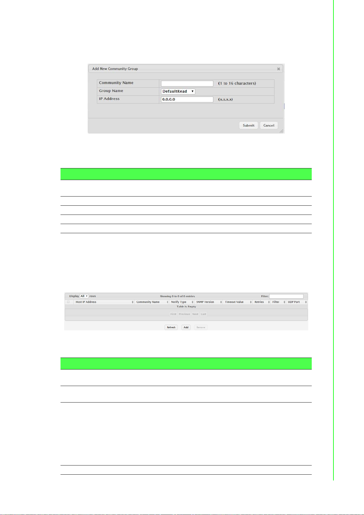
To add a new SNMP community group:
Click System > Advanced Configuration > SNMP > Community > Add Commu-
nity Group.
Figure 4.50 System > Advanced Configuration > SNMP > Community > Add
Community Group
The following table describes the items in the previous figure.
Item Description
Community Name Community name used in SNMPv1/v2 packets. This is configured in
the client and identifies the access the user may connect with.
Group Name Identifies the Group associated with this Community entry.
IP Address Specifies the IP address that can connect with this community.
Submit Click Submit to save the values.
Cancel Click Cancel to close the window.
Trap Receiver v1/v2
Use the SNMP v1/v2 Trap Receivers page to configure settings for each SNMPv1 or
SNMPv2 management host that will receive notifications about traps generated by
the device. The SNMP management host is also known as the SNMP trap receiver.
To access this page, click System > Advanced Configuration > SNMP > Trap
Receiver v1/v2.
Figure 4.51 System > Advanced Configuration > SNMP > Trap Receiver v1/v2
The following table describes the items in the previous figure.
Item Description
Host IP Address The IP address of the SNMP management host that will receive traps
generated by the device.
Community Name The name of the SNMP community that includes the SNMP manage-
ment host and the SNMP agent on the device.
Notify Type The type of SNMP notification to send the SNMP management host:
Inform: An SNMP message that notifies the host when a certain
event has occurred on the device. The message is acknowledged by the SNMP management host. This type of notification
is not available for SNMPv1.
Trap: An SNMP message that notifies the host when a certain
event has occurred on the device. The message is not acknowledged by the SNMP management host.
SNMP Version The version of SNMP to use, which is either SNMPv1 or SNMPv2.
61 EKI-9500 Series User Manual
Page 81

Item Description
Timeout Value The number of seconds to wait for an acknowledgment from the
SNMP management host before resending an inform message.
Retries The numbe r of times to resend an inform message that is not
acknowledged by the SNMP management host.
Filter The name of the filter for the SNMP management host. The filter is
configured by using the CLI and defines which MIB objects to include
or exclude from the view. This field is optional.
UDP Port The UDP port on the SNMP management host that will receive the
SNMP notifications. If no value is specified when configuring a
receiver, the default UDP port value is used.
Refresh Click Refresh to update the screen.
Add Click Add to add a new SNMP trap receiver.
Remove Click Remove to remove the selected entries.
To add a new SNMP trap receiver:
Click System > Advanced Configuration > SNMP > Trap Receiver v1/v2 > Add.
Figure 4.52 System > Advanced Configuration > SNMP > T rap Re ceiver v1/v2 >
Add
The following table describes the items in the previous figure.
Item Description
Host IP Address The IP address of the SNMP management host that will receive traps
generated by the device.
Community Name The name of the SNMP community that includes the SNMP manage-
ment host and the SNMP agent on the device.
Notify Type The type of SNMP notification to send the SNMP management host:
Inform: An SNMP message that notifies the host when a certain
event has occurred on the device. The message is acknowledged by the SNMP management host. This type of notification
is not available for SNMPv1.
Trap: An SNMP message that notifies the host when a certain
event has occurred on the device. The message is not acknowl-
edged by the SNMP management host.
SNMP Version The version of SNMP to use, which is either SNMPv1 or SNMPv2.
Retries The numbe r of times to resend an inform message that is not
acknowledged by the SNMP management host.
Timeout Value (Seconds)
The number of seconds to wait for an acknowledgment from the
SNMP management host before resending an inform message.
EKI-9500 Series User Manual 62
Page 82

Item Description
Filter The name of the filter for the SNMP management host. The filter is
configured by using the CLI and defines which MIB objects to include
or exclude from the view. This field is optional.
UDP Port The UDP port on the SNMP management host that will receive the
SNMP notifications. If no value is specified when configuring a
receiver, the default UDP port value is used.
Submit Click Submit to save the values.
Cancel Click Cancel to close the window.
Trap Receiver v3
Use the SNMP v3 Trap Receivers page to configure settings for each SNMPv3 management host that will receive notifications about traps generated by the device. The
SNMP management host is also known as the SNMP trap receiver.
To access this page, click System > Advanced Configuration > SNMP > Trap
Receiver v3.
Figure 4.53 System > Advanced Configuration > SNMP > Trap Receiver v3
The following table describes the items in the previous figure.
Item Description
Host IP Address The IP address of the SNMP management host that will receive traps
generated by the device.
User Name The name of the SNMP user that is authorized to receive the SNMP
notification.
Notify Type The type of SNMP notification to send the SNMP management host:
Trap: An SNMP message that notifies the host when a certain
event has occurred on the device. The message is not acknowledged by the SNMP management host.
Inform: An SNMP message that notifies the host when a certain
event has occurred on the device. The message is acknowledged by the SNMP management host.
Security Level The security level associated with the SNMP user, which is one of the
following:
No Auth No Priv: No authentication and no data encryption (no
security).
Auth No Priv: Authentication, but no data encryption. With this
security level, users send SNMP messages that use an MD5
key/password for authen tication, but not a DES key/password
for encryption.
Auth Priv: Authentication and data encryption. With this security
level, users send an MD5 key/password for authentication and a
DES key/password for encryption.
Timeout Value The numbe r of second s to wa it for an ack nowle dg m en t fr om the
SNMP receiver before resending an inform message.
Retries The number of times to resend an inform message that is not
acknowledged by the SNMP receiver.
Filter The name of the filter for the SNMP management host. The filter is
configured by using the CLI and defines which MIB objects to include
or exclude from the view. This field is optional.
63 EKI-9500 Series User Manual
Page 83

Item Description
UDP Port The UDP port on the SNMP management host that will receive the
SNMP notifications. If no value is specified when configuring a
receiver, the default UDP port value is used.
Refresh Click Refresh to update the screen.
Add Click Add to add a new SNMP trap receiver.
Remove Click Remove to remove the selected entries.
To add a new SNMP trap receiver:
Click System > Advanced Configuration > SNMP > Trap Receiver v3 > Add.
Figure 4.54 System > Advanced Configuration > SNMP > Trap Receiver v3 >
Add
The following table describes the items in the previous figure.
Item Description
Host IP Address The IP address of the SNMP management host that will receive traps
generated by the device.
User Name The name of the SNMP user that is authorized to receive the SNMP
notification.
Notify Type The type of SNMP notification to send the SNMP management host:
Inform: An SNMP message that notifies the host when a certain
event has occurred on the device. The message is acknowledged by the SNMP management host.
Trap: An SNMP message that notifies the host when a certain
event has occurred on the device. The message is not acknowledged by the SNMP management host.
Security Level The security level ass ociat ed with the SNMP user, which is one of the
following:
No Auth No Priv: No authentication and no data encryption (no
security).
Auth No Priv: Authentication, but no data encryption. With this
security level, users send SNMP messages that use an MD5
key/password for authentication, but not a DES key/password
for encryption.
Auth Priv: Authentication and data encryption. With this security
level, users send an MD5 key/password for authentication and a
DES key/password for encryption.
Retries The numbe r of times to resend an inform message that is not
acknowledged by the SNMP receiver.
EKI-9500 Series User Manual 64
Page 84

Item Description
Timeout Value (Seconds)
Filter The name of the filter for the SNMP management host. The filter is
UDP Port The UDP port on the SNMP management host that will receive the
Submit Click Submit to save the values.
Cancel Click Cancel to close the window.
The number of seconds to wait for an acknowledgm en t fr om the
SNMP receiver before resending an inform message.
configured by using the CLI and defines which MIB objects to include
or exclude from the view. This field is optional.
SNMP notifications. If no value is specified when configuring a
receiver, the default UDP port value is used.
Supported MIBs
The SNMP Supported MIBs page lists the MIBs that the system currently supports.
To access this page, click System > Advanced Configuration > SNMP > Sup-
ported MIBs.
Figure 4.55 System > Advanced Configuration > SNMP > Supported MIBs
The following table describes the items in the previous figure.
Item Description
Name The RFC number, if applicable, followed by the defined name of the
MIB.
Description The RFC title, or a brief description of the MIB.
Refresh Click Refresh to update the screen.
Access Control Group
Use the SNMP Access Control Group page to configure SNMP access control
groups. These SNMP groups allow network managers to assign different levels of
authorization and access rights to specific device features and their attributes. The
SNMP group can be referenced by the SNMP community to provide security and
context for agents receiving requests and initiating traps as well as for management
systems and their tasks. An SNMP agent will not respond to a request from a management system outside of its configured group, but an agent can be a member of
multiple groups at the same time to allow communication with SNMP managers from
different groups. Several default SNMP groups are preconfigured on the system.
65 EKI-9500 Series User Manual
Page 85

To access this page, click System > Advanced Configuration > SNMP > Access
Control Group.
Figure 4.56 System > Advanced Configuration > SNMP > Access Control Group
The following table describes the items in the previous figure.
Item Description
Group Name The name that identifies the SNMP group.
Context Name The SNMP context associated with the SNMP group and its views. A
user or a management application specifies the context name to get
the performance information from the MIB objects associated with that
context name. The Context EngineID identifies the SNMP entity that
should process the request (the physical router), and the Context
Name tells the agent in which context it should search for the ob jec ts
requested by the user or the management application.
SNMP Version The SNMP version associated with the group.
Security Level The security level associated with the group, which is one of the fol-
lowing:
No Auth No Priv: No authentication and no data encryption (no
security). This is the only Security Level available for SNMPv1
and SNMPv2 groups.
Auth No Priv: Authentication, but no data encryption. With this
security level, users send SNMP messages that use an MD5
key/password for authentication, but not a DES key/password
for encryption.
Auth Priv: Authentication and data encryption. With this security
level, users send an MD5 key/password for authentication and a
DES key/password for encryption.
Read The level of read access rights for the group. The menu includes the
available SNMP views. When adding a group, select the check box to
allow the field to be configured, then select the desired view that
restricts management access to viewing the contents of the agent.
Write The level of write access rights for the group. The menu includes the
available SNMP views. When adding a group, select the check box to
allow the field to be configured, then select the desired view that per-
mits management read-write access to the contents of the agent but
not to the community.
Notify The level of notify access rights for the group. The menu includes the
available SNMP views. When adding a group, select the check box to
allow the field to be configured, then select the desired view that per-
mits sending SNMP traps or informs.
Refresh Click Refresh to update the screen.
Add Click Add to add a new access control group.
Remove Click Remove to remove the selected entries.
EKI-9500 Series User Manual 66
Page 86

To add a new access control group:
Click System > Advanced Configuration > SNMP > Access Control Group >
Add.
Figure 4.57 System > Advanced Configuration > SNMP > Access Control Group
> Add
The following table describes the items in the previous figure.
Item Description
Access Control Group
Group Name The name that identifies the SNMP group.
SNMP Version The SNMP version associated with the group.
Security Level The security level associated with the group, which is one of the fol-
lowing:
No Auth No Priv: No authentication and no data encryption (no
security). This is the only Security Level available for SNMPv1
and SNMPv2 groups.
Auth No Priv: Authentication, but no data encryption. With this
security level, users send SNMP messages that use an MD5
key/password for authen tication, but not a DES key/password
for encryption.
Auth Priv: Authentication and data encryption. With this security
level, users send an MD5 key/password for authentication and a
DES key/password for encryption.
Context Name The SNMP context associated with the SNMP group and its views. A
user or a management application specifies the context name to get
the performance information from the MIB object s associated with that
context name. The Context EngineID identifies the SNMP entity that
should process the request (the physical router), and the Context
Name tells the agent in which context it should search for the objects
requested by the user or the management application.
Group Access Rights
Read The level of read access rights for the group. The menu includes the
available SNMP views. When adding a group, select the check box to
allow the field to be configured, then select the desired view that
restricts management access to viewing the contents of the agent.
67 EKI-9500 Series User Manual
Page 87

Item Description
Write The level of write access rights for the group. The menu includes the
available SNMP views. When adding a group, select the check box to
allow the field to be configured, then select the desired view that permits management read-write access to the contents of the agent but
not to the community.
Notify The level of notify access rights for the group. The menu includes the
available SNMP views. When adding a group, select the check box to
allow the field to be configured, then select the desired view that per-
mits sending SNMP traps or informs.
Submit Click Submit to save the values.
Cancel Click Cancel to close the window.
User Security Model
The SNMP User Security Model page provides the capability to configure the SNMP
V3 user accounts.
To access this page, click System > Advanced Configuration > SNMP > User
Security Model.
Figure 4.58 System > Advanced Configuration > SNMP > User Security Model
The following table describes the items in the previous figure.
Item Description
User Name Specifies the name of the SNMP user being added for th e User-based
Security Model (USM). Each user name must be unique within the
SNMP agent user list. A user name cannot contain any leading or
embedded blanks.
Group Name A SNMP group is a group to which hosts running the SNMP service
belong. A group name parameter is simply the name of that group by
which SNMP communities are identified. The use of a group name
provides some security and context for agents receiving req uest s and
initiating traps and does the same for management systems and their
tasks. An SNMP agent won't respond to a request from a manage-
ment system outside its configured group, but an agent can be a
member of multiple groups at the same time. This allows for commu-
nications with SNMP managers from different groups.
Engine ID Each SNMPv3 agent has an engine ID that uniquely identifies the
agent in the device. If given this entry will be used only for packets
whose engine id is this. This field takes an hexadecimal string in the
form 0102030405.
Authentication Specifies the authentication protocol to be used on authenticated
messages on behalf of the specified user.
SHA: SHA protocol will be used.
MD5: MD5 protocol will be used.
None: No authentication will be used for this user.
Privacy Specifies the privacy protocol to be used on encrypted messages on
behalf of the specified user. This parameter is only valid if the Authen-
tication method parameter is not NONE.
DES: DES protocol will be used.
None: No privacy protocol will be used.
EKI-9500 Series User Manual 68
Page 88

Item Description
Refresh Click Refresh to update the screen.
Add Click Add to add a new SNMP user.
Remove Click Remove to remove the selected entries.
To add a new SNMP user:
Click System > Advanced Configuration > SNMP > User Security Model > Add.
Figure 4.59 System > Advanced Configuration > SNMP > User Security Model >
Add
The following table describes the items in the previous figure.
Item Description
Engine ID Type Specifies the engine ID type to be used.
Local
Remote
Engine ID Each SNMPv3 agent has an engine ID that uniquely identifies the
agent in the device. If given this entry will be used only for packets
whose engine id is this. This field takes an hexadecimal string in the
form 0102030405.
User Name Specifies the name of the SNMP user being added for the User-based
Security Model (USM). Each user name must be unique within the
SNMP agent user list. A user name cannot contain any leading or
embedded blanks.
Group Name A SNMP group is a group to which hosts running the SNMP service
belong. A group name parameter is simply the name of that group by
which SNMP communities are identified. The use of a group name
provides some security and context for agents receivin g request s and
initiating traps and does the same for management systems and thei r
tasks. An SNMP agent won't respond to a request from a management system outside its configured group, but an agent can be a
member of multiple groups at the same time. This allows for communications with SNMP managers from different groups.
Authentication
Method
Specifies the authentication protocol to be used on authenticated
messages on behalf of the specified user.
SHA: SHA protocol will be used.
MD5: MD5 protocol will be used.
None: No authentication will be used for this user.
Password Specifies the password used to generate the key to be used in
authenticating messages on behalf of this user. This parame ter must
be specified if the Authentication method parameter is not NONE.
69 EKI-9500 Series User Manual
Page 89

Item Description
Privacy Specifies the privacy protocol to be used on encrypted messages on
behalf of the specified user. This parameter is only valid if the Authen-
tication method parameter is not NONE.
DES: DES protocol will be used.
None: No privacy protocol will be used.
Authentication Key Specifies the password used to generate the key to be used in
encrypting messages to and from this user. This parameter must be
specified if the Privacy parameter is not NONE.
Submit Click Submit to save the values.
Cancel Click Cancel to close the window.
Source Interface Configuration
Use the SNMP Trap Source Interface Configuration page to specify the physical or
logical interface to use as the SNMP client source interface. When an IP address is
configured on the source interface, this address is used for all SNMP communications between the local SNMP client and the remote SNMP server. The IP address of
the designated source interface is used in the IP header of SNMP management protocol packets. This allows security devices, such as firewalls, to identify all source
packets coming from a specific device.
To access this page, click System > Advanced Configuration > SNMP > Source
Interface Configuration.
Figure 4.60 System > Advanced Configuration > SNMP > Source Interface
Configuration
The following table describes the items in the previous figure.
Item Description
Type The type of interface to use as the source interface:
None: The primary IP address of the originating (outbound)
interface is used as the source address.
Interface: The primary IP address of a physical port is used as
the source address.
VLAN: The primary IP address of a VLAN routing interface is
used as the source address.
Interface When the selected Type is Interface, select the physica l port to use as
the source interface.
VLAN ID When the selected Type is VLAN, select the VLAN to use as the
source interface. The menu contains only the VLAN IDs for VLAN
routing interfaces.
Submit Click Submit to save the values and update the screen.
Refresh Click Refresh to update the screen.
Cancel Click Cancel to restore default value.
Server Configuration
Use the SNMP Server Configuration page to view and modify the SNMP Server settings on the device. A user having sufficient privilege level may change the values
shown on this page.
EKI-9500 Series User Manual 70
Page 90
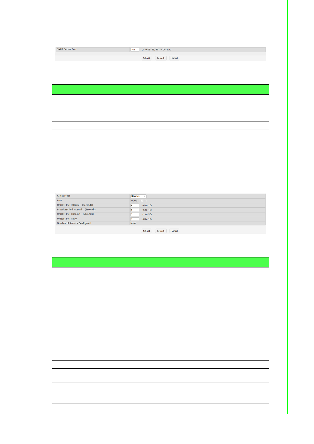
To access this page, click System > Advanced Configuration > SNMP > Server
Configuration.
Figure 4.61 System > Advanced Configuration > SNMP > Server Configuration
The following table describes the items in the previous figure.
Item Description
SNMP Server Port The UDP port number on which the SNMP server listens for request s.
Submit Click Submit to save the values and update the screen.
Refresh Click Refresh to update the screen.
Cancel Click Cancel to restore default value.
4.3.2.9 SNTP Global Configuration
Use the SNTP Global Configuration page to view and adjust SNTP parameters.
To access this page, click System > Advanced Configuration > SNTP > Global
Configuration.
Changing this value may cause existing SNMP transactions to cease
communicating with the device until the client applications are reconfigured to use the new port number.
Figure 4.62 System > Advanced Configuration > SNTP > Global Configuration
The following table describes the items in the previous figure.
Item Description
Client Mode Specifies the mode of operation of SNTP Client. An SNTP client may
operate in one of the following modes:
Disable: SNTP is not operational. No SNTP requests are sent
from the client nor are any received SNTP messages processed.
Unicast: SNTP operates in a point-to-point fashion. A unicast cli-
ent sends a request to a designated serv er at its unicast addre ss
and expects a reply from which it can determine the time and,
optionally the round-trip delay and local clock offset relative to
the server.
Broadcast: SNTP operates in the same manner as multicast
mode but uses a local broadcast address instead of a multicast
address. The broadcast address has a single subnet scope
while a multicast address has Internet wide scope.
Port Specifies the local UDP port to listen for responses/broadcasts.
Unicast Poll Interval
(Seconds)
Broadcast Poll Inter-
val (Seconds)
Specifies the interval, in seconds, between unicast poll requests
expressed as a power of two when configured in unicast mode.
Specifies the interval, in seconds, between broadcast poll requests
expressed as a power of two when configured in broadcast mode.
Broadcasts received prior to the expiry of this interval are discarded.
71 EKI-9500 Series User Manual
Page 91

Item Description
Unicast Poll Timeout
(Seconds)
Unicast Poll Retry Specifies the number of times to retry a request to an SNTP server
Number of Servers
Configured
Submit Click Submit to save the values and update the screen.
Refresh Click Refresh to update the screen.
Cancel Click Cancel to restore default value.
Specifies the timeout value, in seconds, to wait for an SNTP response
when configured in unicast mode.
after the first time-out before attempting to use the next configured
server when configured in unicast mode.
Specifies th e number of current valid unicast server e ntries configured
for this client.
Global Status
Use the SNTP Global Status page to view information about the system's SNTP client.
To access this page, click System > Advanced Configuration > SNTP > Global
Status.
Figure 4.63 System > Advanced Configuration > SNTP > Global Status
The following table describes the items in the previous figure.
Item Description
Version Specifies the SNTP version the client supports.
Supported Mode Specifies the SNTP modes the client supports. A single client can
support multiple modes.
Last Update Time Specifies the local date and time (UTC) when the SNTP client last
updated the system clock.
Last Attempt Time Specifies the local date and time (UTC) of the last SNTP request or
receipt of an unsolicited message.
EKI-9500 Series User Manual 72
Page 92

Item Description
Last Attempt Status Specifies the status of the last SNTP request or unsolicited message
for both unicast and broadcast modes. If no message has been
received from a server, a status of Other is displayed. These values
are appropriate for all operational modes.
Other: None of the following values apply, or no message has
been received.
Success: The SNTP operation was successful, and the system
time was updated.
Request Timed Out: A directed SNTP request timed out without
receiving a response from the SNTP server.
Bad Date Encoded: The time provided by the SNTP se rver is not
valid.
Version Not Supported: The SNTP version supported by the
server is not compatible with the version supported by the client.
Server Unsynchronized: The SNTP server is not synchronized
with its peers. This is indicated via the leap indicator field on the
SNTP message.
Server Kiss Of Death: The SNTP server indicated that no further
queries were to be sent to this server . This is indicated by a stra-
tum field equal to 0 in a message received from a serv er.
Server IP Address Specifies the IP address or hostname of the server for the last
received valid packet. If no message has been received from any
server, an empty string is shown.
Address Type Specifies the address type (IP address or DNS hostname) of the
SNTP server for the last received valid packet.
Server Stratum Specifies the claimed stratum of the server for the last received valid
packet. Stratums define the accuracy of the reference clock. The
higher the stratum (where zero is the highest), the more accurate the
clock.
Reference Clock ID Specifies the reference clock identifier of the server for the last
received valid packet.
Server Mode Specifies the mode of the server for the last received valid packet.
Unicast Server Max
Entries
Unicast Server Cur-
rent Entries
Broadcast Count Specifies the number of unsolicited broadcast SNTP messages that
Refresh Click Refresh to update the screen.
Specifies the maximum number of unicast server entries that can be
configured on this client.
Specifies the number o f current valid unicast server entries configure d
for this client.
have been received and processed by the SNTP client since the last
reboot.
Server Configuration
Use the SNTP Server Configuration page to view and modify information for adding
and modifying Simple Network Time Protocol SNTP servers.
To access this page, click System > Advanced Configuration > SNTP > Server
Configuration.
Figure 4.64 System > Advanced Configuration > SNTP > Server Configuration
73 EKI-9500 Series User Manual
Page 93

The following table describes the items in the previous figure.
Item Description
SNTP Server The address or host name of an SNTP server the device can use to
synchronize the system time.
Type The configured SNTP server address type, which can be IPv4, IPv6,
or DNS.
Port The UDP port on the server to which SNTP requests are sent.
Priority The order in which to query the servers. The SNTP client on the
device continues sending SNTP requests to different servers until a
successful response is received or all servers are exhausted. A server
entry with a lower priority value is queried before one with a hi gher pri-
ority. If more than one server has the same priority, the SNTP client
contacts the servers in the order that they appear in the table.
Version Specifies the NTP version running on the server.
Refresh Click Refresh to update the screen.
Add Click Add to add a new SNTP server.
Edit Click Edit to edit the selected entries.
Remove Click Remove to remove the selected entries.
To add a new SNTP server:
Click System > Advanced Configuration > SNTP > Server Configuration > Add.
Figure 4.65 System > Advanced Configuration > SNTP > Server Configuration >
Add
The following table describes the items in the previous figure.
Item Description
Host Name or IP
Address
Port The UDP port on the server to which SNTP requests are sent.
Priority The order in which to query the servers. The SNTP client on the
Version Specifies the NTP version running on the server.
Submit Click Submit to save the values.
Cancel Click Cancel to close the window.
Specify the IPv4 addr ess, IPv6 address, or DNS-resolvable host
name of the SNTP server. Unicast SNTP requests will be sent to this
address. The address you enter is displayed in the SNTP Server field
on the main page. The address type is automatically detected.
device continues sending SNTP requests to different servers until a
successful response is received or all servers are exhausted. A server
entry with a lower priority value is queried before one with a hi gher pri-
ority. If more than one server has the same priority, the SNTP client
contacts the servers in the order that they appear in the table.
Server Status
EKI-9500 Series User Manual 74
Page 94

The SNTP Server Status page displays status information about the SNTP servers
configured on your switch.
To access this page, click System > Advanced Configuration > SNTP > Server
Status.
Figure 4.66 System > Advanced Configuration > SNTP > Server Status
The following table describes the items in the previous figure.
Item Description
Address The hostname or IP address for each SNTP server that has been con-
figured.
Last Update Time The local date and time (UTC) included in the response from this
server that was used to update the system clock.
Last Attempt Time Specifies the local date and time (UTC) tha t this SNTP server was last
queried.
Last Attempt Status Specifies the status of the last SNTP request to this server. If no
packet has been received from this server, a status of Other is displayed.
Other: None of the following values apply, or no message has
been received.
Success: The SNTP operation was successful, and the system
time was updated.
Request Timed Out: A directed SNTP request timed out without
receiving a response from the SNTP server.
Bad Date Encoded: The time provided by the SNTP se rver is not
valid.
Version Not Supported: The SNTP version supported by the
server is not compatible with the version supported by the client.
Server Unsynchronized: The SNTP server is not synchronized
with its peers. This is indicated via the leap indicator field on the
SNTP message.
Server Kiss Of Death: The SNTP server indicated that no further
queries were to be sent to this server . This is indicated by a stratum field equal to 0 in a message received from a serv er.
Requests Specifies the numbe r of SNTP requests made to this server since the
system was last reset.
Failed Requests Specifies the number of failed SNTP requests made to this server
since the system was last reset.
Refresh Click Refresh to update the screen.
Source Interface Configuration
Use the SNTP Source Interface Configuration page to specify the physical or logical
interface to use as the SNTP client source interface. When an IP address is configured on the source interface, this address is used for all SNTP communications
between the local SNTP client and the remote SNTP server. The IP address of the
designated source interface is used in the IP header of SNTP management protocol
packets. This allows security devices, such as firewalls, to identify all source packets
coming from a specific device.
75 EKI-9500 Series User Manual
Page 95

To access this page, click System > Advanced Configuration > SNTP > Source
Interface Configuration.
Figure 4.67 System > Advanced Configuration > SNTP > Source Interface
Configuration
The following table describes the items in the previous figure.
Item Description
Type The type of interface to use as the source interface:
None: The primary IP address of the originating (outbound)
interface is used as the source address.
Interface: The primary IP address of a physical port is used as
the source address.
VLAN: The primary IP address of a VLAN routing interface is
used as the source address.
Interface When the selected Type is Interface, select the physica l port to use as
the source interface.
VLAN ID When the selected Type is VLAN, select the VLAN to use as the
source interface. The menu contains only the VLAN IDs for VLAN
routing interfaces.
Submit Click Submit to save the values and update the screen.
Refresh Click Refresh to update the screen.
Cancel Click Cancel to restore default value.
4.3.2.10 Time Ranges
You can use these pages to configure time ranges to use in time-based access control list (ACL) rules. Time- based ACLs allow one or more rules within an ACL to be
based on a periodic or absolute time. Each ACL rule within an ACL except for the
implicit deny all rule can be configured to be active and operational only during a specific time period. The time range pages allow you to define specific times of the day
and week in order to implement time-based ACLs. The time range is identified by a
name and can then be referenced by an ACL rule defined with in an ACL.
Configuration
Use the Time Range Summary page to create a named time range. Each time range
can consist of one absolute time entry and/or one or more periodic time entries.
To access this page, click System > Advanced Configuration > Time Ranges >
Configuration.
Figure 4.68 System > Advanced Configuration > Time Ranges > Configuration
EKI-9500 Series User Manual 76
Page 96

The following table describes the items in the previous figure.
Item Description
Admin Mode Enables or disables the Time Range administrative mode. When
enabled, actions with subscribed components are performed for existing time range entries.
Time Range Name The unique ID or name that identifies this time range. A time-based
ACL rule can reference the name configured in this field.
Time Range Status Shows whether the time range is Active or Inactive. A time range is
Inactive if the current day and time do not fall within any time range
entries configured for the time range.
Periodic Entry Count The number of periodic time range entries currently configured for the
time range.
Absolute Entry Shows whether an absolute time entry is currently configured for the
time range.
Submit Click Submit to save the values and update the screen.
Refresh Click Refresh to update the screen.
Add Click Add to add a new time range.
Remove Click Remove to remove the selected entries.
To add a new authentication list:
Click System > Advanced Configuration > Time Ranges > Configuration > Add.
Figure 4.69 System > Advanced Configuration > Time Ranges > Configuration
> Add
The following table describes the items in the previous figure.
Item Description
Time Range Name The unique ID or name that identifies this time range. A time-based
ACL rule can reference the name configured in this field.
Submit Click Submit to save the values.
Cancel Click Cancel to close the window.
Entry Configuration
Use the Time Range Entry Summary page to configure entries in an existing time
range configuration. Each time range configuration can have multiple Periodic entries
but only one Absolute entry . A Periodic entry occu rs at the same time every day or on
one or more days of the week. An Absolute entry does not repeat. The start and end
times for entries are based on a 24-hour clock. For example, 6:00 PM is 18:00.
Note! The time range entries use the system time for the time periods in which
they take effect. Make sure you configure the SNTP server settings so
that the SNTP client on the switch can obtain the correct date and time
from the server.
77 EKI-9500 Series User Manual
Page 97
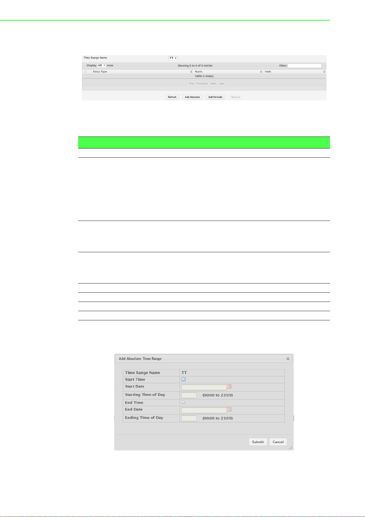
To access this page, click System > Advanced Configuration > Time Ranges >
Entry Configuration.
Figure 4.70 System > Advanced Configuration > Time Ranges > Entry
Configuration
The following table describes the items in the previous figure.
Item Description
Time Range Name Click the drop-down menu to select a time range.
Entry Type The type of time range entry, which is one of the following:
Absolute: Occurs once or has an undefined start or end period.
The duration of an Absolute entry can be hours, days, or even
years. Each time entry configuration can have only one Absolu te
entry.
Periodic: Recurring entry that takes place at fixed intervals. This
type of entry occurs at the same time on one or more days of the
week.
Starts For an Absolute entry, indicates the time, day, month, and year that
the entry begins. If this field is blank, the Absolute entry became
active when it was configured. For a Periodic entry, indicates the time
and day(s) of the week that the entry begins.
Ends For an Absolute entry, indicates the time, day, month, and year that
the entry ends. If this field is blank, the Absolute entry does not have a
defined end. For a Periodic entry, indicates the time and day(s) of the
week that the entry ends.
Refresh Click Refresh to update the screen.
Add Absolute Click Add Absolute to add a new absolute time range.
Add Periodic Click Add Periodic to add a new periodic time range.
Remove Click Remove to remove the selected entries.
To add a new absolute time range:
Click System > Advanced Configuration > Time Ranges > Entry Configuration >
Add Absolute.
Figure 4.71 System > Advanced Configuration > Time Ranges > Entry
Configuration > Add Absolute
EKI-9500 Series User Manual 78
Page 98

The following table describes the items in the previous figure.
Item Description
Time Range Name The time range configuration that will include the Absolute time range
entry.
Start Time Select this option to configure values for the Start Date and the Start-
ing Time of Day. If this option is not selected, the entry becomes
active immediately.
Start Date Click the calendar icon to select the day, month, and year when this
entry becomes active. This field can be configured only if the Start
Time option is selected.
Starting Time of Day Specify the time of day that the entry becomes active by entering the
information in the field or by using the scroll bar in the Choose Ti me
window. Click Now to use the current time of day. Click Done to close
the Choose Time window. This field can be configured only if the St art
Time option is selected.
End Time Select this option to configure values for the End Date and the Ending
Time of Day. If this option is not selected, the entry does not have an
end time; after the configured Start Time begins, the entry will remain
active indefinitely.
End Date Click the calendar icon to select the day, month, and year when this
entry should no longer be active. This field can be configured only if
the End Time option is selected.
Ending Time of Day Specify the time of day that the entry becomes ina ctive by entering the
information in the field or by using the scroll bar in the Choose Ti me
window. Click Now to use the curr ent time of day. Click Done to close
the Choose Time window. This field can be configured only if the End
Time option is selected.
Submit Click Submit to save the values.
Cancel Click Cancel to close the window.
To add a new periodic time range:
Click System > Advanced Configuration > Time Ranges > Entry Configuration >
Add Periodic.
Figure 4.72 System > Advanced Configuration > Time Ranges > Entry
Configuration > Add Periodic
79 EKI-9500 Series User Manual
Page 99

The following table describes the items in the previous figure.
Item Description
Time Range Name The time range configuration that will include the Periodic time range
entry.
Applicable Days Select the days on which the Periodic time range entry is active:
Daily: Every day of the week
Weekdays: Monday through Friday
Weekend: Saturday and Sunday
Days of Week: User-defined start days
Star t Days Indicates on which days the time entry becomes active. If the selected
option in the Applicable Days field is Days of Week, select one or
more days on which the entry becomes active. To select multiple
days, hold the CTRL key and select each desired start day.
Starting Time of Day Specify the time of day that the entry becomes active by entering the
information in the field or by using the scroll bar in the Choose Time
window. Click Now to use the current time of day. Click Done to close
the Choose Time window.
End Days Indicates on which days the time entry ends. If the selected option in
the Applicable Days field is Days of Week, select one or more days on
which the entry ends. To select multiple days, hold the CTRL key and
select each desired end day.
Ending Time of Day Specify the time of day that th e entry becomes inactive by entering the
information in the field or by using the scroll bar in the Choose Time
window. Click Now to use the current time of day. Click Done to close
the Choose Time window.
Submit Click Submit to save the values.
Cancel Click Cancel to close the window.
4.3.2.11 Time Zone Summary
The Time Zone Summary page displays information about the current system time,
the time zone, and the daylight saving time (also known as summer time) settings
configured on the device.
To access this page, click System > Advanced Configuration > Time Zone > Sum-
mary.
Figure 4.73 System > Advanced Configuration > Time Zone > Summary
EKI-9500 Series User Manual 80
Page 100

The following table describes the items in the previous figure.
Item Description
Current Time
Time The current time on the system clock. This time is used to provide
time stamps on log messages. Additionally, some CLI show com-
mands include the time in the command output.
Zone The acronym that represents the time zone.
Date The current date on the system.
Time Source The time source from which the time update is taken:
SNTP: The time has been acquired from an SNTP server.
No Time Source: The time has either been manually configured
or not configured at all.
Time Zone
Zone The acronym that represents the time zone.
Offset The number of hours offset from Coordinated Universal Time (UTC),
which is also known as Greenwich Mean Time (GMT).
Summer Time
Summer Time The summer time mode on the system:
Disable: Summer time is not active, and the time does not shift
based on the time of year.
Recurring: Summer time occurs at the same time every year.
The start and end times and dates for the time shift must be
manually configured.
EU: The system clock uses the standard recurring summer time
settings used in countries in the European Union. When this
field is selected, the rest of the applicable fields on the page
except Offset and Zone are automatically populated and cannot
be edited.
USA: The system clock uses the standard recurring daylight
saving time settings used in the United S t ates. When this field is
selected, the rest of the applicable fields on the page except Offset and Zone are automatically populated and cannot be edited.
Non-Recurring: Summer time settings are in ef fect only between
the start date and end date of the specified year. When this
mode is selected, the summer time settings do not repeat o n a n
annual basis.
Zone The acronym that represents the time zone of the summer time.
Offset The number of hours offset from Coordinated Universal Time (UTC),
which is also known as Greenwich Mean Time (GMT).
Status Indicates if summer time is currently active.
Refresh Click Refresh to update the screen.
Time Zone
Use the Time Zone Configuration page to manually configure the system clock settings. The SNTP client must be disabled to allow manual configuration of the system
time and date.
81 EKI-9500 Series User Manual
 Loading...