


User Manual
EKI-6333AC-M12 Series
EN50155 Industrial M12 Wi-Fi AP

Copyright
Part No. Edition 1
Printed in Taiwan December 2019
The documentation and the software included with this product are copyrighted 2018
by Advantech Co., Ltd. All rights are reserved. Advantech Co., Ltd. reserves the right
to make improvements in the products described in this manual at any time without
notice. No part of this manual may be reproduced, copied, translated or transmitted
in any form or by any means without the prior written permission of Advantech Co.,
Ltd. Information provided in this manual is intended to be accurate and reliable.
However, Advantech Co., Ltd. assumes no responsibility for its use, nor for any
infringements of the rights of third parties, which may result from its use.
Acknowledgments
Intel and Pentium are trademarks of Intel Corporation.
Microsoft Windows and MS-DOS are registered trademarks of Microsoft Corp.
All other product names or trademarks are properties of their respective owners.
Product Warranty (5 years)
Advantech warrants to you, the original purchaser, that each of its products will be
free from defects in materials and workmanship for five years from the date of
purchase.
This warranty does not apply to any products which have been repaired or altered by
persons other than repair personnel authorized by Advantech, or which have been
subject to misuse, abuse, accident or improper installation. Advantech assumes no
liability under the terms of this warranty as a consequence of such events.
Because of Advantech’s high quality-control standards and rigorous testing, most of
our customers never need to use our repair service. If an Advantech product is
defective, it will be repaired or replaced at no charge during the warranty period. For
out of-warranty repairs, you will be billed according to the cost of replacement
materials, service time and freight. Please consult your dealer for more details.
If you think you have a defective product, follow these steps:
1. Collect all the information about the problem encountered. (For example, CPU
speed, Advantech products used, other hardware and software used, etc.) Note
anything abnormal and list any on-screen messages you get when the problem
occurs.
2. Call your dealer and describe the problem. Please have your manual, product,
and any helpful information readily available.
3. If your product is diagnosed as defective, obtain an RMA (return merchandise
authorization) number from your dealer. This allows us to process your return
more quickly.
4. Carefully pack the defective product, a fully-completed Repair and Replacement
Order Card and a photocopy proof of purchase date (such as your sales receipt)
in a shippable container. A product returned without proof of the purchase date
is not eligible for warranty service.
5. Write the RMA number visibly on the outside of the package and ship it pre paid
to your dealer.
ii EKI-6333AC-M12 Series User Manual

Declaration of Conformity
CE
This product has passed the CE test for environmental specifications. Test conditions
for passing included the equipment being operated within an industrial enclosure. In
order to protect the product from being damaged by ESD (Electrostatic Discharge)
and EMI leakage, we strongly recommend the use of CE-compliant industrial
enclosure products.
FCC Class B
This equipment has been tested and found to comply with the limits for a Class B
digital device, pursuant to Part 15 of the FCC Rules. These limits are designed to
provide reasonable protection against harmful interference in a residential
installation. This equipment generates, uses and can radiate radio frequency energy
and, if not installed and used in accordance with the instructions, may cause harmful
interference to radio communications. However, there is no guarantee that
interference will not occur in a particular installation. If this equipment does cause
harmful interference to radio or television reception, which can be determined by
turning the equipment off and on, the user is encouraged to try to correct the
interference by one of the following measures:
Reorient or relocate the receiving antenna.
Increase the separation between the equipment and receiver.
Connect the equipment into an outlet on a circuit different from that to which the
receiver is connected.
Consult the dealer or an experienced radio/TV technician for help.
FCC Caution: Any changes or modifications not expressly approved by the party
responsible for compliance could void the user's authority to operate this equipment.
This device complies with Part 15 of the FCC Rules. Operation is subject to the
following two conditions: (1) This device may not cause harmful interference, and (2)
this device must accept any interference received, including interference that may
cause undesired operation.
FCC RF Radiation Exposure Statement:
1. This Transmitter must not be co-located or operating in conjunction with any
other antenna or transmitter.
2. This equipment complies with FCC RF radiation exposure limits set forth for an
uncontrolled environment. This equipment should be installed and operated with
a minimum distance of 20 centimeters (7.87 inches) between the radiator and
your body.
EKI-6333AC-M12 Series User Manual iii

Technical Support and Assistance
1. Visit the Advantech web site at www.advantech.com/support where you can find
the latest information about the product.
2. Contact your distributor, sales representative, or Advantech's customer service
center for technical support if you need additional assistance. Please have the
following information ready before you call:
– Product name and serial number
– Description of your peripheral attachments
– Description of your software (operating system, version, application software,
etc.)
– A complete description of the problem
– The exact wording of any error messages
Warnings, Cautions and Notes
Warning! Warnings indicate conditions, which if not observed, can cause personal
injury!
Caution! Cautions are included to help you avoid damaging hardware or losing
data. e.g.
There is a danger of a new battery exploding if it is incorrectly installed.
Do not attempt to recharge, force open, or heat the battery. Replace the
battery only with the same or equivalent type recommended by the
manufacturer. Discard used batteries according to the manufacturer's
instructions.
Note! Notes provide optional additional information.
Document Feedback
To assist us in making improvements to this manual, we would welcome comments
and constructive criticism. Please send all such - in writing to:
support@advantech.com
iv EKI-6333AC-M12 Series User Manual

Packing List
Before setting up the system, check that the items listed below are included and in
good condition. If any item does not accord with the table, ple ase co ntact your dealer
immediately.
1 x WiFi AP
4 x Antennas
Safety Instructions
Read these safety instructions carefully.
Keep this User Manual for later reference.
This device is for indoor use only.
Disconnect this equipment from any DC outlet before cleaning. Use a damp
cloth. Do not use liquid or spray detergents for cleaning.
For plug-in equipment, the power outlet socket must be located near the
equipment and must be easily accessible.
Keep this equipment away from humidity.
Put this equipment on a reliable surface during installation. Dropping it or lett ing
it fall may cause damage.
The openings on the enclosure are for air convection. Protect the equipment
from overheating. DO NOT COVER THE OPENINGS.
Make sure the voltage of the power source is correct before connecting the
equipment to the power outlet.
Position the power cord so that people cannot step on it. Do not place anything
over the power cord.
All cautions and warnings on the equipment should be noted.
If the equipment is not used for a long time, disconnect it from the power source
to avoid damage by transient overvoltage.
Never pour any liquid into an opening. This may cause fire or electrical shock.
Never open the equipment. For safety reasons, the equipment should be
opened only by qualified service personnel.
If one of the following situations arises, get the equipment checked by service
personnel:
– The power cord or plug is damaged.
– Liquid has penetrated into the equipment.
– The equipment has been exposed to moisture.
– The equipment does not work well, or you cannot get it to work according to
the user's manual.
– The equipment has been dropped and damaged.
– The equipment has obvious signs of breakage.
DO NOT LEAVE THIS EQUIPMENT IN AN ENVIRONMENT WHERE THE
STORAGE TEMPERATURE MAY GO -40°C (-40°F) ~ 80°C (176°F). THIS
COULD DAMAGE THE EQUIPMENT. THE EQUIPMENT SHOULD BE IN A
CONTROLLED ENVIRONMENT.
The sound pressure level at the operator's position according to IEC 704-1:1982
is no more than 70 dB (A).
DISCLAIMER: This set of instructions is given according to IEC 704-1.
Advantech disclaims all responsibility for the accuracy of any statements
contained herein.
EKI-6333AC-M12 Series User Manual v

Safety Precaution - Static Electricity
Static electricity can cause bodily harm or damage electronic devices. To avoid
damage, keep static-sensitive devices in the static-protective packaging until the
installation period. The following guidelines are also recommended:
Wear a grounded wrist or ankle strap and use gloves to prevent direct contact to
the device before servicing the device. Avoid nylon gloves or work clothes,
which tend to build up a charge.
Always disconnect the power from the device before servicing it.
Before plugging a cable into any port, discharge the voltage stored on the cable
by touching the electrical contacts to the ground surface.
About the Device
This device is for indoor use only.
vi EKI-6333AC-M12 Series User Manual

Contents
Chapter 1 Introduction.........................................1
1.1 Overview................................................................................................... 2
1.2 Device Features............................. ... .... ... ... ... ... .... ... ... ... .... ... ... ................. 2
1.3 Specifications............................................................................................ 2
1.4 Dimensions............................................................................................... 3
Chapter 2 Getting Started....................................4
2.1 Hardware .................................................................................................. 5
2.1.1 Front View..................................................................................... 5
2.1.2 Top View....................................................................................... 5
2.1.3 Bottom View.................................................................................. 6
2.1.4 LED Indicators.............................................................................. 6
2.2 Connecting Hardware............................................................................... 7
2.2.1 Wall Mounting............................................................................... 7
2.2.2 Wireless Connection..................................................................... 8
2.2.3 Network Connection ..................................................................... 9
2.2.4 USB Connection........................................................................... 9
2.2.5 Console Connection ................................................................... 10
2.2.6 Power Connection ............................................. .... ... ... ... ... .... ... .. 10
Chapter 3 Web Interface ....................................15
3.1 Log In...................................................................................................... 16
3.1.1 Changing Default Password....................................................... 17
3.2 Overview................................................................................................. 18
3.3 Network Settings..................................................................................... 19
3.3.1 LAN............................................................................................. 19
3.4 Wireless Settings.................................................................................... 20
3.4.1 Operation Mode.......................................................................... 20
3.4.2 WLAN ......................................................................................... 20
3.5 Administration......................................................................................... 25
3.5.1 Syslog......................................................................................... 25
3.5.2 NTP / Time............................................................................. ..... 25
3.5.3 HTTP .......................................................................................... 26
3.5.4 Configuration Manager............................................................... 27
3.5.5 Upgrade Manager....................................................................... 27
3.5.6 Reset System ....................................... .... ... ... ... .... ..................... 28
3.5.7 Apply Configuration .................................................................... 28
3.5.8 Tools........................................................................................... 29
EKI-6333AC-A Series User Manual vii

List of Figures
Figure 1.1 Dimensions....................................................................................................................3
Figure 2.1 Front View .....................................................................................................................5
Figure 2.2 Top View........................................................................................................................5
Figure 2.3 Bottom View .................................................................................................................. 6
Figure 2.4 System LED Panel ........................................................................................................ 6
Figure 2.5 Wall Mount Installation .................................................................................................. 7
Figure 2.6 Installing the Antenna.................................................................................................... 8
Figure 2.7 Positioning the Antenna................................................................................................. 8
Figure 2.8 M12 X-Coded Connector Pin Assignment.......... .... ...................................... .... ... ... ... ... . 9
Figure 2.9 M12 A-Coded Connector Pin Assignment.......... .... ...................................... .... ... ... ... ... . 9
Figure 2.10 M12 A-Coded Connector Pin Assignment...................................................................10
Figure 2.11 Power Wiring for EKI-6333AC-M12 Series..................................................................11
Figure 2.12 Grounding Connection.................................................................................................12
Figure 2.13 Installing the Power Cable...........................................................................................13
Figure 2.14 Removing the Power Cable......................................................................................... 13
Figure 2.15 Standard M12 5-Pin Female DC Power Input Connector............................................ 14
Figure 3.1 Login Screen ............................................................................................................... 16
Figure 3.2 Administration > HTTP ................................................................................................17
Figure 3.3 Overview......................................................................................................................18
Figure 3.4 Network Settings > LAN ..............................................................................................19
Figure 3.5 Wireless Settings > Operation Mode...........................................................................20
Figure 3.6 Wireless Settings > WLAN > Basic ............................................................................. 20
Figure 3.7 Wireless Settings > WLAN > Advanced ...................................................................... 21
Figure 3.8 Wireless Settings > WLAN > Security ......................................................................... 22
Figure 3.9 Wireless Settings > WLAN > Statistics........................................................................ 22
Figure 3.10 Wireless Settings > WLAN > Access Control.............................................................. 23
Figure 3.11 Wireless Settings > WLAN > Log ................................................................................ 24
Figure 3.12 Administration > Syslog...............................................................................................25
Figure 3.13 Administration > NTP / Time........................................................................................ 25
Figure 3.14 Administration > HTTP ................................................................................................26
Figure 3.15 Administration > Configuration Manager.....................................................................27
Figure 3.16 Administration > Upgrade Manager.............................................................................27
Figure 3.17 Administration > Reset System.................................................................................. 28
Figure 3.18 Administration > Apply Configuration ..........................................................................28
Figure 3.19 Administration > Tools.................................................................................................29
viii EKI-6333AC-A Series User Manual

Chapter 1
1Introduction

1.1 Overview
EKI-6333AC-M12 Series Industrial Wi-Fi AP is designed for railway applications,
including rolling stock. EKI-6333AC-M12 Series support AP/Bridge/Client mode and
is designed with dual 2.4GHz/5GHz wireless module, support IEEE 802.11 a/b/g/n/ac
concurrent dual band with M12 connector to provide a reliable wireless connectivity
for Industrial environments.
EKI-6333AC-M12 Series product has high performance of wireless connectivity for
devices in remote locations where cable connections are impractical. EKI-6333ACM12 Series provides ample bandwidth, even for video application.
1.2 Device Features
Support 802.11ac MIMO 2T2R
WLAN transmission rate up to 867 Mbps
Supports secure access with WEP, 802.1x, WPA/WPA2-Personal, WPA/WPA2-
Enterprise
Provides Web-based configuration
Support Dual band 2.4G/5G concurrent
Design with Dual radio module
Anti-vibration M12 design
Wide Range Power Input 24/48/72/96/110 V
DC
)
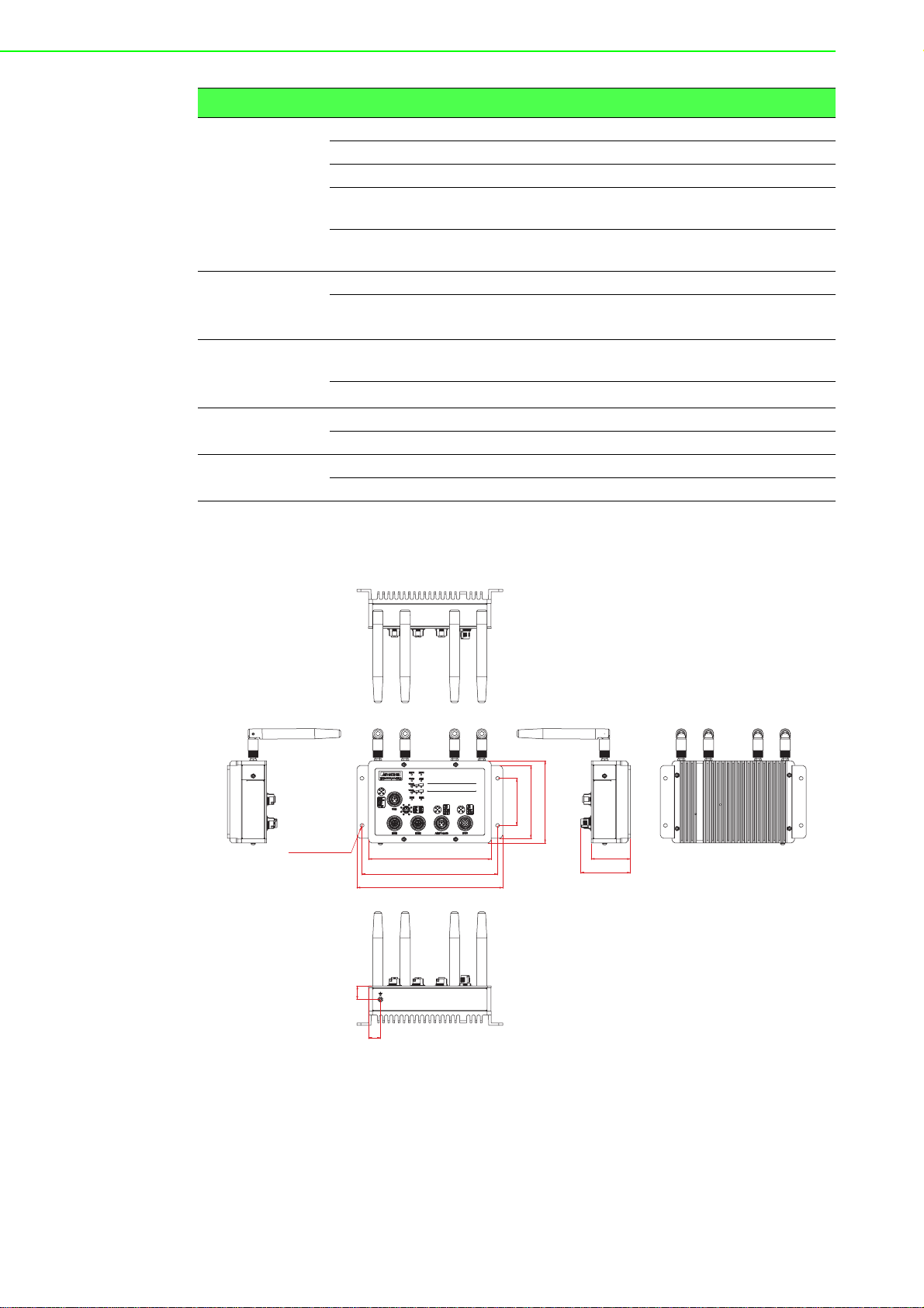
1.3 Specifications
Specifications Description
Interface I/O Port
Console Port M12 A-Code female
USB Port M12 A-Code female
Power Connector M12 A-Code male
Physical Enclosure Metal shell with solid mounting kits
Mounting Wall
Dimensions
(W x H x D)
Weight 0.5 Kg (1.1 lbs)
LED Display System LED Power 1, Power 2, Status, Alarm
Port LED
Environment Operating
Temperature
Storage
Temperature
Ambient Relative
Humidity
M12 X-Code (EKI-6333ACX)
M12 D-Code (EKI-6333ACD)
186 x 50.1 x 104.8 mm (7.32" x 1.97" x 4.13")
WLAN: Quality
LAN: Link/Active
-40°C ~ 75°C (-40°F ~ 166°F)
-40°C ~ 80°C (-40°F ~ 176°F)
10 ~ 95% RH
2 EKI-6333 AC-M12 Series User Manual
Specifications Description
WLAN 2 WLAN 2 WLAN 1 WLAN 1
156.40 [6.16]
50.10 [1.97]
63.40 [2.50]
Ø5 [0.20] hole-4pcs
173 [6.81]
186 [7.32]
15.20 [0.60]
60 [2.36]
17.10
[0.67]
92.80 [3.65]
104.80 [4.13]
Wireless LAN
Communications
Compatibility IEEE 802.11a/b/g/n/ac
Speed Up to 867 Mbps
Antenna 4 (supports 2T2R)
Free Space
Range
Wireless Security Open System, Shared Key, Legacy 8021X, WPA/
Ethernet
Communications
Compatibility IEEE 802.11a/b/g/n/ac
Speed
Power Power
Consumption
Power Input 24/48V
Software Operation Modes Access Point/Bridge/Client mode
Management Web UI
Regulatory
Approvals
EMC CE, FCC Part 15 Subpart B (Class B)
Rail Traffic EN 50155
1.4 Dimensions
Open space 100 m
WPA2, WPA-PSK (TKIP), WPA2-PSK (AES)
100/1000 Mbps EKI-6333ACX)
10/100 Mbps (EKI-6333ACD)
LV Model: 12W
HV Model: 18W
(LV model), 72/96/110VDC (HV model)
DC
Figure 1.1 Dimensions
EKI-6333AC-M12 Series User Manual 3

Chapter 2
2Getting Started

2.1 Hardware
4
6
5
1
2
3
12
2.1.1 Front View
EKI-6333AC-M12
USB
WLAN1
WLAN2
PWR1
Status
ETH1
PWR2
ALM
ETH2
No. Item Description
1 System LED panel See “LED Indicators” on page 6 for further details.
2 USB port M12 5-pin (female) port to connect the USB device.
3 ETH ports ETH ports x 2.
4 Wall mounting holes Screw holes (x4) used in the installation of a wall mounting plate
5 Power input port M12 5-pin (male) DC power connector port.
6 ALM/Console port M12 5-pin (female) port to access the managed switch's
2.1.2 Top View
ETH1 ETH2
ALM/Console
Figure 2.1 Front View
software.
WLAN 2 WLAN 2 WLAN 1 WLAN 1
PWR
Figure 2.2 Top View
No. Item Description
1 Antenna connectors Connectors for WLAN2 antennas.
2 Antenna connectors Connectors for WLAN1 antennas.
EKI-6333AC-M12 Series User Manual 5
2.1.3 Bottom View
1
1
2
3
4
PWR1 PWR2
Status
ETH1
ALM
WLAN1
WLAN2
ETH2
5
6
7
No. Item Description
1 Ground terminal Screw terminal used to ground chassis
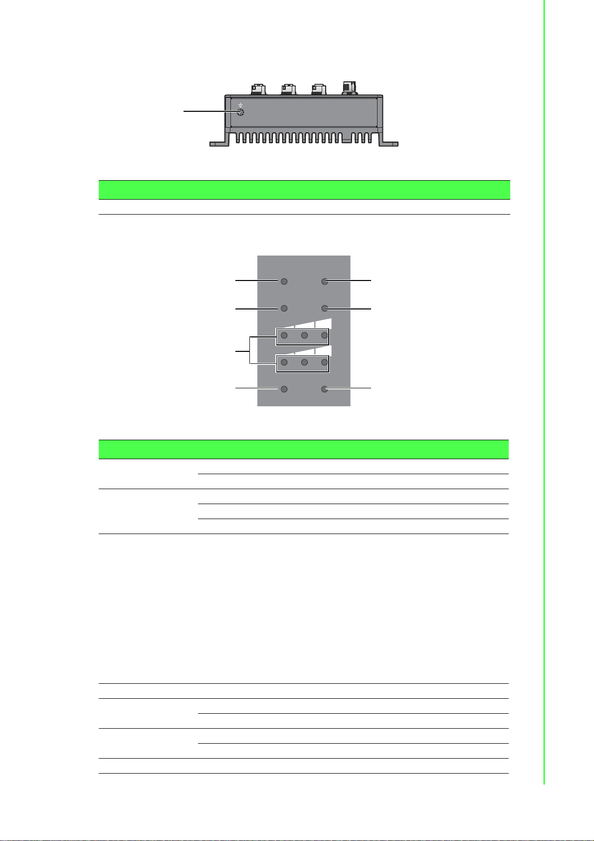
2.1.4 LED Indicators
Figure 2.3 Bottom View
Figure 2.4 System LED Panel
No. LED Name LED Color Description
1 PWR1 Green Power 1 is on
Off Power 1 is off or power error condition exists
2 Status Green System is ready
Green, blinking System is booting
Off System is not functioning
3 Wireless Signal
Strength
Green AP mode:
Enable: LED1 on; LED2, LED3 off
Disable: LED1, LED2, LED3 off
Client mode:
LED1 on: Connect AP successfully
– RSSI > -50dB: LED2, LED3 on
– -50dB > RSSI > -60dB: LED2 on, LED3
blinking
– -60dB > RSSI > -80dB: LED2 on, LED3
off
– -80dB > RSSI: LED2 blinking, LED3 off
4 ETH1 Green, blinking Ethernet port 1 is transmitting or receiving data
5 PWR2 Green Power 2 is on
6 ALM Red Either Power 1 or Power 2 is off
7 ETH2 Green, blinking Ethernet port 2 is transmitting or receiving data
Off Power 2 is off or power error condition exists
Off Power 1, Power 2 are on
6 EKI-6333 AC-M12 Series User Manual

2.2 Connecting Hardware
Po
wer
ALM/Con
sole
E
T
H2
P
W
R
E
T
H1
US
B
ETH1
ETH2
ALM
PW
R1
PW
R2
Status
W
L
AN1
W
LAN1
W
LAN1
W
LAN2
W
LAN
W
L
AN2
EKI-6333AC-M12
2.2.1 Wall Mounting
The wall mounting option provides better shock and vibration resistance than the DIN
rail vertical mount.
Note! When installing, make sure to allow for enough space to properly install
the cabling.
Before the device can be mounted on a wall, you will need to remove the DIN rail
plate.
1. On the installation site, place the device firmly against the wall. Make sure the
device is vertically and horizontally level.
2. Insert a pencil or pen through the screw holes on the mounting bracket to mark
the location of the screw holes on the wall.
3. Remove the device from the wall and drill holes over each marked location (4)
on the wall, keeping in mind that the holes must accommodate wall sinks in
addition to the screws.
4. Insert the wall sinks into the walls.
5. Align the mounting bracket over the screw holes on the wall.
6. Starting with the upper bracket, insert a screw through the bracket and rotate it
to secure. Do not tighten at this point. Repeat for the remaining locations, see
the following figure.
Figure 2.5 Wall Mount Installation
7. Once the device is installed on the wall, tighten the screws to secure the device.
EKI-6333AC-M12 Series User Manual 7

2.2.2 Wireless Connection
R1
12
H
1
1
1. Connect the antenna by screwing the antenna connectors in a clockwise
direction.
W
EKI-6333AC-M12
US
B
E
T
H1
LAN
W
LAN2
W
ALM/Con
LAN1
W
LAN1
sole
P
W
R
PW
R1
PW
R2
Status
ALM
W
L
AN1
W
LAN2
ETH1
ETH2
E
T
H2
Po
w
er
Figure 2.6 Installing the Antenna
2. Position the antenna for optimal signal strength.
Note! The location and position of the antenna is crucial for effective wireless
connectivity
W
LAN2
EKI-6333AC-M12
PW
R1
PW
R2
Status
ALM
W
L
AN1
W
L
AN2
ETH
1
US
ETH2
B
W
LAN1
E
T
H1
E
T
H2
ALM/C
on
sole
P
W
R
Po
wer
Figure 2.7 Positioning the Antenna
8 EKI-6333 AC-M12 Series User Manual

2.2.3 Network Connection
1
2
8
7
6
5
4
3
The managed Ethernet models have Gigabit Ethernet ports (8-pin shielded M12
connector with X coding) circular connectors. The 10/100/1000Mbps ports located on
the switch's front side are used to connect to Ethernet-enabled devices.
2.2.3.1 M12 X-Coded Connector Pin Assignment
Figure 2.8 M12 X-Coded Connector Pin Assignment
Pin Description
1DA+
2DA3DB+
4DB5 DD+
6 DD7 DC8 DC+
2.2.4 USB Connection
The managed USB models have Fast USB ports (5-pin shielded M12 connector with
A coding) circular connectors. The USB port located on the switch's front side are
used to connect to USB-enabled devices.
2.2.4.1 M12 A-Coded Connector Pin Assignment
1
5
4
Figure 2.9 M12 A-Coded Connector Pin Assignment
Pin Description
1DN
2 VBUS
3NC
4DP
5GND
2
3
EKI-6333AC-M12 Series User Manual 9

2.2.5 Console Connection
2
1
3
5
4
The console port, used to access the managed switch’s software, has an 5-pin M12
(male) port. A console cable with the mating M12 (female) port and both a DB-9 and /
or a USB connector is available for purchase from Advantech.
2.2.5.1 M12 A-Coded Connector Pin Assignment
Figure 2.10 M12 A-Coded Connector Pin Assignment
Pin Description
1TX
2RX
3P1-N
4GND
5P1-P
2.2.6 Power Connection
2.2.6.1 Overview
Warning! Power down and disconnect the power cord before servicing or wiring
the device.
Caution! Do not disconnect modules or cabling unless the power is first switched
off.
The device only supports the voltage outlined in the type plate. Do not
use any other power components except those specifically designated
for the device.
Caution! Disconnect the power cord before installation or cable wiring.
The devices can be powered by using the same DC source used to power other
devices. A DC voltage range of 24 to 110 V
must be applied between the V1+
DC
terminal and the V1- terminal (PW1), see the following illustrations. The chassis
ground screw terminal should be tied to the panel or chassis ground. A redundant
power configuration is supported through a secondary power supply unit to reduce
network down time as a result of power loss.
10 EKI-6333AC-M12 Series User Manual

EKI-6333AC-M12 Series support 24 to 110 VDC. Dual power inputs are supported
s
Single DC Power Redundant DC Power
and allow you to connect a backup power source.
Figure 2.11 Power Wiring for EKI-6333AC-M12 Series
2.2.6.2 Considerations
Take into consideration the following guidelines before wiring the device:
The Terminal Block (CN1) is suitable for 12-24 AWG (3.31 - 0.205 mm
value 7 lb-in.
The cross sectional area of the earthing conductors shall be at least 3.31 mm
Calculate the maximum possible current for each power and common wire.
Make sure the power draw is within limits of local electrical code regulations.
For best practices, route wiring for power and devices on separate paths.
Do not bundle together wiring with similar electrical characteristics.
Make sure to separate input and output wiring.
Label all wiring and cabling to the various devices for more effective
management and servicing.
P2 P1
One DC Supply
Chassis
GND
(pane)
P2 P1
Dual DC Supplies
Chassi
GND
(pane)
2
). Torque
2
.
Note! Routing communications and power wiring through the same conduit
may cause signal interference. To avoid interference and signal
degradation, route power and communications wires through separate
conduits.
2.2.6.3 Grounding the Device
Caution! Do not disconnect modules or cabling unless the power is first switched
off.
The device only supports the voltage outlined in the type plate. Do not
use any other power components except those specifically designated
for the device.
Caution! Before connecting the device properly ground the device. Lack of a
proper grounding setup may result in a safety risk and could be
hazardous.
Caution! Do not service equipment or cables during periods of lightning activity.
EKI-6333AC-M12 Series User Manual 11

Caution! Do not service any components unless qualified and authorized to do
Drain Wire with Lug
Connection to
Grounding Point
so.
Caution! Do not block air ventilation holes.
Electromagnetic Interference (EMI) affects the transmission performance of a device.
By properly grounding the device to earth ground through a drain wire, you can setup
the best possible noise immunity and emissions.
Figure 2.12 Grounding Connection
By connecting the ground terminal by drain wire to earth ground the device and
chassis can be ground.
Note! Before applying power to the grounded device, it is advisable to use a
volt meter to ensure there is no voltage difference between the power
supply’s negative output terminal and the grounding point on the device.
2.2.6.4 Wiring the Power Inputs
Caution! Do not disconnect modules or cabling unless the power is first switched
off.
The device only supports the voltage outlined in the type plate. Do not
use any other power components except those specifically designated
for the device.
Warning! Power down and disconnect the power cord before servicing or wiring
the device.
12 EKI-6333AC-M12 Series User Manual

To wire the power inputs:
2
1
1
2
Make sure the power cable is not connected to the switch or the power converter
before proceeding.
1. Align the notch on the cable with the protrusion on the connector port. Before
inserting the cable, the cable must be aligned to the connector to prevent
damage to the pins in the port.
2. Insert the cable and gently push it in. If there is any resistance, remove the
cable and re-align it with the connector.
3. Once the cable is fully seated in the port, turn the nut on the cable to secure it to
the connector.
Figure 2.13 Installing the Power Cable
The power input is now connected to the switch. The switch can be powered on.
To remove the power inputs:
Make sure the power is not connected to the device or the power converter before
proceeding.
1. Loosen the screws securing the connector to the power cable receptor.
2. Remove the power cable from the device.
Figure 2.14 Removing the Power Cable
EKI-6333AC-M12 Series User Manual 13

2.2.6.5 Standard M12 5-Pin Female Pin Assignment
2
1
3
5
4
This section describes the proper connection of the 24, 48, 72, 96 and 11 0 V
DC power connector on the switch. The DC input connector is located on the left side
of the front panel. The power terminals are connected as shown in the following
figure. They are electrically floating inside the unit so that either may be grounded by
the user if desired. The chassis is earthened or ground (GND). The mating
connection to the switch is created through a RD24, female connector. Simply align
the keyed female connector to the male connector and twist the threaded to secure.
Figure 2.15 Standard M12 5-Pin Female DC Power Input Connector
Pin Description
1V12V23V2+
4V1+
5GND
DC
to the
14 EKI-6333AC-M12 Series User Manual

Chapter 3
3Web Interface

3.1 Log In
To access the login window, connect the device to the network, see “Network
Connection” on page 9. Once the device is installed and connected, power on the
device see the following procedures to log into your device.
When the device is first installed, the default IP is 192.168.1.1. You will need to make
sure your network environment supports the device setup before connecting it to the
network.
1. Launch your web browser on a computer.
2. In the browser’s address bar type in the device’s default IP address
(192.168.1.1). The login screen displays.
3. Enter the default user name and password (admin/admin) to log into the
management interface. You can change the default password after you have
successfully logged in.
4. Click Login to enter the management interface.
Figure 3.1 Login Screen
Note! Screen may differ depending on Web browsers.
16 EKI-6333AC-M12 Series User Manual

3.1.1 Changing Default Password
The HTTP page allows you to configure the WiFi AP login details.
1. Log in to the user interface menu, see “Basic” on page 20.
2. Navigate to Home > Administration > HTTP. The HTTP configuration page dis-
plays.
3. Enter the username of the profile to change (currently logged in user displays),
then enter the new password under the Password field.
4. Re-type the same password in the Confirm Password field.
5. Click Apply to change the current account settings.
Figure 3.2 Administration > HTTP
EKI-6333AC-M12 Series User Manual 17

3.2 Overview
To access this page, click Overview.
The following table describes the items in the previous figure.
Item Description
System Info
Firmware Version Displays the current firmware version of the device.
Local Hostname Displays the current local hostname of the device.
System Time Displays the current date of the device.
System Up Time Displays the time since the last device reboot.
System Platform Displays the model name of the device.
Local Network
Local IP Address Displays the assigned IP address of the device.
Local Netmask Displays the assigned netmask of the device.
MAC Address Displays the MAC address of the device.
System Status
Memory Utilization Displays the total memory utilization in terms of percentage.
CPU Utilization Displays the total CPU utilization in terms of percentage.
Figure 3.3 Overview
18 EKI-6333AC-M12 Series User Manual

3.3 Network Settings
3.3.1 LAN
To access this page, click Network Settings > LAN.
Figure 3.4 Network Settings > LAN
The following table describes the items in the previous figure.
Item Description
Local Hostname Enter the device name: up to 31 alphanumeric characters.
Network mode Click the drop-down menu to select the IP Address Setting mode:
Static or DHCP client.
IP Address Enter a value to specify the IP address of the interface. The defa ult
is 192.168.1.1.
Subnet Mask Enter a value to specify the IP subnet mask for the interface. The
default is 255.255.255.0.
Default Gateway Enter a value to specify the default gateway for the interface.
Primary DNS Server Enter a value to specify the primary DNS server for the interface.
Secondary DNS Server Enter a value to specify the secondary DNS server for the
interface.
MAC Address Display the MAC address to which packets are statically
forwarded.
DHCP Server Select Enabled or Disabled to designate the DHCP server
function type. When a new DHCP server mode is selected, the
switch requires a system restart for the new mode to take effect.
Start IP Address Enter starting a IP address for the IP assignment.
Pool Counter Enter a variable to define the number of IP addresses for a given
network.
Leasetime Enter in the value designating the lease time for the DHCP server.
Submit Click Submit to save the values and update the screen.
Note! All new configurations will take effect after rebooting. To reboot the
device, click Administration > Tools > Reboot.
EKI-6333AC-M12 Series User Manual 19
3.4 Wireless Settings
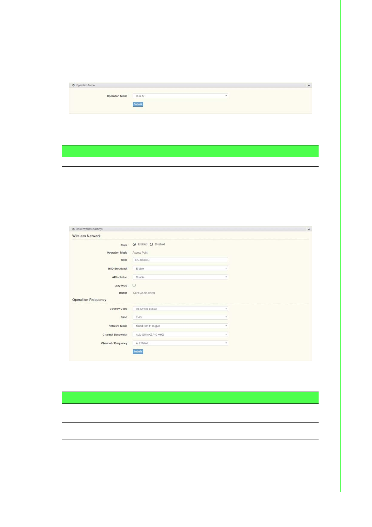
3.4.1 Operation Mode
To access this page, click Wireless Settings > Operation Mode
Figure 3.5 Wireless Settings > Operation Mode
The following table describes the items in the previous figure.
Item Description
Operation Mode Click the drop-down menu to select an operation mode.
Submit Click Submit to save the values and update the screen.
3.4.2 WLAN
3.4.2.1 Basic
To access this page, click Wireless Settings > WLAN > Basic.
Figure 3.6 Wireless Settings > WLAN > Basic
The following table describes the items in the previous figure.
Item Description
Wireless Network
State Select Enabled or Disabled to set the WLAN state.
Operation Mode Supports three modes, Operation Mode (default), Bridge and
Client mode.
SSID Enter the name to distinguish it from other networks in your
neighborhood.
SSID Broadcast Click the drop-down menu to enable or disab le the SSID broadcast
function.
AP Isolation Click the drop-down menu to enable or disable the AP Isolation
function.
20 EKI-6333AC-M12 Series User Manual

Item Description
Lazy WDS Click the checkbox to enable the lazy WDS function.
BSSID Display the MAC address of the device.
Operation Frequency
Country Code Click the drop-down menu to select the country code to specify
Band Click the drop-down menu to select the band channel.
Network Mode Click the drop-down menu to select the network mode.
Channel Bandwidth Click the drop-down menu to select the band and channel
Channel / Frequency Select the 2.4 or 5G wireless frequency to the least congested
Submit Click Submit to save the values and update the screen.
3.4.2.2 Advanced
To access this page, click Wireless Settings > WLAN > Advanced.
different selectable channels. Some specific channels and/or
operational frequency bands are country dependent.
bandwidth.
channel. The available settings on a 2.4G setting ar e 2.412 GHz to
2.484 GHz. For 5G, the available settings are 5.18 GHz to 5.825
GHz. The function is only enabled when Operation Mode is set to
Access Point.
Figure 3.7 Wireless Settings > WLAN > Advanced
The following table describes the items in the previous figure.
Item Description
Access Point Settings
Beacon Interval Enter a value (20-999) to specify the frequency interval to
broadcast packets.
Data Beacon Rate
(DTIM)
Advanced Wireless Setting
Transmission Power Use the scroll bar to set the transmission power of the WiFi. By
Submit Click Submit to save the values and update the screen.
DTIM, which stands for Delivery Traffic Indication Message, is
contained in the data packets. It is for enhancing the wireless
transmission efficiency. The default is set to 2. Enter a value
between 1 and 255.
default the AP transmits at full power: Full, Half, Quarter.
EKI-6333AC-M12 Series User Manual 21
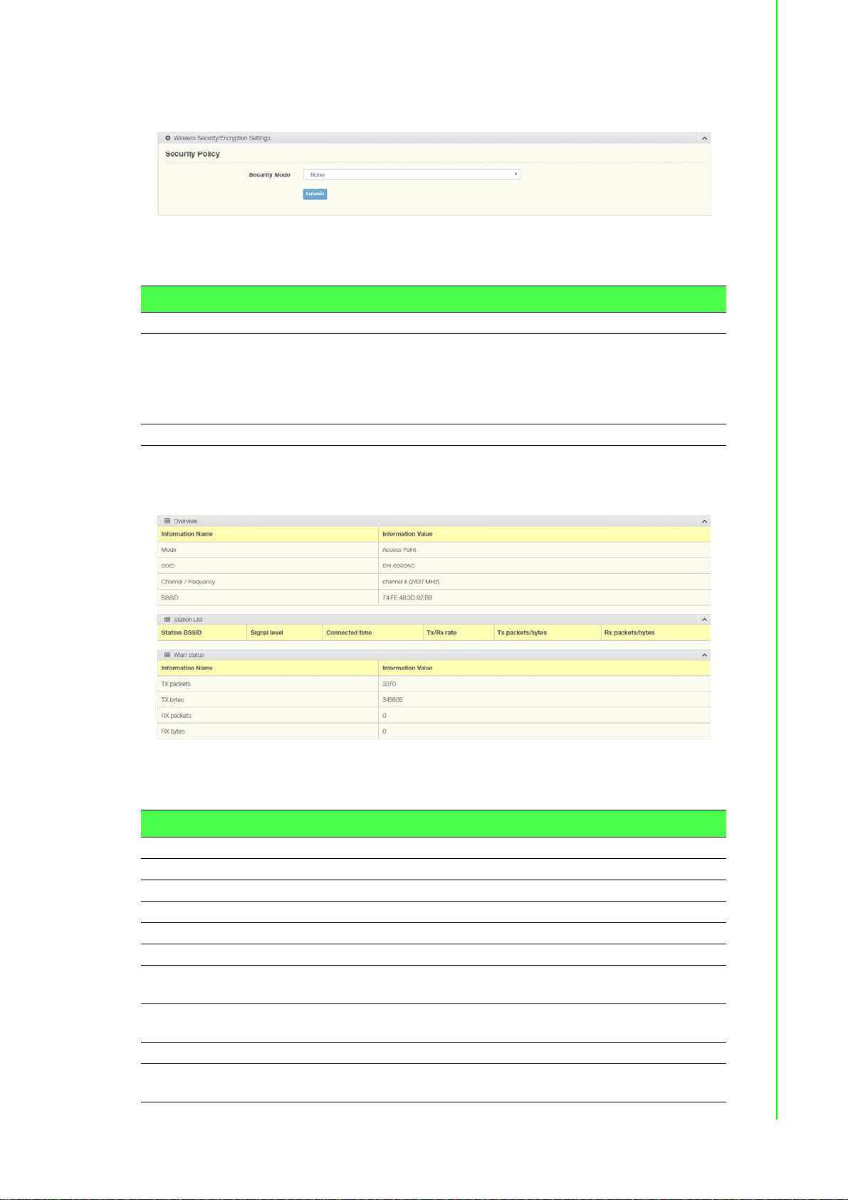
3.4.2.3 Security
To access this page, click Wireless Settings > WLAN > Security.
The following table describes the items in the previous figure.
Item Description
Security Policy
Security Mode Click the drop-down menu to select the encryption when
Submit Click Submit to save the values and update the screen.
3.4.2.4 Statistics
To access this page, click Wireless Settings > WLAN > Statistics.
Figure 3.8 Wireless Settings > WLAN > Security
communication. Available options: None, WEP, WPA-Personal and
WPA/WPA2-Enterprise. If data encryption is enabled, the key is
required and only sharing the same key with other wireless
devices can the communication be established.
Figure 3.9 Wireless Settings > WLAN > Statistics
The following table describes the items in the previous figure.
Item Description
Overview
Mode Display the current operation mode of the device.
SSID Display the SSID.
Channel / Frequency Display the current channel / frequency of the device.
BSSID Display the MAC address of the device.
Station List
Station BSSID Displays the basic service set identifier (BSSID), access point
unique MAC address.
Signal level Displays the power level measure in decibel-milliwatts of the listed
BSSID.
Connected time Displays the total uptime period.
Tx/Rx rate Displays the transmit (Tx) to receive (Rx) rate of the connected
client.
22 EKI-6333AC-M12 Series User Manual

Item Description
Tx packets/bytes Displays the total Tx packets and corresponding bytes.
Rx packets/bytes Displays the total Rx packets and corresponding bytes.
Wlan status
TX packets Display the current Tx packets.
TX bytes Display the current Tx bytes.
RX packets Display the current Rx packets.
RX bytes Display the current Rx bytes.
3.4.2.5 Access Control
The Access Control feature is only available when the wireless mode of the device is
set to AP, see “Basic” on page 20.
Access Control allows for an administrator to allow or deny access by defining
specific devices through their MAC address.
To access this page, click Wireless Settings > WLAN > Access Control.
Figure 3.10 Wireless Settings > WLAN > Access Control
The following table describes the items in the previous figure.
Item Description
Access Control Method Click the drop-down menu to set the access control method:
Disable, Deny or Allow.
In the Deny or Allow menu, enter the MAC address of the target
device - support for up to 32 target devices.
Submit Click Submit to save the values and update the screen.
EKI-6333AC-M12 Series User Manual 23

3.4.2.6 Log
To access this page, click Wireless Settings > WLAN > Log.
The following table describes the items in the previous figure.
Figure 3.11 Wireless Settings > WLAN > Log
Item Description
Download Click Download to download the log file.
Auto Scroll Click the checkbox to enable the Auto Scroll function.
24 EKI-6333AC-M12 Series User Manual

3.5 Administration
3.5.1 Syslog
Users can enable the syslogd function to record historical events or messages locally
or on a remote syslog server.
To access this page, click Administration > Syslog.
The following table describes the items in the previous figure.
Item Description
Download Click Download to download the log file.
Auto Scroll Click the checkbox to enable the Auto Scroll function.
3.5.2 NTP / Time
To access this page, click Administration > NTP / Time.
The following table describes the items in the previous figure.
Figure 3.12 Administration > Syslog
Figure 3.13 Administration > NTP / Time
Item Description
System Time Displays the system date and time.
Manual Time Set the system date and time.
NTP Service Click the drop-down menu to enable the NTP server.
Time Zone Click the drop-down menu to select a system time zone.
EKI-6333AC-M12 Series User Manual 25

Item Description
NTP Server Enter the address of the SNTP server.
Submit Click Submit to save the values and update the screen.
3.5.3 HTTP
To access this page, click Administration > HTTP.
The following table describes the items in the previous figure.
Figure 3.14 Administration > HTTP
Item Description
HTTP common settings
Redirect HTTP requests
to HTTPS
HTTPS port Enter the port to forward HTTPS traffic, default: 443.
HTTP port Enter the port to forward HTTP traffic, default: 80.
Username and password
Username Display the user name.
Password Enter the character set for the define password type.
Confirm Password Retype the password entry to conf ir m the pr ofile password.
Submit Click Submit to save the values and update the screen.
Click the drop-down menu to enable or disable the funct i on . By
default the function is disabled. When enabled, a NAT setting and
Open Ports can be setup to direct connection requests to an
internal server.
26 EKI-6333AC-M12 Series User Manual

3.5.4 Configuration Manager
To access this page, click Administration > Configuration Manager.
Figure 3.15 Administration > Configuration Manager
The following table describes the items in the previous figure.
Item Description
Backup
Download Configuration Click Backup to backup the device settings.
To Click PC or USB Drive to select the correct file location.
Restore
Choose File Click Choose File to select the configuration file.
Upload Archive Click Upload Archive to restore the configuration to the device.
From Click PC or USB Drive to select the correct file location.
USB Drive Backup
Automatically Backup Select Enabled or Disabled to enable the function.
3.5.5 Upgrade Manager
To access this page, click Administration > Upgrade Manager.
Figure 3.16 Administration > Upgrade Manager
The following table describes the items in the previous figure.
Item Description
Upgrade Manager Click Choose File to select the configuration file.
Upload Click Upload to upload to the current version.
EKI-6333AC-M12 Series User Manual 27

3.5.6 Reset System
To access this page, click Administration > Reset System.
Figure 3.17 Administration > Reset System
The following table describes the items in the previous figure.
Item Description
Reset Click Reset to have all configuration parameters reset to their
factory default values. All changes that have been made will be
lost, even if you have issued a save.
3.5.7 Apply Configuration
To access this page, click Administration > Apply Configuration.
Figure 3.18 Administration > Apply Configuration
The following table describes the items in the previous figure.
Item Description
Apply and Reboot Click Apply and Reboot to have configuration changes you have
made to be saved across a system reboot. All changes submitted
since the previous save or system reboot will be retained by the
switch.
28 EKI-6333AC-M12 Series User Manual

3.5.8 Tools
To access this page, click Administration > Tools.
The following table describes the items in the previous figure.
Item Description
Reboot
Reboot Click Reboot to reboot the device. Any configuration changes you
Ping
IP Address / Name Enter the IP address or host name of the station to ping. The initial
Ping Click Ping to display ping result for the IP address.
Figure 3.19 Administration > Tools
have made since the last time you issued a save will be lost.
value is blank. The IP Address or host name you enter is not
retained across a power cycle. Host names are composed of
series of labels concatenated with periods. Each label must be
between 1 and 63 characters long, maximum of 64 characters.
EKI-6333AC-M12 Series User Manual 29

www.advantech.com
Please verify specifications before quoting. This guide is intended for reference
purposes only.
All product specifications are subject to change without notice.
No part of this publication may be reproduced in any form or by any means,
electronic, photocopying, recording or otherwise, without prior written
permission of the publisher.
All brand and product names are trademarks or registered trademarks of their
respective companies.
© Advantech Co., Ltd. 2019
 Loading...