

Page 1

User Manual
EKI-6333AC-2G Series
IEEE 802.11 a/b/g/n/ac WiFi AP
Page 2

Copyright
The documentation and the software included with this product are copyrighted 2018
by Advantech Co., Ltd. All rights are reserved. Advantech Co., Ltd. reserves the right
to make improvements in the products described in this manual at any time without
notice. No part of this manual may be reproduced, copied, translated or transmitted
in any form or by any means without the prior written permission of Advantech Co.,
Ltd. Information provided in this manual is intended to be accurate and reliable.
However, Advantech Co., Ltd. assumes no responsibility for its use, nor for any
infringements of the rights of third parties, which may result from its use.
Acknowledgments
Intel and Pentium are trademarks of Intel Corporation.
Microsoft Windows and MS-DOS are registered trademarks of Microsoft Corp.
All other product names or trademarks are properties of their respective owners.
Product Warranty (5 years)
Advantech warrants to you, the original purchaser, that each of its products will be
free from defects in materials and workmanship for five years from the date of
purchase.
This warranty does not apply to any products which have been repaired or altered by
persons other than repair personnel authorized by Advantech, or which have been
subject to misuse, abuse, accident or improper installation. Advantech assumes no
liability under the terms of this warranty as a consequence of such events.
Because of Advantech’s high quality-control standards and rigorous testing, most of
our customers never need to use our repair service. If an Advantech product is
defective, it will be repaired or replaced at no charge during the warranty period. For
out of-warranty repairs, you will be billed according to the cost of replacement
materials, service time and freight. Please consult your dealer for more details.
If you think you have a defective product, follow these steps:
1. Collect all the information about the problem encountered. (For example, CPU
speed, Advantech products used, other hardware and software used, etc.) Note
anything abnormal and list any on-screen messages you get when the problem
occurs.
2. Call your dealer and describe the problem. Please have your manual, product,
and any helpful information readily available.
3. If your product is diagnosed as defective, obtain an RMA (return merchandise
authorization) number from your dealer. This allows us to process your return
more quickly.
4. Carefully pack the defective product, a fully-completed Repair and Replacement
Order Card and a photocopy proof of purchase date (such as your sales receipt)
in a shippable container. A product returned without proof of the purchase date
is not eligible for warranty service.
5. Write the RMA number visibly on the outside of the package and ship it prepaid
to your dealer.
Part No. Edition 1
Printed in Taiwan April 2020
ii EKI-6333AC-2G Series User Manual
Page 3

Declaration of Conformity
CE
This product has passed the CE test for environmental specifications. Test conditions
for passing included the equipment being operated within an industrial enclosure. In
order to protect the product from being damaged by ESD (Electrostatic Discharge)
and EMI leakage, we strongly recommend the use of CE-compliant industrial
enclosure products.
FCC Class B
This equipment has been tested and found to comply with the limits for a Class B
digital device, pursuant to Part 15 of the FCC Rules. These limits are designed to
provide reasonable protection against harmful interference in a residential
installation. This equipment generates, uses and can radiate radio frequency energy
and, if not installed and used in accordance with the instructions, may cause harmful
interference to radio communications. However, there is no guarantee that
interference will not occur in a particular installation. If this equipment does cause
harmful interference to radio or television reception, which can be determined by
turning the equipment off and on, the user is encouraged to try to correct the
interference by one of the following measures:
Reorient or relocate the receiving antenna.
Increase the separation between the equipment and receiver.
Connect the equipment into an outlet on a circuit different from that to which the
receiver is connected.
Consult the dealer or an experienced radio/TV technician for help.
FCC Caution: Any changes or modifications not expressly approved by the party
responsible for compliance could void the user's authority to operate this equipment.
This device complies with Part 15 of the FCC Rules. Operation is subject to the
following two conditions: (1) This device may not cause harmful interference, and (2)
this device must accept any interference received, including interference that may
cause undesired operation.
FCC RF Radiation Exposure Statement:
1. This Transmitter must not be co-located or operating in conjunction with any
other antenna or transmitter.
2. This equipment complies with FCC RF radiation exposure limits set forth for an
uncontrolled environment. This equipment should be installed and operated with
a minimum distance of 20 centimeters (7.87 inches) between the radiator and
your body.
EKI-6333AC-2G Series User Manual iii
Page 4

Technical Support and Assistance
1. Visit the Advantech web site at www.advantech.com/support where you can find
the latest information about the product.
2. Contact your distributor, sales representative, or Advantech's customer service
center for technical support if you need additional assistance. Please have the
following information ready before you call:
– Product name and serial number
– Description of your peripheral attachments
– Description of your software (operating system, version, application software,
etc.)
– A complete description of the problem
– The exact wording of any error messages
Warnings, Cautions and Notes
Warning! Warnings indicate conditions, which if not observed, can cause personal
injury!
Caution! Cautions are included to help you avoid damaging hardware or losing
data. e.g.
There is a danger of a new battery exploding if it is incorrectly installed.
Do not attempt to recharge, force open, or heat the battery. Replace the
battery only with the same or equivalent type recommended by the
manufacturer. Discard used batteries according to the manufacturer's
instructions.
Note! Notes provide optional additional information.
Document Feedback
To assist us in making improvements to this manual, we would welcome comments
and constructive criticism. Please send all such - in writing to:
support@advantech.com
iv EKI-6333AC-2G Series User Manual
Page 5

Packing List
Before setting up the system, check that the items listed below are included and in
good condition. If any item does not accord with the table, please contact your dealer
immediately.
1 x EKI-6333AC-2G Wi-Fi AP
1 x Power cord and PoE injector
2 x Pole mounting clamp
4 x Antennas
1 x mounting screws
Safety Instructions
Read these safety instructions carefully.
Keep this User Manual for later reference.
This device is for indoor use only.
Disconnect this equipment from any DC outlet before cleaning. Use a damp
cloth. Do not use liquid or spray detergents for cleaning.
For plug-in equipment, the power outlet socket must be located near the
equipment and must be easily accessible.
Keep this equipment away from humidity.
Put this equipment on a reliable surface during installation. Dropping it or letting
it fall may cause damage.
The openings on the enclosure are for air convection. Protect the equipment
from overheating. DO NOT COVER THE OPENINGS.
Make sure the voltage of the power source is correct before connecting the
equipment to the power outlet.
Position the power cord so that people cannot step on it. Do not place anything
over the power cord.
All cautions and warnings on the equipment should be noted.
If the equipment is not used for a long time, disconnect it from the power source
to avoid damage by transient overvoltage.
Never pour any liquid into an opening. This may cause fire or electrical shock.
Never open the equipment. For safety reasons, the equipment should be
opened only by qualified service personnel.
If one of the following situations arises, get the equipment checked by service
personnel:
– The power cord or plug is damaged.
– Liquid has penetrated into the equipment.
– The equipment has been exposed to moisture.
– The equipment does not work well, or you cannot get it to work according to
the user's manual.
– The equipment has been dropped and damaged.
– The equipment has obvious signs of breakage.
DO NOT LEAVE THIS EQUIPMENT IN AN ENVIRONMENT WHERE THE
STORAGE TEMPERATURE MAY GO -40°C (-40°F) ~ 80°C (176°F). THIS
COULD DAMAGE THE EQUIPMENT. THE EQUIPMENT SHOULD BE IN A
CONTROLLED ENVIRONMENT.
The sound pressure level at the operator's position according to IEC 704-1:1982
is no more than 70 dB (A).
EKI-6333AC-2G Series User Manual v
Page 6

DISCLAIMER: This set of instructions is given according to IEC 704-1.
Advantech disclaims all responsibility for the accuracy of any statements
contained herein.
Safety Precaution - Static Electricity
Static electricity can cause bodily harm or damage electronic devices. To avoid
damage, keep static-sensitive devices in the static-protective packaging until the
installation period. The following guidelines are also recommended:
Wear a grounded wrist or ankle strap and use gloves to prevent direct contact to
the device before servicing the device. Avoid nylon gloves or work clothes,
which tend to build up a charge.
Always disconnect the power from the device before servicing it.
Before plugging a cable into any port, discharge the voltage stored on the cable
by touching the electrical contacts to the ground surface.
vi EKI-6333AC-2G Series User Manual
Page 7

Contents
Chapter 1 Introduction ......................................... 1
1.1 Overview ................................................................................................... 2
1.2 Device Features........................................................................................ 2
1.3 Specifications............................................................................................ 2
1.4 Dimensions ............................................................................................... 3
Chapter 2 Getting Started .................................... 4
2.1 Hardware .................................................................................................. 5
2.1.1 Front View..................................................................................... 5
2.1.2 Rear View ..................................................................................... 6
2.1.3 Top View....................................................................................... 6
2.1.4 Bottom View.................................................................................. 7
2.1.5 Right View..................................................................................... 7
2.1.6 Left View ....................................................................................... 8
2.1.7 LED Indicators .............................................................................. 9
2.2 Connecting Hardware ............................................................................. 10
2.2.1 Wall Mounting ............................................................................. 10
2.2.2 Wireless Connection................................................................... 11
2.2.3 Network Connection ................................................................... 12
2.2.4 I/O Port Cover............................................................................. 13
2.2.5 Power Connection ...................................................................... 14
2.3 Reset Button ........................................................................................... 16
Chapter 3 Web Interface .................................... 18
3.1 Log In ...................................................................................................... 19
3.1.1 Password .................................................................................... 20
3.2 Overview ................................................................................................. 20
3.3 Address Resolution Protocol................................................................... 21
3.4 Interface Settings .................................................................................... 22
3.4.1 LAN............................................................................................. 22
3.4.2 WAN ........................................................................................... 23
3.4.3 Wireless 2.4GHz......................................................................... 25
3.4.4 Wireless 5GHz............................................................................ 38
3.5 Network Settings..................................................................................... 39
3.5.1 Static Route ................................................................................ 39
3.5.2 Forwarding.................................................................................. 39
3.5.3 Security....................................................................................... 40
3.6 Management ........................................................................................... 42
3.6.1 Password Manager..................................................................... 42
3.6.2 Syslog ......................................................................................... 42
3.6.3 NTP / Time.................................................................................. 44
3.6.4 SNMP ......................................................................................... 45
3.6.5 Remote Services ........................................................................ 46
3.6.6 Configuration Manager ............................................................... 47
3.6.7 Firmware Upgrade ...................................................................... 47
3.6.8 Reset System ............................................................................. 47
3.6.9 Apply Configuration .................................................................... 48
3.6.10 Reboot Device ............................................................................ 48
3.7 Tools ....................................................................................................... 49
3.7.1 Diagnostics ................................................................................. 49
EKI-6333AC-2G Series User Manual 1
Page 8

List of Figures
Figure 1.1 Dimensions.................................................................................................................... 3
Figure 2.1 Front View ..................................................................................................................... 5
Figure 2.2 Rear View ...................................................................................................................... 6
Figure 2.3 Top View........................................................................................................................ 6
Figure 2.4 Bottom View as Seen Without a Port Cover.................................................................. 7
Figure 2.5 Right View ..................................................................................................................... 7
Figure 2.6 Left View........................................................................................................................ 8
Figure 2.7 System LED Panel ........................................................................................................ 9
Figure 2.8 Mounting Screw Installation......................................................................................... 10
Figure 2.9 Wall Mount Installation ................................................................................................ 11
Figure 2.10 Installing the Top Antennas ......................................................................................... 11
Figure 2.11 Installing the Bottom Antennas.................................................................................... 12
Figure 2.12 Ethernet Plug & Connector Pin Position...................................................................... 12
Figure 2.13 Removing the I/O Cover .............................................................................................. 13
Figure 2.14 Installing the I/O Cover ................................................................................................ 14
Figure 2.15 Connecting Power to the PoE LAN Port...................................................................... 15
Figure 2.16 Grounding Connection................................................................................................. 16
Figure 2.17 Reset Button Location ................................................................................................. 17
Figure 3.1 Login Screen ............................................................................................................... 19
Figure 3.2 Administration > HTTP ................................................................................................ 20
Figure 3.3 Status > Overview, System Info and LAN Interface .................................................... 20
Figure 3.4 Status > Overview, WAN Interface, DHCP Leases, & System Status......................... 21
Figure 3.5 Status > ARP............................................................................................................... 22
Figure 3.6 Interface > LAN .......................................................................................................... 22
Figure 3.7 Interface > WAN > Network Mode............................................................................... 23
Figure 3.8 Interface > WAN > Network Mode > Static.................................................................. 24
Figure 3.9 Interface > WAN > Network Mode............................................................................... 24
Figure 3.10 Interface > WAN > Network Mode > PPPoE ............................................................... 25
Figure 3.11 Wireless - 2.4GHz > Basic > Access Point.................................................................. 26
Figure 3.12 Wireless - 2.4GHz > Basic > Client ............................................................................. 27
Figure 3.13 Wireless - 2.4GHz > Basic > Bridged Repeater .......................................................... 28
Figure 3.14 Wireless - 2.4GHz > Advanced ................................................................................... 30
Figure 3.15 Wireless - 2.4GHz > Advanced ................................................................................... 31
Figure 3.16 Wireless - 2.4GHz > Security ...................................................................................... 32
Figure 3.17 Wireless - 2.4GHz > Security ...................................................................................... 32
Figure 3.18 Wireless - 2.4GHz > Multiple SSID.............................................................................. 33
Figure 3.19 Wireless - 2.4GHz > QoS ............................................................................................ 34
Figure 3.20 Wireless - 2.4GHz > Statistics..................................................................................... 35
Figure 3.21 Wireless - 2.4GHz > Access Control ........................................................................... 36
Figure 3.22 Wireless - 2.4GHz > Site Survey................................................................................. 36
Figure 3.23 Wireless - 2.4GHz > Site Survey................................................................................. 37
Figure 3.24 Wireless - 2.4GHz > Log ............................................................................................. 38
Figure 3.25 Networking > Static Route.......................................................................................... 39
Figure 3.26 Networking > Forwarding > Port Forwarding............................................................ 39
Figure 3.27 Networking > Forwarding > DMZ ............................................................................... 40
Figure 3.28 Networking > Security > Filter .................................................................................... 40
Figure 3.29 Networking > Security > VPN Passthrough................................................................ 41
Figure 3.30 Management > Password Manager........................................................................... 42
Figure 3.31 Management > Syslog................................................................................................ 43
Figure 3.32 Management > NTP / Time......................................................................................... 44
Figure 3.33 Management > SNMP ................................................................................................ 45
Figure 3.34 Management > Remote Services.............................................................................. 46
Figure 3.35 Management > Configuration Manager ..................................................................... 47
Figure 3.36 Management > Firmware Upgrade............................................................................. 47
Figure 3.37 Management > Apply Configuration........................................................................ 47
Figure 3.38 Management > Apply Configuration........................................................................ 48
2 EKI-6333AC-2G Series User Manual
Page 9

Figure 3.39 Management > Reboot Device ................................................................................. 48
Figure 3.40 Tools > Diagnostics .................................................................................................... 49
EKI-6333AC-2G Series User Manual 3
Page 10

Chapter 1
1Introduction
Page 11

1.1 Overview
The EKI-6333AC-2G Series is a feature rich wireless AP which provides a reliable
wireless connectivity for industrial environments. The PoE injector enhances
flexibility in deployment of this AP even where the DC power supply is hard to fulfill.
With the support of STP, WMM and IGMP snooping protocols, EKI-6333AC-2G
effectively improves the reliability of wireless connectivity, especially in applications
that need high reliability and high throughput data transmission. To secure wireless
connections, EKI-6333AC-2G implements the latest encryption technologies
including WPA2/WPA for powerful security authentication.
1.2 Device Features
Support 802.11 a/b/g/n/ac MIMO 2T2R
WLAN transmission rate up to 867 Mbps
Supports secure access with WEP, WPA/WPA2-Personal, WPA/WPA2-
Enterprise
Provides Web-based configuration
Support Dual band 2.4G/5Ghz Concurrent
IP55 waterproof
1.3 Specifications
Specifications Description
Interface I/O Port 2 x RJ45
Power Connector RJ45, Passive 24V PoE
Physical Enclosure Aluminum die-casting
Mounting Wall, pole
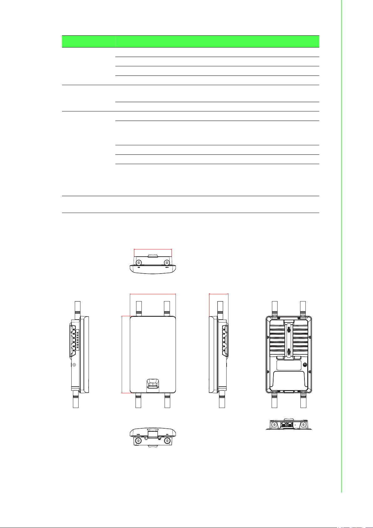
Dimensions
(W x H x D)
Weight 500g
LED Display System LED System: Power
Reboot Trigger Built-in WDT (watchdog timer)
Environment Operating
Temperature
Storage
Temperature
Ambient Relative
Humidity
Wireless LAN
Communications
Compatibility 2.4 GHz: IEEE 802.11 b/g/n
Speed Up to 867 Mbps
Network Mode Infrastructure
Free Space
Range
Antenna 4 x reverse SMA connectors
Wireless Security WEP, WPA/WPA2-Personal, WPA/WPA2-Enterprise
114.3 x 191.7 x 47.7 mm (4.5" x 7.55" x 1.88")
WLAN: Link/Active
LAN: Link/Active
-20 ~ 70 °C (-4~158°F)
-30 ~ 80°C (-22 ~ 176°F)
10 ~ 95% RH
5 GHz: IEEE 802.11 a/n/ac
Open space 100 m
Default external 5 dBi Omni antenna
EKI-6333AC-2G Series User Manual 2
Page 12
Specifications Description
93.96 [3.699]
47.71 [1.878]
191.74 [7.549]
114.33 [4.501]
Ethernet
Communications
Power Power
Software Management Telnet, FTP, SNMP, Web UI, SSH
Regulatory
Approvals
Compatibility IEEE 802.11a/b/g/n/ac
Speed 10/100/1000 Mbps
Port Connector 2 x 8-pin RJ45
Protection Built-in 1.5 KV magnetic isolation
15W
Consumption
Power Input DC 24V / 1A
Wireless Radio on/off, WMM/Regatta Mode, Output Power
Control, Beacon Interval, RTS/ CTS threshold, DTIM
Interval
Operation Modes Access Point, Client, Repeater mode
Configuration Web Browser
Protocol ARP, ICMP, IPv4, IPv6, TCP, UDP, DHCP Client,
DHCP Server, Auto IP, Telnet, DNS, SNMP, HTTP,
DMZ, PPPoE, DHCP server, VPN Passthrough,
Telnet Server, SSH Server, FTP Server, QoS
EMC CE, FCC Part 15 Subpart B (Class B)
1.4 Dimensions
Figure 1.1 Dimensions
3 EKI-6333AC-2G Series User Manual
Page 13

Chapter 2
2Getting Started
Page 14
2.1 Hardware
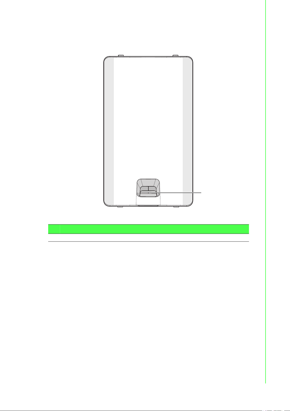
2.1.1 Front View
Figure 2.1 Front View
No. Item Description
Release tab Release tab for I/O port cover
1.
1
5 EKI-6333AC-2G Series User Manual
Page 15
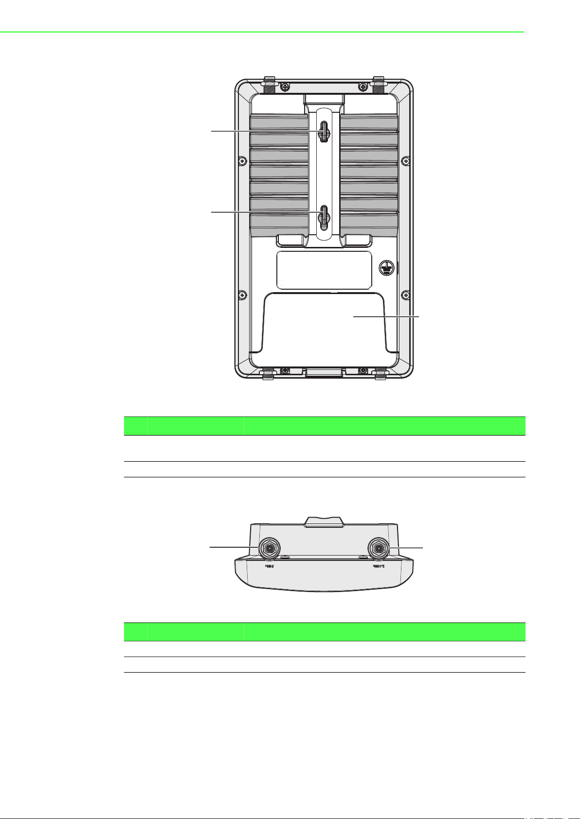
2.1.2 Rear View
1
1
2
No. Item Description
Quick mount keyhole
1.
slot
Cover I/O port cover
2.
2.1.3 Top View
No. Item Description
Antenna connector Reverse SMA connector for 5G WLAN antenna
1.
Antenna connector Reverse SMA connector for 2G WLAN antenna
2.
Figure 2.2 Rear View
Slots for mounting device to a wall
21
Figure 2.3 Top View
EKI-6333AC-2G Series User Manual 6
Page 16
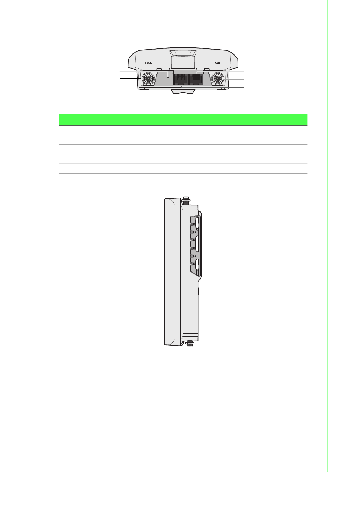
2.1.4 Bottom View
No. Item Description
ETH port LAN2 RJ45 port
1.
Antenna connector Reverse SMA connector for 2.4 GHz Wi-Fi antenna
2.
ETH port LAN1 RJ45 port, supports passive PoE
3.
Antenna connector Reverse SMA connector for 5 GHz Wi-Fi antenna
4.
Reset button Button allows for system soft reset or factory default reset
5.
2.1.5 Right View
5
4
Figure 2.4 Bottom View as Seen Without a Port Cover
1
2
3
Figure 2.5 Right View
7 EKI-6333AC-2G Series User Manual
Page 17
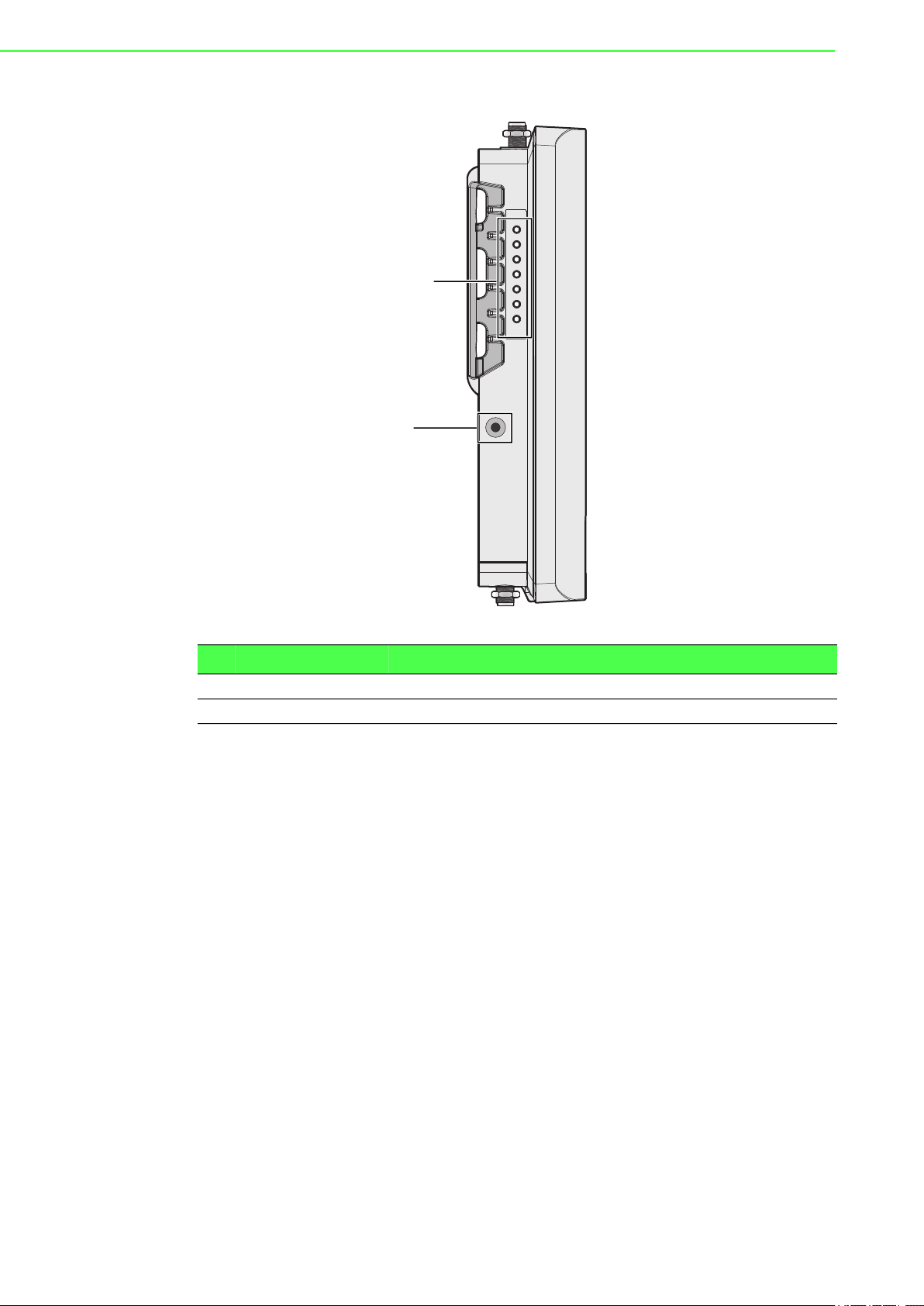
2.1.6 Left View
LAN 1
PWR
LAN 2
5GHz
2.4GHz
1
2
Figure 2.6 Left View
No. Item Description
System LED panel See “LED Indicators” on page 9 for further details.
1.
Ground terminal Screw terminal used to ground chassis
2.
EKI-6333AC-2G Series User Manual 8
Page 18

2.1.7 LED Indicators
LAN 1
PWR
LAN 2
5GHz
2.4GHz
No. LED Name LED Color Description
WLAN (5 GHz) Green on Wireless function is active
1.
Ethernet
2.
(LAN 2)
PWR Amber on Power is on
3.
Ethernet
4.
(LAN 1)
WLAN
5.
(2.4 GHz)
1
5
2
4
3
Figure 2.7 System LED Panel
Green blinking Wireless port is transmitting or receiving data
Green on 10/100/1000Mbps Ethernet connection
Green blinking Ethernet port is transmitting or receiving data
Amber blinking Boot state
Off Power is off or power error condition exists
Green on 10/100/1000Mbps Ethernet connection
Green blinking Ethernet port is transmitting or receiving data
Green on Wireless function is active
Green blinking Wireless port is transmitting or receiving data
9 EKI-6333AC-2G Series User Manual
Page 19

2.2 Connecting Hardware
2.2.1 Wall Mounting
This section provides instructions for installing the access point. It is recommended
that only personnel with an understanding of wireless access points and bridging
techniques and grounding methods install the device.
Warning! The installation of the access point must comply with local and national
electrical codes.
Note! When installing, make sure to allow for enough space to properly install
the cabling.
When mounting an access point, make sure the access point is oriented with the LED
indicators clearly visible.
In addition, the access point must be mounted in such a way as to ensure that all
antenna ports and the console port are accessible for future use.
1. On the installation site, place the device firmly against the wall. Make sure the
device is vertically and horizontally level.
2. Use the location of the keyhole slots on the back of the device to mark two
screw hole locations on the mounting surface.
3. Remove the device from the wall and drill holes over each marked location (2)
on the wall, keeping in mind that the holes must accommodate wall sinks in
addition to the screws.
4. Insert the wall sinks into the walls.
5. Insert a screw in a wall sink and rotate it to secure. Do not tighten at this point.
Repeat for the remaining location, see the following figure.
Figure 2.8 Mounting Screw Installation
6. Align the keyhole slots over the screws and insert the device in place.
EKI-6333AC-2G Series User Manual 10
Page 20

7. Slide the device down to sit it securely in the mounting screws.
1
1 2
Figure 2.9 Wall Mount Installation
2.2.2 Wireless Connection
Note! The location and position of the antenna is crucial for effective wireless
connectivity
1. Connect the top antennas by turning the antenna in the connectors in a
clockwise direction.
Figure 2.10 Installing the Top Antennas
11 EKI-6333AC-2G Series User Manual
Page 21

2. Repeat for the bottom locations.
Figure 2.11 Installing the Bottom Antennas
2.2.3 Network Connection
For RJ45 connectors, data-quality, twisted pair cabling (rated CAT5 or better) is
recommended. The connector bodies on the RJ45 Ethernet ports are metallic and
connected to the GND terminal. For best performance, use shielded cabling.
Shielded cabling may be used to provide further protection.
Straight-thru Cable Wiring Cross-over Cable Wiring
Pin 1 Pin 1 Pin 1 Pin 3
Pin 2 Pin 2 Pin 2 Pin 6
Pin 3 Pin 3 Pin 3 Pin 1
Pin 6 Pin 6 Pin 6 Pin 2
8
1
Figure 2.12 Ethernet Plug & Connector Pin Position
Maximum cable length: 100 meters (328 ft.) for 10/100BaseT.
EKI-6333AC-2G Series User Manual 12
Page 22

2.2.4 I/O Port Cover
Caution! Do not disconnect modules or cabling unless the power is first switched
off.
The device only supports the voltage outlined in the type plate. Do not
use any other power components except those specifically designated
for the device.
Caution! Disconnect the power cord before installation or cable wiring.
2.2.4.1 Removing a Port cover
1. Position the device so the bottom is facing upwards.
2. Align the Locate the top cover release as shown in the following figure.
3. Insert a tool through the opening and into the bottom of the release tab.
4. Gently lift the tab upwards and slide the tab towards the bottom.
Once the cover is released, the I/O ports on the back of the device are accessible.
2.2.4.2 Installing a Port Cover
1. Once the tab is unlocked, remove the cover from the device.
2. Position the device so the front is facing upwards.
To simplify this procedure, Ethernet cables are installed along with the cover.
3. Align the edges of the cover with the groves on the device bay. The ends of the
cover must be inserted underneath the groves.
Figure 2.13 Removing the I/O Cover
13 EKI-6333AC-2G Series User Manual
Page 23

4. Slide the cover into the bay and continue to slide it in place until an audible click
sounds indicating that the cover is locked in place.
Figure 2.14 Installing the I/O Cover
2.2.5 Power Connection
2.2.5.1 Overview
Warning! Power down and disconnect the power cord before servicing or wiring
the device.
Caution! Do not disconnect modules or cabling unless the power is first switched
off.
The device only supports the voltage outlined in the type plate. Do not
use any other power components except those specifically designated
for the device.
Caution! Disconnect the power cord before installation or cable wiring.
The EKI-6333AC-2G is powered by a passive 24Vdc PoE injector.
1. Locate the LAN1 port on the bottom of the access point.
2. Connect one end of a Ethernet cable to a PoE injector.
3. Connect the other end of the Ethernet cable to the LAN port supporting PoE on
the access point.
EKI-6333AC-2G Series User Manual 14
Page 24

The device powers on once the PoE injector supplies power to the access point.
Figure 2.15 Connecting Power to the PoE LAN Port
2.2.5.2 Grounding the Device
Caution! Do not disconnect modules or cabling unless the power is first switched
off.
The device only supports the voltage outlined in the type plate. Do not
use any other power components except those specifically designated
for the device.
Caution! Before connecting the device properly ground the device. Lack of a
proper grounding setup may result in a safety risk and could be
hazardous.
LAN port with
PoE support
Caution! Do not service equipment or cables during periods of lightning activity.
Caution! Do not service any components unless qualified and authorized to do
so.
Caution! Do not block air ventilation holes.
15 EKI-6333AC-2G Series User Manual
Page 25

Electromagnetic Interference (EMI) affects the transmission performance of a device.
LAN 1
PWR
LAN 2
5GHz
2.4GHz
By properly grounding the device to earth ground through a drain wire, you can setup
the best possible noise immunity and emissions.
Drain Wire with Lug
Connection to
Grounding Point
By connecting the ground terminal by drain wire to earth ground, the device and
chassis can be ground.
Note! Before applying power to the grounded device, it is advisable to use a
2.3 Reset Button
Reset configuration to factory default:
Press and hold Reset button for 5 seconds.
System reboot:
Figure 2.16 Grounding Connection
volt meter to ensure there is no voltage difference between the power
supply’s negative output terminal and the grounding point on the device.
EKI-6333AC-2G Series User Manual 16
Page 26

Press and hold Reset button for 2 seconds.
Reset Button
Figure 2.17 Reset Button Location
Note! Do NOT power off the WiFi AP when loading default settings.
17 EKI-6333AC-2G Series User Manual
Page 27

Chapter 3
3Web Interface
Page 28
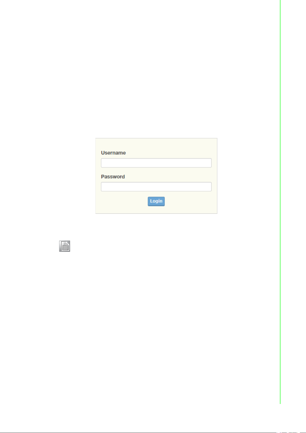
3.1 Log In
To access the login window, connect the device to the network, see “Network
Connection” on page 12. Once the device is installed and connected, power on the
device see the following procedures to log into your device.
When the device is first installed, the default IP is 192.168.1.1. You will need to make
sure your network environment supports the device setup before connecting it to the
network.
1. Launch your web browser on a computer.
2. In the browser’s address bar type in the device’s default IP address
(192.168.1.1). The login screen displays.
3. Enter the default user name and password (admin/admin) to log into the
management interface. You can change the default password after you have
successfully logged in.
4. Click Login to enter the management interface.
Figure 3.1 Login Screen
Note! Screen may differ depending on the Web browser.
19 EKI-6333AC-2G Series User Manual
Page 29

3.1.1 Password
The Management page allows you to configure the WiFi AP login details.
1. Log in to the user interface menu, see “Log In” on page 19.
2. Navigate to Home > Management > Password Manager. The Password
Manager page displays.
3. The profile to change is the current logged in profile. Enter the new password
under the Password field.
4. Re-type the same password in the Confirm Password field.
5. Click Apply to change the current account settings.
6. Once completed, the settings must be saved to the firmware to retain them after
a reboot. Navigate to Home > Management > Apply Configuration.
7. Click Apply and Reboot to save the settings.
Figure 3.2 Administration > HTTP
3.2 Overview
To access this page, Navigate to Home > Status and click Overview.
Figure 3.3 Status > Overview, System Info and LAN Interface
EKI-6333AC-2G Series User Manual 20
Page 30

Figure 3.4 Status > Overview, WAN Interface, DHCP Leases, & System Status
Item Description
System Info
Firmware Version Display the current firmware version of the device.
Local Hostname Display the current local hostname of the device.
System Time Displays the current date of the device.
System Up Time Displays the time since the last device reboot.
Model Name Displays the model name of the device.
LAN Interface
LAN Status Displays the current LAN and MAC settings, TX packets/bytes,
and RX packets/bytes.
Wireless - 2.4GHz Displays the current settings for the 2.4GHz interface, listing the
access point mode, SSID name, BSSID, encryption type,
broadcast channel, TX power, and assigned region (country).
Wireless - 5GHz Displays the current settings for the 5GHz interface, listing the
access point mode, SSID name, BSSID, encryption type,
broadcast channel, TX power, and assigned region (country).
WAN Interface
Local IP Address Displays the type of WAN physical interface setup: Disabled
(default), static, DHCP, PPPoE.
DHCP Leases
Displays the defined list of DHCP leases that the DHCP server has
assigned.
Defines hostname, IPv4-Address, MAC-Address, and Lease Time
Remaining.
System Status
Memory Utilization Displays the total memory utilization in terms of percentage.
CPU Utilization Displays the total CPU utilization in terms of percentage.
3.3 Address Resolution Protocol
The Address Resolution Protocol (ARP) allows mapping of dynamic Internet Protocol
addresses (IP address) to a permanent physical machine address in a local area
network (LAN) through the use of the MAC address.
21 EKI-6333AC-2G Series User Manual
Page 31

To access this page, Navigate to Home > Status and click ARP.
The following table describes the items in the previous figure.
Item Description
ARP Table
IP Address Displays the mapped IP address.
MAC Displays the MAC address of the defined IP list entry.
Interface Displays the defined interface of the mapped address.
3.4 Interface Settings
3.4.1 LAN
To access this page, click Interface > LAN.
Figure 3.5 Status > ARP
Figure 3.6 Interface > LAN
EKI-6333AC-2G Series User Manual 22
Page 32

The following table describes the items in the previous figure.
Item Description
Local Hostname Enter the device name: up to 31 alphanumeric characters.
Domain Name Enter the text string to define the name of a domain.
Network mode Click the drop-down menu to select the IP Address Setting mode:
Static or DHCP.
IP Address Enter a value to specify the IP address of the interface. The default
is 192.168.1.1.
Subnet Mask Enter a value to specify the IP subnet mask for the interface. The
default is 255.255.255.0.
Spanning Tree Click the radio button to enable or disable (default) the spanning
tree service.
DHCP Server
DHCP Server Click the radio button to enabled or disabled the DHCP server
function.
Start IP Address Enter starting a IP address for the IP assignment.
Pool Counter Enter a variable to define the number of IP addresses for a given
network.
Lease Time Enter in the value designating the lease time for the DHCP server.
Static DNS 1 Enter in the value designating the primary static DNS.
Static DNS 2 Enter in the value designating the secondary static DNS.
Submit Click Submit to save the values and update the screen.
Note! All new configurations will take effect after rebooting. To reboot the
3.4.2 WAN
To access this page, click Interface > WAN.
The Interface screen allows user to setup the WAN interface and its network function
mode.
When WAN Type (Network Mode) is Disable (default), the Interface Setup
configuration settings appear.
The following table describes the items in the previous figure.
device, click Management > Apply Configuration > Apply and
Reboot.
Figure 3.7 Interface > WAN > Network Mode
Item Description
Network Mode Click the drop-down menu to select the mode type: Disable
(default), Static, DHCP, PPPoE.
WAN Interface Click the radio button to select the specific interface to configure.
Submit Click Submit to save the values and update the screen.
23 EKI-6333AC-2G Series User Manual
Page 33

When WAN Type (Network Mode) is Static, the Static WAN Type configuration
settings appear.
Figure 3.8 Interface > WAN > Network Mode > Static
The following table describes the items in the previous figure.
Item Description
Network Mode Click the drop-down menu to select the mode type: Disable
(default), Static, DHCP, PPPoE.
WAN Interface Click the radio button to select the specific interface to configure.
IP Address Enter the WAN IP address given by your service provider.
Subnet Mask Enter the WAN subnet mask given by your service provider.
Default Gateway Enter the WAN gateway IP address given by your service provider.
Static DNS 1 Enter the primary WAN DNS IP address given by your service
provider.
Static DNS 2 Enter the secondary WAN DNS IP address given by your service
provider.
Submit Click Submit to save the values and update the screen.
When WAN Type (Network Mode) is DHCP, the DHCP WAN Type configuration
settings appear.
Figure 3.9 Interface > WAN > Network Mode
The following table describes the items in the previous figure.
Item Description
Network Mode Click the drop-down menu to select the mode type: Disable
(default), Static, DHCP, PPPoE.
WAN Interface Click the radio button to select the specific interface to configure.
Submit Click Submit to save the values and update the screen.
EKI-6333AC-2G Series User Manual 24
Page 34

When WAN Type (Network Mode) is PPPoE, the PPPoE WAN Type configuration
settings appear.
Figure 3.10 Interface > WAN > Network Mode > PPPoE
The following table describes the items in the previous figure.
Item Description
Network Mode Click the drop-down menu to select the mode type: Disable
(default), Static, DHCP, PPPoE.
WAN Interface Click the radio button to select the specific interface to configure.
Username Enter the PPPoE user name (account) provided by your service
provider.
Password Enter the PPPoE password provided by your service provider.
Service Name Enter the service name if your ISP requires it.
MTU Check Enable check box to enable the MTU (Maximum
Transmission Unit) limit, and specify the MTU for the 3G/4G
connection.
MTU refers to Maximum Transmission Unit. It specifies the largest
packet size permitted for Internet transmission.
Value Range: 1200 ~ 1500.
Submit Click Submit to save the values and update the screen.
3.4.3 Wireless 2.4GHz
To access this page, click Interface > Wireless - 2.4GHz.
3.4.3.1 Basic
Basic wireless settings offer three types of configurable modes, Access Point, Client,
and Bridged Repeater.
The following descriptions provide further details for each specific mode.
25 EKI-6333AC-2G Series User Manual
Page 35

Access Point Mode
To access this page, click Wireless - 2.4GHz > Basic and select Access Point in
Operation Mode.
Figure 3.11 Wireless - 2.4GHz > Basic > Access Point
The following table describes the items in the previous figure.
Item Description
Wireless Network
Operation Mode Click the drop-down menu to select an operation mode: Access
Point, Client, Bridged Repeater.
WDS Click the radio button to enable or disable the Wireless Distribution
System (WDS) to allow you to link the Access Points wirelessly.
SSID Enter the name to distinguish it from other networks in your
neighborhood.
SSID Broadcast Click the drop-down menu to enable or disable the SSID broadcast
function. The function is only enabled when Operation Mode is set
to Access Point.
AP Isolation Click the drop-down menu to enable or disable the AP Isolation
function.The function is only enabled when Operation Mode is set
to Access Point.
BSSID Display the MAC address of the device.
Maximum Clients Enter the value (1 to 30) designating the maximum number of
clients per wireless device.
Management Frame
Protection
Operation frequency
Click the radio button to enable, disable, or set the function to
optional. The wireless feature increases the security of the
management frames, standard: IEEE 802.11W-2009.
EKI-6333AC-2G Series User Manual 26
Page 36

Item Description
Country Code Click the drop-down menu to select the country code to specify
different selectable channels. Available options: US (United
States), Germany, France, China and Japan. Some specific
channels and/or operational frequency bands are country
dependent.
Channel Selection Click the drop-down menu to select Auto (default) or Manual. The
Auto selection allows the device to select a band. The Manual
selection provides access to a selection of the option band (2.4G /
5G). The function is only enabled when Operation Mode is set to
Client.
Band Click the drop-down menu to select the band channel.
Band / Channel
bandwidth
Channel / Frequency Click the drop-down menu to select a wireless channel/frequency:
Click the drop-down menu to select the band and channel
bandwidth: 11b/g - Non-HT (Legacy), 11n - HT20, 11n - HT40, or
11ac - VHT 80.
– AutoSelect
– Channel 1: 2.412 GHz
– Channel 2: 2.417 GHz
– Channel 3: 2.422 GHz
– Channel 4: 2.427 GHz
– Channel 5: 2.432 GHz
– Channel 6: 2.437 GHz
– Channel 7: 2.442 GHz
– Channel 8: 2.447 GHz
– Channel 9: 2.452 GHz
– Channel 10: 2.457 GHz
– Channel 11: 2.462 GHz
– Channel 12: 2.467 GHz
– Channel 13: 2.472 GHz
– Channel 14: 2.484 GHz (802.11b)
Submit Click Submit to save the values and update the screen.
Client Mode
To access this page, click Wireless - 2.4GHz > Basic and select Client in Operation
Mode.
Figure 3.12 Wireless - 2.4GHz > Basic > Client
27 EKI-6333AC-2G Series User Manual
Page 37

The following table describes the items in the previous figure.
Item Description
Wireless Network
Operation Mode Click the drop-down menu to select an operation mode: Access
Point, Client, Bridged Repeater.
WDS Click the radio button to enable or disable the Wireless Distribution
System (WDS) to allow you to link the Access Points wirelessly.
SSID Enter the name to distinguish it from other networks in your
neighborhood.
BSSID Displays the basic service set identifiers (BSSID) for the device.
Scan AP Click to rescan the selected SSID.
Management Frame
Protection
Operation frequency
Country Code Click the drop-down menu to select the country code to specify
Channel Selection Click the drop-down menu to select Auto (default) or Manual. The
Channel bandwidth Click the drop-down menu to select the band and channel
Submit Click Submit to save the values and update the list.
Click the radio button to enable, disable, or set the function to
optional. The wireless feature increases the security of the
management frames, standard: IEEE 802.11W-2009.
different selectable channels. Available options: US (United
States), Germany, France, China and Japan. Some specific
channels and/or operational frequency bands are country
dependent.
Auto selection allows the device to select a band. The Manual
selection provides access to a selection of the option band (2.4G /
5G). The function is only enabled when Operation Mode is set to
Client.
bandwidth: 11b/g - Non-HT (Legacy), 11n - HT20, 11n - HT40, or
11ac - VHT 80.
Bridged Repeater Mode
To access this page, click Wireless - 2.4GHz > Basic and select Bridged Repeater
in Operation Mode.
Figure 3.13 Wireless - 2.4GHz > Basic > Bridged Repeater
EKI-6333AC-2G Series User Manual 28
Page 38

The following table describes the items in the previous figure.
Item Description
Wireless Network
Operation Mode Click the drop-down menu to select an operation mode: Access
Point, Client, Bridged Repeater.
WDS Click the radio button to enable or disable the Wireless Distribution
System (WDS) to allow you to link the Access Points wirelessly.
Main SSID Enter the source SSID network to be repeated.
BSSID Displays the basic service set identifiers (BSSID) for the device.
Scan AP Click to rescan the selected SSID.
Extender SSID Enter the AP device to be used as the extender.
Management Frame
Protection
Operation frequency
Country Code Click the drop-down menu to select the country code to specify
Band Click the drop-down menu to select the band channel.
Band / Channel
bandwidth
Channel / Frequency Click the drop-down menu to select a wireless channel/frequency:
Click the radio button to enable, disable, or set the function to
optional. The wireless feature increases the security of the
management frames, standard: IEEE 802.11W-2009.
different selectable channels. Available options: US (United
States), Germany, France, China and Japan. Some specific
channels and/or operational frequency bands are country
dependent.
Click the drop-down menu to select the band and channel
bandwidth: 11b/g - Non-HT (Legacy), 11n - HT20, 11n - HT40, or
11ac - VHT 80.
– AutoSelect
– Channel 1: 2.412 GHz
– Channel 2: 2.417 GHz
– Channel 3: 2.422 GHz
– Channel 4: 2.427 GHz
– Channel 5: 2.432 GHz
– Channel 6: 2.437 GHz
– Channel 7: 2.442 GHz
– Channel 8: 2.447 GHz
– Channel 9: 2.452 GHz
– Channel 10: 2.457 GHz
– Channel 11: 2.462 GHz
– Channel 12: 2.467 GHz
– Channel 13: 2.472 GHz
– Channel 14: 2.484 GHz (802.11b)
Submit Click Submit to save the values and update the screen.
3.4.3.2 Advanced
Access Point Settings
The Access Point Settings as displayed in the following figure are available when the
operation mode (Wireless Network) is set to access point.
29 EKI-6333AC-2G Series User Manual
Page 39

To access this page, click Wireless - 2.4GHz > Advanced.
Figure 3.14 Wireless - 2.4GHz > Advanced
The following table describes the items in the previous figure.
Item Description
Access Point Settings
Beacon Interval Enter a value (20-999) to specify the frequency interval to
broadcast packets.
Data Beacon Rate
(DTIM)
20/40 Coexistence Select enable to select 20/40 MHz coexistence. Once enabled, the
HT LDPC Enable to advertise Low-density Parity Check (LDPC) support. By
Station Inactivity Time Enter the value in seconds (30 to 600, default 300) to define the
Advanced Wireless Setting
RTS Threshold Enter a value (1-2347) to specify the request time to send
Transmission Power Click the drop-down menu to set the transmission power (9 - 21
WMM Enable WiFi Multimedia (WMM) to enhance the quality of service
DTIM, which stands for Delivery Traffic Indication Message, is
contained in the data packets. It is for enhancing the wireless
transmission efficiency. The default is set to 2. Enter a value
between 1 and 255.
device allows clients operating only on a single channel (20 MHz)
to connect to the wireless network (default: disabled).
enabling HT LDPC, the function improves data transmission over
channels with a high degree of background noise (default:
enabled).
period of traffic inactivity for a client before the AP removes it.
threshold.
dBm) of the WiFi. By default the AP transmits at 21 dBm.
(QoS) on a network by prioritizing packet data based.
EKI-6333AC-2G Series User Manual 30
Page 40

Item Description
Short Guard Interval Click the drop-down menu to enable/disable the short guard
interval. In 802.11 operation, the guard interval is 800ns. The short
guard interval time is 400ns to allow for an increased throughput.
Submit Click Submit to save the values and update the screen.
Client Settings
The Client Settings as displayed in the following figure are available when the
operation mode (Wireless Network) is set to client.
To access this page, click Wireless - 2.4GHz > Advanced.
Figure 3.15 Wireless - 2.4GHz > Advanced
The following table describes the items in the previous figure.
Item Description
Client Settings
Roam Click to enable or disable the roaming function allowing it to
automatically switch to another AP with a better signal strength.
Watchdog Click to disable the function, disassociate or ping a specific IP
address.
The function stops unsecured wireless LAN usage across the
network.
Disassociation: Transmits disassociation and
deauthentication frames to prevent client association.
Detected rogue WLANs.
Ping: The feature pings a specified IP address. If there is no
response to the pings, the AP performs one of the following
functions: Restart WiFi, Reboot, or Force Re-association.
Watchdog Action Available when Watchdog is set to disassociate.
Click the drop-down menu to associate a response to the
Watchdog event, options: Restart WiFi, Reboot, Force
Reassociation.
Disassociate Timer Available when Watchdog is set to disassociate.
Ping Target Available when Watchdog is set to ping.
Enter the IP address to target when watchdog ping is activated.
Ping Waittime Available when Watchdog is set to ping.
Enter the value in seconds to designate the interval between
pings.
31 EKI-6333AC-2G Series User Manual
Page 41

Item Description
Ping Loss Counter Available when Watchdog is set to ping.
MAC Clone Click to enable or disable the function, which allows the cloning of
Clone Method Available when MAC Clone is enabled.
Advanced Wireless Setting
Transmission Power Click the drop-down menu to set the transmission power (9 - 21
Short Guard Interval Click the drop-down menu to enable/disable the short guard
Submit Click Submit to save the values and update the screen.
3.4.3.3 Security
To access this page, click Wireless - 2.4GHz > Security.
Enter a value to activate the Watchdog function when the
configured number of ping failure time is reached.
a wireless MAC address to connect an AP.
Click to select the clone method, Auto or Manual. By selecting
Manual, you can enter the MAC address in the Clone MAC
Address field.
dBm) of the WiFi. By default the AP transmits at 21 dBm.
interval. In 802.11 operation, the guard interval is 800ns. The short
guard interval time is 400ns to allow for an increased throughput.
Figure 3.16 Wireless - 2.4GHz > Security
In Bridged Repeater mode, the security / encryption settings are displayed as follows.
See the following figure.
Figure 3.17 Wireless - 2.4GHz > Security
Item Description
Security Policy
EKI-6333AC-2G Series User Manual 32
Page 42

Item Description
Security Mode Click the drop-down menu to select the encryption when
communication. Available options: None, WEP, WPA-Personal and
WPA/WPA2-Enterprise. If data encryption is enabled, the key is
required and only sharing the same key with other wireless
devices can the communication be established.
Submit Click Submit to save the values and update the screen.
Security Policy (Main)
Security Mode Click the drop-down menu to select the encryption when
communication. Available options: None, WPA-Personal and WPA/
WPA2-Enterprise. If data encryption is enabled, the key is required
and only sharing the same key with other wireless devices can the
communication be established.
Submit Click Submit to save the values and update the screen.
Submit and client use
the same security.
Security Policy (Extender)
Security Mode Click the drop-down menu to select the encryption when
Submit Click Submit to save the values and update the screen.
Click Submit to push the settings to the client.
communication. Available options: None, WPA-Personal and WPA/
WPA2-Enterprise. If data encryption is enabled, the key is required
and only sharing the same key with other wireless devices can the
communication be established.
3.4.3.4 Multiple SSID
The Multiple SSID feature is only available when the wireless mode of the device is
set to AP, see “Management” on page 42.
To access this page, click Wireless - 2.4GHz > Multiple SSID.
Figure 3.18 Wireless - 2.4GHz > Multiple SSID
33 EKI-6333AC-2G Series User Manual
Page 43

The following table describes the items in the previous figure.
Item Description
Add Click Add after completing the SSID information to create the
wireless network and list it in the menu.
Add SSID
State Click the radio button to designate the state (enabled/disabled) of
the defined SSID.
SSID Enter the text string identifying the name of the SSID.
SSID Broadcast Click the drop-down menu to enable (visible) or disable (not
broadcasted) the broadcasting of the SSID name
Management Frame
Protection
Security Policy
Security Mode Click the drop-down menu to select the encryption when
Submit Click Submit to save the values and update the screen.
Click the radio button to enable, disable, or set the function to
optional. The wireless feature increases the security of the
management frames, standard: IEEE 802.11W-2009.
communication. Available options: None, WPA-Personal and WPA/
WPA2-Enterprise. If data encryption is enabled, the key is required
and only sharing the same key with other wireless devices can the
communication be established.
3.4.3.5 QoS
The QoS feature is only available when the wireless mode of the device is set to AP
or Bridged Repeater, see “Management” on page 42.
The QoS function is only available in Access Point mode.
To access this page, click Wireless - 2.4GHz > QoS.
The following table describes the items in the previous figure.
Item Description
Interface Name Click the drop-down menu to select an interface from the list of
QoS Click the radio button to enable or disable the QoS policy on the
Download Speed (kbit/s) Enter the value (kbit/s) to define the download speed of the policy:
Upload Speed (kbit/s) Enter the value (kbit/s) to define the upload speed of the policy:
Submit Click Submit to save the values and update the screen.
Figure 3.19 Wireless - 2.4GHz > QoS
already created wireless networks.
selected interface.
1024 to 102400, default: 85000)
1024 to 102400, default: 10000)
EKI-6333AC-2G Series User Manual 34
Page 44

3.4.3.6 Statistics
To access this page, click Wireless - 2.4GHz > Statistics.
Figure 3.20 Wireless - 2.4GHz > Statistics
The following table describes the items in the previous figure.
Item Description
Overview
Mode Display the current operation mode of the device.
SSID Display the SSID.
Channel / Frequency Display the current channel / frequency of the device.
BSSID Display the MAC address of the device.
Station List
Station BSSID Displays the basic service set identifier (BSSID), access point
unique MAC address.
Signal level Displays the power level measure in decibel-milliwatts of the listed
BSSID.
Connected time Displays the total uptime period.
Tx/Rx rate Displays the transmit (Tx) to receive (Rx) rate of the connected
client.
Tx packets/bytes Displays the total Tx packets and corresponding bytes.
Rx packets/bytes Displays the total Rx packets and corresponding bytes.
Wlan status
TX packets Display the current Tx packets.
TX bytes Display the current Tx bytes.
RX packets Display the current Rx packets.
RX bytes Display the current Rx bytes.
3.4.3.7 Access Control
The Access Control feature is only available when the wireless mode of the device is
set to AP, see “Management” on page 42.
35 EKI-6333AC-2G Series User Manual
Page 45

Access Control allows for an administrator to allow or deny access by defining
specific devices through their MAC address.
To access this page, click Wireless - 2.4GHz > Access Control.
Figure 3.21 Wireless - 2.4GHz > Access Control
The following table describes the items in the previous figure.
Item Description
SSID Click the drop-down menu to select the SSID from the list of
already created wireless networks.
Access Control Method Click the drop-down menu to set the access control method:
Disable, Deny or Allow.
In the Deny or Allow menu, enter the MAC address of the target
device - support for up to 32 target devices.
Submit Click Submit to save the values and update the screen.
3.4.3.8 Site Survey
The Site Survey feature is only available when the wireless mode of the device is set
to Client or Bridged Repeater mode, see “Management” on page 42.
To access this page, click Wireless - 2.4GHz > Site Survey.
Item Description
Refresh Click to update the displayed AP list table.
AP list
SSID Displays the name of the listed AP.
BSSID Displays the basic service set identifiers (BSSID) used to describe
Frequency Displays the radio frequency of the listed SSID.
Signal level Displays the signal level of the listed SSID.
Encryption Displays the encryption type assigned to the listed SSID.
Figure 3.22 Wireless - 2.4GHz > Site Survey
the section of the SSID.
3.4.3.9 VLAN
The VLAN function allows for the processing of data to and from clients in the same
manner as data is processed to and from wired connections.
EKI-6333AC-2G Series User Manual 36
Page 46

To access this page, click Wireless - 2.4GHz > Site Survey.
Figure 3.23 Wireless - 2.4GHz > Site Survey
Item Description
VLAN ID Enter a variable (1 to 127) to identify the VLAN entry.
Port Click a specific interface (LAN 1 / LAN 2) to designate to the VLAN
entry.
Wireless SSID Click the drop-down menu to select an SSID entry to configure to
the VLAN entry.
Delete Click Delete to remove the VLAN entry from the list.
Add Click Add after completing the SSID information to create the
wireless network and list it in the menu.
Submit Click Submit to save the values and update the screen.
37 EKI-6333AC-2G Series User Manual
Page 47

3.4.3.10 Log
To access this page, click Wireless - 2.4GHz > Log.
The following table describes the items in the previous figure.
Item Description
Download Click Download to download the log file.
Auto Scroll Click the option to allow for auto scrolling when the log entries has
3.4.4 Wireless 5GHz
To access this page, click Interface > Wireless - 5GHz.
For further details regarding the user interface, refer to the Wireless 2.4GHz section.
See “Wireless 2.4GHz” on page 25.
Figure 3.24 Wireless - 2.4GHz > Log
extended below the page line.
EKI-6333AC-2G Series User Manual 38
Page 48

3.5 Network Settings
3.5.1 Static Route
To access this page, click Networking > Static Route.
Figure 3.25 Networking > Static Route
The following table describes the items in the previous figure.
Item Description
Target IP Address Enter an IP address (static route) for this static route.
Netmask Enter a netmask setting (static route) for this static route.
Gateway Enter a gateway setting (static route) for this static route.
Interface Enter an interface for this static route, options: LAN, WAN,
Wireless 2.4GHz, or Wireless 5GHz.
Metric Enter the administrative distance (default: 1) used by the ap to
choose the best path for two or more routes to the same
destination.
MTU Enter the maximum transmission value for the data packets if
applicable.
Delete Click Delete to remove the route from the available list.
Add Click Add to include the route in the static routing policy.
Submit Click Submit to save the values and update the screen.
3.5.2 Forwarding
3.5.2.1 Port Forwarding
To access this page, click Networking > Forwarding > Port Forwarding.
Figure 3.26 Networking > Forwarding > Port Forwarding
The following table describes the items in the previous figure.
Item Description
Enabled Click Download to download the log file.
Name Enter a text string to identify the port forwarding entry.
Start Port Enter the value of the starting port for this entry.
39 EKI-6333AC-2G Series User Manual
Page 49

Item Description
End Port Enter the value of the ending port for this entry.
Local IP Enter the IP address defining the static address of the local IP.
Local Port Enter the value defining the local port.
Protocol Click the drop-down menu to select the protocol setting, options:
Delete Click Delete to remove the selected entry from the port forwarding
Add Click Add to include the entry in the port forwarding policy.
Submit Click Submit to save the values and update the screen.
3.5.2.2 DMZ
To access this page, click Networking > Forwarding > DMZ.
TCP, UDP, Both.
policy.
The following table describes the items in the previous figure.
Item Description
DMZ Click the radio button to enable or disable the DMZ function.
IP Enter the IP address to designate a static IP address as the DMZ
Submit Click Submit to save the values and update the screen.
3.5.3 Security
3.5.3.1 Filter To access this page, click Networking > Security > Filter.
Figure 3.27 Networking > Forwarding > DMZ
target.
Figure 3.28 Networking > Security > Filter
Item Description
Filter Click the radio button to enable or disable the Filter policy.
Enabled Select to enable the defined filter entry.
Direction Click the drop-down menu to select the direction of the data packet
taffic for the entry: LAN to WAN, WAN to LAN.
Source IP Enter the IP address of the sender address.
Destination IP Enter the IP address of the destination address.
EKI-6333AC-2G Series User Manual 40
Page 50

Item Description
Protocol Click the drop-down menu to select the protocol type for the entry:
Source port Enter the port number of the sender IP address.
Destination port Enter the port number of the destination IP address.
Delete Click Delete to remove the entry from the Filter policy.
Add Click Add to include the entry in the Filter policy.
Submit Click Submit to save the values and update the policy.
3.5.3.2 VPN Passthrough To access this page, click Networking > Security > VPN Passthrough.
Figure 3.29 Networking > Security > VPN Passthrough
TCP, UDP, ICMP.
Item Description
PPTP Passthrough Click the radio button to enable or disable PPTP packets to pass
through.
L2TP Passthrough Click the radio button to enable or disable L2TP packets to pass
through.
IPSec Passthrough Click the radio button to enable or disable IPSEC packets to pass
through.
Submit Click Submit to save the values and update the policy.
41 EKI-6333AC-2G Series User Manual
Page 51

3.6 Management
3.6.1 Password Manager
To access this page, click Management > Password Manager.
Figure 3.30 Management > Password Manager
The following table describes the items in the previous figure.
Item Description
Password Enter the text string to define a password for the listed username
entry.
Confirm Password Re-type the text string as identified in the password field to confirm
the entry.
Submit Click Submit to save the values and update the screen.
3.6.2 Syslog
Users can enable the syslogd function to record historical events or messages locally
or on a remote syslog server.
EKI-6333AC-2G Series User Manual 42
Page 52

To access this page, click Management > Syslog.
Figure 3.31 Management > Syslog
The following table describes the items in the previous figure.
Item Description
Remote Log Click the radio button to enable or disable the remote log function.
Enabling the function allows for the saving of log entries on a
remote, not local, system.
IP Address Enter the static address of the remote system used for storing
logging information.
Port Enter the port number of the define static address used for storing
logging information.
Submit Click Submit to save the values and update the screen.
Download Click Download to download the log file.
Auto Scroll Click the option to allow for auto scrolling when the log entries has
extended below the page line.
43 EKI-6333AC-2G Series User Manual
Page 53

3.6.3 NTP / Time
To access this page, click Management > NTP / Time.
The following table describes the items in the previous figure.
Item Description
System Time Displays the current system time settings.
Manual Time To enable manual configuration, NTP Service option must first be
NTP Service Click the drop-down menu to enable or disable the NTP server. By
Time Zone Click the drop-down menu to select a system time zone.
NTP Server Enter the address of the SNTP server.
Submit Click Submit to save the values and update the screen.
Figure 3.32 Management > NTP / Time
disabled. Manually enter the Year, Month, Day, Hour, Minute, and
Second settings to define the system time.
disabling this function, the Manual Time setting can be configured.
EKI-6333AC-2G Series User Manual 44
Page 54

3.6.4 SNMP
To access this page, click Management > SNMP.
Figure 3.33 Management > SNMP
The following table describes the items in the previous figure.
Item Description
SNMP System settings
SNMP Click the radio button to enable or disable the Simple Network
Management Protocol (SNMP) function used to monitor network
devices.
Contact Enter the contact route in an Email format for use during an SNMP
event.
Name Enter the text string describing the contact entry.
Location Enter the text string describing the region/location of the contact
entry.
Description Enter a descriptive remark to better identify the contact entry.
SNMP Daemon Settings
Version Click the drop-down menu to select the version of the daemon.
Server Port Enter the port to access on the specified server.
Read Community Enter the setting to define the level of read access for the defined
user, options: private, public (default).
Write Community Enter the setting to define the level of write access for the defined
user, options: private (default), public.
SNMP Trap Settings
Trap Server IP Enter the static route to define the trap server used for the defined
user.
45 EKI-6333AC-2G Series User Manual
Page 55

Item Description
Trap Community Enter the setting to define the level of access for the define user,
Submit Click Submit to save the values and update the screen.
3.6.5 Remote Services
To access this page, click Management > Remote Services.
options: private, public.
Figure 3.34 Management > Remote Services
The following table describes the items in the previous figure.
Item Description
HTTP common settings
Redirect HTTP requests
to HTTPS
HTTPS port Enter the port to forward HTTPS traffic, default: 443.
HTTP port Enter the port to forward HTTP traffic, default: 80.
SSH
SSH Click the radio button to enable or disable access to SSH function.
Telnet
Telnet Click the radio button to enable or disable access to the Telnet
FTP Server
FTP Server Click the radio button to enable or disable access to the FTP
Submit Click Submit to save the values and update the screen.
Click the drop-down menu to enable or disable the function. By
default the function is disabled. When enabled, a NAT setting and
Open Ports can be setup to direct connection requests to an
internal server.
function.
Server function.
EKI-6333AC-2G Series User Manual 46
Page 56

3.6.6 Configuration Manager
To access this page, click Management > Configuration Manager.
Figure 3.35 Management > Configuration Manager
The following table describes the items in the previous figure.
Item Description
Backup
Backup Click Backup to export the device settings.
Restore
Upload Archive Click Upload Archive to select a previously saved configuration
file.
3.6.7 Firmware Upgrade
To access this page, click Management > Firmware Upgrade.
Figure 3.36 Management > Firmware Upgrade
The following table describes the items in the previous figure.
Item Description
Choose File Click Choose File to select the configuration file.
Upload Click Upload to upload to the current version.
3.6.8 Reset System
To access this page, click Management > Apply Configuration.
Figure 3.37 Management > Apply Configuration
47 EKI-6333AC-2G Series User Manual
Page 57

The following table describes the items in the previous figure.
Item Description
Reset Click Reset the device, any changes to settings will be lost unless
the Apply Configuration function is executed prior to resetting.
3.6.9 Apply Configuration
To access this page, click Management > Apply Configuration.
Figure 3.38 Management > Apply Configuration
The following table describes the items in the previous figure.
Item Description
Apply and Reboot Click Apply and Reboot to save the new configuration settings
and reboot the device to permanently save the new settings.
3.6.10 Reboot Device
To access this page, click Management > Reboot Device.
Figure 3.39 Management > Reboot Device
The following table describes the items in the previous figure.
Item Description
Reboot Click Reboot to reboot the device. Any configuration changes you
have made since the last time you issued a save will be lost.
EKI-6333AC-2G Series User Manual 48
Page 58

3.7 Tools
3.7.1 Diagnostics
To access this page, click Tools > Diagnostics.
Figure 3.40 Tools > Diagnostics
The following table describes the items in the previous figure.
Item Description
IP Address or Hostname Enter the IP address or host name of the station to ping. The initial
value is blank. The IP Address or host name you enter is not
retained across a power cycle. Host names are composed of
series of labels concatenated with periods. Each label must be
between 1 and 63 characters long, maximum of 64 characters.
Ping Click Ping to display ping result for the IP address.
IP Address or Hostname Enter the IP address or host name of the station to ping. The initial
value is blank. The IP Address or host name you enter is not
retained across a power cycle. Host names are composed of
series of labels concatenated with periods. Each label must be
between 1 and 63 characters long, maximum of 64 characters.
Traceroute Click Traceroute to track the pathway taken by a packet on the
designated network from source to destination.
Results Displays the results of the Ping or Traceroute function after
initializing.
49 EKI-6333AC-2G Series User Manual
Page 59

www.advantech.com
Please verify specifications before quoting. This guide is intended for reference
purposes only.
All product specifications are subject to change without notice.
No part of this publication may be reproduced in any form or by any means,
electronic, photocopying, recording or otherwise, without prior written
permission of the publisher.
All brand and product names are trademarks or registered trademarks of their
respective companies.
© Advantech Co., Ltd. 2020
 Loading...